EP3486206A1 - Automatic accessory for lifting loads - Google Patents
Automatic accessory for lifting loads Download PDFInfo
- Publication number
- EP3486206A1 EP3486206A1 EP16902278.7A EP16902278A EP3486206A1 EP 3486206 A1 EP3486206 A1 EP 3486206A1 EP 16902278 A EP16902278 A EP 16902278A EP 3486206 A1 EP3486206 A1 EP 3486206A1
- Authority
- EP
- European Patent Office
- Prior art keywords
- shaft
- load
- fixture
- lifting
- automatic load
- Prior art date
- Legal status (The legal status is an assumption and is not a legal conclusion. Google has not performed a legal analysis and makes no representation as to the accuracy of the status listed.)
- Granted
Links
Images


Classifications
-
- B—PERFORMING OPERATIONS; TRANSPORTING
- B66—HOISTING; LIFTING; HAULING
- B66C—CRANES; LOAD-ENGAGING ELEMENTS OR DEVICES FOR CRANES, CAPSTANS, WINCHES, OR TACKLES
- B66C1/00—Load-engaging elements or devices attached to lifting or lowering gear of cranes or adapted for connection therewith for transmitting lifting forces to articles or groups of articles
- B66C1/10—Load-engaging elements or devices attached to lifting or lowering gear of cranes or adapted for connection therewith for transmitting lifting forces to articles or groups of articles by mechanical means
- B66C1/62—Load-engaging elements or devices attached to lifting or lowering gear of cranes or adapted for connection therewith for transmitting lifting forces to articles or groups of articles by mechanical means comprising article-engaging members of a shape complementary to that of the articles to be handled
- B66C1/66—Load-engaging elements or devices attached to lifting or lowering gear of cranes or adapted for connection therewith for transmitting lifting forces to articles or groups of articles by mechanical means comprising article-engaging members of a shape complementary to that of the articles to be handled for engaging holes, recesses, or abutments on articles specially provided for facilitating handling thereof
- B66C1/663—Load-engaging elements or devices attached to lifting or lowering gear of cranes or adapted for connection therewith for transmitting lifting forces to articles or groups of articles by mechanical means comprising article-engaging members of a shape complementary to that of the articles to be handled for engaging holes, recesses, or abutments on articles specially provided for facilitating handling thereof for containers
Definitions
- the present invention relates to an automatic load-lifting fixture, which has been designed to move loads using a lifting machine or device that is able to support and lift said load.
- the object of the invention is to provide a fixture by means of which the attachment to the corresponding load to be lifted is carried out automatically, including also means for manual actuation or operation.
- the proposed device has a range of characteristics that provide numerous benefits and new features, as will be explained below.
- the fixture that is the object of this invention consists of a prism-shaped and elongated general frame, on one end of which a shaft is mounted horizontally that can be rotated either manually or automatically by remote control using an electro-pneumatic or electro-hydraulic actuating cylinder, such that one end of said shaft attaches to an eyebolt and a shackle in order to latch onto the lifting machine, while the other end features a type of triangular cross-piece to engage with the load to be lifted.
- the electro-pneumatic and electro-hydraulic means are housed inside the frame casing, as is a rechargeable battery to power all the electrically operated components.
- the casing also features a lighting system that reveals the position of the shaft, which can be 'open', 'closed' or 'moving'. Depending on the type of light emitted, it is possible to check if the shaft is in any of the above positions and act accordingly in order to avoid any potential accidents.
- the shaft featuring the coupling and releasing means for both the lifting machine and the load can be removed and is attached to an extraction system containing two connecting/additional parts and a support plate.
- the extraction system has switches so it can be operated manually and means so it can be operated by remote control. It is also possible to drive fixtures of the same nature that are attached to other loads and the entire system can be coupled to the hoisting machine.
- the automatic load-lifting fixture described herein consists of a prism-shaped and elongated general frame (1), on one end of which a shaft is mounted (2) horizontally, with a locknut (3) and a support (4) for an eyebolt (5) to which a shackle is attached (6), this being used to attach to the relevant lifting machine, while at the opposite end, there is a triangular cross-piece (7) to attach the load to be lifted, all the above by means of an extraction system (8) and an internal pneumatic cylinder (9) that attaches to the shaft (2) by means of a clevis and pin (10).
- the fixture includes an electric switch (18) and a lighting system (19) that is connected to the rechargeable battery (20), with manual operating buttons (21).
- Figure 4 shows the shaft (2), the end of which forms an angled cross-piece (7) and the locknut (3) with a washer (3') to effectively mount said shaft (2).
- a support (22) and two components (23) that have concave sides that face each other and that are a means to extract said shaft, it being possible to attach and remove said components (23) using the screws located on the support (22).
Landscapes
- Engineering & Computer Science (AREA)
- Mechanical Engineering (AREA)
- Load-Engaging Elements For Cranes (AREA)
Abstract
Description
- The present invention relates to an automatic load-lifting fixture, which has been designed to move loads using a lifting machine or device that is able to support and lift said load.
- The object of the invention is to provide a fixture by means of which the attachment to the corresponding load to be lifted is carried out automatically, including also means for manual actuation or operation.
- There are many different means and devices that can attach to a load that has to be lifted using a machine or apparatus that couples to the device so that both the device and therefore, the load, are lifted.
- Although automatic means of operation are known, they are not as reliable as desired, and may even have operational problems, without ruling out a complexity in what is the general structure of the device for attaching and releasing the load, even preventing or not being designed to perform an automatic attachment/release with remote control.
- The proposed device has a range of characteristics that provide numerous benefits and new features, as will be explained below.
- Specifically, the fixture that is the object of this invention consists of a prism-shaped and elongated general frame, on one end of which a shaft is mounted horizontally that can be rotated either manually or automatically by remote control using an electro-pneumatic or electro-hydraulic actuating cylinder, such that one end of said shaft attaches to an eyebolt and a shackle in order to latch onto the lifting machine, while the other end features a type of triangular cross-piece to engage with the load to be lifted.
- The electro-pneumatic and electro-hydraulic means are housed inside the frame casing, as is a rechargeable battery to power all the electrically operated components. The casing also features a lighting system that reveals the position of the shaft, which can be 'open', 'closed' or 'moving'. Depending on the type of light emitted, it is possible to check if the shaft is in any of the above positions and act accordingly in order to avoid any potential accidents.
- The shaft featuring the coupling and releasing means for both the lifting machine and the load can be removed and is attached to an extraction system containing two connecting/additional parts and a support plate.
- Provision has been made for the aforementioned pneumatic or hydraulic cylinder to be housed inside the frame casing, the cylinder being attached to the rotating shaft by means of clevis on the cylinder's piston.
- The extraction system has switches so it can be operated manually and means so it can be operated by remote control. It is also possible to drive fixtures of the same nature that are attached to other loads and the entire system can be coupled to the hoisting machine.
- Fixtures constructed as indicated above provide numerous benefits and new features, as summarised below:
- The fixture is equipped with a rechargeable battery, and therefore operates autonomously.
- It has electro-pneumatic or electro-hydraulic functionality and therefore does not need to be connected to external elements such as hydraulic equipment or a power supply.
- The coupling shaft is opened and closed via radio signal and the action to do this by remote control is separate from the action needed to perform this operation manually.
- It features a lighting system where, depending on the type of light emitted, the operator can check if the shaft is closed, open or moving and act as required in order to avoid potential accidents and risks.
- The fixture can be adapted to suit all types of spreaders and separators.
- It can function and be controlled on a unit by unit basis or as a group, with no limit to the number of units that can be used and with no connections. Furthermore, all of this can be done by remote control.
- It can be used in conjunction with any type of tonnage. It can also be installed anywhere and attached to any lifting machine or equipment.
- The fixture is suitable for all types of crates, containers and loads that are ready for coupling and lifting.
- In order to expand on the description included below and so as to further explain the characteristics of the invention in accordance with an example of the preferred practical embodiment thereof, a set of figures is enclosed that forms an integral part of said description and illustrates the following by way of a non-limiting example:
-
Figure 1 shows a perspective view of an automatic fixture to lift loads in accordance with the object of this invention. -
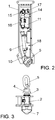
Figure 2 shows a longitudinal and lateral view of the fixture without one of its casings so it is possible to see the elements and components housed within it. -
Figure 3 shows a front elevation view of the fixture depicted infigure 1 . -
Figure 4 shows an exploded perspective view of the fixture's shaft with the nut and washer used to affix the same. -
Figure 5 shows an exploded perspective view of the extraction system that forms part of the invention fixture. - The aforementioned figures show that the automatic load-lifting fixture described herein consists of a prism-shaped and elongated general frame (1), on one end of which a shaft is mounted (2) horizontally, with a locknut (3) and a support (4) for an eyebolt (5) to which a shackle is attached (6), this being used to attach to the relevant lifting machine, while at the opposite end, there is a triangular cross-piece (7) to attach the load to be lifted, all the above by means of an extraction system (8) and an internal pneumatic cylinder (9) that attaches to the shaft (2) by means of a clevis and pin (10).
- In addition to the pneumatic cylinder (9), inside the casing (1) there is also an electronic board (11) and a battery system (12), which are set behind a side cover (13). In addition, there is a compressor (14), a pressure switch (15), a pneumatic valve (16) and a solenoid valve (17).
- Furthermore, and as can be seen in
figure 2 , the fixture includes an electric switch (18) and a lighting system (19) that is connected to the rechargeable battery (20), with manual operating buttons (21). -
Figure 4 shows the shaft (2), the end of which forms an angled cross-piece (7) and the locknut (3) with a washer (3') to effectively mount said shaft (2). There is also a support (22) and two components (23) that have concave sides that face each other and that are a means to extract said shaft, it being possible to attach and remove said components (23) using the screws located on the support (22).
Claims (7)
- Automatic load-lifting fixture is intended to be coupled to a lifting machine or device and to be attached to the load to be lifted and is characterised in that it consists of a prism-shaped general frame (1), on one end of which a shaft is mounted horizontally that can be removed (2) on one end of which there is an eyebolt (5) and shackle (6) to be coupled to the relevant lifting machine, while the other end of said shaft features a triangular cross-piece (7) to be attached to the load. Provision has been made to be able to rotate said shaft and to operate it automatically by electro-pneumatic or electro-hydraulic means and it is possible for the shaft to be in an open, closed or intermediate position. The means to attach the load can be operated manually, or via remote control.
- Automatic load-lifting fixture, according to claim 1, characterised in that the coupling shaft (2) is of an interchangeable nature so it can be attached to the right or left hand side of the general frame.
- Automatic load-lifting fixture, according to claim 1, characterised in that the frame houses a lighting system to give information about the position of the shaft, which may be open, closed or moving.
- Automatic load-lifting fixture, according to claim 1, characterised in that it features manual operating means that use switches to attach the load.
- Automatic load-lifting fixture, according to claim 1, characterised in that it includes a rechargeable battery that electrically powers the different elements involved in operating the fixture.
- Automatic load-lifting fixture, according to claim 1, characterised in that it includes a pneumatic cylinder (9) that is connected to the coupling shaft.
- Automatic load-lifting fixture, according to claim 1, characterised in that it has an extraction system for removing the shaft.
Applications Claiming Priority (1)
| Application Number | Priority Date | Filing Date | Title |
|---|---|---|---|
| PCT/ES2016/070387 WO2017198880A1 (en) | 2016-05-20 | 2016-05-20 | Automatic accessory for lifting loads |
Publications (3)
| Publication Number | Publication Date |
|---|---|
| EP3486206A1 true EP3486206A1 (en) | 2019-05-22 |
| EP3486206A4 EP3486206A4 (en) | 2020-05-06 |
| EP3486206B1 EP3486206B1 (en) | 2022-09-28 |
Family
ID=60325737
Family Applications (1)
| Application Number | Title | Priority Date | Filing Date |
|---|---|---|---|
| EP16902278.7A Active EP3486206B1 (en) | 2016-05-20 | 2016-05-20 | Automatic accessory for lifting loads |
Country Status (3)
| Country | Link |
|---|---|
| EP (1) | EP3486206B1 (en) |
| ES (1) | ES2934737T3 (en) |
| WO (1) | WO2017198880A1 (en) |
Family Cites Families (8)
| Publication number | Priority date | Publication date | Assignee | Title |
|---|---|---|---|---|
| US3046046A (en) * | 1958-12-22 | 1962-07-24 | Mansaver Ind Inc | Motor actuated rotary crane hook |
| US3171552A (en) * | 1962-11-05 | 1965-03-02 | Vulcan Iron Works | Pile driving apparatus |
| US4068878A (en) * | 1976-09-28 | 1978-01-17 | The United States Of America As Represented By The Secretary Of The Navy | Container lift coupling |
| JPS6034719Y2 (en) * | 1978-07-28 | 1985-10-16 | 小松フオ−クリフト株式会社 | Rotary hook device in ram device |
| SE506063C2 (en) * | 1996-02-23 | 1997-11-03 | Gunnar Hoernberg | Coupling device for coupling between crane and load to be raised |
| CA2765189C (en) * | 2009-06-22 | 2017-01-10 | Aoki Machinery Co., Ltd. | Lifting hook device |
| CN104176621B (en) * | 2014-08-11 | 2016-09-28 | 国绿空间模块装备(天津)有限公司 | The lift up rapidly system of building block |
| CN204508578U (en) * | 2015-03-30 | 2015-07-29 | 南通润邦重机有限公司 | A kind of high-mobility, multipurpose, wheeled vehicle rotary hook |
-
2016
- 2016-05-20 ES ES16902278T patent/ES2934737T3/en active Active
- 2016-05-20 WO PCT/ES2016/070387 patent/WO2017198880A1/en not_active Ceased
- 2016-05-20 EP EP16902278.7A patent/EP3486206B1/en active Active
Also Published As
| Publication number | Publication date |
|---|---|
| WO2017198880A1 (en) | 2017-11-23 |
| ES2934737T3 (en) | 2023-02-24 |
| EP3486206A4 (en) | 2020-05-06 |
| EP3486206B1 (en) | 2022-09-28 |
Similar Documents
| Publication | Publication Date | Title |
|---|---|---|
| EP2855339B1 (en) | Apparatuses and methods for providing high electrical resistance for aerial work platform components | |
| US5273333A (en) | Load hook assembly for multiple loads and method of load transport | |
| EP3649397B1 (en) | Airborne system for replacing modular lighting luminaire | |
| CN103274300B (en) | Intelligent distant control lorry-mounted crane | |
| US10837473B2 (en) | Hydraulic system | |
| EP4048620B1 (en) | A portable vacuum lifter system | |
| AU2013101706A4 (en) | Tow hitch | |
| CN108082508B (en) | Electric landing assisting device of unmanned helicopter | |
| EP3486206A1 (en) | Automatic accessory for lifting loads | |
| EP3294596A1 (en) | Braking device | |
| US7934757B2 (en) | Hydraulic crane-mounted remotely-controlled lifting device | |
| CH717981A2 (en) | Device and method for transporting loads, in particular using a drone. | |
| EP2974991B1 (en) | Device for collecting ferrous materials | |
| DE10011442A1 (en) | Forklift truck with vertically movable tow bar attachment bolt inside counterweight, has bolt moved using remote controlled actuator | |
| CN211472668U (en) | Swing ladder safety control system for electric shovel | |
| CN101830401A (en) | Crane safety mechanism control system | |
| US20060254532A1 (en) | Automatic animal chute system | |
| RU2007145484A (en) | HYDRAULIC ENGINES FOR OPERATING A SYSTEM AGAINST LOADING AND CONTROL OF IT IN CONTAINER CRANES | |
| CN114055351B (en) | Loading and unloading power assisting device for single leaf spring | |
| DE102015113923B4 (en) | Power-operated loading bridge with emergency release device | |
| WO2025262532A1 (en) | Equipment for applying an aircraft warning device on an overhead line cable of a power line | |
| EP3401170B1 (en) | Braking device | |
| RU2309113C1 (en) | Hoist pneumatic drive control device | |
| CN207141098U (en) | Prevent super trailer controlling organization in inclined gallery | |
| CN204981052U (en) | Emergency drop arm device and its high-altitude operation vehicle |
Legal Events
| Date | Code | Title | Description |
|---|---|---|---|
| STAA | Information on the status of an ep patent application or granted ep patent |
Free format text: STATUS: THE INTERNATIONAL PUBLICATION HAS BEEN MADE |
|
| PUAI | Public reference made under article 153(3) epc to a published international application that has entered the european phase |
Free format text: ORIGINAL CODE: 0009012 |
|
| STAA | Information on the status of an ep patent application or granted ep patent |
Free format text: STATUS: REQUEST FOR EXAMINATION WAS MADE |
|
| 17P | Request for examination filed |
Effective date: 20190325 |
|
| AK | Designated contracting states |
Kind code of ref document: A1 Designated state(s): AL AT BE BG CH CY CZ DE DK EE ES FI FR GB GR HR HU IE IS IT LI LT LU LV MC MK MT NL NO PL PT RO RS SE SI SK SM TR |
|
| AX | Request for extension of the european patent |
Extension state: BA ME |
|
| DAV | Request for validation of the european patent (deleted) | ||
| DAX | Request for extension of the european patent (deleted) | ||
| A4 | Supplementary search report drawn up and despatched |
Effective date: 20200406 |
|
| RIC1 | Information provided on ipc code assigned before grant |
Ipc: B66C 1/34 20060101ALI20200331BHEP Ipc: B66C 1/22 20060101AFI20200331BHEP Ipc: B66C 1/66 20060101ALI20200331BHEP |
|
| RIC1 | Information provided on ipc code assigned before grant |
Ipc: B66C 1/66 20060101ALI20211029BHEP Ipc: B66C 1/34 20060101ALI20211029BHEP Ipc: B66C 1/22 20060101AFI20211029BHEP |
|
| GRAP | Despatch of communication of intention to grant a patent |
Free format text: ORIGINAL CODE: EPIDOSNIGR1 |
|
| STAA | Information on the status of an ep patent application or granted ep patent |
Free format text: STATUS: GRANT OF PATENT IS INTENDED |
|
| INTG | Intention to grant announced |
Effective date: 20220504 |
|
| GRAS | Grant fee paid |
Free format text: ORIGINAL CODE: EPIDOSNIGR3 |
|
| GRAA | (expected) grant |
Free format text: ORIGINAL CODE: 0009210 |
|
| STAA | Information on the status of an ep patent application or granted ep patent |
Free format text: STATUS: THE PATENT HAS BEEN GRANTED |
|
| AK | Designated contracting states |
Kind code of ref document: B1 Designated state(s): AL AT BE BG CH CY CZ DE DK EE ES FI FR GB GR HR HU IE IS IT LI LT LU LV MC MK MT NL NO PL PT RO RS SE SI SK SM TR |
|
| REG | Reference to a national code |
Ref country code: GB Ref legal event code: FG4D |
|
| REG | Reference to a national code |
Ref country code: CH Ref legal event code: EP |
|
| REG | Reference to a national code |
Ref country code: DE Ref legal event code: R096 Ref document number: 602016075365 Country of ref document: DE |
|
| REG | Reference to a national code |
Ref country code: AT Ref legal event code: REF Ref document number: 1521134 Country of ref document: AT Kind code of ref document: T Effective date: 20221015 |
|
| REG | Reference to a national code |
Ref country code: IE Ref legal event code: FG4D |
|
| REG | Reference to a national code |
Ref country code: LT Ref legal event code: MG9D |
|
| PG25 | Lapsed in a contracting state [announced via postgrant information from national office to epo] |
Ref country code: SE Free format text: LAPSE BECAUSE OF FAILURE TO SUBMIT A TRANSLATION OF THE DESCRIPTION OR TO PAY THE FEE WITHIN THE PRESCRIBED TIME-LIMIT Effective date: 20220928 Ref country code: RS Free format text: LAPSE BECAUSE OF FAILURE TO SUBMIT A TRANSLATION OF THE DESCRIPTION OR TO PAY THE FEE WITHIN THE PRESCRIBED TIME-LIMIT Effective date: 20220928 Ref country code: NO Free format text: LAPSE BECAUSE OF FAILURE TO SUBMIT A TRANSLATION OF THE DESCRIPTION OR TO PAY THE FEE WITHIN THE PRESCRIBED TIME-LIMIT Effective date: 20221228 Ref country code: LV Free format text: LAPSE BECAUSE OF FAILURE TO SUBMIT A TRANSLATION OF THE DESCRIPTION OR TO PAY THE FEE WITHIN THE PRESCRIBED TIME-LIMIT Effective date: 20220928 Ref country code: LT Free format text: LAPSE BECAUSE OF FAILURE TO SUBMIT A TRANSLATION OF THE DESCRIPTION OR TO PAY THE FEE WITHIN THE PRESCRIBED TIME-LIMIT Effective date: 20220928 Ref country code: FI Free format text: LAPSE BECAUSE OF FAILURE TO SUBMIT A TRANSLATION OF THE DESCRIPTION OR TO PAY THE FEE WITHIN THE PRESCRIBED TIME-LIMIT Effective date: 20220928 |
|
| REG | Reference to a national code |
Ref country code: NL Ref legal event code: MP Effective date: 20220928 |
|
| REG | Reference to a national code |
Ref country code: AT Ref legal event code: MK05 Ref document number: 1521134 Country of ref document: AT Kind code of ref document: T Effective date: 20220928 |
|
| REG | Reference to a national code |
Ref country code: ES Ref legal event code: FG2A Ref document number: 2934737 Country of ref document: ES Kind code of ref document: T3 Effective date: 20230224 |
|
| PG25 | Lapsed in a contracting state [announced via postgrant information from national office to epo] |
Ref country code: HR Free format text: LAPSE BECAUSE OF FAILURE TO SUBMIT A TRANSLATION OF THE DESCRIPTION OR TO PAY THE FEE WITHIN THE PRESCRIBED TIME-LIMIT Effective date: 20220928 Ref country code: GR Free format text: LAPSE BECAUSE OF FAILURE TO SUBMIT A TRANSLATION OF THE DESCRIPTION OR TO PAY THE FEE WITHIN THE PRESCRIBED TIME-LIMIT Effective date: 20221229 |
|
| PG25 | Lapsed in a contracting state [announced via postgrant information from national office to epo] |
Ref country code: SM Free format text: LAPSE BECAUSE OF FAILURE TO SUBMIT A TRANSLATION OF THE DESCRIPTION OR TO PAY THE FEE WITHIN THE PRESCRIBED TIME-LIMIT Effective date: 20220928 Ref country code: RO Free format text: LAPSE BECAUSE OF FAILURE TO SUBMIT A TRANSLATION OF THE DESCRIPTION OR TO PAY THE FEE WITHIN THE PRESCRIBED TIME-LIMIT Effective date: 20220928 Ref country code: PT Free format text: LAPSE BECAUSE OF FAILURE TO SUBMIT A TRANSLATION OF THE DESCRIPTION OR TO PAY THE FEE WITHIN THE PRESCRIBED TIME-LIMIT Effective date: 20230130 Ref country code: CZ Free format text: LAPSE BECAUSE OF FAILURE TO SUBMIT A TRANSLATION OF THE DESCRIPTION OR TO PAY THE FEE WITHIN THE PRESCRIBED TIME-LIMIT Effective date: 20220928 Ref country code: AT Free format text: LAPSE BECAUSE OF FAILURE TO SUBMIT A TRANSLATION OF THE DESCRIPTION OR TO PAY THE FEE WITHIN THE PRESCRIBED TIME-LIMIT Effective date: 20220928 |
|
| PG25 | Lapsed in a contracting state [announced via postgrant information from national office to epo] |
Ref country code: SK Free format text: LAPSE BECAUSE OF FAILURE TO SUBMIT A TRANSLATION OF THE DESCRIPTION OR TO PAY THE FEE WITHIN THE PRESCRIBED TIME-LIMIT Effective date: 20220928 Ref country code: PL Free format text: LAPSE BECAUSE OF FAILURE TO SUBMIT A TRANSLATION OF THE DESCRIPTION OR TO PAY THE FEE WITHIN THE PRESCRIBED TIME-LIMIT Effective date: 20220928 Ref country code: IS Free format text: LAPSE BECAUSE OF FAILURE TO SUBMIT A TRANSLATION OF THE DESCRIPTION OR TO PAY THE FEE WITHIN THE PRESCRIBED TIME-LIMIT Effective date: 20230128 Ref country code: EE Free format text: LAPSE BECAUSE OF FAILURE TO SUBMIT A TRANSLATION OF THE DESCRIPTION OR TO PAY THE FEE WITHIN THE PRESCRIBED TIME-LIMIT Effective date: 20220928 |
|
| REG | Reference to a national code |
Ref country code: DE Ref legal event code: R097 Ref document number: 602016075365 Country of ref document: DE |
|
| PG25 | Lapsed in a contracting state [announced via postgrant information from national office to epo] |
Ref country code: NL Free format text: LAPSE BECAUSE OF FAILURE TO SUBMIT A TRANSLATION OF THE DESCRIPTION OR TO PAY THE FEE WITHIN THE PRESCRIBED TIME-LIMIT Effective date: 20220928 Ref country code: AL Free format text: LAPSE BECAUSE OF FAILURE TO SUBMIT A TRANSLATION OF THE DESCRIPTION OR TO PAY THE FEE WITHIN THE PRESCRIBED TIME-LIMIT Effective date: 20220928 |
|
| PG25 | Lapsed in a contracting state [announced via postgrant information from national office to epo] |
Ref country code: DK Free format text: LAPSE BECAUSE OF FAILURE TO SUBMIT A TRANSLATION OF THE DESCRIPTION OR TO PAY THE FEE WITHIN THE PRESCRIBED TIME-LIMIT Effective date: 20220928 |
|
| PLBE | No opposition filed within time limit |
Free format text: ORIGINAL CODE: 0009261 |
|
| STAA | Information on the status of an ep patent application or granted ep patent |
Free format text: STATUS: NO OPPOSITION FILED WITHIN TIME LIMIT |
|
| 26N | No opposition filed |
Effective date: 20230629 |
|
| PG25 | Lapsed in a contracting state [announced via postgrant information from national office to epo] |
Ref country code: SI Free format text: LAPSE BECAUSE OF FAILURE TO SUBMIT A TRANSLATION OF THE DESCRIPTION OR TO PAY THE FEE WITHIN THE PRESCRIBED TIME-LIMIT Effective date: 20220928 |
|
| REG | Reference to a national code |
Ref country code: CH Ref legal event code: PL |
|
| PG25 | Lapsed in a contracting state [announced via postgrant information from national office to epo] |
Ref country code: MC Free format text: LAPSE BECAUSE OF FAILURE TO SUBMIT A TRANSLATION OF THE DESCRIPTION OR TO PAY THE FEE WITHIN THE PRESCRIBED TIME-LIMIT Effective date: 20220928 |
|
| REG | Reference to a national code |
Ref country code: BE Ref legal event code: MM Effective date: 20230531 |
|
| PG25 | Lapsed in a contracting state [announced via postgrant information from national office to epo] |
Ref country code: MC Free format text: LAPSE BECAUSE OF FAILURE TO SUBMIT A TRANSLATION OF THE DESCRIPTION OR TO PAY THE FEE WITHIN THE PRESCRIBED TIME-LIMIT Effective date: 20220928 Ref country code: LU Free format text: LAPSE BECAUSE OF NON-PAYMENT OF DUE FEES Effective date: 20230520 Ref country code: LI Free format text: LAPSE BECAUSE OF NON-PAYMENT OF DUE FEES Effective date: 20230531 Ref country code: CH Free format text: LAPSE BECAUSE OF NON-PAYMENT OF DUE FEES Effective date: 20230531 |
|
| REG | Reference to a national code |
Ref country code: IE Ref legal event code: MM4A |
|
| PG25 | Lapsed in a contracting state [announced via postgrant information from national office to epo] |
Ref country code: IE Free format text: LAPSE BECAUSE OF NON-PAYMENT OF DUE FEES Effective date: 20230520 |
|
| PG25 | Lapsed in a contracting state [announced via postgrant information from national office to epo] |
Ref country code: IE Free format text: LAPSE BECAUSE OF NON-PAYMENT OF DUE FEES Effective date: 20230520 |
|
| PG25 | Lapsed in a contracting state [announced via postgrant information from national office to epo] |
Ref country code: IT Free format text: LAPSE BECAUSE OF FAILURE TO SUBMIT A TRANSLATION OF THE DESCRIPTION OR TO PAY THE FEE WITHIN THE PRESCRIBED TIME-LIMIT Effective date: 20220928 Ref country code: BE Free format text: LAPSE BECAUSE OF NON-PAYMENT OF DUE FEES Effective date: 20230531 |
|
| REG | Reference to a national code |
Ref country code: DE Ref legal event code: R081 Ref document number: 602016075365 Country of ref document: DE Owner name: HOOKS' TECH VANGUARD, S.L., ES Free format text: FORMER OWNER: HOOKS TANIA VERDU, S.L., CAMARGO, ES |
|
| PG25 | Lapsed in a contracting state [announced via postgrant information from national office to epo] |
Ref country code: BG Free format text: LAPSE BECAUSE OF FAILURE TO SUBMIT A TRANSLATION OF THE DESCRIPTION OR TO PAY THE FEE WITHIN THE PRESCRIBED TIME-LIMIT Effective date: 20220928 |
|
| PG25 | Lapsed in a contracting state [announced via postgrant information from national office to epo] |
Ref country code: BG Free format text: LAPSE BECAUSE OF FAILURE TO SUBMIT A TRANSLATION OF THE DESCRIPTION OR TO PAY THE FEE WITHIN THE PRESCRIBED TIME-LIMIT Effective date: 20220928 |
|
| PGFP | Annual fee paid to national office [announced via postgrant information from national office to epo] |
Ref country code: DE Payment date: 20250529 Year of fee payment: 10 |
|
| PGFP | Annual fee paid to national office [announced via postgrant information from national office to epo] |
Ref country code: GB Payment date: 20250527 Year of fee payment: 10 Ref country code: ES Payment date: 20250617 Year of fee payment: 10 |
|
| PGFP | Annual fee paid to national office [announced via postgrant information from national office to epo] |
Ref country code: FR Payment date: 20250526 Year of fee payment: 10 |
|
| PG25 | Lapsed in a contracting state [announced via postgrant information from national office to epo] |
Ref country code: CY Free format text: LAPSE BECAUSE OF FAILURE TO SUBMIT A TRANSLATION OF THE DESCRIPTION OR TO PAY THE FEE WITHIN THE PRESCRIBED TIME-LIMIT; INVALID AB INITIO Effective date: 20160520 |
|
| PG25 | Lapsed in a contracting state [announced via postgrant information from national office to epo] |
Ref country code: HU Free format text: LAPSE BECAUSE OF FAILURE TO SUBMIT A TRANSLATION OF THE DESCRIPTION OR TO PAY THE FEE WITHIN THE PRESCRIBED TIME-LIMIT; INVALID AB INITIO Effective date: 20160520 |
|
| PG25 | Lapsed in a contracting state [announced via postgrant information from national office to epo] |
Ref country code: TR Free format text: LAPSE BECAUSE OF FAILURE TO SUBMIT A TRANSLATION OF THE DESCRIPTION OR TO PAY THE FEE WITHIN THE PRESCRIBED TIME-LIMIT Effective date: 20220928 |