EP3486120B1 - Improved cycle carrier - Google Patents
Improved cycle carrier Download PDFInfo
- Publication number
- EP3486120B1 EP3486120B1 EP18203204.5A EP18203204A EP3486120B1 EP 3486120 B1 EP3486120 B1 EP 3486120B1 EP 18203204 A EP18203204 A EP 18203204A EP 3486120 B1 EP3486120 B1 EP 3486120B1
- Authority
- EP
- European Patent Office
- Prior art keywords
- segments
- cycle carrier
- designed
- segment
- joining element
- Prior art date
- Legal status (The legal status is an assumption and is not a legal conclusion. Google has not performed a legal analysis and makes no representation as to the accuracy of the status listed.)
- Active
Links
Images


Classifications
-
- B—PERFORMING OPERATIONS; TRANSPORTING
- B60—VEHICLES IN GENERAL
- B60R—VEHICLES, VEHICLE FITTINGS, OR VEHICLE PARTS, NOT OTHERWISE PROVIDED FOR
- B60R9/00—Supplementary fittings on vehicle exterior for carrying loads, e.g. luggage, sports gear or the like
- B60R9/04—Carriers associated with vehicle roof
- B60R9/048—Carriers characterised by article-gripping, -covering,-retaining, or -locking means
-
- B—PERFORMING OPERATIONS; TRANSPORTING
- B60—VEHICLES IN GENERAL
- B60R—VEHICLES, VEHICLE FITTINGS, OR VEHICLE PARTS, NOT OTHERWISE PROVIDED FOR
- B60R9/00—Supplementary fittings on vehicle exterior for carrying loads, e.g. luggage, sports gear or the like
- B60R9/08—Supplementary fittings on vehicle exterior for carrying loads, e.g. luggage, sports gear or the like specially adapted for sports gear
- B60R9/10—Supplementary fittings on vehicle exterior for carrying loads, e.g. luggage, sports gear or the like specially adapted for sports gear for cycles
Definitions
- This invention relates to a roof-mounted cycle carrier with increased utility.
- Cycle carriers are known which are mounted on the roof bars which can be fixed to the roof of the automobile.
- a prior art cycle carrier comprises a profile which is anchored transversely to the bars and is provided with an upper groove, which receives the tyres of the rear wheel of the bicycle.
- a difficulty encountered by the manufacturers and distributors of these products is the fact that the dimensions of the profiles of these cycle carriers are not easily managed by the logistics firms, who deliver these products.
- the most common size of the pallets is 80x120 cm, whilst the profiles are at least 1300 cm long; thus, for the purposes of delivering the cycle carriers, the manufacturers are forced to use special solutions with consequent added costs.
- DE202005012254 discloses a bicycle carrier, which includes two segments joined by mean of a joining element; the segments contact the joining element at the same side of the latter.
- the technical purpose which forms the basis of the invention is therefore to provide a roof cycle carrier which is simpler and less costly to despatch. This aim is achieved by the cycle carrier made according to claim 1.
- the numeral 1 denotes a roof cycle carrier made according to the invention.
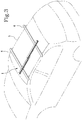
- the cycle carrier 1 proposed is designed to be mounted on the roof of a motor vehicle 5, preferably anchored so that it rests on the so-called "roof bars" 6, which are well known in the sector of carrying accessories for motor vehicles (see Figure 3 ).
- the invention comprises one or more elongate support elements 10, each designed to receive at least one of the tyres of a bicycle.
- Each support 1 of the cycle carrier comprises a plurality of segments 10, for example two, each of which may comprise a respective profile, preferably made of aluminium or other metal, which has a groove above for receiving the tyre.
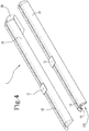
- the cycle carrier 1 has both a use configuration wherein the segments 10 of the support element 1 are joined to each other, preferably aligned, and a non-use configuration wherein the segments 10 are separated from each other and can be placed, stored and, more in detail, located on a pallet in side-by-side configuration (as schematically illustrated in Figure 4 ).
- the invention makes it possible to obtain a cycle carrier 1 which, in the use configuration, defines solid supports 1 for the bicycles, to be mounted, for example, on the "roof rack" 6 ( Figure 3 ), the supports 1 of which, in the non-use configuration, are separated into two pieces 10 which, arranged side by side, may then be placed on normal type pallets, for example 80x120 cm, without therefore requiring costly logistics solutions.
- Each segment 10 is preferably designed to receive a wheel of a bicycle.
- Each support element 1 comprises joining means 2, 3 for fixing the respective segments 10 to each other in a removable fashion, to allow changing from the use to the non-use configuration.
- the invention makes available a sort of kit consisting of two segments 10 and joining means 2, 3.
- the joining means 2 are preferably each equipped with a relative groove; in this way, in the use configuration where the segments 10 are aligned with each other by means of the joining means 2, the succession of grooves of the two segments 10 and the joining means 2, defines a guide for receiving the tyre which is substantially continuous (see for example Figure 2 ).
- the grooves of the two segments 10 are aligned and are joined by means of the groove of the joining means 2, so that it is a sort of composite groove or guide but which is substantially continuous in its extension.
- each segment 10 is designed to rest on the roof bars 6 (or other carrying systems) and comprises special coupling elements 11, also of known type, whilst the opposite upper side has the groove which, preferably, is defined for the entire length.
- the groove is formed in the upper side of it, whilst the coupling elements 11 are fixed to the opposite lower side.
- metal or plastic terminals may be applied at the ends of the profiles 10 which close the inner cavity, like a cap.
- the joining means 2 of the first embodiment comprise a joining element 20, which may be made of plastic or metal, equipped with two connecting parts, each designed to be fixed in a removable fashion to an end portion a relative segment 10.
- the joining element 20 can be made, for example, in a single piece and be suitably shaped to allow the connection between the segments 10 and in general perform the function of cycle carrier 1.
- the joining element 20 acts as an interface between the two segments 10 and more specifically between the profiles 10 of the two segments which form the support element 1.
- the joining element 20 is fixed in a releasable fashion to one of the two ends 110 of each segment 10, which can be defined as “inner”, rather than the "outer" free end.
- the joining element 20 is positioned centrally with respect to the supporting element 1 and connects the two inner end portions 110 of the respective segments 10, to define a single support 1 which is able to support the bicycle, in turn resting on the on the roof rack 6.
- the joining element 20 comprises two opposite sides 201, 202, upper and lower, each designed to come into contact with a different segment 10 in the above-mentioned use configuration; more precisely, the upper side 201 of the joining element 20 is the one which defines the relative groove.
- the above-mentioned parts of the joining element 20 which are fixed to the respective segment 10 are one upper and the other lower.
- the joining element 20 is positioned between the two segments 10 which it joins; preferably, the joining element 20 comprises a tapered end 200 designed to be inserted in the groove of one of the segments 10 in such a way as to extend it by the groove of the same joining element 20 (see for example Figures 2 and 7 ).
- the joining element 20 is mounted on one of the profiles 10, with a relative end tapered and shaped 200 which inserts into the groove of the profile 10.
- the end 200 is equipped with the groove of the joining element 20 which joins the groove of the lower profile and that of the profile mounted above the joining element 20, to define an upper guide which performs the same function as a single groove made in a single piece.
- the profile 10 of each segment matches at least one shaped engaging guide 12, 13, preferably for the full length.
- the guide 12, 13 may be a longitudinal cavity, provided with an axial opening groove, to form a "C" shape.
- the joining element 20 comprises two through holes 21, 22, made in two parts same element 2, in which can be inserted respective screws 23, 24 provided with a head suitably shaped to be inserted in the guide 12, 13 of one of the segments 10.
- the joining element 20 of the first embodiment of the invention is provided with two engaging members, which in the example shown are formed by the heads of the screws 23, 24, provided for coupling the respective profiles 10 to the guide 12, 13.
- a locknut 25, 26 is screwed at the end of the screw 23, 24 opposite the shaped head.
- each profile 10 comprises two shaped parallel guides 12, 13, of which one upper, made on the bottom of the groove, and the other lower, made on the lower side, separated from each other by a wall, with respect to which they are symmetrical (see Figures 5 - 7 ), to define an "H" profile.
- the screw 24 positioned in the part of the joining element 20 which has the tapered end 200 which is inserted in the groove of the profile 10 is located with the head facing downwards, that is to say, protruding from the lower side; in this way, the head of this screw 24 enters along the upper guide 13 of the profile 10.
- the other screw 23 is oriented with their head facing upwards, protruding from the upper side, in such a way that it can be inserted in the lower guide 12 of the respective profile 10.
- the joining element 20 may also comprise shoulders 27', 27, made on the two lower and upper sides, internally relative to the through holes, which act as end stops for inserting the profiles 10; in practice, the shoulders 27', 27 are used as a contact element of the inner end of the profiles 10 when they are coupled to the heads for engaging the guides.
- the joining means 3 comprise a joining element 30 different from that of the first embodiment, labelled 20 in the drawings.
- This alternative joining element 30 comprises an upper engaging side 31, 32, 33, to which is anchored in a removable fashion the segments 10 of the invention and a lower side, designed in use to face the roof of the vehicle 5.
- segments 10 of the second embodiment may be equal to those of the first embodiment or, alternatively, at least one of the profiles of a segment may have a curved shape for reasons which will be described in more detail below.
- the upper side of the joining element comprises two coupling surfaces 31, 33 designed to be removably joined to a respective segment 10; in any case, the joining surfaces 31, 33 are substantially facing the same direction, that is to say, in use, upwards and not downwards.
- These surfaces 31, 33 may be adjacent or, as in the preferential example shown in Figures 8 and 9 , may be separated and, for example, offset, that is to say, located on ideal planes distinct from each other, which can be parallel or incident.
- the connecting surfaces 31, 33 are joined by a transition surface 32.
- this joining element 30 is made by a plate, made of plastic or metal, forming three walls, or sub-plates or substantially planar elements, positioned in a "Z" Shape, that is to say, with an upper wall which defines the first coupling surface, labelled 31, a lower wall which defines the other coupling surface 33, and an intermediate wall, oblique or transversal relative to the upper and lower walls which joins them and defines the transition surface 32.
- the two segments 10 are spaced away from each other and also at two different heights, at least with regard to the respective pieces which are at the joining element 30 (see Figure 8 ).
- At least one of the two segments 10 and more precisely the relative piece mentioned above may be curved so as to compensate for the difference in level between the two segments 10, in such a way that the respective grooves can be on ideal planes which are not too far from each other, at least for a certain stretch of the respective length, to allow a correct placement of the wheels of the bicycle.
- the assembly of the cycle carriers 1 equipped with joining means 3 according to the second embodiment is not unlike the assembly of known cycle carriers.
- the segments 10 are removably joined to the joining element 30 by bolts, the thread of which passes through the holes labelled 33 and 34 in Figure 9 and in holes specially provided in segments 10.
- the joining element 30 couples to the profiles of the roof bars 6 by means of a mechanical a plate (not illustrated) shaped in such a way as to be inserted exactly in a groove of the profiles of the bars 6, which is coupled to the joining element 30 and is designed to clamp to the relative bar 6 by means of a lever mechanism (not shown in the drawings as it is of known type).
Landscapes
- Engineering & Computer Science (AREA)
- Mechanical Engineering (AREA)
- Fittings On The Vehicle Exterior For Carrying Loads, And Devices For Holding Or Mounting Articles (AREA)
Description
- This invention relates to a roof-mounted cycle carrier with increased utility. Cycle carriers are known which are mounted on the roof bars which can be fixed to the roof of the automobile.
- A prior art cycle carrier comprises a profile which is anchored transversely to the bars and is provided with an upper groove, which receives the tyres of the rear wheel of the bicycle.
- This type of cycle carrier has had great success on the market and is therefore in great demand in various countries.
- A difficulty encountered by the manufacturers and distributors of these products is the fact that the dimensions of the profiles of these cycle carriers are not easily managed by the logistics firms, who deliver these products.
- In effect, the most common size of the pallets is 80x120 cm, whilst the profiles are at least 1300 cm long; thus, for the purposes of delivering the cycle carriers, the manufacturers are forced to use special solutions with consequent added costs.
-
DE202005012254 discloses a bicycle carrier, which includes two segments joined by mean of a joining element; the segments contact the joining element at the same side of the latter. - The technical purpose which forms the basis of the invention is therefore to provide a roof cycle carrier which is simpler and less costly to despatch. This aim is achieved by the cycle carrier made according to
claim 1. - Further features and advantages of this invention are more apparent in the detailed description below, with reference to a preferred, non-restricting, embodiment of a cycle carrier as illustrated in the accompanying drawings, in which:
-
Figures 1 and 2 are axonometric views of a support of the cycle carrier according to a first embodiment of the invention, seen from above and below, respectively; -
Figure 3 is a schematic axonometric view of two cycle carriers mounted on the roof of a vehicle; -
Figure 4 is a view of two segments which make up the support ofFigures 1 and 2 , arranged side by side; -
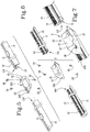
Figures 5 and 6 are exploded views of the support of the preceding drawings, seen from different points; -
Figure 7 is an axonometric view, partly exploded, of a detail of the invention; and -
Figures 8 and 9 are axonometric views which show a second embodiment not according to the invention, both exploded and assembled. - With reference to the accompanying drawings, the
numeral 1 denotes a roof cycle carrier made according to the invention. - The
cycle carrier 1 proposed is designed to be mounted on the roof of amotor vehicle 5, preferably anchored so that it rests on the so-called "roof bars" 6, which are well known in the sector of carrying accessories for motor vehicles (seeFigure 3 ). - The invention comprises one or more
elongate support elements 10, each designed to receive at least one of the tyres of a bicycle. - Each
support 1 of the cycle carrier comprises a plurality ofsegments 10, for example two, each of which may comprise a respective profile, preferably made of aluminium or other metal, which has a groove above for receiving the tyre. - Advantageously, the
cycle carrier 1 has both a use configuration wherein thesegments 10 of thesupport element 1 are joined to each other, preferably aligned, and a non-use configuration wherein thesegments 10 are separated from each other and can be placed, stored and, more in detail, located on a pallet in side-by-side configuration (as schematically illustrated inFigure 4 ). - In practice, the invention makes it possible to obtain a
cycle carrier 1 which, in the use configuration, definessolid supports 1 for the bicycles, to be mounted, for example, on the "roof rack" 6 (Figure 3 ), thesupports 1 of which, in the non-use configuration, are separated into twopieces 10 which, arranged side by side, may then be placed on normal type pallets, for example 80x120 cm, without therefore requiring costly logistics solutions. - Each
segment 10 is preferably designed to receive a wheel of a bicycle. Eachsupport element 1 comprises joiningmeans respective segments 10 to each other in a removable fashion, to allow changing from the use to the non-use configuration. - Preferably, the invention makes available a sort of kit consisting of two
segments 10 and joiningmeans - In a first embodiment, shown in
Figures 1 - 7 , thejoining means 2 are preferably each equipped with a relative groove; in this way, in the use configuration where thesegments 10 are aligned with each other by means of thejoining means 2, the succession of grooves of the twosegments 10 and the joiningmeans 2, defines a guide for receiving the tyre which is substantially continuous (see for exampleFigure 2 ). - In practice, in the preferential version of the invention, the grooves of the two
segments 10 are aligned and are joined by means of the groove of thejoining means 2, so that it is a sort of composite groove or guide but which is substantially continuous in its extension. - In even more detail, as may be seen in
Figures 4 to 7 , the lower side of eachsegment 10 is designed to rest on the roof bars 6 (or other carrying systems) and comprisesspecial coupling elements 11, also of known type, whilst the opposite upper side has the groove which, preferably, is defined for the entire length. - In the preferential case wherein the segments comprise a
profile 10, the groove is formed in the upper side of it, whilst thecoupling elements 11 are fixed to the opposite lower side. - The terms "upper" or "lower" used in this description refer to the orientation which the components of the invention adopt in use, when mounted on the vehicle, in the arrangement of
Figure 3 . - As in the example illustrated, metal or plastic terminals may be applied at the ends of the
profiles 10 which close the inner cavity, like a cap. - Preferably, the joining means 2 of the first embodiment comprise a joining
element 20, which may be made of plastic or metal, equipped with two connecting parts, each designed to be fixed in a removable fashion to an end portion arelative segment 10. - The joining
element 20 can be made, for example, in a single piece and be suitably shaped to allow the connection between thesegments 10 and in general perform the function ofcycle carrier 1. - In practice, the joining
element 20 acts as an interface between the twosegments 10 and more specifically between theprofiles 10 of the two segments which form thesupport element 1. - The joining
element 20 is fixed in a releasable fashion to one of the twoends 110 of eachsegment 10, which can be defined as "inner", rather than the "outer" free end. - For this reason, the joining
element 20 is positioned centrally with respect to the supportingelement 1 and connects the twoinner end portions 110 of therespective segments 10, to define asingle support 1 which is able to support the bicycle, in turn resting on the on theroof rack 6. - Still more in detail, the joining
element 20 comprises twoopposite sides 201, 202, upper and lower, each designed to come into contact with adifferent segment 10 in the above-mentioned use configuration; more precisely, the upper side 201 of the joiningelement 20 is the one which defines the relative groove. - For this reason, the above-mentioned parts of the joining
element 20 which are fixed to therespective segment 10 are one upper and the other lower. - In practice, in the use configuration, the joining
element 20 is positioned between the twosegments 10 which it joins; preferably, the joiningelement 20 comprises atapered end 200 designed to be inserted in the groove of one of thesegments 10 in such a way as to extend it by the groove of the same joining element 20 (see for exampleFigures 2 and7 ). - In other words, the joining
element 20 is mounted on one of theprofiles 10, with a relative end tapered and shaped 200 which inserts into the groove of theprofile 10. - The
end 200 is equipped with the groove of the joiningelement 20 which joins the groove of the lower profile and that of the profile mounted above the joiningelement 20, to define an upper guide which performs the same function as a single groove made in a single piece. - In a preferred embodiment, the
profile 10 of each segment matches at least one shapedengaging guide - In practice, the
guide - In the embodiment illustrated in the drawings, the joining
element 20 comprises two throughholes same element 2, in which can be insertedrespective screws guide segments 10. - In more general terms, the joining
element 20 of the first embodiment of the invention is provided with two engaging members, which in the example shown are formed by the heads of thescrews respective profiles 10 to theguide - Clearly, a
locknut screw - More specifically, each
profile 10 comprises two shapedparallel guides Figures 5 - 7 ), to define an "H" profile. - Basically, the
screw 24 positioned in the part of the joiningelement 20 which has thetapered end 200 which is inserted in the groove of theprofile 10 is located with the head facing downwards, that is to say, protruding from the lower side; in this way, the head of thisscrew 24 enters along theupper guide 13 of theprofile 10. - The
other screw 23 is oriented with their head facing upwards, protruding from the upper side, in such a way that it can be inserted in thelower guide 12 of therespective profile 10. - The joining
element 20 may also compriseshoulders 27', 27, made on the two lower and upper sides, internally relative to the through holes, which act as end stops for inserting theprofiles 10; in practice, theshoulders 27', 27 are used as a contact element of the inner end of theprofiles 10 when they are coupled to the heads for engaging the guides. - In a second embodiment, shown in
Figures 8 and 9 , the joining means 3 comprise a joiningelement 30 different from that of the first embodiment, labelled 20 in the drawings. - This
alternative joining element 30 comprises an upperengaging side segments 10 of the invention and a lower side, designed in use to face the roof of thevehicle 5. - It should be noted that the
segments 10 of the second embodiment, of which only parts are shown inFigures 8 and 9 , may be equal to those of the first embodiment or, alternatively, at least one of the profiles of a segment may have a curved shape for reasons which will be described in more detail below. - Preferably, the upper side of the joining element comprises two
coupling surfaces respective segment 10; in any case, thejoining surfaces - These
surfaces Figures 8 and 9 , may be separated and, for example, offset, that is to say, located on ideal planes distinct from each other, which can be parallel or incident. - More in detail, in the preferred version illustrated in the accompanying drawings, the connecting
surfaces transition surface 32. - Preferably, this joining
element 30 is made by a plate, made of plastic or metal, forming three walls, or sub-plates or substantially planar elements, positioned in a "Z" Shape, that is to say, with an upper wall which defines the first coupling surface, labelled 31, a lower wall which defines theother coupling surface 33, and an intermediate wall, oblique or transversal relative to the upper and lower walls which joins them and defines thetransition surface 32. - In this case, once connected to the
respective coupling surface segments 10 are spaced away from each other and also at two different heights, at least with regard to the respective pieces which are at the joining element 30 (seeFigure 8 ). - For this reason, at least one of the two
segments 10 and more precisely the relative piece mentioned above, may be curved so as to compensate for the difference in level between the twosegments 10, in such a way that the respective grooves can be on ideal planes which are not too far from each other, at least for a certain stretch of the respective length, to allow a correct placement of the wheels of the bicycle. - The assembly of the
cycle carriers 1 equipped withjoining means 3 according to the second embodiment is not unlike the assembly of known cycle carriers. - The
segments 10 are removably joined to the joiningelement 30 by bolts, the thread of which passes through the holes labelled 33 and 34 inFigure 9 and in holes specially provided insegments 10. - The joining
element 30 couples to the profiles of theroof bars 6 by means of a mechanical a plate (not illustrated) shaped in such a way as to be inserted exactly in a groove of the profiles of thebars 6, which is coupled to the joiningelement 30 and is designed to clamp to therelative bar 6 by means of a lever mechanism (not shown in the drawings as it is of known type).
Claims (9)
- A cycle carrier (1) comprising at least one elongate element (1) designed to receive a least one tyre of a bicycle and comprising a plurality of segments (10), wherein the cycle carrier (1) has a configuration of use wherein the segments (10) are joined together and a configuration of non-use wherein the segments (10) are separated from each other; wherein each segment (10) is designed to receive the tyre;
wherein joining means (2) are provided for fixing the segments (10) to each other, in a removable fashion;
wherein the joining means (2) comprise a joining element (20) equipped with two connecting parts each designed to be fixed in a removable fashion to an end portion (110) of a relative segment (10);
the cycle carrier (1) being characterized in that the joining element (20) comprises two opposite sides (201, 202), in use upper and lower, each designed to come into contact with a different segment (10) in the above-mentioned use configuration. - The cycle carrier (1) according to the preceding claim, wherein at least one of the segments (10) is equipped with an upper groove designed to receive the tyre.
- The cycle carrier (1) according to claim 1 and to the preceding claim, wherein the segments (10) and the joining means (2) are each equipped with a respective groove, the succession of aligned grooves defining a guide for receiving the tyre which is substantially continuous.
- The cycle carrier (1) according to claim 2 or 3, wherein each segment (10) comprises a lower side designed for resting on carrying systems such as roof bars or the like and an upper side in which the groove is made.
- The cycle carrier (1) according to any one of the preceding claims, wherein each segment comprises a profile (10).
- The cycle carrier (1) according to the preceding claim, wherein the upper side (201) of the joining element (20) comprises a relative groove.
- The cycle carrier (1) according to claim 1, wherein the profile (10) of each segment matches at least a shaped engaging guide (12, 13) and wherein the connecting parts of the joining element (20) each comprise a protruding engaging member designed to be inserted in the shaped guide of the relative segment (10).
- The cycle carrier (1) according to claim 1, wherein, in the use configuration, the joining element (20) is positioned between the two segments (10) which it joins.
- The cycle carrier (1) according to any one of claim 1, consisting of two segments (10) and joining means (2).
Applications Claiming Priority (1)
| Application Number | Priority Date | Filing Date | Title |
|---|---|---|---|
| IT201700131284 | 2017-11-16 |
Publications (2)
| Publication Number | Publication Date |
|---|---|
| EP3486120A1 EP3486120A1 (en) | 2019-05-22 |
| EP3486120B1 true EP3486120B1 (en) | 2020-06-17 |
Family
ID=64082999
Family Applications (1)
| Application Number | Title | Priority Date | Filing Date |
|---|---|---|---|
| EP18203204.5A Active EP3486120B1 (en) | 2017-11-16 | 2018-10-29 | Improved cycle carrier |
Country Status (1)
| Country | Link |
|---|---|
| EP (1) | EP3486120B1 (en) |
Family Cites Families (2)
| Publication number | Priority date | Publication date | Assignee | Title |
|---|---|---|---|---|
| DE29519438U1 (en) * | 1995-12-08 | 1996-05-23 | Beutenmüller, Frank, Dipl.-Ing., 70191 Stuttgart | Construction of a new roof rack for bicycle transport |
| DE202005012254U1 (en) * | 2005-08-04 | 2005-10-13 | Pozzi, Carlo Maurizio | Transport rail for cycle carrier mounted on vehicle has at least two longitudinal sections and a connection arrangement for connecting the longitudinal sections when desired |
-
2018
- 2018-10-29 EP EP18203204.5A patent/EP3486120B1/en active Active
Non-Patent Citations (1)
| Title |
|---|
| None * |
Also Published As
| Publication number | Publication date |
|---|---|
| EP3486120A1 (en) | 2019-05-22 |
Similar Documents
| Publication | Publication Date | Title |
|---|---|---|
| US6340186B2 (en) | Injection molded components for off-road recreational and utility vehicles | |
| EP2733050B1 (en) | Modular vehicle chassis frame | |
| US20220144365A1 (en) | Fender and fender assembly for a cycling apparatus | |
| US20140353350A1 (en) | Roof rail for a motor vehicle | |
| EP3486120B1 (en) | Improved cycle carrier | |
| US20080000940A1 (en) | Bicycle rack connection to roof rack of vehicles | |
| EP3858678B1 (en) | Crossbar and coupling member for a crossbar | |
| KR20090095131A (en) | Side rail bar insert integrated fashion loop carrier | |
| CN201201672Y (en) | Mudguard for vehicle | |
| CN215245320U (en) | Rear bottom fork and electric vehicle | |
| CN208344101U (en) | A kind of roof-rack | |
| US7380872B2 (en) | Wheeled vehicle with covers | |
| US20070215565A1 (en) | Positioning device for a rack on the rear of a vehicle | |
| CN214929344U (en) | Car running-board and car | |
| NL1018078C2 (en) | Mudguard made of plastic. | |
| JP7008003B2 (en) | Seat clamp and bicycle with it | |
| AU2013211025B2 (en) | Plate element for guiding a rail and method for producing said plate element | |
| CN215971877U (en) | Injection molding rear mudguard of electric bicycle | |
| EP1999006B1 (en) | Bicycle child seat mounting assembly | |
| EP1762471A2 (en) | Mudguard system for a cycle | |
| DE102017000834A1 (en) | Two-wheeled luggage carrier system as well as connectors | |
| CN220315217U (en) | Front fork mandrel protection structure | |
| CN203305931U (en) | Detachable license frame applied to bicycle frame at rear of car | |
| CN223253139U (en) | A conveniently adjustable bicycle parking rack | |
| CN101482196A (en) | Improved structure of cable bridge rack |
Legal Events
| Date | Code | Title | Description |
|---|---|---|---|
| PUAI | Public reference made under article 153(3) epc to a published international application that has entered the european phase |
Free format text: ORIGINAL CODE: 0009012 |
|
| STAA | Information on the status of an ep patent application or granted ep patent |
Free format text: STATUS: THE APPLICATION HAS BEEN PUBLISHED |
|
| AK | Designated contracting states |
Kind code of ref document: A1 Designated state(s): AL AT BE BG CH CY CZ DE DK EE ES FI FR GB GR HR HU IE IS IT LI LT LU LV MC MK MT NL NO PL PT RO RS SE SI SK SM TR |
|
| AX | Request for extension of the european patent |
Extension state: BA ME |
|
| STAA | Information on the status of an ep patent application or granted ep patent |
Free format text: STATUS: REQUEST FOR EXAMINATION WAS MADE |
|
| 17P | Request for examination filed |
Effective date: 20191107 |
|
| RBV | Designated contracting states (corrected) |
Designated state(s): AL AT BE BG CH CY CZ DE DK EE ES FI FR GB GR HR HU IE IS IT LI LT LU LV MC MK MT NL NO PL PT RO RS SE SI SK SM TR |
|
| RIC1 | Information provided on ipc code assigned before grant |
Ipc: B60R 9/048 20060101AFI20191216BHEP Ipc: B60R 9/10 20060101ALI20191216BHEP |
|
| GRAP | Despatch of communication of intention to grant a patent |
Free format text: ORIGINAL CODE: EPIDOSNIGR1 |
|
| STAA | Information on the status of an ep patent application or granted ep patent |
Free format text: STATUS: GRANT OF PATENT IS INTENDED |
|
| INTG | Intention to grant announced |
Effective date: 20200129 |
|
| RIN1 | Information on inventor provided before grant (corrected) |
Inventor name: SALSI, ANDREA |
|
| GRAS | Grant fee paid |
Free format text: ORIGINAL CODE: EPIDOSNIGR3 |
|
| GRAA | (expected) grant |
Free format text: ORIGINAL CODE: 0009210 |
|
| STAA | Information on the status of an ep patent application or granted ep patent |
Free format text: STATUS: THE PATENT HAS BEEN GRANTED |
|
| AK | Designated contracting states |
Kind code of ref document: B1 Designated state(s): AL AT BE BG CH CY CZ DE DK EE ES FI FR GB GR HR HU IE IS IT LI LT LU LV MC MK MT NL NO PL PT RO RS SE SI SK SM TR |
|
| REG | Reference to a national code |
Ref country code: GB Ref legal event code: FG4D |
|
| REG | Reference to a national code |
Ref country code: CH Ref legal event code: EP |
|
| REG | Reference to a national code |
Ref country code: IE Ref legal event code: FG4D |
|
| REG | Reference to a national code |
Ref country code: DE Ref legal event code: R096 Ref document number: 602018005379 Country of ref document: DE |
|
| REG | Reference to a national code |
Ref country code: AT Ref legal event code: REF Ref document number: 1280922 Country of ref document: AT Kind code of ref document: T Effective date: 20200715 |
|
| PG25 | Lapsed in a contracting state [announced via postgrant information from national office to epo] |
Ref country code: NO Free format text: LAPSE BECAUSE OF FAILURE TO SUBMIT A TRANSLATION OF THE DESCRIPTION OR TO PAY THE FEE WITHIN THE PRESCRIBED TIME-LIMIT Effective date: 20200917 Ref country code: FI Free format text: LAPSE BECAUSE OF FAILURE TO SUBMIT A TRANSLATION OF THE DESCRIPTION OR TO PAY THE FEE WITHIN THE PRESCRIBED TIME-LIMIT Effective date: 20200617 Ref country code: GR Free format text: LAPSE BECAUSE OF FAILURE TO SUBMIT A TRANSLATION OF THE DESCRIPTION OR TO PAY THE FEE WITHIN THE PRESCRIBED TIME-LIMIT Effective date: 20200918 Ref country code: LT Free format text: LAPSE BECAUSE OF FAILURE TO SUBMIT A TRANSLATION OF THE DESCRIPTION OR TO PAY THE FEE WITHIN THE PRESCRIBED TIME-LIMIT Effective date: 20200617 Ref country code: SE Free format text: LAPSE BECAUSE OF FAILURE TO SUBMIT A TRANSLATION OF THE DESCRIPTION OR TO PAY THE FEE WITHIN THE PRESCRIBED TIME-LIMIT Effective date: 20200617 |
|
| REG | Reference to a national code |
Ref country code: LT Ref legal event code: MG4D |
|
| REG | Reference to a national code |
Ref country code: NL Ref legal event code: MP Effective date: 20200617 |
|
| PG25 | Lapsed in a contracting state [announced via postgrant information from national office to epo] |
Ref country code: RS Free format text: LAPSE BECAUSE OF FAILURE TO SUBMIT A TRANSLATION OF THE DESCRIPTION OR TO PAY THE FEE WITHIN THE PRESCRIBED TIME-LIMIT Effective date: 20200617 Ref country code: HR Free format text: LAPSE BECAUSE OF FAILURE TO SUBMIT A TRANSLATION OF THE DESCRIPTION OR TO PAY THE FEE WITHIN THE PRESCRIBED TIME-LIMIT Effective date: 20200617 Ref country code: LV Free format text: LAPSE BECAUSE OF FAILURE TO SUBMIT A TRANSLATION OF THE DESCRIPTION OR TO PAY THE FEE WITHIN THE PRESCRIBED TIME-LIMIT Effective date: 20200617 Ref country code: BG Free format text: LAPSE BECAUSE OF FAILURE TO SUBMIT A TRANSLATION OF THE DESCRIPTION OR TO PAY THE FEE WITHIN THE PRESCRIBED TIME-LIMIT Effective date: 20200917 |
|
| REG | Reference to a national code |
Ref country code: AT Ref legal event code: MK05 Ref document number: 1280922 Country of ref document: AT Kind code of ref document: T Effective date: 20200617 |
|
| PG25 | Lapsed in a contracting state [announced via postgrant information from national office to epo] |
Ref country code: NL Free format text: LAPSE BECAUSE OF FAILURE TO SUBMIT A TRANSLATION OF THE DESCRIPTION OR TO PAY THE FEE WITHIN THE PRESCRIBED TIME-LIMIT Effective date: 20200617 Ref country code: AL Free format text: LAPSE BECAUSE OF FAILURE TO SUBMIT A TRANSLATION OF THE DESCRIPTION OR TO PAY THE FEE WITHIN THE PRESCRIBED TIME-LIMIT Effective date: 20200617 |
|
| PG25 | Lapsed in a contracting state [announced via postgrant information from national office to epo] |
Ref country code: PT Free format text: LAPSE BECAUSE OF FAILURE TO SUBMIT A TRANSLATION OF THE DESCRIPTION OR TO PAY THE FEE WITHIN THE PRESCRIBED TIME-LIMIT Effective date: 20201019 Ref country code: AT Free format text: LAPSE BECAUSE OF FAILURE TO SUBMIT A TRANSLATION OF THE DESCRIPTION OR TO PAY THE FEE WITHIN THE PRESCRIBED TIME-LIMIT Effective date: 20200617 Ref country code: RO Free format text: LAPSE BECAUSE OF FAILURE TO SUBMIT A TRANSLATION OF THE DESCRIPTION OR TO PAY THE FEE WITHIN THE PRESCRIBED TIME-LIMIT Effective date: 20200617 Ref country code: ES Free format text: LAPSE BECAUSE OF FAILURE TO SUBMIT A TRANSLATION OF THE DESCRIPTION OR TO PAY THE FEE WITHIN THE PRESCRIBED TIME-LIMIT Effective date: 20200617 Ref country code: CZ Free format text: LAPSE BECAUSE OF FAILURE TO SUBMIT A TRANSLATION OF THE DESCRIPTION OR TO PAY THE FEE WITHIN THE PRESCRIBED TIME-LIMIT Effective date: 20200617 Ref country code: SM Free format text: LAPSE BECAUSE OF FAILURE TO SUBMIT A TRANSLATION OF THE DESCRIPTION OR TO PAY THE FEE WITHIN THE PRESCRIBED TIME-LIMIT Effective date: 20200617 Ref country code: EE Free format text: LAPSE BECAUSE OF FAILURE TO SUBMIT A TRANSLATION OF THE DESCRIPTION OR TO PAY THE FEE WITHIN THE PRESCRIBED TIME-LIMIT Effective date: 20200617 |
|
| PG25 | Lapsed in a contracting state [announced via postgrant information from national office to epo] |
Ref country code: PL Free format text: LAPSE BECAUSE OF FAILURE TO SUBMIT A TRANSLATION OF THE DESCRIPTION OR TO PAY THE FEE WITHIN THE PRESCRIBED TIME-LIMIT Effective date: 20200617 Ref country code: SK Free format text: LAPSE BECAUSE OF FAILURE TO SUBMIT A TRANSLATION OF THE DESCRIPTION OR TO PAY THE FEE WITHIN THE PRESCRIBED TIME-LIMIT Effective date: 20200617 Ref country code: IS Free format text: LAPSE BECAUSE OF FAILURE TO SUBMIT A TRANSLATION OF THE DESCRIPTION OR TO PAY THE FEE WITHIN THE PRESCRIBED TIME-LIMIT Effective date: 20201017 |
|
| REG | Reference to a national code |
Ref country code: DE Ref legal event code: R097 Ref document number: 602018005379 Country of ref document: DE |
|
| PLBE | No opposition filed within time limit |
Free format text: ORIGINAL CODE: 0009261 |
|
| STAA | Information on the status of an ep patent application or granted ep patent |
Free format text: STATUS: NO OPPOSITION FILED WITHIN TIME LIMIT |
|
| PG25 | Lapsed in a contracting state [announced via postgrant information from national office to epo] |
Ref country code: DK Free format text: LAPSE BECAUSE OF FAILURE TO SUBMIT A TRANSLATION OF THE DESCRIPTION OR TO PAY THE FEE WITHIN THE PRESCRIBED TIME-LIMIT Effective date: 20200617 |
|
| 26N | No opposition filed |
Effective date: 20210318 |
|
| PG25 | Lapsed in a contracting state [announced via postgrant information from national office to epo] |
Ref country code: SI Free format text: LAPSE BECAUSE OF FAILURE TO SUBMIT A TRANSLATION OF THE DESCRIPTION OR TO PAY THE FEE WITHIN THE PRESCRIBED TIME-LIMIT Effective date: 20200617 |
|
| PG25 | Lapsed in a contracting state [announced via postgrant information from national office to epo] |
Ref country code: MC Free format text: LAPSE BECAUSE OF FAILURE TO SUBMIT A TRANSLATION OF THE DESCRIPTION OR TO PAY THE FEE WITHIN THE PRESCRIBED TIME-LIMIT Effective date: 20200617 Ref country code: LU Free format text: LAPSE BECAUSE OF NON-PAYMENT OF DUE FEES Effective date: 20201029 |
|
| REG | Reference to a national code |
Ref country code: BE Ref legal event code: MM Effective date: 20201031 |
|
| PG25 | Lapsed in a contracting state [announced via postgrant information from national office to epo] |
Ref country code: BE Free format text: LAPSE BECAUSE OF NON-PAYMENT OF DUE FEES Effective date: 20201031 |
|
| PG25 | Lapsed in a contracting state [announced via postgrant information from national office to epo] |
Ref country code: IE Free format text: LAPSE BECAUSE OF NON-PAYMENT OF DUE FEES Effective date: 20201029 |
|
| REG | Reference to a national code |
Ref country code: CH Ref legal event code: PL |
|
| PG25 | Lapsed in a contracting state [announced via postgrant information from national office to epo] |
Ref country code: TR Free format text: LAPSE BECAUSE OF FAILURE TO SUBMIT A TRANSLATION OF THE DESCRIPTION OR TO PAY THE FEE WITHIN THE PRESCRIBED TIME-LIMIT Effective date: 20200617 Ref country code: MT Free format text: LAPSE BECAUSE OF FAILURE TO SUBMIT A TRANSLATION OF THE DESCRIPTION OR TO PAY THE FEE WITHIN THE PRESCRIBED TIME-LIMIT Effective date: 20200617 Ref country code: CY Free format text: LAPSE BECAUSE OF FAILURE TO SUBMIT A TRANSLATION OF THE DESCRIPTION OR TO PAY THE FEE WITHIN THE PRESCRIBED TIME-LIMIT Effective date: 20200617 |
|
| PG25 | Lapsed in a contracting state [announced via postgrant information from national office to epo] |
Ref country code: MK Free format text: LAPSE BECAUSE OF FAILURE TO SUBMIT A TRANSLATION OF THE DESCRIPTION OR TO PAY THE FEE WITHIN THE PRESCRIBED TIME-LIMIT Effective date: 20200617 |
|
| PG25 | Lapsed in a contracting state [announced via postgrant information from national office to epo] |
Ref country code: LI Free format text: LAPSE BECAUSE OF NON-PAYMENT OF DUE FEES Effective date: 20211031 Ref country code: CH Free format text: LAPSE BECAUSE OF NON-PAYMENT OF DUE FEES Effective date: 20211031 |
|
| P01 | Opt-out of the competence of the unified patent court (upc) registered |
Effective date: 20230523 |
|
| PGFP | Annual fee paid to national office [announced via postgrant information from national office to epo] |
Ref country code: GB Payment date: 20231024 Year of fee payment: 6 |
|
| PGFP | Annual fee paid to national office [announced via postgrant information from national office to epo] |
Ref country code: IT Payment date: 20231027 Year of fee payment: 6 Ref country code: FR Payment date: 20231026 Year of fee payment: 6 Ref country code: DE Payment date: 20231027 Year of fee payment: 6 |
|
| REG | Reference to a national code |
Ref country code: DE Ref legal event code: R119 Ref document number: 602018005379 Country of ref document: DE |
|
| GBPC | Gb: european patent ceased through non-payment of renewal fee |
Effective date: 20241029 |
|
| PG25 | Lapsed in a contracting state [announced via postgrant information from national office to epo] |
Ref country code: DE Free format text: LAPSE BECAUSE OF NON-PAYMENT OF DUE FEES Effective date: 20250501 |
|
| PG25 | Lapsed in a contracting state [announced via postgrant information from national office to epo] |
Ref country code: GB Free format text: LAPSE BECAUSE OF NON-PAYMENT OF DUE FEES Effective date: 20241029 |
|
| PG25 | Lapsed in a contracting state [announced via postgrant information from national office to epo] |
Ref country code: FR Free format text: LAPSE BECAUSE OF NON-PAYMENT OF DUE FEES Effective date: 20241031 |
|
| PG25 | Lapsed in a contracting state [announced via postgrant information from national office to epo] |
Ref country code: IT Free format text: LAPSE BECAUSE OF NON-PAYMENT OF DUE FEES Effective date: 20241029 |