EP3486109A1 - Work vehicle and work vehicle management system - Google Patents
Work vehicle and work vehicle management system Download PDFInfo
- Publication number
- EP3486109A1 EP3486109A1 EP18177238.5A EP18177238A EP3486109A1 EP 3486109 A1 EP3486109 A1 EP 3486109A1 EP 18177238 A EP18177238 A EP 18177238A EP 3486109 A1 EP3486109 A1 EP 3486109A1
- Authority
- EP
- European Patent Office
- Prior art keywords
- battery
- work
- work vehicle
- information
- data
- Prior art date
- Legal status (The legal status is an assumption and is not a legal conclusion. Google has not performed a legal analysis and makes no representation as to the accuracy of the status listed.)
- Granted
Links
Images
Classifications
-
- G—PHYSICS
- G07—CHECKING-DEVICES
- G07C—TIME OR ATTENDANCE REGISTERS; REGISTERING OR INDICATING THE WORKING OF MACHINES; GENERATING RANDOM NUMBERS; VOTING OR LOTTERY APPARATUS; ARRANGEMENTS, SYSTEMS OR APPARATUS FOR CHECKING NOT PROVIDED FOR ELSEWHERE
- G07C5/00—Registering or indicating the working of vehicles
- G07C5/02—Registering or indicating driving, working, idle, or waiting time only
- G07C5/04—Registering or indicating driving, working, idle, or waiting time only using counting means or digital clocks
-
- A—HUMAN NECESSITIES
- A01—AGRICULTURE; FORESTRY; ANIMAL HUSBANDRY; HUNTING; TRAPPING; FISHING
- A01D—HARVESTING; MOWING
- A01D34/00—Mowers; Mowing apparatus of harvesters
- A01D34/006—Control or measuring arrangements
-
- A—HUMAN NECESSITIES
- A01—AGRICULTURE; FORESTRY; ANIMAL HUSBANDRY; HUNTING; TRAPPING; FISHING
- A01D—HARVESTING; MOWING
- A01D69/00—Driving mechanisms or parts thereof for harvesters or mowers
- A01D69/02—Driving mechanisms or parts thereof for harvesters or mowers electric
-
- B—PERFORMING OPERATIONS; TRANSPORTING
- B60—VEHICLES IN GENERAL
- B60L—PROPULSION OF ELECTRICALLY-PROPELLED VEHICLES; SUPPLYING ELECTRIC POWER FOR AUXILIARY EQUIPMENT OF ELECTRICALLY-PROPELLED VEHICLES; ELECTRODYNAMIC BRAKE SYSTEMS FOR VEHICLES IN GENERAL; MAGNETIC SUSPENSION OR LEVITATION FOR VEHICLES; MONITORING OPERATING VARIABLES OF ELECTRICALLY-PROPELLED VEHICLES; ELECTRIC SAFETY DEVICES FOR ELECTRICALLY-PROPELLED VEHICLES
- B60L3/00—Electric devices on electrically-propelled vehicles for safety purposes; Monitoring operating variables, e.g. speed, deceleration or energy consumption
- B60L3/12—Recording operating variables ; Monitoring of operating variables
-
- B—PERFORMING OPERATIONS; TRANSPORTING
- B60—VEHICLES IN GENERAL
- B60L—PROPULSION OF ELECTRICALLY-PROPELLED VEHICLES; SUPPLYING ELECTRIC POWER FOR AUXILIARY EQUIPMENT OF ELECTRICALLY-PROPELLED VEHICLES; ELECTRODYNAMIC BRAKE SYSTEMS FOR VEHICLES IN GENERAL; MAGNETIC SUSPENSION OR LEVITATION FOR VEHICLES; MONITORING OPERATING VARIABLES OF ELECTRICALLY-PROPELLED VEHICLES; ELECTRIC SAFETY DEVICES FOR ELECTRICALLY-PROPELLED VEHICLES
- B60L58/00—Methods or circuit arrangements for monitoring or controlling batteries or fuel cells, specially adapted for electric vehicles
- B60L58/10—Methods or circuit arrangements for monitoring or controlling batteries or fuel cells, specially adapted for electric vehicles for monitoring or controlling batteries
- B60L58/12—Methods or circuit arrangements for monitoring or controlling batteries or fuel cells, specially adapted for electric vehicles for monitoring or controlling batteries responding to state of charge [SoC]
-
- B—PERFORMING OPERATIONS; TRANSPORTING
- B60—VEHICLES IN GENERAL
- B60L—PROPULSION OF ELECTRICALLY-PROPELLED VEHICLES; SUPPLYING ELECTRIC POWER FOR AUXILIARY EQUIPMENT OF ELECTRICALLY-PROPELLED VEHICLES; ELECTRODYNAMIC BRAKE SYSTEMS FOR VEHICLES IN GENERAL; MAGNETIC SUSPENSION OR LEVITATION FOR VEHICLES; MONITORING OPERATING VARIABLES OF ELECTRICALLY-PROPELLED VEHICLES; ELECTRIC SAFETY DEVICES FOR ELECTRICALLY-PROPELLED VEHICLES
- B60L58/00—Methods or circuit arrangements for monitoring or controlling batteries or fuel cells, specially adapted for electric vehicles
- B60L58/10—Methods or circuit arrangements for monitoring or controlling batteries or fuel cells, specially adapted for electric vehicles for monitoring or controlling batteries
- B60L58/16—Methods or circuit arrangements for monitoring or controlling batteries or fuel cells, specially adapted for electric vehicles for monitoring or controlling batteries responding to battery ageing, e.g. to the number of charging cycles or the state of health [SoH]
-
- G—PHYSICS
- G07—CHECKING-DEVICES
- G07C—TIME OR ATTENDANCE REGISTERS; REGISTERING OR INDICATING THE WORKING OF MACHINES; GENERATING RANDOM NUMBERS; VOTING OR LOTTERY APPARATUS; ARRANGEMENTS, SYSTEMS OR APPARATUS FOR CHECKING NOT PROVIDED FOR ELSEWHERE
- G07C5/00—Registering or indicating the working of vehicles
- G07C5/008—Registering or indicating the working of vehicles communicating information to a remotely located station
-
- H—ELECTRICITY
- H01—ELECTRIC ELEMENTS
- H01M—PROCESSES OR MEANS, e.g. BATTERIES, FOR THE DIRECT CONVERSION OF CHEMICAL ENERGY INTO ELECTRICAL ENERGY
- H01M10/00—Secondary cells; Manufacture thereof
- H01M10/42—Methods or arrangements for servicing or maintenance of secondary cells or secondary half-cells
- H01M10/425—Structural combination with electronic components, e.g. electronic circuits integrated to the outside of the casing
-
- H—ELECTRICITY
- H01—ELECTRIC ELEMENTS
- H01M—PROCESSES OR MEANS, e.g. BATTERIES, FOR THE DIRECT CONVERSION OF CHEMICAL ENERGY INTO ELECTRICAL ENERGY
- H01M10/00—Secondary cells; Manufacture thereof
- H01M10/42—Methods or arrangements for servicing or maintenance of secondary cells or secondary half-cells
- H01M10/48—Accumulators combined with arrangements for measuring, testing or indicating the condition of cells, e.g. the level or density of the electrolyte
- H01M10/486—Accumulators combined with arrangements for measuring, testing or indicating the condition of cells, e.g. the level or density of the electrolyte for measuring temperature
-
- A—HUMAN NECESSITIES
- A01—AGRICULTURE; FORESTRY; ANIMAL HUSBANDRY; HUNTING; TRAPPING; FISHING
- A01D—HARVESTING; MOWING
- A01D2101/00—Lawn-mowers
-
- A—HUMAN NECESSITIES
- A01—AGRICULTURE; FORESTRY; ANIMAL HUSBANDRY; HUNTING; TRAPPING; FISHING
- A01D—HARVESTING; MOWING
- A01D34/00—Mowers; Mowing apparatus of harvesters
- A01D34/01—Mowers; Mowing apparatus of harvesters characterised by features relating to the type of cutting apparatus
- A01D34/412—Mowers; Mowing apparatus of harvesters characterised by features relating to the type of cutting apparatus having rotating cutters
- A01D34/63—Mowers; Mowing apparatus of harvesters characterised by features relating to the type of cutting apparatus having rotating cutters having cutters rotating about a vertical axis
- A01D34/64—Mowers; Mowing apparatus of harvesters characterised by features relating to the type of cutting apparatus having rotating cutters having cutters rotating about a vertical axis mounted on a vehicle, e.g. a tractor, or drawn by an animal or a vehicle
- A01D34/66—Mowers; Mowing apparatus of harvesters characterised by features relating to the type of cutting apparatus having rotating cutters having cutters rotating about a vertical axis mounted on a vehicle, e.g. a tractor, or drawn by an animal or a vehicle with two or more cutters
-
- B—PERFORMING OPERATIONS; TRANSPORTING
- B60—VEHICLES IN GENERAL
- B60L—PROPULSION OF ELECTRICALLY-PROPELLED VEHICLES; SUPPLYING ELECTRIC POWER FOR AUXILIARY EQUIPMENT OF ELECTRICALLY-PROPELLED VEHICLES; ELECTRODYNAMIC BRAKE SYSTEMS FOR VEHICLES IN GENERAL; MAGNETIC SUSPENSION OR LEVITATION FOR VEHICLES; MONITORING OPERATING VARIABLES OF ELECTRICALLY-PROPELLED VEHICLES; ELECTRIC SAFETY DEVICES FOR ELECTRICALLY-PROPELLED VEHICLES
- B60L2240/00—Control parameters of input or output; Target parameters
- B60L2240/40—Drive Train control parameters
- B60L2240/54—Drive Train control parameters related to batteries
- B60L2240/545—Temperature
-
- B—PERFORMING OPERATIONS; TRANSPORTING
- B60—VEHICLES IN GENERAL
- B60L—PROPULSION OF ELECTRICALLY-PROPELLED VEHICLES; SUPPLYING ELECTRIC POWER FOR AUXILIARY EQUIPMENT OF ELECTRICALLY-PROPELLED VEHICLES; ELECTRODYNAMIC BRAKE SYSTEMS FOR VEHICLES IN GENERAL; MAGNETIC SUSPENSION OR LEVITATION FOR VEHICLES; MONITORING OPERATING VARIABLES OF ELECTRICALLY-PROPELLED VEHICLES; ELECTRIC SAFETY DEVICES FOR ELECTRICALLY-PROPELLED VEHICLES
- B60L2240/00—Control parameters of input or output; Target parameters
- B60L2240/40—Drive Train control parameters
- B60L2240/54—Drive Train control parameters related to batteries
- B60L2240/547—Voltage
-
- B—PERFORMING OPERATIONS; TRANSPORTING
- B60—VEHICLES IN GENERAL
- B60L—PROPULSION OF ELECTRICALLY-PROPELLED VEHICLES; SUPPLYING ELECTRIC POWER FOR AUXILIARY EQUIPMENT OF ELECTRICALLY-PROPELLED VEHICLES; ELECTRODYNAMIC BRAKE SYSTEMS FOR VEHICLES IN GENERAL; MAGNETIC SUSPENSION OR LEVITATION FOR VEHICLES; MONITORING OPERATING VARIABLES OF ELECTRICALLY-PROPELLED VEHICLES; ELECTRIC SAFETY DEVICES FOR ELECTRICALLY-PROPELLED VEHICLES
- B60L2240/00—Control parameters of input or output; Target parameters
- B60L2240/70—Interactions with external data bases, e.g. traffic centres
-
- B—PERFORMING OPERATIONS; TRANSPORTING
- B60—VEHICLES IN GENERAL
- B60Y—INDEXING SCHEME RELATING TO ASPECTS CROSS-CUTTING VEHICLE TECHNOLOGY
- B60Y2200/00—Type of vehicle
- B60Y2200/20—Off-Road Vehicles
- B60Y2200/22—Agricultural vehicles
- B60Y2200/223—Ridable lawn mowers
-
- B—PERFORMING OPERATIONS; TRANSPORTING
- B60—VEHICLES IN GENERAL
- B60Y—INDEXING SCHEME RELATING TO ASPECTS CROSS-CUTTING VEHICLE TECHNOLOGY
- B60Y2200/00—Type of vehicle
- B60Y2200/90—Vehicles comprising electric prime movers
- B60Y2200/91—Electric vehicles
-
- H—ELECTRICITY
- H01—ELECTRIC ELEMENTS
- H01M—PROCESSES OR MEANS, e.g. BATTERIES, FOR THE DIRECT CONVERSION OF CHEMICAL ENERGY INTO ELECTRICAL ENERGY
- H01M10/00—Secondary cells; Manufacture thereof
- H01M10/42—Methods or arrangements for servicing or maintenance of secondary cells or secondary half-cells
- H01M10/425—Structural combination with electronic components, e.g. electronic circuits integrated to the outside of the casing
- H01M2010/4278—Systems for data transfer from batteries, e.g. transfer of battery parameters to a controller, data transferred between battery controller and main controller
-
- H—ELECTRICITY
- H01—ELECTRIC ELEMENTS
- H01M—PROCESSES OR MEANS, e.g. BATTERIES, FOR THE DIRECT CONVERSION OF CHEMICAL ENERGY INTO ELECTRICAL ENERGY
- H01M2220/00—Batteries for particular applications
- H01M2220/20—Batteries in motive systems, e.g. vehicle, ship, plane
-
- Y—GENERAL TAGGING OF NEW TECHNOLOGICAL DEVELOPMENTS; GENERAL TAGGING OF CROSS-SECTIONAL TECHNOLOGIES SPANNING OVER SEVERAL SECTIONS OF THE IPC; TECHNICAL SUBJECTS COVERED BY FORMER USPC CROSS-REFERENCE ART COLLECTIONS [XRACs] AND DIGESTS
- Y02—TECHNOLOGIES OR APPLICATIONS FOR MITIGATION OR ADAPTATION AGAINST CLIMATE CHANGE
- Y02E—REDUCTION OF GREENHOUSE GAS [GHG] EMISSIONS, RELATED TO ENERGY GENERATION, TRANSMISSION OR DISTRIBUTION
- Y02E60/00—Enabling technologies; Technologies with a potential or indirect contribution to GHG emissions mitigation
- Y02E60/10—Energy storage using batteries
-
- Y—GENERAL TAGGING OF NEW TECHNOLOGICAL DEVELOPMENTS; GENERAL TAGGING OF CROSS-SECTIONAL TECHNOLOGIES SPANNING OVER SEVERAL SECTIONS OF THE IPC; TECHNICAL SUBJECTS COVERED BY FORMER USPC CROSS-REFERENCE ART COLLECTIONS [XRACs] AND DIGESTS
- Y02—TECHNOLOGIES OR APPLICATIONS FOR MITIGATION OR ADAPTATION AGAINST CLIMATE CHANGE
- Y02T—CLIMATE CHANGE MITIGATION TECHNOLOGIES RELATED TO TRANSPORTATION
- Y02T10/00—Road transport of goods or passengers
- Y02T10/60—Other road transportation technologies with climate change mitigation effect
- Y02T10/70—Energy storage systems for electromobility, e.g. batteries
-
- Y—GENERAL TAGGING OF NEW TECHNOLOGICAL DEVELOPMENTS; GENERAL TAGGING OF CROSS-SECTIONAL TECHNOLOGIES SPANNING OVER SEVERAL SECTIONS OF THE IPC; TECHNICAL SUBJECTS COVERED BY FORMER USPC CROSS-REFERENCE ART COLLECTIONS [XRACs] AND DIGESTS
- Y02—TECHNOLOGIES OR APPLICATIONS FOR MITIGATION OR ADAPTATION AGAINST CLIMATE CHANGE
- Y02T—CLIMATE CHANGE MITIGATION TECHNOLOGIES RELATED TO TRANSPORTATION
- Y02T10/00—Road transport of goods or passengers
- Y02T10/60—Other road transportation technologies with climate change mitigation effect
- Y02T10/72—Electric energy management in electromobility
-
- Y—GENERAL TAGGING OF NEW TECHNOLOGICAL DEVELOPMENTS; GENERAL TAGGING OF CROSS-SECTIONAL TECHNOLOGIES SPANNING OVER SEVERAL SECTIONS OF THE IPC; TECHNICAL SUBJECTS COVERED BY FORMER USPC CROSS-REFERENCE ART COLLECTIONS [XRACs] AND DIGESTS
- Y02—TECHNOLOGIES OR APPLICATIONS FOR MITIGATION OR ADAPTATION AGAINST CLIMATE CHANGE
- Y02T—CLIMATE CHANGE MITIGATION TECHNOLOGIES RELATED TO TRANSPORTATION
- Y02T90/00—Enabling technologies or technologies with a potential or indirect contribution to GHG emissions mitigation
- Y02T90/10—Technologies relating to charging of electric vehicles
- Y02T90/16—Information or communication technologies improving the operation of electric vehicles
Definitions
- the present invention relates to a work vehicle that performs work using a battery as a driving source, and a work vehicle management system for managing such a work vehicle.
- work in the following description includes both performing work while causing a vehicle body to travel (“work travel") and performing only work with the vehicle body stopped (“non-traveling work”).
- An electric grass mower includes a function of calculating an SOC (state of charge; battery remaining amount) based on integrated values of the voltage and current of the battery, and charging/discharging control using the SOC is performed in order to prevent deterioration of the battery due to over-discharging. This kind of charging/discharging control is performed automatically by a control apparatus.
- An electric grass mower according to JP 2017-158516A (or US 2017/0263914A1 corresponding thereto) is equipped with multiple battery packs that can be used selectively using a battery switch, and includes a function of controlling switching on and off of the battery switch based on a result of estimating a charge capacity using a charge capacity estimation unit, and based on a result of evaluating battery temperature using a heat evaluation unit. If a battery pack with a charge capacity that is lower than a reference value or a battery pack with a battery temperature that is higher than a reference value is detected, the battery switch connected to that battery pack is switched off. If a backup battery pack is equipped, the battery switch is switched on. Accordingly, switching from a battery pack with a charge capacity that is lower than a reference value to a fully-charged battery pack is performed automatically.
- a work vehicle management system for managing a work vehicle configured to perform work using a battery as a driving source comprising:
- the use state of the battery of a specific work vehicle is included in the battery work information, and therefore by collecting the battery work information over time and evaluating the collected battery work information using a statistical method, for example, it is possible to diagnose the deterioration trend of a battery that is unique for each work vehicle. For example, it is possible to diagnose the deterioration trend of the battery of the specific work vehicle by comparing a reference use state, which is the average value of the use states of the batteries of many work vehicles, and the use state of the battery of the specific work vehicle. The battery deterioration information obtained in this manner is notified to a manager, such as the driver of the work vehicle being diagnosed, and therefore the manager can objectively check the deterioration trend of the battery.
- the battery work information generation unit and the notification unit are included in a control system of the work vehicle, and the battery deterioration information generation unit is included in a data processing apparatus that is configured to perform data communication with the control system.
- the battery deterioration information of each work vehicle can be generated by storing the battery work information of many work vehicles and statistically processing these pieces of battery work information.
- the data processing apparatus provides the generated battery deterioration information based on a request from the control system of the work vehicle. Notification of the received battery deterioration information is performed by the notification unit through a speaker or a display, and thereby the manager (driver) of the work vehicle can keep track of the use state of the manager's work vehicle, and in particular, the use state (deterioration state) of the battery.
- the data processing apparatus is provided in a management center away from a work site or in a user terminal owned by a user of a work vehicle, and is connected so as to be able to communicate with an onboard LAN (local area network) of a work vehicle wirelessly or by wire.
- LAN local area network
- the battery work information includes at least one of temperature history data, SOC (state of charge) history data, voltage history data and charging/discharging instance count data
- the battery deterioration information generation unit calculates a battery overuse level as the battery deterioration information based on at least one of the temperature history data, the SOC history data, the voltage history data and the charging/discharging instance count data.
- the temperature history data is data that can indicate the frequency of the temperature that causes the battery to deteriorate.
- the SOC history data is data that can indicate the frequency of repeating the low remaining amount
- the voltage history data is data that can indicate the frequency of voltage fluctuation that causes the battery to deteriorate, and thus it is possible to keep track of the period of being at a voltage at which the battery deteriorates rapidly.
- the charging/discharging instance count data is data indicating the number of instances of charging and discharging at a unit date and time.
- a battery, and in particular, a lithium-type battery progressively deteriorates depending on conditions such as battery temperature behavior, repetition of battery exhaustion, the deterioration behavior of the battery voltage, and the number of instances of charging/discharging.
- the battery overuse level is calculated based on at least one of the temperature history, the SOC history, the voltage history, and the number of instances of charging/discharging, and therefore by performing notification of this battery overuse level, the manager of the work vehicle can keep track of the precise deterioration state of the battery equipped in the work vehicle.
- the above-described temperature history, SOC history, voltage history, and number of instances of charging/discharging are scored, and the levels "great", "good”, “acceptable”, and “not acceptable” are determined based on the total value.
- points are allocated by setting one or more thresholds and classifying each piece of data. With this kind of battery deterioration information, it is also possible to perform notification through a simple LED display.
- calculation (scoring) is optional, and the precise deterioration state of the battery can be kept track of as long as the battery overuse level can be checked based on at least one of the above-described types of data.
- the battery work information includes the battery work information includes a location of a work site where the work is carried out, a work date and time, and a work load level of the work, and an environment state of the work site and an appropriate work load level are added as attribute information of the battery deterioration information.
- This configuration is advantageous in the following respects.
- the environmental state such as the ground state of the work site and the weather on that day is derived through a web service or the like based on the position of the work vehicle during work, which can be easily acquired by the work vehicle by equipping a satellite positioning module such as a GPS (global positioning system), and based on the work date and time.
- a satellite positioning module such as a GPS (global positioning system)
- the load level of the work can be determined based on the selected work mode.
- the load level of the work can be determined based on the detected motor load or work amount.
- the manager of the work vehicle can, based on the attribute information of the battery deterioration information, keep track of the work environment in which the work that resulted in the content indicated by the battery deterioration information was carried out. Accordingly, it is possible to plan future improved use of the work vehicle that performs work using the battery as the driving source.
- the appropriate work load level is a level that is recommended for appropriate use of the battery, and is derived from data obtained from at least one of the following functions:
- the present invention is applied also to a work vehicle having a battery serving as a driving source for work and a work vehicle management system having any of the above-described configurations.
- a high-performance tablet computer capable of wireless data communication is included in some recent work vehicles.
- a battery deterioration information generation unit as an application program in this tablet computer, a work vehicle management system of the present invention, which includes the above-described preferable embodiments can be built in the interior of the work vehicle.
- the work vehicle is an electric grass mower.
- front means forward in the front-rear direction (traveling direction) of the vehicle body
- rear means rearward in the front-rear direction (traveling direction) of the vehicle body.
- right-left direction or lateral direction means the direction that traverses the machine body (machine body width direction), which is orthogonal to the vehicle body front-rear direction.
- Up” and “down” are positional relationships in the vertical direction (perpendicular direction) of the vehicle body and indicate relationships with respect to the above-ground height.
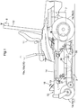
- Fig. 1 is a side view of an electric grass mower (referred to as a "grass mower” hereinafter).
- the grass mower includes: a front wheel unit 1 having a left front wheel 1a and a right front wheel 1b that are of a caster type and can freely rotate; a drive wheel unit 2 that includes a left rear wheel 2a and a right rear wheel 2b; a vehicle body frame 10 that is supported by the front wheel unit 1 and the drive wheel unit 2; a battery 7 that is arranged on the rear portion of the vehicle body frame 10; a driver's seat 11 arranged forward of the battery 7; a rollover protection frame 12 standing upright rearward of the driver's seat 11; and a mower unit 3 that is suspended from the vehicle body frame 10 in a space below the vehicle body frame 10, between the front wheel unit 1 and the driving wheel unit 2, such that the mower unit 3 can be lifted and lowered by a lifting/lowering link mechanism 13.
- a satellite positioning module 8 including an antenna that receives satellite radio waves, is attached to the peak of the rollover protection
- a steering unit 15 is provided on opposite sides of the driver seat 11, including a left steering lever 15a and a right steering lever 15b that pivot about a horizontal pivot axis in a direction that traverses the vehicle body.
- the rotational speed of the left rear wheel 2a can be changed using the left steering lever 15a, and the rotation speed of the right front wheel 1b can be changed using the right steering lever 15b.
- the rotational speeds of the left rear wheel 2a and the right rear wheel 2b can be individually changed, and a sharp turn can be made by setting the rotation directions thereof to be reversed relative to each other.
- the mower unit 3 includes a mower deck 30 and two rotary cutter blades 20.
- the left cutter blade 20 and the right cutter blade 20 are arranged side by side in a direction that traverses the vehicle body.
- the mower deck 30 includes a top wall 31 and side walls 32 that extend downward from the outer peripheral edge of the top wall 31.
- the cutter blades 20 are arranged in the internal space of the mower deck 30, which internal space is defined by the top wall 31 and the side walls 32.
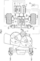
- Fig. 2 shows the power system and the control system of the grass mower.
- a mower motor 4 is attached to the mower deck 30 for supplying motive power to the rotation shafts 21 mounting the respective cutter blades 20 thereon.
- a belt transmission mechanism 22 is employed for transmitting motive power from the mower motor 4 to the rotation shafts 21.
- a left motor 41 is provided for rotating the left rear wheel 2a, and a right motor 42 is provided for rotating the right rear wheel 2b.
- the left motor 41 and the right motor 42 are traveling motors which are driven independent of each other.
- Electric power is supplied from an inverter 70 to the left motor 41, the right motor 42 and the mower motor 4.
- the inverter 70 includes a travel motor inverter 71 that supplies electric power to the left motor 41 and the right motor 42, and a mower motor inverter 72 that supplies electric power to the mower motor 4.
- the inverter 70 is driven based on a control signal from the control unit 5.
- the inverter 70 is connected to the battery 7 serving as the power source.
- the battery 7 is provided with a battery management unit 7A that performs management of charging/discharging of the battery 7, calculation of the SOC, calculation of the battery voltage, calculation of the number of instances of charging/discharging, and the like.
- three (3) work modes with different loads on the battery 7 are set in the control unit 5, so that the driver can select his/her desired one of the modes using a work mode selection tool 81 to perform grass mowing work accordingly.
- the three (3) work modes are an eco-friendly mode, a standard mode and a full-power mode.
- the eco-friendly mode is an energy-saving mode that suppresses power consumption and is intended for long-term work and low noise.
- the standard mode is a mode that is intended for a favorable balance between the grass cutting ability and the power consumption.
- the full-power mode is a mode in which the output is hardly restricted at all, and is intended for demonstration of the maximum grass cutting ability.
- the load on the battery 7 is at its maximum in the full-power mode, the standard mode has the next-highest load, and the eco-friendly mode has the smallest load.
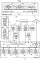
- Fig. 3 shows a control system that is built in the above-described grass mower, and functional units that constitute the work vehicle management system of a management computer 100.
- the management computer 100 is set in a management center KS located away from the work site, and performs a cloud service.
- the functional units built in the management computer 100 are built in a user terminal 200 that can perform data communication.
- the management computer 100 functions as a data processing apparatus that can perform data communication with the control system of the grass mower.
- a control unit 5 which is a core element of the control system of the grass mower, is provided with an input/output processing unit 58 that functions as an input/output interface, and a communication unit 59.
- the inverter 70, a battery management unit 7A, the work mode selection tool 81, a satellite positioning module 8, a notification device 82, a travel state detection sensor group 83, a work state detection sensor group 84, etc. are connected to the input/output processing unit 58.
- the inverter 70 includes a travel motor inverter 71 and a mower motor inverter 72.
- the travel state detection sensor group 83 includes a left steering angle detection sensor 91a, a right steering angle detection sensor 91b, a left motor rotation detection sensor 92a and a right steering angle detection sensor 92b, which are shown in Fig. 2 ; and further includes a first inverter current detector 94a, which is shown in Fig. 3 .
- the work state detection sensor group 84 includes a mower motor rotation detection sensor 93, a second inverter current detector 94b, etc.
- the first inverter current detector 94a detects the current of the travel motor inverter 71
- the second inverter current detector 94b detects the current of the mower motor inverter 72.
- the battery management unit 7A provides the control unit 5 with the battery temperature, the battery voltage, the number of instances of charging/discharging, chronological data of the SOC, the SOC when fully-charged, the calculation of the battery voltage, the calculation of the number of instances of charging/discharging, etc.
- the notification device 82 includes a device for notifying the driver of various types of information, including the battery deterioration information which will be described in detail later.
- a device may include a buzzer, a speaker, an LED (light emitting diode) and a flat panel display.
- the communication unit 59 functions to transmit the data processed by the control unit 5 to the management computer 100, that is built in the management center KS at a remote location, and/or the user terminal 200, and further functions to receive various types of data from the management computer 100.
- the control unit 5 includes a vehicle position calculation unit 51, a travel motor control unit 52, a mower motor control unit 53, a battery work information generation unit 54, a battery information acquisition unit 55 and a notification unit 56.
- the vehicle position calculation unit 51 calculates the vehicle position based on the position information from the satellite positioning module 8 employing GPS and the like.
- the vehicle position calculation unit 51 includes map data, and therefore not only the longitude/latitude data, but also the address of the work site and the like are outputted as the vehicle position. Also, since date-time data is also included in the position information, it is also possible to derive the weather and the like during work, based on the address of the work site and the date-time data by using a web service or the like.
- the travel motor control unit 52 includes a left wheel speed calculation function, a right wheel speed calculation function and a control signal generation function.
- the left wheel speed calculation function calculates the rotation speed (rotation rate) of the left rear wheel 2a, that is, the rotation speed (rotation rate) of the left motor 41 based on the detection signal from the left steering angle detection sensor 91a that detects the operation amount of the left steering lever 15a operated by the driver.
- the right wheel speed calculation function calculates the rotation speed (rotation rate) of the right rear wheel 2b, that is, the rotation speed (rotation rate) of the right motor 42 based on the detection signal from the right steering angle detection sensor 91b that calculates the operation amount of the right steering lever 15b operated by the driver.
- the control signal generation function generates a control signal for supplying the electric power needed to realize the calculated rotation speed of the left motor 41 and the calculated rotation speed of the right motor 42 to the left motor 41 and the right motor 42, respectively; and provides the travel motor inverter 71 with the control signal.
- the travel motor inverter 71 independently supplies electric power to the left motor 41 and to the right motor 42. Accordingly, the rotation speeds of the left rear wheel 2a and the right rear wheel 2b can be made different from each other, and the direction of the grass mower is changed due to the speed difference between the right and left rear wheels.
- the mower motor control unit 53 controls the mower motor inverter 72 to drive the mower motor 4.
- each of the travel motor control unit 52 and the mower motor control unit 53 corrects the control signal to be provided to the inverter 70, according to the work mode selected using the work mode selection tool 81.
- the battery work information generation unit 54 generates battery work information indicating the use state of the battery 7 during work travel of the grass mower.
- the battery work information includes the location of the work site on which the work travel is carried out, the work date and time, and the work load level of the work travel. The location of the work site, and the work date and time are obtained from the vehicle position calculation unit 51.
- the work load level is determined based on the selected work mode and work time.
- the battery work information includes the inverter electric power generated by the inverter 70, the battery information (battery temperature, battery voltage, number of instances of charging/discharging, etc.) obtained from the battery management unit 7A.
- the ID of the battery, the ID of the work vehicle, the ID of the driver, etc. are added to the battery work information.
- the battery information acquisition unit 55 downloads the battery deterioration information generated by the management computer 100 and provides the notification unit 56 with the battery deterioration information. Acquisition of the battery deterioration information by the battery information acquisition unit 55 may be performed automatically during activation of the grass mower, for example, or may be performed manually at any timing in response to an operation instruction performed by the driver.
- the notification unit 56 generates the notification data based on the battery deterioration information and performs notification of the battery deterioration information through the notification device 82.
- the battery information acquisition unit 55 can also perform notification of the content of the battery information obtained from the battery management unit 7A by providing the notification unit 56 with the battery information.
- the management computer 100 which can exchange data with the control unit 5 of the grass mower using a data communication line and the communication unit 104, includes functional units that manage the work travel state of the grass mower, and in particular, the use state of the battery 7.
- the battery work information storage unit 101, a battery deterioration information generation unit 102 and a work vehicle management unit 103 are built in the management computer 100.
- the battery work information storage unit 101 accumulates the battery work information that was generated by the battery work information generation unit 54 of the grass mower and was uploaded, such that the battery work information can be sorted according to the ID of the battery 7, the ID of the grass mower (work vehicle), the ID of the driver and the like, and can be sorted chronologically.
- the work vehicle management unit 103 stores and manages the information related to various work vehicles is to be managed, including the grass mower; and the information may include work content/history data of the work vehicle, such as the work vehicle ID, manager data and work site data.
- the battery deterioration information generation unit 102 extracts, from the work vehicle management unit 103, the management data and other various specification data of the grass mower to be processed; and extracts, from the battery work information storage unit 101, the battery work information of the grass mower that is to be diagnosed.
- the battery deterioration information generation unit 102 chronologically diagnoses the battery work information to generate the battery deterioration information indicating the deterioration trend of the battery 7 unique to the grass mower.
- a machine learning algorithm that receives input of various types of data included in the battery work information and outputs the battery deterioration level, is appropriate as the method for generating the battery deterioration information from the battery work information.
- each piece of data is classified based on the load level on the battery 7; and the battery overuse level is determined through statistical calculation of the classification value of the temperature history data, the classification value of the voltage history data and the classification value of the charging/discharging count data, such as the total value of the classification values, a weighted average value of the classification values or the like.
- the driver of the grass mower may be notified, in a simple method (e.g. a message on an LED display device or other display devices), of whether or not the grass mower has been made with consideration given to the battery.
- the deterioration of the battery 7 is influenced by the state of the work site such as the weather, the work load level of the performed work travel and the like. Accordingly, if the battery overuse level is derived from the battery work information, it is important to keep track of the environment information of the work travel.
- the environment state such as the ground state, the weather and the like of the work site on that day can be derived from the vehicle position during work travel of the work vehicle and the work date and time of the work vehicle, through a web service or the like.
- the work load level of the work travel can be readily estimated based on the work mode that is selected during the work.
- the battery deterioration information generation unit 102 has a function of adding such data indicating the work environment, as attribute information of the battery deterioration information.
- the battery deterioration information generation unit 102 includes processing functions for generating various types of data to be included in the battery deterioration information. Examples thereof are listed below.
- the above-described battery work information storage unit 101, the battery deterioration information generation unit 102 and the work management unit 103 can also be built in a user terminal 200 such as a tablet computer owned by a user.
- the user terminal 200 functions as a data processing apparatus that can perform data communication with the control system of the grass mower, instead of the management computer in the management center KS.
- the user terminal 200 is connected wirelessly or by wire to an onboard LAN of the grass mower and performs functions corresponding to the above-described management computer 100.
- at least one or its portion of the battery work information generation unit 54, the battery information acquisition unit 55 and the notification unit 56 may be built in such a user terminal 200.
- the work vehicle management system according to the present invention can be built in the conventional grass mower, with substantially no modification of the grass mower.
- the battery work information includes temperature history data, SOC history data, voltage history data and charging/discharging instance count data.
- the battery deterioration information generation unit 102 calculates the battery overuse level as the battery deterioration information based on the temperature history data, the SOC history data, the voltage history data and the charging/discharging count data. Furthermore, the battery overuse level is calculated based on the temperature history, the SOC history, the voltage history and the number of instances of charging/discharging, and notification of this battery overuse level is performed.
- a simple example of the battery overuse level is the total value of the values obtained by scoring the temperature history, the SOC history, the voltage history and the number of instances of charging/discharging, using thresholds corresponding respectively thereto. Furthermore, the levels “excellent”, “good”, “acceptable” and “not acceptable” are determined based on the total value, and are ultimately notified through an LED display device or the like.
- the data used as the data indicating battery deterioration may be one of the temperature history data, the SOC history data, the voltage history data and the charging/discharging instance count data, and other data may also be employed.
- calculating the battery overuse level as the battery deterioration information is optional, and the precise deterioration state of the battery can be kept track of as long as the battery overuse level can be checked based on at least one type of the above-described data.
Landscapes
- Engineering & Computer Science (AREA)
- Life Sciences & Earth Sciences (AREA)
- Sustainable Development (AREA)
- Mechanical Engineering (AREA)
- Transportation (AREA)
- Power Engineering (AREA)
- Sustainable Energy (AREA)
- General Chemical & Material Sciences (AREA)
- Electrochemistry (AREA)
- Chemical Kinetics & Catalysis (AREA)
- Chemical & Material Sciences (AREA)
- Manufacturing & Machinery (AREA)
- Physics & Mathematics (AREA)
- Environmental Sciences (AREA)
- General Physics & Mathematics (AREA)
- Microelectronics & Electronic Packaging (AREA)
- Harvester Elements (AREA)
- Charge And Discharge Circuits For Batteries Or The Like (AREA)
- Secondary Cells (AREA)
- Tests Of Electric Status Of Batteries (AREA)
- Electric Propulsion And Braking For Vehicles (AREA)
Abstract
Description
- This application claims priority to Japanese Patent Application No.
2017-223579, filed November 21, 2017 - The present invention relates to a work vehicle that performs work using a battery as a driving source, and a work vehicle management system for managing such a work vehicle. As long as there are no clear limitations, "work" in the following description includes both performing work while causing a vehicle body to travel ("work travel") and performing only work with the vehicle body stopped ("non-traveling work").
- With a work vehicle including an electric motor that rotates using a battery as a driving source, it is important to handle the battery, and in particular, to prevent over-charging and over-discharging and to determine the battery replacement time. An electric grass mower according to
JP 2013-027202A - An electric grass mower according to
JP 2017-158516A US 2017/0263914A1 corresponding thereto) is equipped with multiple battery packs that can be used selectively using a battery switch, and includes a function of controlling switching on and off of the battery switch based on a result of estimating a charge capacity using a charge capacity estimation unit, and based on a result of evaluating battery temperature using a heat evaluation unit. If a battery pack with a charge capacity that is lower than a reference value or a battery pack with a battery temperature that is higher than a reference value is detected, the battery switch connected to that battery pack is switched off. If a backup battery pack is equipped, the battery switch is switched on. Accordingly, switching from a battery pack with a charge capacity that is lower than a reference value to a fully-charged battery pack is performed automatically. - With a work vehicle in which a conventional battery is used as a driving source, charging/discharging control of a battery for the purpose of protecting the battery is performed manually or automatically using the calculated SOC. However, information for checking whether or not driving that is appropriate for the battery is being performed, or in other words, whether or not the battery deterioration trend is appropriate, has not been collected for each work vehicle or driver, despite the fact that the lifespan, discharge time, and the like of the battery are influenced by the way the driver drives, the state of the work site, the weather, and the like. For this reason, a manager of the work vehicle such as the driver cannot find out whether or not the battery deterioration trend is appropriate, and for this reason, a problem may occur in which work and/or traveling that shorten the lifespan of the battery are repeated.
- In view of the foregoing circumstance, there has been desire for a work vehicle management system and a work machine according to which it is possible to provide information that enables determination of whether or not a deterioration trend of a battery equipped in a work vehicle is appropriate. In view of this, first, the following work vehicle management system is proposed.
- A work vehicle management system for managing a work vehicle configured to perform work using a battery as a driving source, comprising:
- a battery work information generation unit configured to generate battery work information that indicates a use state of the battery during the work of the work vehicle;
- a battery deterioration information generation unit configured to chronologically diagnose the battery work information to generate battery deterioration information that indicates a deterioration trend of the battery that is unique to the work vehicle; and
- a notification unit configured to perform notification of the battery deterioration information to a manager of the work vehicle.
- According to this configuration, the use state of the battery of a specific work vehicle is included in the battery work information, and therefore by collecting the battery work information over time and evaluating the collected battery work information using a statistical method, for example, it is possible to diagnose the deterioration trend of a battery that is unique for each work vehicle. For example, it is possible to diagnose the deterioration trend of the battery of the specific work vehicle by comparing a reference use state, which is the average value of the use states of the batteries of many work vehicles, and the use state of the battery of the specific work vehicle. The battery deterioration information obtained in this manner is notified to a manager, such as the driver of the work vehicle being diagnosed, and therefore the manager can objectively check the deterioration trend of the battery.
- In one preferable embodiment, the battery work information generation unit and the notification unit are included in a control system of the work vehicle, and the battery deterioration information generation unit is included in a data processing apparatus that is configured to perform data communication with the control system.
- With this configuration, if the data processing apparatus is built in a computer that performs a cloud service, the battery deterioration information of each work vehicle can be generated by storing the battery work information of many work vehicles and statistically processing these pieces of battery work information. The data processing apparatus provides the generated battery deterioration information based on a request from the control system of the work vehicle. Notification of the received battery deterioration information is performed by the notification unit through a speaker or a display, and thereby the manager (driver) of the work vehicle can keep track of the use state of the manager's work vehicle, and in particular, the use state (deterioration state) of the battery.
- Preferably, the data processing apparatus is provided in a management center away from a work site or in a user terminal owned by a user of a work vehicle, and is connected so as to be able to communicate with an onboard LAN (local area network) of a work vehicle wirelessly or by wire.
- In one preferable embodiment, the battery work information includes at least one of temperature history data, SOC (state of charge) history data, voltage history data and charging/discharging instance count data, and
the battery deterioration information generation unit calculates a battery overuse level as the battery deterioration information based on at least one of the temperature history data, the SOC history data, the voltage history data and the charging/discharging instance count data. - According to this configuration, the temperature history data is data that can indicate the frequency of the temperature that causes the battery to deteriorate. The SOC history data is data that can indicate the frequency of repeating the low remaining amount, the voltage history data is data that can indicate the frequency of voltage fluctuation that causes the battery to deteriorate, and thus it is possible to keep track of the period of being at a voltage at which the battery deteriorates rapidly. The charging/discharging instance count data is data indicating the number of instances of charging and discharging at a unit date and time. A battery, and in particular, a lithium-type battery, progressively deteriorates depending on conditions such as battery temperature behavior, repetition of battery exhaustion, the deterioration behavior of the battery voltage, and the number of instances of charging/discharging.
- With this configuration, the battery overuse level is calculated based on at least one of the temperature history, the SOC history, the voltage history, and the number of instances of charging/discharging, and therefore by performing notification of this battery overuse level, the manager of the work vehicle can keep track of the precise deterioration state of the battery equipped in the work vehicle. In particular, as a simple specific example, it is proposed that the above-described temperature history, SOC history, voltage history, and number of instances of charging/discharging are scored, and the levels "great", "good", "acceptable", and "not acceptable" are determined based on the total value. During the scoring, it is preferable that points are allocated by setting one or more thresholds and classifying each piece of data. With this kind of battery deterioration information, it is also possible to perform notification through a simple LED display.
- However, calculation (scoring) is optional, and the precise deterioration state of the battery can be kept track of as long as the battery overuse level can be checked based on at least one of the above-described types of data.
- In a preferable embodiment, the battery work information includes the battery work information includes a location of a work site where the work is carried out, a work date and time, and a work load level of the work, and an environment state of the work site and an appropriate work load level are added as attribute information of the battery deterioration information. This configuration is advantageous in the following respects.
- The environmental state such as the ground state of the work site and the weather on that day is derived through a web service or the like based on the position of the work vehicle during work, which can be easily acquired by the work vehicle by equipping a satellite positioning module such as a GPS (global positioning system), and based on the work date and time.
- Also, if the work vehicle is provided with selectable work modes that are divided according to work load, the load level of the work can be determined based on the selected work mode.
- Also, as long as the work vehicle includes a function of detecting the load of the electric motor or a function of detecting the work amount, the load level of the work can be determined based on the detected motor load or work amount.
- By employing these kinds of configurations, the manager of the work vehicle can, based on the attribute information of the battery deterioration information, keep track of the work environment in which the work that resulted in the content indicated by the battery deterioration information was carried out. Accordingly, it is possible to plan future improved use of the work vehicle that performs work using the battery as the driving source.
- Preferably, the appropriate work load level is a level that is recommended for appropriate use of the battery, and is derived from data obtained from at least one of the following functions:
- (1) a function of performing estimation of a work trend and estimation of the battery deterioration trend based on a chronological evaluation of a work date and time and a work mode, and using the estimation result as the battery deterioration information;
- (2) a function of correcting original data relating to battery deterioration included in the battery deterioration information according to a work travel location;
- (3) a function of calculating motor energy consumption for each driver or for each work vehicle;
- (4) a function of statistically analyzing a work time and a work amount for each driver or for each work vehicle;
- (5) a function of, if the battery is constituted by a plurality of battery packs, calculating an overuse level for each battery pack using a battery pack ID;
- (6) a function of calculating a battery lifespan from a battery remaining amount when fully-charged;
- (7) a function of calculating a deterioration correction value during battery storage from the battery remaining amount when the vehicle is stopped; and
- (8) a function of statistically analyzing an abnormality of the battery such as a battery temperature abnormality.
- The present invention is applied also to a work vehicle having a battery serving as a driving source for work and a work vehicle management system having any of the above-described configurations.
- A high-performance tablet computer capable of wireless data communication is included in some recent work vehicles. By including a battery deterioration information generation unit as an application program in this tablet computer, a work vehicle management system of the present invention, which includes the above-described preferable embodiments can be built in the interior of the work vehicle.
- Other characteristics and advantages to be demonstrated hereinafter will become apparent upon reading the following description.
-
-
Fig. 1 is a side view of a mid-mount riding electric grass mower equipped with a mower unit, according to an embodiment. -
Fig. 2 is a schematic diagram showing a power system and a control system of the electric grass mower. -
Fig. 3 is a functional block diagram of a control system. - In the embodiment described hereinafter, the work vehicle is an electric grass mower. Note that in the present specification, unless otherwise stated in particular, "front" means forward in the front-rear direction (traveling direction) of the vehicle body, and "rear" means rearward in the front-rear direction (traveling direction) of the vehicle body. Also, the right-left direction or lateral direction means the direction that traverses the machine body (machine body width direction), which is orthogonal to the vehicle body front-rear direction. "Up" and "down" are positional relationships in the vertical direction (perpendicular direction) of the vehicle body and indicate relationships with respect to the above-ground height.
-
Fig. 1 is a side view of an electric grass mower (referred to as a "grass mower" hereinafter). The grass mower includes: afront wheel unit 1 having a leftfront wheel 1a and a rightfront wheel 1b that are of a caster type and can freely rotate; adrive wheel unit 2 that includes a leftrear wheel 2a and a rightrear wheel 2b; avehicle body frame 10 that is supported by thefront wheel unit 1 and thedrive wheel unit 2; abattery 7 that is arranged on the rear portion of thevehicle body frame 10; a driver'sseat 11 arranged forward of thebattery 7; arollover protection frame 12 standing upright rearward of the driver'sseat 11; and amower unit 3 that is suspended from thevehicle body frame 10 in a space below thevehicle body frame 10, between thefront wheel unit 1 and thedriving wheel unit 2, such that themower unit 3 can be lifted and lowered by a lifting/loweringlink mechanism 13. Asatellite positioning module 8, including an antenna that receives satellite radio waves, is attached to the peak of therollover protection frame 12. - A
floor plate 14, on which the driver's feet can be placed, is provided forward of the driver'sseat 11; and abrake pedal 16 protrudes through thefloor plate 14. Asteering unit 15 is provided on opposite sides of thedriver seat 11, including aleft steering lever 15a and aright steering lever 15b that pivot about a horizontal pivot axis in a direction that traverses the vehicle body. The rotational speed of the leftrear wheel 2a can be changed using theleft steering lever 15a, and the rotation speed of the rightfront wheel 1b can be changed using theright steering lever 15b. The rotational speeds of the leftrear wheel 2a and the rightrear wheel 2b can be individually changed, and a sharp turn can be made by setting the rotation directions thereof to be reversed relative to each other. - The
mower unit 3 includes amower deck 30 and tworotary cutter blades 20. Theleft cutter blade 20 and theright cutter blade 20 are arranged side by side in a direction that traverses the vehicle body. Themower deck 30 includes atop wall 31 andside walls 32 that extend downward from the outer peripheral edge of thetop wall 31. Thecutter blades 20 are arranged in the internal space of themower deck 30, which internal space is defined by thetop wall 31 and theside walls 32. -
Fig. 2 shows the power system and the control system of the grass mower. A mower motor 4 is attached to themower deck 30 for supplying motive power to therotation shafts 21 mounting therespective cutter blades 20 thereon. Abelt transmission mechanism 22 is employed for transmitting motive power from the mower motor 4 to therotation shafts 21. Aleft motor 41 is provided for rotating the leftrear wheel 2a, and aright motor 42 is provided for rotating the rightrear wheel 2b. In this embodiment, theleft motor 41 and theright motor 42 are traveling motors which are driven independent of each other. - Electric power is supplied from an
inverter 70 to theleft motor 41, theright motor 42 and the mower motor 4. Theinverter 70 includes atravel motor inverter 71 that supplies electric power to theleft motor 41 and theright motor 42, and amower motor inverter 72 that supplies electric power to the mower motor 4. Theinverter 70 is driven based on a control signal from thecontrol unit 5. Theinverter 70 is connected to thebattery 7 serving as the power source. Thebattery 7 is provided with abattery management unit 7A that performs management of charging/discharging of thebattery 7, calculation of the SOC, calculation of the battery voltage, calculation of the number of instances of charging/discharging, and the like. - In this embodiment, three (3) work modes with different loads on the
battery 7 are set in thecontrol unit 5, so that the driver can select his/her desired one of the modes using a workmode selection tool 81 to perform grass mowing work accordingly. The three (3) work modes are an eco-friendly mode, a standard mode and a full-power mode. The eco-friendly mode is an energy-saving mode that suppresses power consumption and is intended for long-term work and low noise. The standard mode is a mode that is intended for a favorable balance between the grass cutting ability and the power consumption. The full-power mode is a mode in which the output is hardly restricted at all, and is intended for demonstration of the maximum grass cutting ability. Of course, the load on thebattery 7 is at its maximum in the full-power mode, the standard mode has the next-highest load, and the eco-friendly mode has the smallest load. -
Fig. 3 shows a control system that is built in the above-described grass mower, and functional units that constitute the work vehicle management system of amanagement computer 100. Themanagement computer 100 is set in a management center KS located away from the work site, and performs a cloud service. Note that in the case of a small-scale system, the functional units built in themanagement computer 100 are built in auser terminal 200 that can perform data communication. In this embodiment, themanagement computer 100 functions as a data processing apparatus that can perform data communication with the control system of the grass mower. - A
control unit 5, which is a core element of the control system of the grass mower, is provided with an input/output processing unit 58 that functions as an input/output interface, and acommunication unit 59. Theinverter 70, abattery management unit 7A, the workmode selection tool 81, asatellite positioning module 8, anotification device 82, a travel statedetection sensor group 83, a work statedetection sensor group 84, etc. are connected to the input/output processing unit 58. Theinverter 70 includes atravel motor inverter 71 and amower motor inverter 72. The travel statedetection sensor group 83 includes a left steeringangle detection sensor 91a, a right steeringangle detection sensor 91b, a left motorrotation detection sensor 92a and a right steeringangle detection sensor 92b, which are shown inFig. 2 ; and further includes a first invertercurrent detector 94a, which is shown inFig. 3 . The work statedetection sensor group 84 includes a mower motorrotation detection sensor 93, a second invertercurrent detector 94b, etc. The first invertercurrent detector 94a detects the current of thetravel motor inverter 71, and the second invertercurrent detector 94b detects the current of themower motor inverter 72. - As the battery information, the
battery management unit 7A provides thecontrol unit 5 with the battery temperature, the battery voltage, the number of instances of charging/discharging, chronological data of the SOC, the SOC when fully-charged, the calculation of the battery voltage, the calculation of the number of instances of charging/discharging, etc. - The
notification device 82 includes a device for notifying the driver of various types of information, including the battery deterioration information which will be described in detail later. Such a device may include a buzzer, a speaker, an LED (light emitting diode) and a flat panel display. Thecommunication unit 59 functions to transmit the data processed by thecontrol unit 5 to themanagement computer 100, that is built in the management center KS at a remote location, and/or theuser terminal 200, and further functions to receive various types of data from themanagement computer 100. - The
control unit 5 includes a vehicleposition calculation unit 51, a travelmotor control unit 52, a mowermotor control unit 53, a battery workinformation generation unit 54, a batteryinformation acquisition unit 55 and anotification unit 56. - The vehicle
position calculation unit 51 calculates the vehicle position based on the position information from thesatellite positioning module 8 employing GPS and the like. In this embodiment, the vehicleposition calculation unit 51 includes map data, and therefore not only the longitude/latitude data, but also the address of the work site and the like are outputted as the vehicle position. Also, since date-time data is also included in the position information, it is also possible to derive the weather and the like during work, based on the address of the work site and the date-time data by using a web service or the like. - The travel
motor control unit 52 includes a left wheel speed calculation function, a right wheel speed calculation function and a control signal generation function. The left wheel speed calculation function calculates the rotation speed (rotation rate) of the leftrear wheel 2a, that is, the rotation speed (rotation rate) of theleft motor 41 based on the detection signal from the left steeringangle detection sensor 91a that detects the operation amount of theleft steering lever 15a operated by the driver. The right wheel speed calculation function calculates the rotation speed (rotation rate) of the rightrear wheel 2b, that is, the rotation speed (rotation rate) of theright motor 42 based on the detection signal from the right steeringangle detection sensor 91b that calculates the operation amount of theright steering lever 15b operated by the driver. The control signal generation function generates a control signal for supplying the electric power needed to realize the calculated rotation speed of theleft motor 41 and the calculated rotation speed of theright motor 42 to theleft motor 41 and theright motor 42, respectively; and provides thetravel motor inverter 71 with the control signal. Thetravel motor inverter 71 independently supplies electric power to theleft motor 41 and to theright motor 42. Accordingly, the rotation speeds of the leftrear wheel 2a and the rightrear wheel 2b can be made different from each other, and the direction of the grass mower is changed due to the speed difference between the right and left rear wheels. - The mower
motor control unit 53 controls themower motor inverter 72 to drive the mower motor 4. In this embodiment, each of the travelmotor control unit 52 and the mowermotor control unit 53 corrects the control signal to be provided to theinverter 70, according to the work mode selected using the workmode selection tool 81. - The battery work
information generation unit 54 generates battery work information indicating the use state of thebattery 7 during work travel of the grass mower. The battery work information includes the location of the work site on which the work travel is carried out, the work date and time, and the work load level of the work travel. The location of the work site, and the work date and time are obtained from the vehicleposition calculation unit 51. The work load level is determined based on the selected work mode and work time. In order to express the detailed work load level, the battery work information includes the inverter electric power generated by theinverter 70, the battery information (battery temperature, battery voltage, number of instances of charging/discharging, etc.) obtained from thebattery management unit 7A. The ID of the battery, the ID of the work vehicle, the ID of the driver, etc. are added to the battery work information. - In the present embodiment, the battery
information acquisition unit 55 downloads the battery deterioration information generated by themanagement computer 100 and provides thenotification unit 56 with the battery deterioration information. Acquisition of the battery deterioration information by the batteryinformation acquisition unit 55 may be performed automatically during activation of the grass mower, for example, or may be performed manually at any timing in response to an operation instruction performed by the driver. Thenotification unit 56 generates the notification data based on the battery deterioration information and performs notification of the battery deterioration information through thenotification device 82. Note that the batteryinformation acquisition unit 55 can also perform notification of the content of the battery information obtained from thebattery management unit 7A by providing thenotification unit 56 with the battery information. - In this embodiment, the
management computer 100, which can exchange data with thecontrol unit 5 of the grass mower using a data communication line and thecommunication unit 104, includes functional units that manage the work travel state of the grass mower, and in particular, the use state of thebattery 7. In more specific, the battery workinformation storage unit 101, a battery deteriorationinformation generation unit 102 and a workvehicle management unit 103 are built in themanagement computer 100. - The battery work
information storage unit 101 accumulates the battery work information that was generated by the battery workinformation generation unit 54 of the grass mower and was uploaded, such that the battery work information can be sorted according to the ID of thebattery 7, the ID of the grass mower (work vehicle), the ID of the driver and the like, and can be sorted chronologically. The workvehicle management unit 103 stores and manages the information related to various work vehicles is to be managed, including the grass mower; and the information may include work content/history data of the work vehicle, such as the work vehicle ID, manager data and work site data. - The battery deterioration
information generation unit 102 extracts, from the workvehicle management unit 103, the management data and other various specification data of the grass mower to be processed; and extracts, from the battery workinformation storage unit 101, the battery work information of the grass mower that is to be diagnosed. The battery deteriorationinformation generation unit 102 chronologically diagnoses the battery work information to generate the battery deterioration information indicating the deterioration trend of thebattery 7 unique to the grass mower. A machine learning algorithm, that receives input of various types of data included in the battery work information and outputs the battery deterioration level, is appropriate as the method for generating the battery deterioration information from the battery work information. - In order to generate the battery deterioration information from the battery work information in a simple manner, it is preferable to derive the battery overuse level based on the temperature history data, the voltage history data and the charging/discharging instance count data, taken from the battery work information. In the algorithm for deriving the battery overuse level, each piece of data is classified based on the load level on the
battery 7; and the battery overuse level is determined through statistical calculation of the classification value of the temperature history data, the classification value of the voltage history data and the classification value of the charging/discharging count data, such as the total value of the classification values, a weighted average value of the classification values or the like. If the battery overuse levels are "excellent", "good", "acceptable" and "not acceptable", for example, the driver of the grass mower may be notified, in a simple method (e.g. a message on an LED display device or other display devices), of whether or not the grass mower has been made with consideration given to the battery. - The deterioration of the
battery 7 is influenced by the state of the work site such as the weather, the work load level of the performed work travel and the like. Accordingly, if the battery overuse level is derived from the battery work information, it is important to keep track of the environment information of the work travel. The environment state such as the ground state, the weather and the like of the work site on that day can be derived from the vehicle position during work travel of the work vehicle and the work date and time of the work vehicle, through a web service or the like. Also, the work load level of the work travel can be readily estimated based on the work mode that is selected during the work. The battery deteriorationinformation generation unit 102 has a function of adding such data indicating the work environment, as attribute information of the battery deterioration information. - The battery deterioration
information generation unit 102 includes processing functions for generating various types of data to be included in the battery deterioration information. Examples thereof are listed below. - (1) A function of performing estimation of the work trend and estimation of the battery deterioration trend based on a chronological evaluation of the work date and time and the work mode, and using the estimation result as the battery deterioration information.
- (2) An auxiliary function of correcting the original data relating to battery deterioration included in the battery deterioration information according to the work travel location.
- (3) A function of calculating motor consumption energy for each driver or for each grass mower.
- (4) A function of statistically analyzing the work time and the work amount for each driver or for each grass mower.
- (5) A function of, if the
battery 7 is constituted by multiple battery packs, calculating the overuse level for each battery pack using the battery pack ID. - (6) A function of calculating the battery lifespan from the SOC when fully-charged.
- (7) A function of calculating a deterioration correction value during battery storage from the SOC when the vehicle is stopped.
- (8) A function of statistically analyzing a battery abnormality such as a battery temperature abnormality.
- (9) A function of deriving an appropriate work load level that is to be recommended for appropriate use of the
battery 7, from data obtained by the above-described functions. - Note that the above-described battery work
information storage unit 101, the battery deteriorationinformation generation unit 102 and thework management unit 103 can also be built in auser terminal 200 such as a tablet computer owned by a user. In this case, with the configuration shown inFig. 3 , theuser terminal 200 functions as a data processing apparatus that can perform data communication with the control system of the grass mower, instead of the management computer in the management center KS. Theuser terminal 200 is connected wirelessly or by wire to an onboard LAN of the grass mower and performs functions corresponding to the above-describedmanagement computer 100. Also, at least one or its portion of the battery workinformation generation unit 54, the batteryinformation acquisition unit 55 and thenotification unit 56 may be built in such auser terminal 200. Whereby, the work vehicle management system according to the present invention can be built in the conventional grass mower, with substantially no modification of the grass mower. - Also, in the above-described embodiment, the battery work information includes temperature history data, SOC history data, voltage history data and charging/discharging instance count data. The battery deterioration
information generation unit 102 calculates the battery overuse level as the battery deterioration information based on the temperature history data, the SOC history data, the voltage history data and the charging/discharging count data. Furthermore, the battery overuse level is calculated based on the temperature history, the SOC history, the voltage history and the number of instances of charging/discharging, and notification of this battery overuse level is performed. - A simple example of the battery overuse level is the total value of the values obtained by scoring the temperature history, the SOC history, the voltage history and the number of instances of charging/discharging, using thresholds corresponding respectively thereto. Furthermore, the levels "excellent", "good", "acceptable" and "not acceptable" are determined based on the total value, and are ultimately notified through an LED display device or the like. Of course, the data used as the data indicating battery deterioration may be one of the temperature history data, the SOC history data, the voltage history data and the charging/discharging instance count data, and other data may also be employed.
- However, calculating the battery overuse level as the battery deterioration information is optional, and the precise deterioration state of the battery can be kept track of as long as the battery overuse level can be checked based on at least one type of the above-described data.
- The configuration disclosed in the above-described embodiment (including the other embodiments described below) can be applied in combination with a configuration disclosed in another embodiment as long as there is no discrepancy. The embodiments disclosed in the present specification are exemplary, and the embodiments of the present invention are not limited to this and can be modified as appropriate without departing from the object of the invention.
-
- (1) The above-described battery work
information storage unit 101, battery deteriorationinformation generation unit 102 and workvehicle management unit 103 may be provided in the onboard LAN of the grass mower. - (2) In the above-described embodiment, a grass mower was given as a work vehicle, but the present invention can also be applied to an agricultural work machine such as a combine, a tractor, a rice transplanter and a tiller, and a work machine for another field (e.g., a construction machine such as a backhoe). That is, the work vehicle of the present invention encompasses both grass mowers and agricultural work machines that often perform work while causing the vehicle body to travel ("work travel") and construction machines that often only perform work while the vehicle body is stopped ("non-traveling work").
Claims (8)
- A work vehicle management system for managing a work vehicle configured to perform work using a battery (7) as a driving source, comprising:a battery work information generation unit (54) configured to generate battery work information that indicates a use state of the battery during the work of the work vehicle;a battery deterioration information generation unit (102) configured to chronologically diagnose the battery work information to generate battery deterioration information that indicates a deterioration trend of the battery that is unique to the work vehicle; anda notification unit (56) configured to perform notification of the battery deterioration information to a manager of the work vehicle.
- The work vehicle management system according to claim 1, wherein
the battery work information generation unit (54) and the notification unit (56) are included in a control system (5) of the work vehicle, and
the battery deterioration information generation unit (102) is included in a data processing apparatus (100) that is configured to perform data communication with the control system (5). - The work vehicle management system according to claim 2, wherein
the data processing apparatus (100) is provided in a management center away from a work site or in a user terminal owned by a user of a work vehicle, and is connected to and communicates with an onboard LAN (local area network) of a work vehicle wirelessly or by wire. - The work vehicle management system according to any one of claims 1-3, wherein
the battery work information includes at least one of temperature history data, SOC (state of charge) history data, voltage history data and charging/discharging instance count data, and
the battery deterioration information generation unit (102) calculates a battery overuse level as the battery deterioration information based on at least one of the temperature history data, the SOC history data, the voltage history data and the charging/discharging instance count data. - The work vehicle management system according to any one of claims 1-3, wherein
the battery work information includes at least one of temperature history data, SOC (state of charge) history data, voltage history data and charging/discharging instance count data, and
the battery deterioration information generation unit (102) checks a battery overuse level based on at least one of the temperature history data, the SOC history data, the voltage history data and the charging/discharging instance count data. - The work vehicle management system according to any one of claims 1-5, wherein
the battery work information includes a location of a work site where the work is carried out, a work date and time, and a work load level of the work, and
an environment state of the work site and an appropriate work load level are added as attribute information of the battery deterioration information. - The work vehicle management system according to claim 6, wherein
the appropriate work load level is a level that is recommended for appropriate use of the battery (7), and is derived from data obtained from at least one of the following functions:(1) a function of performing estimation of a work trend and estimation of the battery deterioration trend based on a chronological evaluation of a work date and time and a work mode, and using the estimation result as the battery deterioration information;(2) a function of correcting original data relating to battery deterioration included in the battery deterioration information according to a work travel location;(3) a function of calculating motor energy consumption for each driver or for each work vehicle;(4) a function of statistically analyzing a work time and a work amount for each driver or for each work vehicle;(5) a function of, if the battery is constituted by a plurality of battery packs, calculating an overuse level for each battery pack using a battery pack ID;(6) a function of calculating a battery lifespan from a battery remaining amount when fully-charged;(7) a function of calculating a deterioration correction value during battery storage from the battery remaining amount when the vehicle is stopped; and(8) a function of statistically analyzing an abnormality of the battery such as a battery temperature abnormality. - A work vehicle comprising:a battery (7) serving as a driving source for work of the work vehicle;a battery work information generation unit (54) configured to generate battery work information indicating a use state of the battery during the work;a battery deterioration information generation unit (102) configured to chronologically diagnose the battery work information to generate battery deterioration information that indicates a deterioration trend of the battery that is unique to the work vehicle; anda notification unit (56) configured to perform notification of the battery deterioration information.
Applications Claiming Priority (1)
| Application Number | Priority Date | Filing Date | Title |
|---|---|---|---|
| JP2017223579A JP6811698B2 (en) | 2017-11-21 | 2017-11-21 | Work vehicle and work vehicle management system |
Publications (2)
| Publication Number | Publication Date |
|---|---|
| EP3486109A1 true EP3486109A1 (en) | 2019-05-22 |
| EP3486109B1 EP3486109B1 (en) | 2021-09-08 |
Family
ID=62620735
Family Applications (1)
| Application Number | Title | Priority Date | Filing Date |
|---|---|---|---|
| EP18177238.5A Active EP3486109B1 (en) | 2017-11-21 | 2018-06-12 | Work vehicle and work vehicle management system |
Country Status (3)
| Country | Link |
|---|---|
| US (1) | US11145144B2 (en) |
| EP (1) | EP3486109B1 (en) |
| JP (1) | JP6811698B2 (en) |
Cited By (2)
| Publication number | Priority date | Publication date | Assignee | Title |
|---|---|---|---|---|
| EP4464145A1 (en) * | 2023-05-19 | 2024-11-20 | Iseki & Co., Ltd. | Grass cutter |
| US12150405B2 (en) | 2019-01-11 | 2024-11-26 | Nanjing Chervon Industry Co., Ltd. | Motor housing for a riding lawn mower |
Families Citing this family (19)
| Publication number | Priority date | Publication date | Assignee | Title |
|---|---|---|---|---|
| JP7013864B2 (en) * | 2017-12-28 | 2022-02-01 | トヨタ自動車株式会社 | automobile |
| WO2020090341A1 (en) * | 2018-10-31 | 2020-05-07 | パナソニックIpマネジメント株式会社 | Information processing system, control device, and vehicle power supply system |
| JP7482420B2 (en) * | 2019-11-29 | 2024-05-14 | パナソニックIpマネジメント株式会社 | Vehicle management device and vehicle management program |
| KR20220144379A (en) | 2020-03-02 | 2022-10-26 | 클라크 이큅먼트 컴파니 | power supply power machine |
| DE102020206465A1 (en) | 2020-05-25 | 2021-11-25 | Zf Friedrichshafen Ag | Method for operating an electrically driven work machine, an electric drive train for a work machine and a work machine |
| CN114084043B (en) * | 2020-10-16 | 2024-03-08 | 格力博(江苏)股份有限公司 | Battery management system, battery management method and electric vehicle |
| US12485981B2 (en) | 2021-03-24 | 2025-12-02 | Polaris Industries Inc. | Electric recreational vehicle |
| CN113771676B (en) * | 2021-07-26 | 2023-06-02 | 深圳市兆兴博拓科技股份有限公司 | Intelligent reminder method, device, equipment and storage medium for new energy charging device |
| CA3220521A1 (en) | 2021-09-02 | 2023-03-09 | Brent DURKIN | Lift arm arrangements for power machines |
| CN115868303A (en) | 2021-09-29 | 2023-03-31 | 创科无线普通合伙 | Robotic garden tool system and method for robotic garden tool |
| WO2023053352A1 (en) * | 2021-09-30 | 2023-04-06 | 本田技研工業株式会社 | Electric device |
| DE102021212135A1 (en) | 2021-10-27 | 2023-04-27 | Zf Friedrichshafen Ag | Method for distributing power from an electric drive train of a working machine, control device, computer program product and working machine |
| JP7652141B2 (en) * | 2022-06-29 | 2025-03-27 | トヨタ自動車株式会社 | Information processing device, information processing method, and program |
| JP7796609B2 (en) * | 2022-08-03 | 2026-01-09 | 株式会社クボタ | electric work vehicle |
| JP2024096587A (en) * | 2023-01-04 | 2024-07-17 | 株式会社クボタ | Work Machine |
| WO2024252547A1 (en) * | 2023-06-07 | 2024-12-12 | ヤマハ発動機株式会社 | Robot management device, robot management method, robot management program, and recording medium |
| CN116432985B (en) * | 2023-06-09 | 2023-09-22 | 田凯文 | Intelligent community information processing method and system based on Internet of things |
| US12594828B2 (en) * | 2023-10-30 | 2026-04-07 | Kubota Corporation | Electric work vehicle |
| US12552285B2 (en) | 2023-12-22 | 2026-02-17 | Caterpillar Inc. | System and method of exiting a low power mode for a battery electric machine |
Citations (7)
| Publication number | Priority date | Publication date | Assignee | Title |
|---|---|---|---|---|
| US20090027056A1 (en) * | 2007-07-23 | 2009-01-29 | Yung-Sheng Huang | Battery performance monitor |
| US20110258838A1 (en) * | 2010-04-22 | 2011-10-27 | Mccabe Paul P | Method of allocating batteries for use on specific industrial vehicles in a fleet |
| JP2013027202A (en) | 2011-07-22 | 2013-02-04 | Yanmar Co Ltd | Electric riding mower |
| EP2639096A1 (en) * | 2010-11-10 | 2013-09-18 | Nissan Motor Co., Ltd | Diagnosis apparatus for vehicle battery |
| EP2657062A1 (en) * | 2012-04-25 | 2013-10-30 | Hitachi Automotive Systems, Ltd. | Apparatus and method for controlling power level management of an electric power source of an electrically driven vehicle |
| US20170225584A1 (en) * | 2016-02-04 | 2017-08-10 | Johnson Controls Technology Company | Systems and methods for state of charge and capacity estimation of a rechargeable battery |
| US20170263914A1 (en) | 2016-03-11 | 2017-09-14 | Kubota Corporation | Electric Work Vehicle |
Family Cites Families (3)
| Publication number | Priority date | Publication date | Assignee | Title |
|---|---|---|---|---|
| JP4650532B2 (en) * | 2008-07-11 | 2011-03-16 | トヨタ自動車株式会社 | Storage device deterioration determination device and storage device deterioration determination method |
| JP5413087B2 (en) * | 2009-09-25 | 2014-02-12 | トヨタ自動車株式会社 | Information management system and information management method |
| US9251627B2 (en) * | 2013-03-05 | 2016-02-02 | Sears Brands, L.L.C. | Removable dashboard instrument system |
-
2017
- 2017-11-21 JP JP2017223579A patent/JP6811698B2/en active Active
-
2018
- 2018-06-08 US US16/003,566 patent/US11145144B2/en active Active
- 2018-06-12 EP EP18177238.5A patent/EP3486109B1/en active Active
Patent Citations (8)
| Publication number | Priority date | Publication date | Assignee | Title |
|---|---|---|---|---|
| US20090027056A1 (en) * | 2007-07-23 | 2009-01-29 | Yung-Sheng Huang | Battery performance monitor |
| US20110258838A1 (en) * | 2010-04-22 | 2011-10-27 | Mccabe Paul P | Method of allocating batteries for use on specific industrial vehicles in a fleet |
| EP2639096A1 (en) * | 2010-11-10 | 2013-09-18 | Nissan Motor Co., Ltd | Diagnosis apparatus for vehicle battery |
| JP2013027202A (en) | 2011-07-22 | 2013-02-04 | Yanmar Co Ltd | Electric riding mower |
| EP2657062A1 (en) * | 2012-04-25 | 2013-10-30 | Hitachi Automotive Systems, Ltd. | Apparatus and method for controlling power level management of an electric power source of an electrically driven vehicle |
| US20170225584A1 (en) * | 2016-02-04 | 2017-08-10 | Johnson Controls Technology Company | Systems and methods for state of charge and capacity estimation of a rechargeable battery |
| US20170263914A1 (en) | 2016-03-11 | 2017-09-14 | Kubota Corporation | Electric Work Vehicle |
| JP2017158516A (en) | 2016-03-11 | 2017-09-14 | 株式会社クボタ | Electric work vehicle |
Cited By (4)
| Publication number | Priority date | Publication date | Assignee | Title |
|---|---|---|---|---|
| US12150405B2 (en) | 2019-01-11 | 2024-11-26 | Nanjing Chervon Industry Co., Ltd. | Motor housing for a riding lawn mower |
| US12201059B2 (en) * | 2019-01-11 | 2025-01-21 | Nanjing Chervon Industry Co., Ltd. | Power capacity indicator for a riding lawn mower |
| US12302785B2 (en) | 2019-01-11 | 2025-05-20 | Nanjing Chervon Industry Co., Ltd. | Riding lawn mower with a USB interface |
| EP4464145A1 (en) * | 2023-05-19 | 2024-11-20 | Iseki & Co., Ltd. | Grass cutter |
Also Published As
| Publication number | Publication date |
|---|---|
| US11145144B2 (en) | 2021-10-12 |
| JP6811698B2 (en) | 2021-01-13 |
| US20190156595A1 (en) | 2019-05-23 |
| JP2019097272A (en) | 2019-06-20 |
| EP3486109B1 (en) | 2021-09-08 |
Similar Documents
| Publication | Publication Date | Title |
|---|---|---|
| EP3486109B1 (en) | Work vehicle and work vehicle management system | |
| US11690315B2 (en) | Systems and devices for lawn care | |
| US20250295062A1 (en) | Electric mower | |
| US12145674B2 (en) | Electric outdoor ride-on power equipment | |
| US12500440B2 (en) | Vehicle for transporting and charging outdoor power equipment | |
| CN115280804B (en) | Device management via mesh network | |
| EP2731560B1 (en) | Battery powered lawn care vehicle with efficient drive controller | |
| EP2731413B1 (en) | Battery powered lawn care vehicle with drive efficiency indicator | |
| AU2011200903B2 (en) | Method of allocating batteries for use on specific industrial vehicles in a fleet | |
| US20250206155A1 (en) | System and method for controlling a fleet of fuel cell vehicles | |
| JP2020022296A (en) | Battery connector assembly and battery device | |
| US12479329B2 (en) | Systems and methods for identifying modifications to terrain characteristics of a worksite for battery performance | |
| US10518593B2 (en) | Tire management system and method | |
| EP4339007A1 (en) | Battery management method, storage controller, movable body, and server | |
| US12630039B2 (en) | Battery management method, storage controller, and server | |
| US20260056255A1 (en) | Fault detection and protection for collection systems of power machines | |
| US20240088457A1 (en) | Battery management method, storage medium, storage controller, and movable body | |
| JP2026058305A (en) | Work vehicles | |
| WO2025214203A1 (en) | Multifunctional vehicle, garden operation vehicle, and neutral gear recognition control apparatus |
Legal Events
| Date | Code | Title | Description |
|---|---|---|---|
| PUAI | Public reference made under article 153(3) epc to a published international application that has entered the european phase |
Free format text: ORIGINAL CODE: 0009012 |
|
| STAA | Information on the status of an ep patent application or granted ep patent |
Free format text: STATUS: REQUEST FOR EXAMINATION WAS MADE |
|
| 17P | Request for examination filed |
Effective date: 20180612 |
|
| AK | Designated contracting states |
Kind code of ref document: A1 Designated state(s): AL AT BE BG CH CY CZ DE DK EE ES FI FR GB GR HR HU IE IS IT LI LT LU LV MC MK MT NL NO PL PT RO RS SE SI SK SM TR |
|
| AX | Request for extension of the european patent |
Extension state: BA ME |
|
| GRAP | Despatch of communication of intention to grant a patent |
Free format text: ORIGINAL CODE: EPIDOSNIGR1 |
|
| STAA | Information on the status of an ep patent application or granted ep patent |
Free format text: STATUS: GRANT OF PATENT IS INTENDED |
|
| RIC1 | Information provided on ipc code assigned before grant |
Ipc: H01M 10/42 20060101ALN20210318BHEP Ipc: H01M 10/48 20060101ALI20210318BHEP Ipc: B60L 58/16 20190101ALI20210318BHEP Ipc: B60L 58/12 20190101ALI20210318BHEP Ipc: B60L 3/12 20060101AFI20210318BHEP |
|
| INTG | Intention to grant announced |
Effective date: 20210406 |
|
| GRAS | Grant fee paid |
Free format text: ORIGINAL CODE: EPIDOSNIGR3 |
|
| GRAA | (expected) grant |
Free format text: ORIGINAL CODE: 0009210 |
|
| STAA | Information on the status of an ep patent application or granted ep patent |
Free format text: STATUS: THE PATENT HAS BEEN GRANTED |
|
| AK | Designated contracting states |
Kind code of ref document: B1 Designated state(s): AL AT BE BG CH CY CZ DE DK EE ES FI FR GB GR HR HU IE IS IT LI LT LU LV MC MK MT NL NO PL PT RO RS SE SI SK SM TR |
|
| REG | Reference to a national code |
Ref country code: GB Ref legal event code: FG4D |
|
| REG | Reference to a national code |
Ref country code: AT Ref legal event code: REF Ref document number: 1428296 Country of ref document: AT Kind code of ref document: T Effective date: 20210915 Ref country code: CH Ref legal event code: EP |
|
| REG | Reference to a national code |
Ref country code: IE Ref legal event code: FG4D |
|
| REG | Reference to a national code |
Ref country code: DE Ref legal event code: R096 Ref document number: 602018023126 Country of ref document: DE |
|
| REG | Reference to a national code |
Ref country code: LT Ref legal event code: MG9D |
|
| REG | Reference to a national code |
Ref country code: NL Ref legal event code: MP Effective date: 20210908 |
|
| PG25 | Lapsed in a contracting state [announced via postgrant information from national office to epo] |
Ref country code: LT Free format text: LAPSE BECAUSE OF FAILURE TO SUBMIT A TRANSLATION OF THE DESCRIPTION OR TO PAY THE FEE WITHIN THE PRESCRIBED TIME-LIMIT Effective date: 20210908 Ref country code: BG Free format text: LAPSE BECAUSE OF FAILURE TO SUBMIT A TRANSLATION OF THE DESCRIPTION OR TO PAY THE FEE WITHIN THE PRESCRIBED TIME-LIMIT Effective date: 20211208 Ref country code: NO Free format text: LAPSE BECAUSE OF FAILURE TO SUBMIT A TRANSLATION OF THE DESCRIPTION OR TO PAY THE FEE WITHIN THE PRESCRIBED TIME-LIMIT Effective date: 20211208 Ref country code: HR Free format text: LAPSE BECAUSE OF FAILURE TO SUBMIT A TRANSLATION OF THE DESCRIPTION OR TO PAY THE FEE WITHIN THE PRESCRIBED TIME-LIMIT Effective date: 20210908 Ref country code: ES Free format text: LAPSE BECAUSE OF FAILURE TO SUBMIT A TRANSLATION OF THE DESCRIPTION OR TO PAY THE FEE WITHIN THE PRESCRIBED TIME-LIMIT Effective date: 20210908 Ref country code: FI Free format text: LAPSE BECAUSE OF FAILURE TO SUBMIT A TRANSLATION OF THE DESCRIPTION OR TO PAY THE FEE WITHIN THE PRESCRIBED TIME-LIMIT Effective date: 20210908 Ref country code: RS Free format text: LAPSE BECAUSE OF FAILURE TO SUBMIT A TRANSLATION OF THE DESCRIPTION OR TO PAY THE FEE WITHIN THE PRESCRIBED TIME-LIMIT Effective date: 20210908 Ref country code: SE Free format text: LAPSE BECAUSE OF FAILURE TO SUBMIT A TRANSLATION OF THE DESCRIPTION OR TO PAY THE FEE WITHIN THE PRESCRIBED TIME-LIMIT Effective date: 20210908 |
|
| REG | Reference to a national code |
Ref country code: AT Ref legal event code: MK05 Ref document number: 1428296 Country of ref document: AT Kind code of ref document: T Effective date: 20210908 |
|
| PG25 | Lapsed in a contracting state [announced via postgrant information from national office to epo] |
Ref country code: LV Free format text: LAPSE BECAUSE OF FAILURE TO SUBMIT A TRANSLATION OF THE DESCRIPTION OR TO PAY THE FEE WITHIN THE PRESCRIBED TIME-LIMIT Effective date: 20210908 Ref country code: GR Free format text: LAPSE BECAUSE OF FAILURE TO SUBMIT A TRANSLATION OF THE DESCRIPTION OR TO PAY THE FEE WITHIN THE PRESCRIBED TIME-LIMIT Effective date: 20211209 |
|
| PG25 | Lapsed in a contracting state [announced via postgrant information from national office to epo] |
Ref country code: AT Free format text: LAPSE BECAUSE OF FAILURE TO SUBMIT A TRANSLATION OF THE DESCRIPTION OR TO PAY THE FEE WITHIN THE PRESCRIBED TIME-LIMIT Effective date: 20210908 |
|
| PG25 | Lapsed in a contracting state [announced via postgrant information from national office to epo] |
Ref country code: IS Free format text: LAPSE BECAUSE OF FAILURE TO SUBMIT A TRANSLATION OF THE DESCRIPTION OR TO PAY THE FEE WITHIN THE PRESCRIBED TIME-LIMIT Effective date: 20220108 Ref country code: SM Free format text: LAPSE BECAUSE OF FAILURE TO SUBMIT A TRANSLATION OF THE DESCRIPTION OR TO PAY THE FEE WITHIN THE PRESCRIBED TIME-LIMIT Effective date: 20210908 Ref country code: SK Free format text: LAPSE BECAUSE OF FAILURE TO SUBMIT A TRANSLATION OF THE DESCRIPTION OR TO PAY THE FEE WITHIN THE PRESCRIBED TIME-LIMIT Effective date: 20210908 Ref country code: RO Free format text: LAPSE BECAUSE OF FAILURE TO SUBMIT A TRANSLATION OF THE DESCRIPTION OR TO PAY THE FEE WITHIN THE PRESCRIBED TIME-LIMIT Effective date: 20210908 Ref country code: PT Free format text: LAPSE BECAUSE OF FAILURE TO SUBMIT A TRANSLATION OF THE DESCRIPTION OR TO PAY THE FEE WITHIN THE PRESCRIBED TIME-LIMIT Effective date: 20220110 Ref country code: PL Free format text: LAPSE BECAUSE OF FAILURE TO SUBMIT A TRANSLATION OF THE DESCRIPTION OR TO PAY THE FEE WITHIN THE PRESCRIBED TIME-LIMIT Effective date: 20210908 Ref country code: NL Free format text: LAPSE BECAUSE OF FAILURE TO SUBMIT A TRANSLATION OF THE DESCRIPTION OR TO PAY THE FEE WITHIN THE PRESCRIBED TIME-LIMIT Effective date: 20210908 Ref country code: EE Free format text: LAPSE BECAUSE OF FAILURE TO SUBMIT A TRANSLATION OF THE DESCRIPTION OR TO PAY THE FEE WITHIN THE PRESCRIBED TIME-LIMIT Effective date: 20210908 Ref country code: CZ Free format text: LAPSE BECAUSE OF FAILURE TO SUBMIT A TRANSLATION OF THE DESCRIPTION OR TO PAY THE FEE WITHIN THE PRESCRIBED TIME-LIMIT Effective date: 20210908 Ref country code: AL Free format text: LAPSE BECAUSE OF FAILURE TO SUBMIT A TRANSLATION OF THE DESCRIPTION OR TO PAY THE FEE WITHIN THE PRESCRIBED TIME-LIMIT Effective date: 20210908 |
|
| REG | Reference to a national code |
Ref country code: DE Ref legal event code: R097 Ref document number: 602018023126 Country of ref document: DE |
|
| PLBE | No opposition filed within time limit |
Free format text: ORIGINAL CODE: 0009261 |
|
| STAA | Information on the status of an ep patent application or granted ep patent |
Free format text: STATUS: NO OPPOSITION FILED WITHIN TIME LIMIT |
|
| PG25 | Lapsed in a contracting state [announced via postgrant information from national office to epo] |
Ref country code: DK Free format text: LAPSE BECAUSE OF FAILURE TO SUBMIT A TRANSLATION OF THE DESCRIPTION OR TO PAY THE FEE WITHIN THE PRESCRIBED TIME-LIMIT Effective date: 20210908 |
|
| 26N | No opposition filed |
Effective date: 20220609 |
|
| PG25 | Lapsed in a contracting state [announced via postgrant information from national office to epo] |
Ref country code: SI Free format text: LAPSE BECAUSE OF FAILURE TO SUBMIT A TRANSLATION OF THE DESCRIPTION OR TO PAY THE FEE WITHIN THE PRESCRIBED TIME-LIMIT Effective date: 20210908 |
|
| PG25 | Lapsed in a contracting state [announced via postgrant information from national office to epo] |
Ref country code: MC Free format text: LAPSE BECAUSE OF FAILURE TO SUBMIT A TRANSLATION OF THE DESCRIPTION OR TO PAY THE FEE WITHIN THE PRESCRIBED TIME-LIMIT Effective date: 20210908 Ref country code: IT Free format text: LAPSE BECAUSE OF FAILURE TO SUBMIT A TRANSLATION OF THE DESCRIPTION OR TO PAY THE FEE WITHIN THE PRESCRIBED TIME-LIMIT Effective date: 20210908 |
|
| REG | Reference to a national code |
Ref country code: CH Ref legal event code: PL |
|
| REG | Reference to a national code |
Ref country code: BE Ref legal event code: MM Effective date: 20220630 |
|
| GBPC | Gb: european patent ceased through non-payment of renewal fee |
Effective date: 20220612 |
|
| REG | Reference to a national code |
Ref country code: DE Ref legal event code: R082 Ref document number: 602018023126 Country of ref document: DE Representative=s name: CBDL PATENTANWAELTE GBR, DE Ref country code: DE Ref legal event code: R082 Ref document number: 602018023126 Country of ref document: DE Representative=s name: CBDL PATENTANWAELTE EGBR, DE |
|
| PG25 | Lapsed in a contracting state [announced via postgrant information from national office to epo] |
Ref country code: LU Free format text: LAPSE BECAUSE OF NON-PAYMENT OF DUE FEES Effective date: 20220612 Ref country code: LI Free format text: LAPSE BECAUSE OF NON-PAYMENT OF DUE FEES Effective date: 20220630 Ref country code: IE Free format text: LAPSE BECAUSE OF NON-PAYMENT OF DUE FEES Effective date: 20220612 Ref country code: CH Free format text: LAPSE BECAUSE OF NON-PAYMENT OF DUE FEES Effective date: 20220630 |
|
| PG25 | Lapsed in a contracting state [announced via postgrant information from national office to epo] |
Ref country code: GB Free format text: LAPSE BECAUSE OF NON-PAYMENT OF DUE FEES Effective date: 20220612 Ref country code: BE Free format text: LAPSE BECAUSE OF NON-PAYMENT OF DUE FEES Effective date: 20220630 |
|
| PG25 | Lapsed in a contracting state [announced via postgrant information from national office to epo] |
Ref country code: HU Free format text: LAPSE BECAUSE OF FAILURE TO SUBMIT A TRANSLATION OF THE DESCRIPTION OR TO PAY THE FEE WITHIN THE PRESCRIBED TIME-LIMIT; INVALID AB INITIO Effective date: 20180612 |
|
| PG25 | Lapsed in a contracting state [announced via postgrant information from national office to epo] |
Ref country code: MK Free format text: LAPSE BECAUSE OF FAILURE TO SUBMIT A TRANSLATION OF THE DESCRIPTION OR TO PAY THE FEE WITHIN THE PRESCRIBED TIME-LIMIT Effective date: 20210908 Ref country code: CY Free format text: LAPSE BECAUSE OF FAILURE TO SUBMIT A TRANSLATION OF THE DESCRIPTION OR TO PAY THE FEE WITHIN THE PRESCRIBED TIME-LIMIT Effective date: 20210908 |
|
| PG25 | Lapsed in a contracting state [announced via postgrant information from national office to epo] |
Ref country code: TR Free format text: LAPSE BECAUSE OF FAILURE TO SUBMIT A TRANSLATION OF THE DESCRIPTION OR TO PAY THE FEE WITHIN THE PRESCRIBED TIME-LIMIT Effective date: 20210908 |
|
| PG25 | Lapsed in a contracting state [announced via postgrant information from national office to epo] |
Ref country code: MT Free format text: LAPSE BECAUSE OF FAILURE TO SUBMIT A TRANSLATION OF THE DESCRIPTION OR TO PAY THE FEE WITHIN THE PRESCRIBED TIME-LIMIT Effective date: 20210908 |
|
| PGFP | Annual fee paid to national office [announced via postgrant information from national office to epo] |
Ref country code: DE Payment date: 20250429 Year of fee payment: 8 |
|
| PGFP | Annual fee paid to national office [announced via postgrant information from national office to epo] |
Ref country code: FR Payment date: 20250508 Year of fee payment: 8 |