EP3486103A1 - Supporting assembly for hollow tank body and method for molding hollow tank body - Google Patents
Supporting assembly for hollow tank body and method for molding hollow tank body Download PDFInfo
- Publication number
- EP3486103A1 EP3486103A1 EP17826766.2A EP17826766A EP3486103A1 EP 3486103 A1 EP3486103 A1 EP 3486103A1 EP 17826766 A EP17826766 A EP 17826766A EP 3486103 A1 EP3486103 A1 EP 3486103A1
- Authority
- EP
- European Patent Office
- Prior art keywords
- supporting
- tank body
- assembly
- hollow tank
- mold
- Prior art date
- Legal status (The legal status is an assumption and is not a legal conclusion. Google has not performed a legal analysis and makes no representation as to the accuracy of the status listed.)
- Granted
Links
Images



Classifications
-
- B—PERFORMING OPERATIONS; TRANSPORTING
- B60—VEHICLES IN GENERAL
- B60K—ARRANGEMENT OR MOUNTING OF PROPULSION UNITS OR OF TRANSMISSIONS IN VEHICLES; ARRANGEMENT OR MOUNTING OF PLURAL DIVERSE PRIME-MOVERS IN VEHICLES; AUXILIARY DRIVES FOR VEHICLES; INSTRUMENTATION OR DASHBOARDS FOR VEHICLES; ARRANGEMENTS IN CONNECTION WITH COOLING, AIR INTAKE, GAS EXHAUST OR FUEL SUPPLY OF PROPULSION UNITS IN VEHICLES
- B60K15/00—Arrangement in connection with fuel supply of combustion engines or other fuel consuming energy converters, e.g. fuel cells; Mounting or construction of fuel tanks
- B60K15/03—Fuel tanks
- B60K15/063—Arrangement of tanks
-
- B—PERFORMING OPERATIONS; TRANSPORTING
- B29—WORKING OF PLASTICS; WORKING OF SUBSTANCES IN A PLASTIC STATE IN GENERAL
- B29C—SHAPING OR JOINING OF PLASTICS; SHAPING OF MATERIAL IN A PLASTIC STATE, NOT OTHERWISE PROVIDED FOR; AFTER-TREATMENT OF THE SHAPED PRODUCTS, e.g. REPAIRING
- B29C49/00—Blow-moulding, i.e. blowing a preform or parison to a desired shape within a mould; Apparatus therefor
- B29C49/18—Blow-moulding, i.e. blowing a preform or parison to a desired shape within a mould; Apparatus therefor using several blowing steps
-
- B—PERFORMING OPERATIONS; TRANSPORTING
- B29—WORKING OF PLASTICS; WORKING OF SUBSTANCES IN A PLASTIC STATE IN GENERAL
- B29C—SHAPING OR JOINING OF PLASTICS; SHAPING OF MATERIAL IN A PLASTIC STATE, NOT OTHERWISE PROVIDED FOR; AFTER-TREATMENT OF THE SHAPED PRODUCTS, e.g. REPAIRING
- B29C49/00—Blow-moulding, i.e. blowing a preform or parison to a desired shape within a mould; Apparatus therefor
- B29C49/20—Blow-moulding, i.e. blowing a preform or parison to a desired shape within a mould; Apparatus therefor of articles having inserts or reinforcements ; Handling of inserts or reinforcements
-
- B—PERFORMING OPERATIONS; TRANSPORTING
- B29—WORKING OF PLASTICS; WORKING OF SUBSTANCES IN A PLASTIC STATE IN GENERAL
- B29C—SHAPING OR JOINING OF PLASTICS; SHAPING OF MATERIAL IN A PLASTIC STATE, NOT OTHERWISE PROVIDED FOR; AFTER-TREATMENT OF THE SHAPED PRODUCTS, e.g. REPAIRING
- B29C49/00—Blow-moulding, i.e. blowing a preform or parison to a desired shape within a mould; Apparatus therefor
- B29C49/42—Component parts, details or accessories; Auxiliary operations
- B29C49/64—Heating or cooling preforms, parisons or blown articles
-
- B—PERFORMING OPERATIONS; TRANSPORTING
- B60—VEHICLES IN GENERAL
- B60K—ARRANGEMENT OR MOUNTING OF PROPULSION UNITS OR OF TRANSMISSIONS IN VEHICLES; ARRANGEMENT OR MOUNTING OF PLURAL DIVERSE PRIME-MOVERS IN VEHICLES; AUXILIARY DRIVES FOR VEHICLES; INSTRUMENTATION OR DASHBOARDS FOR VEHICLES; ARRANGEMENTS IN CONNECTION WITH COOLING, AIR INTAKE, GAS EXHAUST OR FUEL SUPPLY OF PROPULSION UNITS IN VEHICLES
- B60K15/00—Arrangement in connection with fuel supply of combustion engines or other fuel consuming energy converters, e.g. fuel cells; Mounting or construction of fuel tanks
- B60K15/03—Fuel tanks
-
- B—PERFORMING OPERATIONS; TRANSPORTING
- B60—VEHICLES IN GENERAL
- B60K—ARRANGEMENT OR MOUNTING OF PROPULSION UNITS OR OF TRANSMISSIONS IN VEHICLES; ARRANGEMENT OR MOUNTING OF PLURAL DIVERSE PRIME-MOVERS IN VEHICLES; AUXILIARY DRIVES FOR VEHICLES; INSTRUMENTATION OR DASHBOARDS FOR VEHICLES; ARRANGEMENTS IN CONNECTION WITH COOLING, AIR INTAKE, GAS EXHAUST OR FUEL SUPPLY OF PROPULSION UNITS IN VEHICLES
- B60K15/00—Arrangement in connection with fuel supply of combustion engines or other fuel consuming energy converters, e.g. fuel cells; Mounting or construction of fuel tanks
- B60K15/03—Fuel tanks
- B60K15/03177—Fuel tanks made of non-metallic material, e.g. plastics, or of a combination of non-metallic and metallic material
-
- B—PERFORMING OPERATIONS; TRANSPORTING
- B29—WORKING OF PLASTICS; WORKING OF SUBSTANCES IN A PLASTIC STATE IN GENERAL
- B29L—INDEXING SCHEME ASSOCIATED WITH SUBCLASS B29C, RELATING TO PARTICULAR ARTICLES
- B29L2031/00—Other particular articles
- B29L2031/30—Vehicles, e.g. ships or aircraft, or body parts thereof
- B29L2031/3055—Cars
-
- B—PERFORMING OPERATIONS; TRANSPORTING
- B29—WORKING OF PLASTICS; WORKING OF SUBSTANCES IN A PLASTIC STATE IN GENERAL
- B29L—INDEXING SCHEME ASSOCIATED WITH SUBCLASS B29C, RELATING TO PARTICULAR ARTICLES
- B29L2031/00—Other particular articles
- B29L2031/712—Containers; Packaging elements or accessories, Packages
- B29L2031/7172—Fuel tanks, jerry cans
-
- B—PERFORMING OPERATIONS; TRANSPORTING
- B60—VEHICLES IN GENERAL
- B60K—ARRANGEMENT OR MOUNTING OF PROPULSION UNITS OR OF TRANSMISSIONS IN VEHICLES; ARRANGEMENT OR MOUNTING OF PLURAL DIVERSE PRIME-MOVERS IN VEHICLES; AUXILIARY DRIVES FOR VEHICLES; INSTRUMENTATION OR DASHBOARDS FOR VEHICLES; ARRANGEMENTS IN CONNECTION WITH COOLING, AIR INTAKE, GAS EXHAUST OR FUEL SUPPLY OF PROPULSION UNITS IN VEHICLES
- B60K15/00—Arrangement in connection with fuel supply of combustion engines or other fuel consuming energy converters, e.g. fuel cells; Mounting or construction of fuel tanks
- B60K15/03—Fuel tanks
- B60K2015/03032—Manufacturing of fuel tanks
-
- B—PERFORMING OPERATIONS; TRANSPORTING
- B60—VEHICLES IN GENERAL
- B60K—ARRANGEMENT OR MOUNTING OF PROPULSION UNITS OR OF TRANSMISSIONS IN VEHICLES; ARRANGEMENT OR MOUNTING OF PLURAL DIVERSE PRIME-MOVERS IN VEHICLES; AUXILIARY DRIVES FOR VEHICLES; INSTRUMENTATION OR DASHBOARDS FOR VEHICLES; ARRANGEMENTS IN CONNECTION WITH COOLING, AIR INTAKE, GAS EXHAUST OR FUEL SUPPLY OF PROPULSION UNITS IN VEHICLES
- B60K15/00—Arrangement in connection with fuel supply of combustion engines or other fuel consuming energy converters, e.g. fuel cells; Mounting or construction of fuel tanks
- B60K15/03—Fuel tanks
- B60K2015/03328—Arrangements or special measures related to fuel tanks or fuel handling
- B60K2015/03375—Arrangements or special measures related to fuel tanks or fuel handling to improve security
-
- B—PERFORMING OPERATIONS; TRANSPORTING
- B60—VEHICLES IN GENERAL
- B60K—ARRANGEMENT OR MOUNTING OF PROPULSION UNITS OR OF TRANSMISSIONS IN VEHICLES; ARRANGEMENT OR MOUNTING OF PLURAL DIVERSE PRIME-MOVERS IN VEHICLES; AUXILIARY DRIVES FOR VEHICLES; INSTRUMENTATION OR DASHBOARDS FOR VEHICLES; ARRANGEMENTS IN CONNECTION WITH COOLING, AIR INTAKE, GAS EXHAUST OR FUEL SUPPLY OF PROPULSION UNITS IN VEHICLES
- B60K15/00—Arrangement in connection with fuel supply of combustion engines or other fuel consuming energy converters, e.g. fuel cells; Mounting or construction of fuel tanks
- B60K15/03—Fuel tanks
- B60K2015/03328—Arrangements or special measures related to fuel tanks or fuel handling
- B60K2015/03453—Arrangements or special measures related to fuel tanks or fuel handling for fixing or mounting parts of the fuel tank together
- B60K2015/03467—Arrangements or special measures related to fuel tanks or fuel handling for fixing or mounting parts of the fuel tank together by clip or snap fit fittings
-
- B—PERFORMING OPERATIONS; TRANSPORTING
- B60—VEHICLES IN GENERAL
- B60K—ARRANGEMENT OR MOUNTING OF PROPULSION UNITS OR OF TRANSMISSIONS IN VEHICLES; ARRANGEMENT OR MOUNTING OF PLURAL DIVERSE PRIME-MOVERS IN VEHICLES; AUXILIARY DRIVES FOR VEHICLES; INSTRUMENTATION OR DASHBOARDS FOR VEHICLES; ARRANGEMENTS IN CONNECTION WITH COOLING, AIR INTAKE, GAS EXHAUST OR FUEL SUPPLY OF PROPULSION UNITS IN VEHICLES
- B60K15/00—Arrangement in connection with fuel supply of combustion engines or other fuel consuming energy converters, e.g. fuel cells; Mounting or construction of fuel tanks
- B60K15/03—Fuel tanks
- B60K2015/03486—Fuel tanks characterised by the materials the tank or parts thereof are essentially made from
- B60K2015/03493—Fuel tanks characterised by the materials the tank or parts thereof are essentially made from made of plastics
Definitions
- the present invention relates to a supporting assembly for a hollow tank body, particularly to a supporting assembly for a hollow tank body and a method for producing the hollow tank body, which pertains to the technical field of fuel tank manufacturing.
- the conventional plastic fuel tank can withstand an internal pressure ranging from -2 kPa to 6 kPa during the life cycle.
- the plastic fuel tank is required to have a higher pressure bearing capacity, and the internal pressure required to be withstood is expanded to the range from -15 kPa to 40 kPa.
- the strength of the traditional structural design for the conventional plastic fuel tank is far from meeting the new pressure bearing requirements.
- the fuel tank is prone to deformation and fracture, thereby causing fuel leakage and serious potential safety hazards.
- a layer of mesh structure externally surrounding around the fuel tank is provided.
- the present invention provides a supporting assembly for a hollow tank body and a method for producing the hollow tank body.
- the structure can resist the deformation of the hollow tank body under a relatively high overpressure and a relatively low negative pressure, thereby enhancing the shape stability of the whole product. Meanwhile, the supporting structure needs less material, and has lighter weight and lower cost.
- a supporting assembly for a hollow tank body includes a supporting body and supporting ends provided at two ends of the supporting body, wherein each supporting end is provided with a stepped transition assembly connected to the supporting body.
- the supporting body is configured with a hollow structure.
- the supporting body includes a supporting main body and a base.
- the supporting main body is configured with a cylindrical structure or a cylindrical structure with a corrugated structure in a middle.
- the base is configured with a round shape, an elliptical shape, or a square shape, and the base is provided with base holes. An edge is provided with through holes at an equal interval from each other.
- each supporting end includes an end surface of a round shape, an elliptical shape or a square shape.
- the end surface is provided with a convex structure, and a connecting portion of the end surface and the supporting body is provided with a supporting end stepped structure.
- connecting portions between two ends of the supporting main body and the supporting ends are each provided with a supporting body stepped structure.
- the supporting body stepped structure is matched with the supporting end stepped structure to form the stepped transition assembly.
- the supporting body is provided with radially extending "stepped" edge on each connecting portion with the supporting ends at two sides to match with the "stepped" structure on the supporting ends.
- the supporting body may be made of plastic, such as one material selected from POM, HDPE, PA, PPA, PBT, PPS, PEEK or stainless steel metal, and the supporting ends may also be made of plastic, such as HDPE.
- the supporting main body is provided with grooves, and the grooves are V-shaped, U-shaped, or semicircle-shaped.
- the supporting main body is provided with an opening hole on each of the two sides at a position near an end portion, so as to ensure an inflow and an outflow of a liquid inside the hollow tank body, and thus a small liquid storage space inside the hollow body is occupied.
- the hollow cylinder may also be provided with a plurality of holes penetrating through the cylinder body along a plurality of circles around the cylinder. The structure arrangement of grooves and penetrating holes on the hollow cylinder can ensure that the stresses are centralized at the position of the grooves and the penetrating holes and the tank body will thus get broken first when the tank body falls down.
- the internal connecting structure in the step (6) includes a supporting assembly and a wave-proof plate structure.
- the supporting assembly When the supporting assembly is connected to the inner wall of the hollow tank body through the assembly built-in mechanism, the end surface of the connecting component on one side of the supporting assembly can be preheated in advance, so as to ensure a sufficient connection with the inner wall of the hollow tank body.
- the supporting body of the supporting assembly of hollow tank body has a hollow cylindrical structure, the structure will not get deformed under the action of external pressure for a long time, the structure is easy to be formed, and there are less requirements for developing molding tools, so that it is timesaving and cost saving.
- a plurality of circular grooves are distributed on the cylindrical supporting main body, and these grooves may be V-shaped, U-shaped or semicircle-shaped.
- the supporting body is provided with opening holes at the positions near the ends of both sides, so as to ensure the inflow and outflow of the liquid inside the hollow tank and a small liquid storage space inside the hollow body is occupied.
- the hollow cylinder may also be provided with a plurality of holes penetrating through the cylinder body along a plurality of circles around the hollow cylinder.
- the structure arrangement of grooves and penetrating holes on the hollow cylinder can ensure that the stresses are centralized at the position of the grooves and the penetrating holes and the tank body thus get broken first when the tank body falls down. By doing so, the case where a connecting portion of the supporting structure and a wall of the tank body gets fractured can be avoided, and the integrity of the wall of the tank body can be ensured. If the wall of the tank body is torn, fuel stored inside the tank will leak, which is prone to cause a serious accident.
- the supporting body is provided with radially extending "stepped" edges on the connecting portions with the supporting ends at two sides to match with the "stepped” structure on the supporting ends. Through holes are arranged on the edge with the same interval. When the supporting body is connected to the supporting ends, a part of molten material on the supporting end can pass through these through holes to form a protrusion structure after the molten material is cooled, so the connection strength between the supporting ends and the supporting body is further improved. 4)
- the technical solution is cost saving and convenient for widespread use in a largescale.
- a supporting assembly for a hollow tank body includes a supporting body 2 and supporting ends 1 provided at two ends of the supporting body.
- the supporting ends are provided with stepped transition assemblies connected to the support body.
- the supporting body 2 is configured with a hollow structure.
- the supporting body includes a supporting main body 5 and a base 6.
- Each supporting end 1 includes an end surface of circular, elliptical or square shape.
- the end surface is provided with a convex structure 3, and the number of the convex structure and the cross-sectional size of each convex structure are configured according to the actual demands of connection strength.
- the structural design enables the supporting ends to be connected to the wall of the housing body in a simple and fast way, and minimum product materials are required while the high-strength connection performance is satisfied, thereby realizing the objectives of high performance, low cost, and lightweight.
- the supporting body in the technical solution is configured with a hollow structure, so it has a light weight, stable structure, and needs less materials consumption. Also, the structure can resist the deformation of the hollow tank body under the relatively high overpressure and the low negative pressure.
- Embodiment 2 Referring to Fig. 3 , as an improvement of the present invention, the supporting main body5 is configured with a cylindrical structure or a cylindrical structure with a corrugated structure in the middle.
- the structure the will not get deformed under the action of external pressure for a long time and is easy to be formed. Accordingly, there are less requirements for developing the molding tools, and time and costs can be saved.
- Embodiment 3 Referring to Fig. 3 , as an improvement of the present invention, the base 6 is configured with a round shape, an elliptical shape or a square shape, and the base is provided with base holes7. The edge is arranged with through holes at the same interval. When the base 6 is connected to the supporting ends, a part of molten material on the supporting ends may pass through the through holes to form a protrusion structure after the molten material is cooled, thereby further improving the connection strength between the supporting ends and the supporting body.
- Embodiment 4 Referring to Fig. 3 , as an improvement of the present invention, a connecting portion of the end surface and the supporting body is provided with a supporting end stepped structure 4.
- Thesupporting main body is provided with supporting body stepped structures 15 on the connection portions with the supporting ends at two sides, and the supporting body stepped structure is matched with the supporting end stepped structure to form a stepped transition assembly.
- the supporting body is provided with radially extending "stepped" edge on the connecting portions with the supporting ends at the two sides to match with the "stepped" structures on the supporting ends. With this design, the contact surface between the supporting ends and the supporting body is increased, while the product materials are saved.
- the supporting ends are covered on the two sides of the supporting body by an injection molding process.
- the structural design can increase the connection strength between the supporting ends and the supporting body while reducing the weight of the product.
- Embodiment 5 Referring to Fig. 4 , as an improvement of the present invention, the supporting main body is provided with grooves 8, and the grooves are V-shaped, U-shaped or semicircle-shaped.
- the supporting main body is provided with opening holes 9 at positions near the end portions of the two sides, thereby ensuring an inflow and an outflow of a liquid inside the hollow tank body, and a small inner liquid storage space of the hollow body is occupied.
- the hollow cylinder may also be provided with a plurality of opening holes penetrating through the cylinder body along a plurality of circles around the cylinder, see Fig. 5 .
- the structure arrangement of grooves and penetrating holes on the hollow cylinder can ensure that the stresses are centralized at the position of the grooves and the penetrating holes where will thus get broken first when the tank body falls down. By doing so, the case where a connecting portion of the supporting structure and a wall of the tank body gets fractured can be avoided, and the integrity of the wall of the tank body can be ensured. If the wall of the tank body is torn, fuel stored inside the tank will leak, which is prone to cause a serious accident.
- the supporting body may be made of plastic such as POM, HDPE, PA, PPA, PBT, PPS, PEEK or stainless steel metal, and the supporting ends may also be made of plastic such as HDPE, which will facilitate the connection with the upper and lower walls of the fuel tank.
- Embodiment 6 Referring to Figs. 6-10 , a forming method for a hollow tank body having a supporting assembly includes the following steps:
- the internal connecting structure in step (6) includes a supporting assembly and a wave-proof plate structure.
- the supporting assembly When the supporting assembly is connected to the inner wall of the hollow tank body through the assembly built-in mechanism, the end surface of the connecting component on one side of the supporting assembly can be preheated in advance, so as to ensure a sufficient connection with the inner wall of the hollow tank body.
- Embodiments 2, 3, 4, and 5 may also be combined with Embodiment 1 to form a new embodiment.
Landscapes
- Engineering & Computer Science (AREA)
- Mechanical Engineering (AREA)
- Manufacturing & Machinery (AREA)
- Chemical & Material Sciences (AREA)
- Life Sciences & Earth Sciences (AREA)
- Combustion & Propulsion (AREA)
- Transportation (AREA)
- Sustainable Energy (AREA)
- Sustainable Development (AREA)
- Physics & Mathematics (AREA)
- Thermal Sciences (AREA)
- Moulds For Moulding Plastics Or The Like (AREA)
- Cooling, Air Intake And Gas Exhaust, And Fuel Tank Arrangements In Propulsion Units (AREA)
- Blow-Moulding Or Thermoforming Of Plastics Or The Like (AREA)
- Moulding By Coating Moulds (AREA)
- Filling Or Discharging Of Gas Storage Vessels (AREA)
Abstract
Description
- The present invention relates to a supporting assembly for a hollow tank body, particularly to a supporting assembly for a hollow tank body and a method for producing the hollow tank body, which pertains to the technical field of fuel tank manufacturing.
- Currently, the conventional plastic fuel tank can withstand an internal pressure ranging from -2 kPa to 6 kPa during the life cycle. However, with the development of automotive technology, in some special cases, such as hybrid vehicles, the plastic fuel tank is required to have a higher pressure bearing capacity, and the internal pressure required to be withstood is expanded to the range from -15 kPa to 40 kPa. In this case, the strength of the traditional structural design for the conventional plastic fuel tank is far from meeting the new pressure bearing requirements. As a result, the fuel tank is prone to deformation and fracture, thereby causing fuel leakage and serious potential safety hazards. In order to improve the structural strength of the conventional plastic fuel tank, in the prior art, a layer of mesh structure externally surrounding around the fuel tank is provided. However, although this structural design can limit the deformation of the tank body caused by an expansion due to the increasing of internal pressure, when the interior of the tank body is subjected to a negative pressure, the structural deformation caused by the inward contraction of the tank body cannot be avoided. Another common method for increasing the strength of a hollow tank body is to arrange a plurality of columns inside the hollow tank body. These columns connect the upper and lower inner walls of the hollow tank body. The middle of the column often contains a metal piece to strengthen the column, so that it can withstand a required high pressure. The column having the metal piece is costly and requires anti-static treatment. Since the middle portion of the column contains metal, the strength of the middle portion is higher than that of the two ends, which makes the connections of the two ends of the column prone to failure. In addition, with the high density of the metal, the weight of the hollow tank body will be added. Those skilled in the art have been trying new solutions, but these problems have not been well solved.
- In view of the problems existing in the prior art design, the present invention provides a supporting assembly for a hollow tank body and a method for producing the hollow tank body. The structure can resist the deformation of the hollow tank body under a relatively high overpressure and a relatively low negative pressure, thereby enhancing the shape stability of the whole product. Meanwhile, the supporting structure needs less material, and has lighter weight and lower cost.
- In order to realize the above objective, the technical solution of the present invention is as follows. A supporting assembly for a hollow tank body includes a supporting body and supporting ends provided at two ends of the supporting body, wherein each supporting end is provided with a stepped transition assembly connected to the supporting body.
- As an improvement of the present invention, the supporting body is configured with a hollow structure.
- As an improvement of the present invention, the supporting body includes a supporting main body and a base.
- As an improvement of the present invention, the supporting main body is configured with a cylindrical structure or a cylindrical structure with a corrugated structure in a middle.
- As an improvement of the present invention, the base is configured with a round shape, an elliptical shape, or a square shape, and the base is provided with base holes. An edge is provided with through holes at an equal interval from each other. When the base is connected to the supporting ends, a part of a molten material of the supporting ends can pass through the through holes to form a protrusion structure after the molten material is cooled, thereby further improving the connection strength between the supporting ends and the supporting body.
- As an improvement of the present invention, each supporting end includes an end surface of a round shape, an elliptical shape or a square shape. The end surface is provided with a convex structure, and a connecting portion of the end surface and the supporting body is provided with a supporting end stepped structure.
- As an improvement of the present invention, connecting portions between two ends of the supporting main body and the supporting ends are each provided with a supporting body stepped structure. The supporting body stepped structure is matched with the supporting end stepped structure to form the stepped transition assembly. The supporting body is provided with radially extending "stepped" edge on each connecting portion with the supporting ends at two sides to match with the "stepped" structure on the supporting ends. The supporting body may be made of plastic, such as one material selected from POM, HDPE, PA, PPA, PBT, PPS, PEEK or stainless steel metal, and the supporting ends may also be made of plastic, such as HDPE.
- As an improvement of the present invention, the supporting main body is provided with grooves, and the grooves are V-shaped, U-shaped, or semicircle-shaped. The supporting main body is provided with an opening hole on each of the two sides at a position near an end portion, so as to ensure an inflow and an outflow of a liquid inside the hollow tank body, and thus a small liquid storage space inside the hollow body is occupied. The hollow cylinder may also be provided with a plurality of holes penetrating through the cylinder body along a plurality of circles around the cylinder. The structure arrangement of grooves and penetrating holes on the hollow cylinder can ensure that the stresses are centralized at the position of the grooves and the penetrating holes and the tank body will thus get broken first when the tank body falls down. By doing so, the case where a connecting portion of the supporting structure and a wall of the tank body gets fractured can be avoided, and the integrity of the wall of the tank body can be ensured. If the wall of the tank body is torn, fuel stored inside the tank will leak, which is prone to cause a serious accident.
- A forming method for a hollow tank body having a supporting assembly characterizes in that the method includes the following steps:
- 1) unloading a material from two neck mold devices;
- 2) moving a preforming mold device to a middle of a mold;
- 3) after the material is unloaded in place, closing half molds of the mold and the preforming mold, and performing a high-pressure blow molding to preform a housing body;
- 4) after preforming the high-pressure blow molding and preforming for a period of time, opening the mold;
- 5) removing the preforming mold device from the middle, while an assembly built-in mechanism enters a designated position in the middle of the mold;
- 6) connecting an end surface of a connecting component on one side of an internal connecting structure to a designated position of a parison by the assembly built-in mechanism;
- 7) removing the assembly built-in mechanism;
- 8) closing the mold again, and connecting an end surface of a connecting component on the other side of the internal connecting structure to a designated position of a parison at the other side;
- 9) performing a high pressure blowing to complete a final molding of the hollow tank body; and
- 10) opening the mold and taking out a product.
- As an improvement of the present invention, the internal connecting structure in the step (6) includes a supporting assembly and a wave-proof plate structure. When the supporting assembly is connected to the inner wall of the hollow tank body through the assembly built-in mechanism, the end surface of the connecting component on one side of the supporting assembly can be preheated in advance, so as to ensure a sufficient connection with the inner wall of the hollow tank body.
- Compared with the prior art, the present invention has the following advantages. 1) The supporting body of the supporting assembly of hollow tank body has a hollow cylindrical structure, the structure will not get deformed under the action of external pressure for a long time, the structure is easy to be formed, and there are less requirements for developing molding tools, so that it is timesaving and cost saving. 2) A plurality of circular grooves are distributed on the cylindrical supporting main body, and these grooves may be V-shaped, U-shaped or semicircle-shaped. In addition, the supporting body is provided with opening holes at the positions near the ends of both sides, so as to ensure the inflow and outflow of the liquid inside the hollow tank and a small liquid storage space inside the hollow body is occupied. The hollow cylinder may also be provided with a plurality of holes penetrating through the cylinder body along a plurality of circles around the hollow cylinder. The structure arrangement of grooves and penetrating holes on the hollow cylinder can ensure that the stresses are centralized at the position of the grooves and the penetrating holes and the tank body thus get broken first when the tank body falls down. By doing so, the case where a connecting portion of the supporting structure and a wall of the tank body gets fractured can be avoided, and the integrity of the wall of the tank body can be ensured. If the wall of the tank body is torn, fuel stored inside the tank will leak, which is prone to cause a serious accident. 3) The supporting body is provided with radially extending "stepped" edges on the connecting portions with the supporting ends at two sides to match with the "stepped" structure on the supporting ends. Through holes are arranged on the edge with the same interval. When the supporting body is connected to the supporting ends, a part of molten material on the supporting end can pass through these through holes to form a protrusion structure after the molten material is cooled, so the connection strength between the supporting ends and the supporting body is further improved. 4) The technical solution is cost saving and convenient for widespread use in a largescale.
-
-
Fig. 1 is a schematic diagram of a supporting structure of the present invention; -
Fig. 2 is a structural schematic diagram of a supporting end of the present invention; -
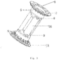
Figs.3-5 are structural schematic diagrams showing different supporting bodies of the present invention; and -
Figs.6-10 are schematic diagrams showing the production process of two parisons. - In the
figures: 1 - supporting end, 2 -supporting body, 3 - convex structure, 4 - supporting end stepped structure, 5-supporting main body, 6 - base, 7 - base hole, 8 - groove, 9 - opening hole, 10-half mold, 11 - preforming mold, 14 -assembly built-in mechanism, 15-supporting body stepped structure, and 16 -cylinder with corrugated structure. - For the sake of further understanding and recognizing the present invention, the present invention will be further described and explained with reference to the embodiments.
- Embodiment 1: Referring to
Figs. 1-5 , a supporting assembly for a hollow tank body includes a supportingbody 2 and supportingends 1 provided at two ends of the supporting body. The supporting ends are provided with stepped transition assemblies connected to the support body. The supportingbody 2 is configured with a hollow structure. The supporting body includes a supportingmain body 5 and a base 6. Each supportingend 1 includes an end surface of circular, elliptical or square shape. The end surface is provided with aconvex structure 3, and the number of the convex structure and the cross-sectional size of each convex structure are configured according to the actual demands of connection strength. The structural design enables the supporting ends to be connected to the wall of the housing body in a simple and fast way, and minimum product materials are required while the high-strength connection performance is satisfied, thereby realizing the objectives of high performance, low cost, and lightweight. The supporting body in the technical solution is configured with a hollow structure, so it has a light weight, stable structure, and needs less materials consumption. Also, the structure can resist the deformation of the hollow tank body under the relatively high overpressure and the low negative pressure. - Embodiment 2: Referring to
Fig. 3 , as an improvement of the present invention, the supporting main body5 is configured with a cylindrical structure or a cylindrical structure with a corrugated structure in the middle. The structure the will not get deformed under the action of external pressure for a long time and is easy to be formed. Accordingly, there are less requirements for developing the molding tools, and time and costs can be saved. - Embodiment 3: Referring to
Fig. 3 , as an improvement of the present invention, the base 6 is configured with a round shape, an elliptical shape or a square shape, and the base is provided with base holes7. The edge is arranged with through holes at the same interval. When the base 6 is connected to the supporting ends, a part of molten material on the supporting ends may pass through the through holes to form a protrusion structure after the molten material is cooled, thereby further improving the connection strength between the supporting ends and the supporting body. - Embodiment 4: Referring to
Fig. 3 , as an improvement of the present invention, a connecting portion of the end surface and the supporting body is provided with a supporting end stepped structure 4.Thesupporting main body is provided with supporting body steppedstructures 15 on the connection portions with the supporting ends at two sides, and the supporting body stepped structure is matched with the supporting end stepped structure to form a stepped transition assembly. The supporting body is provided with radially extending "stepped" edge on the connecting portions with the supporting ends at the two sides to match with the "stepped" structures on the supporting ends. With this design, the contact surface between the supporting ends and the supporting body is increased, while the product materials are saved. The supporting ends are covered on the two sides of the supporting body by an injection molding process. The structural design can increase the connection strength between the supporting ends and the supporting body while reducing the weight of the product. - Embodiment 5: Referring to
Fig. 4 , as an improvement of the present invention, the supporting main body is provided withgrooves 8, and the grooves are V-shaped, U-shaped or semicircle-shaped. The supporting main body is provided with openingholes 9 at positions near the end portions of the two sides, thereby ensuring an inflow and an outflow of a liquid inside the hollow tank body, and a small inner liquid storage space of the hollow body is occupied. The hollow cylinder may also be provided with a plurality of opening holes penetrating through the cylinder body along a plurality of circles around the cylinder, seeFig. 5 . The structure arrangement of grooves and penetrating holes on the hollow cylinder can ensure that the stresses are centralized at the position of the grooves and the penetrating holes where will thus get broken first when the tank body falls down. By doing so, the case where a connecting portion of the supporting structure and a wall of the tank body gets fractured can be avoided, and the integrity of the wall of the tank body can be ensured. If the wall of the tank body is torn, fuel stored inside the tank will leak, which is prone to cause a serious accident. The supporting body may be made of plastic such as POM, HDPE, PA, PPA, PBT, PPS, PEEK or stainless steel metal, and the supporting ends may also be made of plastic such as HDPE, which will facilitate the connection with the upper and lower walls of the fuel tank. - Embodiment 6: Referring to
Figs. 6-10 , a forming method for a hollow tank body having a supporting assembly includes the following steps: - 1) unloading a material from two neck mold devices, see
Fig. 6 ; - 2) moving a preforming mold device to a middle of a mold, see
Fig. 7 ; - 3) after the material is unloaded in place, closing
half molds 10 of the mold and the preformingmold 11, and performing a high-pressure blow molding to preform a housing body, seeFig. 7 ; - 4) after preforming the high-pressure blow molding and preforming, opening the mold, see
Fig. 8 ; - 5) removing the preforming
mold device 11 from the middle, while an assembly built-in mechanism enters a designated position in the middle of the mold, seeFig. 9 ; - 6) connecting an end surface of a connecting component on one side of an internal connecting structure to a designated position of a parison by the assembly built-in mechanism; the action of placing the internal connection structure may also be completed by a robot, see
Fig. 9 ; - 7) removing the assembly built-in mechanism, see
Fig. 10 ; - 8) closing the mold again, and connecting an end surface of a connecting component on the other side of the internal connecting structure to a designated position of a parison at the other side;
- 9) performing a high pressure blowing to complete a final molding of the hollow tank body; and
- 10) opening the mold and taking out a product.
- The internal connecting structure in step (6) includes a supporting assembly and a wave-proof plate structure. When the supporting assembly is connected to the inner wall of the hollow tank body through the assembly built-in mechanism, the end surface of the connecting component on one side of the supporting assembly can be preheated in advance, so as to ensure a sufficient connection with the inner wall of the hollow tank body.
- According to the present invention, the technical features described in
Embodiments Embodiment 1 to form a new embodiment. - It should be noted that the above embodiments are not intended to limit the scope of the present invention, and those equivalent changes or substitutions derived on the basis of the above technical solutions should all be considered as falling within the scope defined by the appended claims of the present invention.
Claims (10)
- A supporting assembly for a hollow tank body, comprising a supporting body and supporting ends provided at two ends of the supporting body, wherein each supporting end is provided with a stepped transition assembly connected to the supporting body.
- The supporting assembly for the hollow tank body of claim 1, wherein the supporting body is configured with a hollow structure.
- The supporting assembly for the hollow tank body of claim 1 or 2, wherein the supporting body comprises a supporting main body and a base.
- The supporting assembly for the hollow tank body of claim 3, wherein the supporting main body is configured with a cylindrical structure or a cylindrical structure with a corrugated structure in a middle.
- The supporting assembly for the hollow tank body of claim 4, wherein the base is configured with a round shape, an elliptical shape, a square shape, or any other shape, and the base is provided with base holes.
- The supporting assembly for the hollow tank body of claim 1 or 2, wherein each supporting end comprises an end surface of a round shape, an elliptical shape, or a square shape, the end surface is provided with a convex structure, a connecting portion of the end surface and the supporting body is provided with a supporting end stepped structure.
- The supporting assembly for the hollow tank body of claim 6, wherein connecting portions between two ends of the supporting main body and the supporting ends are each provided with a supporting body stepped structure, and the supporting body stepped structure is matched with the supporting end stepped structure to form the stepped transition assembly.
- The supporting assembly for the hollow tank body of claim 1 or 2, wherein the supporting main body is provided with grooves, the grooves are V-shaped, U-shaped, or semicircle-shaped, the supporting main body is provided with an opening hole on each of the two sides at a position near an end portion, and the supporting main body is made of a material selected from anyone of POM, HDPE, PA, PPA, PBT, PPS, PEEK and stainless steel metal, and the supporting ends are made of HDPE.
- A forming method for the hollow tank body of the supporting assembly of any one of claims 1-8, comprising:1) unloading a material from two neck mold devices;2) moving a preforming mold device to a middle of a mold;3) after the material is unloaded in place, closing half molds of the mold and the preforming mold, and performing a high-pressure blow molding to preform a housing body;4) after preforming the high-pressure blow molding and preforming for a period of time, opening the mold;5) removing the preforming mold device from the middle, while built-in mechanism enters a designated position in the middle of the mold;6) connecting an end surface of a connecting component on one side of an internal connecting structure to a designated position of a parison by the assembly built-in mechanism;7) removing the assembly built-in mechanism;8) closing the mold again, and connecting an end surface of a connecting component on the other side of the internal connecting structure to a designated position of a parison at the other side;9) performing a high pressure blowing to complete a final molding of the hollow tank body; and10) opening the mold and taking out a product.
- The forming method for the hollow tank body of the supporting assembly of claim 9, wherein the internal connection structure instep (6) comprises the supporting assembly and a wave-proof plate structure, wherein when the supporting assembly is connected to an inner wall of the hollow tank body through the assembly built-in mechanism, an end surface of the connecting component on one side of the supporting assembly is preheated in advance to ensure a sufficient connection with the inner wall of the hollow tank body.
Applications Claiming Priority (3)
| Application Number | Priority Date | Filing Date | Title |
|---|---|---|---|
| CN201620746713.7U CN206106927U (en) | 2016-07-15 | 2016-07-15 | Cavity box support subassembly |
| CN201610557887.3A CN106042904A (en) | 2016-07-15 | 2016-07-15 | Hollow box supporting assembly and hollow box forming method |
| PCT/CN2017/073723 WO2018010427A1 (en) | 2016-07-15 | 2017-02-16 | Supporting assembly for hollow tank body and method for molding hollow tank body |
Publications (3)
| Publication Number | Publication Date |
|---|---|
| EP3486103A1 true EP3486103A1 (en) | 2019-05-22 |
| EP3486103A4 EP3486103A4 (en) | 2020-01-08 |
| EP3486103B1 EP3486103B1 (en) | 2022-12-28 |
Family
ID=60951941
Family Applications (1)
| Application Number | Title | Priority Date | Filing Date |
|---|---|---|---|
| EP17826766.2A Active EP3486103B1 (en) | 2016-07-15 | 2017-02-16 | Supporting assembly for hollow tank body and method for molding hollow tank body |
Country Status (7)
| Country | Link |
|---|---|
| US (1) | US10919378B2 (en) |
| EP (1) | EP3486103B1 (en) |
| JP (1) | JP6800554B2 (en) |
| KR (1) | KR20190032350A (en) |
| MX (1) | MX2019000100A (en) |
| RU (1) | RU2717612C1 (en) |
| WO (1) | WO2018010427A1 (en) |
Cited By (1)
| Publication number | Priority date | Publication date | Assignee | Title |
|---|---|---|---|---|
| EP3878676A4 (en) * | 2018-04-24 | 2023-02-22 | Yapp Automotive Systems Co., Ltd. | BRACKET FOR CONNECTING UPPER AND LOWER SURFACES INSIDE A FUEL TANK |
Families Citing this family (3)
| Publication number | Priority date | Publication date | Assignee | Title |
|---|---|---|---|---|
| DE102016219539A1 (en) * | 2016-10-07 | 2018-04-12 | Kautex Textron Gmbh & Co. Kg | Stiffening element for a fluid container for a motor vehicle and fluid container for a motor vehicle with a stiffening element |
| KR102621556B1 (en) * | 2019-05-22 | 2024-01-04 | 현대자동차주식회사 | Stiffness reinforcement structure for fuel tank of vehicle |
| WO2023008205A1 (en) * | 2021-07-26 | 2023-02-02 | 八千代工業株式会社 | Fuel tank |
Family Cites Families (17)
| Publication number | Priority date | Publication date | Assignee | Title |
|---|---|---|---|---|
| US6135306A (en) * | 1999-02-08 | 2000-10-24 | Salflex Polymers Inc. | Fuel tank anti-deflection device |
| US6338420B1 (en) * | 1999-06-08 | 2002-01-15 | Delphi Technologies, Inc. | Motor vehicle fuel tank and method |
| US6138859A (en) * | 1999-06-08 | 2000-10-31 | Delphi Technologies, Inc. | Fuel tank assembly |
| KR20140022412A (en) * | 2011-04-12 | 2014-02-24 | 이너지 오토모티브 시스템즈 리서치 (소시에떼 아노님) | Fuel tank with improved mechanical resistance |
| DE102011117999B4 (en) * | 2011-11-09 | 2013-06-13 | Kautex Textron Gmbh & Co. Kg | Container for a motor vehicle, in particular fuel or auxiliary fluid container for a motor vehicle and method for producing such a container |
| CN202846875U (en) * | 2012-08-08 | 2013-04-03 | 亚普汽车部件股份有限公司 | Performing template device |
| WO2014023053A1 (en) * | 2012-08-08 | 2014-02-13 | 亚普汽车部件股份有限公司 | Method for forming hollow box body provided with built-in component |
| DE102013003247A1 (en) * | 2013-02-27 | 2014-09-11 | Kautex Textron Gmbh & Co. Kg | Fuel tank |
| CN103286939B (en) * | 2013-05-06 | 2014-07-23 | 亚普汽车部件股份有限公司 | Two-sheet blow molding hollow casing moulding method with auxiliary male mould |
| CN103507263B (en) * | 2013-09-18 | 2016-08-10 | 东风亚普汽车部件有限公司 | The blow molding method of inserts is placed inside multilayer blow moulding plastic fuel tank |
| EP2865553B1 (en) * | 2013-10-25 | 2016-06-22 | Inergy Automotive Systems Research (Société Anonyme) | Tank comprising a reinforcement member and method for manufacturing such a reinforcement member |
| CN204249813U (en) * | 2014-11-07 | 2015-04-08 | 亚普汽车部件股份有限公司 | A kind of have flexible high pressure fuel case supporting construction |
| CN104477027B (en) * | 2014-11-18 | 2018-07-06 | 亚普汽车部件股份有限公司 | Connect the conducting wire rigid-connecting device of fuel tank internal upper and lower surface and the production method of fuel tank |
| JP6381450B2 (en) * | 2015-01-09 | 2018-08-29 | 株式会社Fts | Mounting structure for internal parts of automobile fuel tank |
| CN105539125A (en) * | 2016-02-03 | 2016-05-04 | 亚普汽车部件股份有限公司 | Hollow box body inside reinforcing assembly and hollow box body production method |
| CN105538659A (en) * | 2016-02-03 | 2016-05-04 | 亚普汽车部件股份有限公司 | Connection assembly and forming method of box with same |
| CN106042904A (en) * | 2016-07-15 | 2016-10-26 | 亚普汽车部件股份有限公司 | Hollow box supporting assembly and hollow box forming method |
-
2017
- 2017-02-16 RU RU2019104205A patent/RU2717612C1/en active
- 2017-02-16 US US16/317,561 patent/US10919378B2/en active Active
- 2017-02-16 KR KR1020197000890A patent/KR20190032350A/en not_active Ceased
- 2017-02-16 EP EP17826766.2A patent/EP3486103B1/en active Active
- 2017-02-16 WO PCT/CN2017/073723 patent/WO2018010427A1/en not_active Ceased
- 2017-02-16 JP JP2019501653A patent/JP6800554B2/en active Active
- 2017-02-16 MX MX2019000100A patent/MX2019000100A/en unknown
Cited By (1)
| Publication number | Priority date | Publication date | Assignee | Title |
|---|---|---|---|---|
| EP3878676A4 (en) * | 2018-04-24 | 2023-02-22 | Yapp Automotive Systems Co., Ltd. | BRACKET FOR CONNECTING UPPER AND LOWER SURFACES INSIDE A FUEL TANK |
Also Published As
| Publication number | Publication date |
|---|---|
| MX2019000100A (en) | 2019-06-20 |
| EP3486103A4 (en) | 2020-01-08 |
| US10919378B2 (en) | 2021-02-16 |
| EP3486103B1 (en) | 2022-12-28 |
| WO2018010427A1 (en) | 2018-01-18 |
| BR112019000628A2 (en) | 2019-04-24 |
| US20190232780A1 (en) | 2019-08-01 |
| JP6800554B2 (en) | 2020-12-16 |
| JP2019524535A (en) | 2019-09-05 |
| RU2717612C1 (en) | 2020-03-24 |
| KR20190032350A (en) | 2019-03-27 |
Similar Documents
| Publication | Publication Date | Title |
|---|---|---|
| EP3486103B1 (en) | Supporting assembly for hollow tank body and method for molding hollow tank body | |
| CN106042904A (en) | Hollow box supporting assembly and hollow box forming method | |
| CN104477027B (en) | Connect the conducting wire rigid-connecting device of fuel tank internal upper and lower surface and the production method of fuel tank | |
| CN105539125A (en) | Hollow box body inside reinforcing assembly and hollow box body production method | |
| CN108382195A (en) | Connect the supporter of fuel tank internal upper and lower surface | |
| US20180311880A1 (en) | Rigid connecting device for connecting the upper and lower surfaces inside an oil tank and production method of the oil tank | |
| CN109203980B (en) | A new type of internal box support for high-pressure plastic fuel tank | |
| CN105538659A (en) | Connection assembly and forming method of box with same | |
| JP2022503351A (en) | A support that connects the upper and lower surfaces inside the oil tank | |
| CN116550866A (en) | Explosion-proof valve integrated forming process of top cover sheet and top cover sheet with explosion-proof valve | |
| US7985496B2 (en) | Side terminal and insert, method and apparatus for manufacturing same | |
| CN206106927U (en) | Cavity box support subassembly | |
| CN102802993A (en) | Resin fuel tank | |
| CN205523672U (en) | Inside reinforcing subassembly of cavity box | |
| CN109177725A (en) | A kind of the coaming plate welded type washboard and its welding method of tradition blow molding fuel tank | |
| CN104986033B (en) | Fuel tank molded rigid component and fuel tank forming method | |
| CN103658208A (en) | One-step forming technology of nozzle of nuclear power main-steam super pipeline | |
| KR20120038129A (en) | Manufacturing method of fuel tank, and fuel tank thereof | |
| GB2236288A (en) | A plastics fuel tank, e.g. for a vehicle | |
| JP2019188895A (en) | Fuel tank | |
| CN210760239U (en) | Fuel storage box inner wall butt fusion structure | |
| CN207522969U (en) | a mold | |
| CN115634986B (en) | Air spring housing manufacturing method, air spring housing and automobile | |
| WO2024200635A1 (en) | Thermoplastic tank and method for manufacturing the thermoplastic tank | |
| CN212425879U (en) | Electron tube core column welding mould |
Legal Events
| Date | Code | Title | Description |
|---|---|---|---|
| STAA | Information on the status of an ep patent application or granted ep patent |
Free format text: STATUS: THE INTERNATIONAL PUBLICATION HAS BEEN MADE |
|
| PUAI | Public reference made under article 153(3) epc to a published international application that has entered the european phase |
Free format text: ORIGINAL CODE: 0009012 |
|
| STAA | Information on the status of an ep patent application or granted ep patent |
Free format text: STATUS: REQUEST FOR EXAMINATION WAS MADE |
|
| 17P | Request for examination filed |
Effective date: 20190213 |
|
| AK | Designated contracting states |
Kind code of ref document: A1 Designated state(s): AL AT BE BG CH CY CZ DE DK EE ES FI FR GB GR HR HU IE IS IT LI LT LU LV MC MK MT NL NO PL PT RO RS SE SI SK SM TR |
|
| AX | Request for extension of the european patent |
Extension state: BA ME |
|
| DAV | Request for validation of the european patent (deleted) | ||
| DAX | Request for extension of the european patent (deleted) | ||
| A4 | Supplementary search report drawn up and despatched |
Effective date: 20191211 |
|
| RIC1 | Information provided on ipc code assigned before grant |
Ipc: B29C 49/20 20060101ALI20191205BHEP Ipc: B29C 49/18 20060101ALI20191205BHEP Ipc: B60K 15/03 20060101AFI20191205BHEP |
|
| GRAP | Despatch of communication of intention to grant a patent |
Free format text: ORIGINAL CODE: EPIDOSNIGR1 |
|
| STAA | Information on the status of an ep patent application or granted ep patent |
Free format text: STATUS: GRANT OF PATENT IS INTENDED |
|
| INTG | Intention to grant announced |
Effective date: 20220818 |
|
| GRAS | Grant fee paid |
Free format text: ORIGINAL CODE: EPIDOSNIGR3 |
|
| GRAA | (expected) grant |
Free format text: ORIGINAL CODE: 0009210 |
|
| STAA | Information on the status of an ep patent application or granted ep patent |
Free format text: STATUS: THE PATENT HAS BEEN GRANTED |
|
| AK | Designated contracting states |
Kind code of ref document: B1 Designated state(s): AL AT BE BG CH CY CZ DE DK EE ES FI FR GB GR HR HU IE IS IT LI LT LU LV MC MK MT NL NO PL PT RO RS SE SI SK SM TR |
|
| REG | Reference to a national code |
Ref country code: GB Ref legal event code: FG4D |
|
| REG | Reference to a national code |
Ref country code: CH Ref legal event code: EP |
|
| REG | Reference to a national code |
Ref country code: DE Ref legal event code: R096 Ref document number: 602017065073 Country of ref document: DE |
|
| REG | Reference to a national code |
Ref country code: AT Ref legal event code: REF Ref document number: 1540256 Country of ref document: AT Kind code of ref document: T Effective date: 20230115 |
|
| REG | Reference to a national code |
Ref country code: IE Ref legal event code: FG4D |
|
| REG | Reference to a national code |
Ref country code: LT Ref legal event code: MG9D |
|
| PG25 | Lapsed in a contracting state [announced via postgrant information from national office to epo] |
Ref country code: SE Free format text: LAPSE BECAUSE OF FAILURE TO SUBMIT A TRANSLATION OF THE DESCRIPTION OR TO PAY THE FEE WITHIN THE PRESCRIBED TIME-LIMIT Effective date: 20221228 Ref country code: NO Free format text: LAPSE BECAUSE OF FAILURE TO SUBMIT A TRANSLATION OF THE DESCRIPTION OR TO PAY THE FEE WITHIN THE PRESCRIBED TIME-LIMIT Effective date: 20230328 Ref country code: LT Free format text: LAPSE BECAUSE OF FAILURE TO SUBMIT A TRANSLATION OF THE DESCRIPTION OR TO PAY THE FEE WITHIN THE PRESCRIBED TIME-LIMIT Effective date: 20221228 Ref country code: FI Free format text: LAPSE BECAUSE OF FAILURE TO SUBMIT A TRANSLATION OF THE DESCRIPTION OR TO PAY THE FEE WITHIN THE PRESCRIBED TIME-LIMIT Effective date: 20221228 |
|
| REG | Reference to a national code |
Ref country code: NL Ref legal event code: MP Effective date: 20221228 |
|
| REG | Reference to a national code |
Ref country code: AT Ref legal event code: MK05 Ref document number: 1540256 Country of ref document: AT Kind code of ref document: T Effective date: 20221228 |
|
| PG25 | Lapsed in a contracting state [announced via postgrant information from national office to epo] |
Ref country code: RS Free format text: LAPSE BECAUSE OF FAILURE TO SUBMIT A TRANSLATION OF THE DESCRIPTION OR TO PAY THE FEE WITHIN THE PRESCRIBED TIME-LIMIT Effective date: 20221228 Ref country code: LV Free format text: LAPSE BECAUSE OF FAILURE TO SUBMIT A TRANSLATION OF THE DESCRIPTION OR TO PAY THE FEE WITHIN THE PRESCRIBED TIME-LIMIT Effective date: 20221228 Ref country code: HR Free format text: LAPSE BECAUSE OF FAILURE TO SUBMIT A TRANSLATION OF THE DESCRIPTION OR TO PAY THE FEE WITHIN THE PRESCRIBED TIME-LIMIT Effective date: 20221228 Ref country code: GR Free format text: LAPSE BECAUSE OF FAILURE TO SUBMIT A TRANSLATION OF THE DESCRIPTION OR TO PAY THE FEE WITHIN THE PRESCRIBED TIME-LIMIT Effective date: 20230329 |
|
| PG25 | Lapsed in a contracting state [announced via postgrant information from national office to epo] |
Ref country code: NL Free format text: LAPSE BECAUSE OF FAILURE TO SUBMIT A TRANSLATION OF THE DESCRIPTION OR TO PAY THE FEE WITHIN THE PRESCRIBED TIME-LIMIT Effective date: 20221228 |
|
| PG25 | Lapsed in a contracting state [announced via postgrant information from national office to epo] |
Ref country code: SM Free format text: LAPSE BECAUSE OF FAILURE TO SUBMIT A TRANSLATION OF THE DESCRIPTION OR TO PAY THE FEE WITHIN THE PRESCRIBED TIME-LIMIT Effective date: 20221228 Ref country code: RO Free format text: LAPSE BECAUSE OF FAILURE TO SUBMIT A TRANSLATION OF THE DESCRIPTION OR TO PAY THE FEE WITHIN THE PRESCRIBED TIME-LIMIT Effective date: 20221228 Ref country code: PT Free format text: LAPSE BECAUSE OF FAILURE TO SUBMIT A TRANSLATION OF THE DESCRIPTION OR TO PAY THE FEE WITHIN THE PRESCRIBED TIME-LIMIT Effective date: 20230428 Ref country code: ES Free format text: LAPSE BECAUSE OF FAILURE TO SUBMIT A TRANSLATION OF THE DESCRIPTION OR TO PAY THE FEE WITHIN THE PRESCRIBED TIME-LIMIT Effective date: 20221228 Ref country code: EE Free format text: LAPSE BECAUSE OF FAILURE TO SUBMIT A TRANSLATION OF THE DESCRIPTION OR TO PAY THE FEE WITHIN THE PRESCRIBED TIME-LIMIT Effective date: 20221228 Ref country code: AT Free format text: LAPSE BECAUSE OF FAILURE TO SUBMIT A TRANSLATION OF THE DESCRIPTION OR TO PAY THE FEE WITHIN THE PRESCRIBED TIME-LIMIT Effective date: 20221228 |
|
| P01 | Opt-out of the competence of the unified patent court (upc) registered |
Effective date: 20230623 |
|
| PG25 | Lapsed in a contracting state [announced via postgrant information from national office to epo] |
Ref country code: SK Free format text: LAPSE BECAUSE OF FAILURE TO SUBMIT A TRANSLATION OF THE DESCRIPTION OR TO PAY THE FEE WITHIN THE PRESCRIBED TIME-LIMIT Effective date: 20221228 Ref country code: PL Free format text: LAPSE BECAUSE OF FAILURE TO SUBMIT A TRANSLATION OF THE DESCRIPTION OR TO PAY THE FEE WITHIN THE PRESCRIBED TIME-LIMIT Effective date: 20221228 Ref country code: IS Free format text: LAPSE BECAUSE OF FAILURE TO SUBMIT A TRANSLATION OF THE DESCRIPTION OR TO PAY THE FEE WITHIN THE PRESCRIBED TIME-LIMIT Effective date: 20230428 Ref country code: AL Free format text: LAPSE BECAUSE OF FAILURE TO SUBMIT A TRANSLATION OF THE DESCRIPTION OR TO PAY THE FEE WITHIN THE PRESCRIBED TIME-LIMIT Effective date: 20221228 |
|
| PG25 | Lapsed in a contracting state [announced via postgrant information from national office to epo] |
Ref country code: MC Free format text: LAPSE BECAUSE OF FAILURE TO SUBMIT A TRANSLATION OF THE DESCRIPTION OR TO PAY THE FEE WITHIN THE PRESCRIBED TIME-LIMIT Effective date: 20221228 |
|
| REG | Reference to a national code |
Ref country code: CH Ref legal event code: PL Ref country code: DE Ref legal event code: R097 Ref document number: 602017065073 Country of ref document: DE |
|
| REG | Reference to a national code |
Ref country code: BE Ref legal event code: MM Effective date: 20230228 |
|
| PG25 | Lapsed in a contracting state [announced via postgrant information from national office to epo] |
Ref country code: LU Free format text: LAPSE BECAUSE OF NON-PAYMENT OF DUE FEES Effective date: 20230216 Ref country code: LI Free format text: LAPSE BECAUSE OF NON-PAYMENT OF DUE FEES Effective date: 20230228 Ref country code: DK Free format text: LAPSE BECAUSE OF FAILURE TO SUBMIT A TRANSLATION OF THE DESCRIPTION OR TO PAY THE FEE WITHIN THE PRESCRIBED TIME-LIMIT Effective date: 20221228 Ref country code: CH Free format text: LAPSE BECAUSE OF NON-PAYMENT OF DUE FEES Effective date: 20230228 |
|
| PLBE | No opposition filed within time limit |
Free format text: ORIGINAL CODE: 0009261 |
|
| STAA | Information on the status of an ep patent application or granted ep patent |
Free format text: STATUS: NO OPPOSITION FILED WITHIN TIME LIMIT |
|
| GBPC | Gb: european patent ceased through non-payment of renewal fee |
Effective date: 20230328 |
|
| 26N | No opposition filed |
Effective date: 20230929 |
|
| REG | Reference to a national code |
Ref country code: IE Ref legal event code: MM4A |
|
| PG25 | Lapsed in a contracting state [announced via postgrant information from national office to epo] |
Ref country code: GB Free format text: LAPSE BECAUSE OF NON-PAYMENT OF DUE FEES Effective date: 20230328 |
|
| PG25 | Lapsed in a contracting state [announced via postgrant information from national office to epo] |
Ref country code: SI Free format text: LAPSE BECAUSE OF FAILURE TO SUBMIT A TRANSLATION OF THE DESCRIPTION OR TO PAY THE FEE WITHIN THE PRESCRIBED TIME-LIMIT Effective date: 20221228 Ref country code: IE Free format text: LAPSE BECAUSE OF NON-PAYMENT OF DUE FEES Effective date: 20230216 Ref country code: GB Free format text: LAPSE BECAUSE OF NON-PAYMENT OF DUE FEES Effective date: 20230328 |
|
| PG25 | Lapsed in a contracting state [announced via postgrant information from national office to epo] |
Ref country code: BE Free format text: LAPSE BECAUSE OF NON-PAYMENT OF DUE FEES Effective date: 20230228 |
|
| PG25 | Lapsed in a contracting state [announced via postgrant information from national office to epo] |
Ref country code: IT Free format text: LAPSE BECAUSE OF FAILURE TO SUBMIT A TRANSLATION OF THE DESCRIPTION OR TO PAY THE FEE WITHIN THE PRESCRIBED TIME-LIMIT Effective date: 20221228 |
|
| PG25 | Lapsed in a contracting state [announced via postgrant information from national office to epo] |
Ref country code: BG Free format text: LAPSE BECAUSE OF FAILURE TO SUBMIT A TRANSLATION OF THE DESCRIPTION OR TO PAY THE FEE WITHIN THE PRESCRIBED TIME-LIMIT Effective date: 20221228 |
|
| PG25 | Lapsed in a contracting state [announced via postgrant information from national office to epo] |
Ref country code: BG Free format text: LAPSE BECAUSE OF FAILURE TO SUBMIT A TRANSLATION OF THE DESCRIPTION OR TO PAY THE FEE WITHIN THE PRESCRIBED TIME-LIMIT Effective date: 20221228 |
|
| PG25 | Lapsed in a contracting state [announced via postgrant information from national office to epo] |
Ref country code: CY Free format text: LAPSE BECAUSE OF FAILURE TO SUBMIT A TRANSLATION OF THE DESCRIPTION OR TO PAY THE FEE WITHIN THE PRESCRIBED TIME-LIMIT; INVALID AB INITIO Effective date: 20170216 |
|
| PG25 | Lapsed in a contracting state [announced via postgrant information from national office to epo] |
Ref country code: HU Free format text: LAPSE BECAUSE OF FAILURE TO SUBMIT A TRANSLATION OF THE DESCRIPTION OR TO PAY THE FEE WITHIN THE PRESCRIBED TIME-LIMIT; INVALID AB INITIO Effective date: 20170216 |
|
| PG25 | Lapsed in a contracting state [announced via postgrant information from national office to epo] |
Ref country code: TR Free format text: LAPSE BECAUSE OF FAILURE TO SUBMIT A TRANSLATION OF THE DESCRIPTION OR TO PAY THE FEE WITHIN THE PRESCRIBED TIME-LIMIT Effective date: 20221228 |
|
| PGFP | Annual fee paid to national office [announced via postgrant information from national office to epo] |
Ref country code: DE Payment date: 20260206 Year of fee payment: 10 |
|
| PGFP | Annual fee paid to national office [announced via postgrant information from national office to epo] |
Ref country code: FR Payment date: 20260227 Year of fee payment: 10 |
|
| PGFP | Annual fee paid to national office [announced via postgrant information from national office to epo] |
Ref country code: CZ Payment date: 20260130 Year of fee payment: 10 |