EP3486075A1 - Fiber wound body, fiber-reinforced resin material, and method for manufacturing fiber wound body - Google Patents
Fiber wound body, fiber-reinforced resin material, and method for manufacturing fiber wound body Download PDFInfo
- Publication number
- EP3486075A1 EP3486075A1 EP17827355.3A EP17827355A EP3486075A1 EP 3486075 A1 EP3486075 A1 EP 3486075A1 EP 17827355 A EP17827355 A EP 17827355A EP 3486075 A1 EP3486075 A1 EP 3486075A1
- Authority
- EP
- European Patent Office
- Prior art keywords
- reinforced
- fiber yarns
- fiber
- reinforced fiber
- cross
- Prior art date
- Legal status (The legal status is an assumption and is not a legal conclusion. Google has not performed a legal analysis and makes no representation as to the accuracy of the status listed.)
- Granted
Links
Images



Classifications
-
- C—CHEMISTRY; METALLURGY
- C08—ORGANIC MACROMOLECULAR COMPOUNDS; THEIR PREPARATION OR CHEMICAL WORKING-UP; COMPOSITIONS BASED THEREON
- C08J—WORKING-UP; GENERAL PROCESSES OF COMPOUNDING; AFTER-TREATMENT NOT COVERED BY SUBCLASSES C08B, C08C, C08F, C08G or C08H
- C08J5/00—Manufacture of articles or shaped materials containing macromolecular substances
- C08J5/24—Impregnating materials with prepolymers which can be polymerised in situ, e.g. manufacture of prepregs
-
- B—PERFORMING OPERATIONS; TRANSPORTING
- B29—WORKING OF PLASTICS; WORKING OF SUBSTANCES IN A PLASTIC STATE IN GENERAL
- B29C—SHAPING OR JOINING OF PLASTICS; SHAPING OF MATERIAL IN A PLASTIC STATE, NOT OTHERWISE PROVIDED FOR; AFTER-TREATMENT OF THE SHAPED PRODUCTS, e.g. REPAIRING
- B29C70/00—Shaping composites, i.e. plastics material comprising reinforcements, fillers or preformed parts, e.g. inserts
- B29C70/04—Shaping composites, i.e. plastics material comprising reinforcements, fillers or preformed parts, e.g. inserts comprising reinforcements only, e.g. self-reinforcing plastics
- B29C70/28—Shaping operations therefor
- B29C70/30—Shaping by lay-up, i.e. applying fibres, tape or broadsheet on a mould, former or core; Shaping by spray-up, i.e. spraying of fibres on a mould, former or core
- B29C70/32—Shaping by lay-up, i.e. applying fibres, tape or broadsheet on a mould, former or core; Shaping by spray-up, i.e. spraying of fibres on a mould, former or core on a rotating mould, former or core
-
- B—PERFORMING OPERATIONS; TRANSPORTING
- B29—WORKING OF PLASTICS; WORKING OF SUBSTANCES IN A PLASTIC STATE IN GENERAL
- B29C—SHAPING OR JOINING OF PLASTICS; SHAPING OF MATERIAL IN A PLASTIC STATE, NOT OTHERWISE PROVIDED FOR; AFTER-TREATMENT OF THE SHAPED PRODUCTS, e.g. REPAIRING
- B29C70/00—Shaping composites, i.e. plastics material comprising reinforcements, fillers or preformed parts, e.g. inserts
- B29C70/04—Shaping composites, i.e. plastics material comprising reinforcements, fillers or preformed parts, e.g. inserts comprising reinforcements only, e.g. self-reinforcing plastics
- B29C70/06—Fibrous reinforcements only
- B29C70/10—Fibrous reinforcements only characterised by the structure of fibrous reinforcements, e.g. hollow fibres
- B29C70/16—Fibrous reinforcements only characterised by the structure of fibrous reinforcements, e.g. hollow fibres using fibres of substantial or continuous length
- B29C70/24—Fibrous reinforcements only characterised by the structure of fibrous reinforcements, e.g. hollow fibres using fibres of substantial or continuous length oriented in at least three directions forming a three-dimensional [3D] structure
-
- D—TEXTILES; PAPER
- D04—BRAIDING; LACE-MAKING; KNITTING; TRIMMINGS; NON-WOVEN FABRICS
- D04C—BRAIDING OR MANUFACTURE OF LACE, INCLUDING BOBBIN-NET OR CARBONISED LACE; BRAIDING MACHINES; BRAID; LACE
- D04C1/00—Braid or lace, e.g. pillow-lace; Processes for the manufacture thereof
- D04C1/06—Braid or lace serving particular purposes
-
- D—TEXTILES; PAPER
- D10—INDEXING SCHEME ASSOCIATED WITH SUBLASSES OF SECTION D, RELATING TO TEXTILES
- D10B—INDEXING SCHEME ASSOCIATED WITH SUBLASSES OF SECTION D, RELATING TO TEXTILES
- D10B2401/00—Physical properties
- D10B2401/06—Load-responsive characteristics
-
- D—TEXTILES; PAPER
- D10—INDEXING SCHEME ASSOCIATED WITH SUBLASSES OF SECTION D, RELATING TO TEXTILES
- D10B—INDEXING SCHEME ASSOCIATED WITH SUBLASSES OF SECTION D, RELATING TO TEXTILES
- D10B2403/00—Details of fabric structure established in the fabric forming process
- D10B2403/02—Cross-sectional features
- D10B2403/024—Fabric incorporating additional compounds
- D10B2403/0241—Fabric incorporating additional compounds enhancing mechanical properties
- D10B2403/02411—Fabric incorporating additional compounds enhancing mechanical properties with a single array of unbent yarn, e.g. unidirectional reinforcement fabrics
-
- D—TEXTILES; PAPER
- D10—INDEXING SCHEME ASSOCIATED WITH SUBLASSES OF SECTION D, RELATING TO TEXTILES
- D10B—INDEXING SCHEME ASSOCIATED WITH SUBLASSES OF SECTION D, RELATING TO TEXTILES
- D10B2505/00—Industrial
- D10B2505/02—Reinforcing materials; Prepregs
Definitions
- the present invention relates to a fiber wound body used, for example, as a fiber-reinforced base of a load energy absorbing material, a fiber-reinforced resin material in which a fiber wound body is used as a fiber-reinforced base, and a method for manufacturing a fiber wound body.
- a fiber-reinforced resin material is used as a light, strong material.
- a fiber-reinforced resin material includes a compound of a fiber-reinforced base and a matrix of, for example, resin
- the dynamic properties (mechanical properties) are improved as compared to the matrix itself.
- the fiber-reinforced base of a fiber-reinforced resin material includes, for example, a fiber wound body manufactured through filament winding (FW) or braiding (braid).
- the fiber wound body is manufactured by winding a number of reinforced-fiber yarns about a winding axis to have a tubular or solid structure.
- a fiber-reinforced resin material is used as, for example, a load energy absorbing material.
- the load energy absorbing material is used as, for example, a crash box arranged between a bumper and a frame of a vehicle body
- the crash box generally needs to have a required mechanical strength to hold its position. Additionally, when an impact load exceeding the designed value is applied, the crash box needs to deform and collapse while absorbing the impact load.
- the strength of the crash box is lowest in the distal portion, which is a portion that first receives an impact load, and gradually increases toward the basal portion.
- the cross section of a reinforced fiber yarn may be increased toward the basal portion of the fiber-reinforced base to gradually vary the strength.
- patent document 1 discloses a tubular fiber body having a transversal cross section, the shape of which changes along its length. The strength is varied by using a thick fiber yarn in a portion having a large diameter and a thin fiber yarn in a portion having a small diameter.
- Patent Document 1 Japanese National Phase Laid-Open Patent Publication No. 2014-508666
- a fiber wound body includes reinforced fiber yarns wound about a winding axis.
- Each of the reinforced fiber yarns includes a gradual cross-section change portion.
- the gradual cross-section change portion has a fiber content rate that is constant in a longitudinal direction of the yarn and has a cross section that gradually changes.
- a fiber-reinforced resin material includes the fiber wound body described above and a matrix resin.
- the fiber wound body is a fiber-reinforced base.
- a method for manufacturing a fiber wound body includes elongating each of reinforced fiber yarns having a cross section constant in a longitudinal direction of the yarn in one direction with a drafting device including roller groups; when elongating the reinforced fiber yarns in one direction, forming a gradual cross-section change portion having a fiber content rate that is constant in the longitudinal direction of the yarn and having a cross section that gradually changes by continuously varying a drafting rate of the drafting device to continuously change the cross section of the reinforced fiber yarns in the one direction; and obtaining a fiber wound body by winding the reinforced fiber yarns including the gradual cross-section change portions about a winding axis.
- a first embodiment of a fiber wound body, a fiber-reinforced resin material, and a method for manufacturing a fiber wound body will now be described with reference to Figs. 1 to 5 .
- Fig. 1 shows a load energy absorbing material 10 used as a fiber-reinforced resin material.
- the load energy absorbing material 10 includes a tubular braid 11, which is a fiber wound body used as a fiber-reinforced base, and a matrix resin.
- the tubular braid 11 is shaped as a tubular cone in a structure braided by first reinforced fiber yarns 12, second reinforced fiber yarns 13, and third reinforced fiber yarns 14.
- the tubular braid 11 has an axial end including a basal portion 11a and the other axial end including a distal portion 11b.
- a direction in which a winding axis L extends refers to the axial direction.
- the first reinforced fiber yarns 12 are arranged parallel to each other.
- the second reinforced fiber yarns 13 are arranged parallel to each other and intersect with the first reinforced fiber yarns 12.
- the third reinforced fiber yarns 14 are arranged parallel to each other and intersect with the first reinforced fiber yarns 12 and the second reinforced fiber yarns 13.
- An angle at which the third reinforced fiber yarns 14 intersect with the first reinforced fiber yarns 12 is equal to an angle at which the third reinforced fiber yarns 14 intersect with the second reinforced fiber yarns 13.
- the third reinforced fiber yarns 14 are arranged in a generatrix direction of the cone.
- the tubular braid 11 has a structure in which the first reinforced fiber yarns 12 and the second reinforced fiber yarns 13 are wound around the third reinforced fiber yarns 14.
- the first reinforced fiber yarns 12 and the second reinforced fiber yarns 13 are wound about the winding axis L.
- the first reinforced fiber yarns 12 and the second reinforced fiber yarns 13 are configured to be oblique yarn lines in the tubular braid 11.
- the third reinforced fiber yarns 14 are configured to be axial yarn lines in the tubular braid 11.
- the first reinforced fiber yarns 12 are arranged to intersect with the winding axis L of the tubular braid 11 at an oblique angle ⁇ .
- the second reinforced fiber yarns 13 are arranged to intersect with the winding axis L of the tubular braid 11 at an angle - ⁇ , which is opposite to the oblique angle ⁇ .
- the oblique angle ⁇ is set in accordance with, for example, the shape of the tubular braid 11 and the required strength.
- the first to third reinforced fiber yarns 12 to 14 are formed by spinning non-continuous fibers.
- the first to third reinforced fiber yarns 12 to 14 are formed of carbon fibers, but may be formed of glass fibers or resin fibers.
- the first to third reinforced fiber yarns 12 to 14 include gradual cross-section change portions 20, each of which has a cross section that continuously decreases from the basal portion 11a toward the distal portion 11b of the tubular braid 11.
- the cross section of the reinforced fiber yarns 12 to 14 refers to the lateral dimension and the transverse dimension of a low-profile cross section of the reinforced fiber yarns 12 to 14.
- continuous change in the cross section of a gradual cross-section change portion 20 refers to continuous change in both the lateral dimension and the transverse dimension of the gradual cross-section change portion 20.
- one of the lateral dimension and the transverse dimension of the gradual cross-section change portion 20 may be fixed while the other dimension continuously changes.
- the tubular braid 11 includes a gradual thickness change portion 18.
- the thickness of the gradual thickness change portion 18 increases toward the basal portion 11a. That is, the thickness of the gradual thickness change portion 18 decreases toward the distal portion 11b.
- the thickness of the tubular braid 11 gradually decreases from the basal portion 11a toward the distal portion 11b along the winding axis L.
- Each of the reinforced fiber yarns 12 to 14 has a fiber content rate that is the same at any position in a longitudinal direction of the yarn. Accordingly, the tubular braid 11 has a fiber content rate that is the same at any position in the axial direction.
- the fiber content rate of each of the reinforced fiber yarns 12 to 14 refers to the proportion of fibers occupied in the total cross-sectional area of the respective the reinforced fiber yarns 12 to 14.
- the tubular braid 11 having the configuration described above is manufactured using a braider (braiding device) including a drafting device.
- a braider 30 includes first oblique yarn feeders 32a and second oblique yarn feeders 32b.
- the first reinforced fiber yarns 12 are fed out of the first oblique yarn feeders 32a to a circumferential surface of a mandrel 31 at a predetermined angle with respect to the axis of the mandrel 31.
- the second reinforced fiber yarns 13 are fed out of the second oblique yarn feeders 32b to the circumferential surface of the mandrel 31 at a predetermined angle with respect to the axis of the mandrel 31.
- the first reinforced fiber yarns 12 fed out of the first oblique yarn feeders 32a are provided to the mandrel 31 at an angle + ⁇ .
- the second reinforced fiber yarns 13 fed out of the second oblique yarn feeders 32b are provided to the mandrel 31 at an angle - ⁇ .
- the predetermined angle is 45°.
- the oblique yarn feeders 32a and 32b feed out the reinforced fiber yarns 12 and 13 that do not include the gradual cross-section change portions 20 and thus have a constant cross section.
- the braider 30 includes axial yarn feeders 33.
- the third reinforced fiber yarns 14 are fed out of the axial yarn feeders 33 and arranged in the axial direction of the mandrel 31.
- the axial yarn feeders 33 feed out the third reinforced fiber yarns 14 that do not have the gradual cross-section change portions 20 and thus have a constant cross section.
- the braider 30 includes drafting devices 40.
- the drafting devices 40 are arranged at a downstream side of the feeders 32a, 32b, and 33 in a direction in which the oblique yarn feeders 32a and 32b and the axial yarn feeders 33 feed the reinforced fiber yarns 12 to 14.
- the drafting devices 40 respectively receive the reinforced fiber yarns 12 to 14 from the feeders 32a, 32b, and 33 and elongate the reinforced fiber yarns 12 to 14.
- each of the drafting devices 40 includes a front roller group 42 and a back roller group 43.
- the front roller group 42 includes rollers 42a.
- the back roller group 43 includes rollers 43a.
- the reinforced fiber yarns 12 to 14 are elongated so that the cross section of the reinforced fiber yarns 12 to 14 gradually decreases toward the downstream side in the feeding direction.
- each of the reinforced fiber yarns 12 to 14 has a cross section that gradually decreases and includes the gradual cross-section change portion 20.
- the drafting rate is lower toward the upstream side in the feeding direction.
- the cross section of the reinforced fiber yarns 12 to 14 remains close to the cross section of the reinforced fiber yarns 12 to 14 that have not been elongated.
- the tubular braid 11 is obtained.
- the obtained tubular braid 11 is impregnated with a thermosetting resin and cured to manufacture the load energy absorbing material 10.
- the impregnation and curing of the resin is performed through resin transfer molding (RTM) but may be performed through a process other than resin transfer molding (RTM).
- the thickness of the tubular braid 11 gradually increases from the distal portion 11b toward the basal portion 11a in the axial direction because of the gradual thickness change portion 18.
- the strength of the load energy absorbing material 10 is lowest in the distal portion, which corresponds to the distal portion 11b of the tubular braid 11.
- the strength of the load energy absorbing material 10 gradually increases from the distal portion 11b toward the basal portion 11a in the axial direction of the tubular braid 11.
- the embodiment has the operation and advantages described below.
- a second embodiment of a fiber wound body, a fiber-reinforced resin material, and a method for manufacturing a fiber wound body will now be described with reference to Figs. 6 to 9 .
- the same reference characters are given to those elements that are the same as the corresponding elements of the first embodiment. Such elements will not be described in detail.
- a second embodiment of a load energy absorbing material 70 used as a fiber-reinforced resin material includes a fiber wound body 51, which is used as the fiber-reinforced base, and a matrix resin.
- the fiber wound body 51 is tubular.
- the fiber wound body 51 has a structure in which a first fiber layer 54, which is an inner layer formed by a first reinforced fiber yarn 52, and a second fiber layer 55, which is an outer layer formed by a second reinforced fiber yarn 53 at a radially outer side of the first fiber layer 54, are stacked on each other.
- a direction in which the winding axis L extends refers to the axial direction.
- the fiber wound body 51 has an axial end including a basal portion 51a and the other axial end including a distal portion 51b.
- the first reinforced fiber yarn 52 is wound to intersect with the winding axis L of the fiber wound body 51 at an angle ⁇ .
- the second reinforced fiber yarn 53 is wound to intersect with the winding axis L of the fiber wound body 51 at the angle ⁇ .
- the intersecting angle ⁇ of each of the reinforced fiber yarns 52 and 53 is set in accordance with, for example, the shape of the fiber wound body 51 and the required strength.
- the first and second reinforced fiber yarns 52 and 53 are obtained by spinning non-continuous fibers.
- the first and second reinforced fiber yarns 52 and 53 are formed by carbon fibers but may be formed of glass fibers or resin fibers.
- the first reinforced fiber yarn 52 and the second reinforced fiber yarn 53 each include a gradual cross-section change portion 56 having a cross section that continuously decreases from the basal portion 51a toward the distal portion 51b of the fiber wound body 51.
- the fiber wound body 51 includes a gradual thickness change portion 57.
- the thickness of the gradual thickness change portion 57 increases toward the basal portion 51a and decreases toward the distal portion 51b.
- the thickness of the fiber wound body 51 is gradually decreased by the gradual thickness change portion 57 from the basal portion 51a toward the distal portion 51b along the winding axis L.
- the cross section of the gradual cross-section change portion 56 regularly decreases from a thick part toward a thin part of the gradual thickness change portion 57. Even when the thickness of the fiber wound body 51 is changed, the gradual thickness change portion 57 is formed by the gradual cross-section change portions 56 of the reinforced fiber yarns 52 and 53.
- each of the reinforced fiber yarns 52 and 53 has a fiber content rate that is the same at any position in a longitudinal direction of the yarn. Accordingly, the fiber wound body 51 has a fiber content rate that is the same at any position in the axial direction.
- the fiber wound body 51 is tapered so that the outer diameter gradually decreases from the basal portion 51a toward the distal portion 51b.
- the inner diameter of the fiber wound body 51 is constant from the basal portion 51a toward the distal portion 51b.
- the fiber wound body 51 is manufactured through filament winding.
- a filament winding device 60 manufacturing the fiber wound body 51 includes a mandrel 61, a feeding head 62, a resin bath 63, a drafting device 64, and a bobbin 65.
- the drafting device 64 includes a front roller and a back roller.
- the reinforced fiber yarns 52 and 53 that do not include the gradual cross-section change portion 56 and thus have a constant cross section are wound around the bobbin 65.
- the reinforced fiber yarns 52 and 53 When fed out of the bobbin 65, the reinforced fiber yarns 52 and 53 are elongated by the drafting device 64. As the reinforced fiber yarns 52 and 53 move from the bobbin 65 toward the downstream side in the feeding direction, the reinforced fiber yarns 52 and 53 are elongated so that the cross section gradually decreases. When the cross section of each of the reinforced fiber yarns 52 and 53 is gradually decreased, the gradual cross-section change portion 56 is manufactured.
- the reinforced fiber yarns 52 and 53 including the gradual cross-section change portions 56 are impregnated with a resin in the resin bath 63 and then directed to the feeding head 62.
- the reinforced fiber yarns 52 and 53 impregnated with the resin in the resin bath 63 are wound around a mandrel 61 via the feeding head 62. At this time, angles at which the reinforced fiber yarns 52 and 53 are wound around the mandrel 61 are adjusted.
- the beginning of winding in the fiber wound body 51 corresponds to the basal portion 51a.
- the reinforced fiber yarns 52 and 53 are elongated by the drafting device 64 so that the cross section gradually decreases, the reinforced fiber yarns 52 and 53 are wound around the mandrel 61.
- the gradual cross-section change portion 56 is manufactured.
- the drafting rate of the reinforced fiber yarns 52 and 53 is lower toward the beginning of winding.
- the cross section of the reinforced fiber yarns 52 and 53 is closer to the cross section of the reinforced fiber yarns 52 and 53 that have not been elongated at positions toward the beginning of winding.
- the thickness of the fiber wound body 51 gradually increases from the distal portion 51b toward the basal portion 51a in the axial direction because of the gradual thickness change portion 57.
- the strength of the load energy absorbing material 70 is lowest in a distal portion corresponding to the distal portion 51b of the fiber wound body 51.
- the strength of the load energy absorbing material 70 gradually increases from the distal portion 51b toward the basal portion 51a in the axial direction of the fiber wound body 51.
- the second embodiment has the advantages described below in addition to the advantages of the first embodiment.
- the present embodiment may be modified as follows.
- the tubular braid 11 may be tubular and have a constant diameter in the axial direction.
- the fiber wound body 51 may be shaped as a tubular cone.
- the first reinforced fiber yarns 12 and the second reinforced fiber yarns 13, or the oblique yarn lines do not need to include the gradual cross-section change portions 20. More specifically, in the tubular braid 11, only the third reinforced fiber yarns 14, or the axial yarn lines, may include the gradual cross-section change portions 20. Alternatively, when at least one of the first reinforced fiber yarns 12 and the second reinforced fiber yarns 13, or the oblique yarn lines, includes the gradual cross-section change portions 20, and the third reinforced fiber yarns 14, or the axial yarn lines, do not have to include the gradual cross-section change portions 20. More specifically, reinforced fiber yarns including the gradual cross-section change portions 20 may be selected from the first to third reinforced fiber yarns 12 to 14 to control the thickness of the tubular braid 11.
- the number of stacked fiber layers may be three or more.
- the fiber-reinforced resin material using the tubular braid 11 and the fiber wound body 51 may be used as a structural material instead of a load energy absorbing material. Additionally, the tubular braid 11 and the fiber wound body 51 may be used in a fiber-reinforced compound including a matrix material other than a matrix resin.
- the number of roller groups may be changed.
- the fiber wound body may be manufactured in a solid structure, instead of a tubular structure, using a three-dimensional braider (three-dimensional braiding device).
- the thickness of the tubular braid 11 or the fiber wound body 51 may be constant from the basal portions 11a and 51a toward the distal portions 11b and 51b.
Landscapes
- Engineering & Computer Science (AREA)
- Chemical & Material Sciences (AREA)
- Materials Engineering (AREA)
- Manufacturing & Machinery (AREA)
- Textile Engineering (AREA)
- Composite Materials (AREA)
- Mechanical Engineering (AREA)
- Health & Medical Sciences (AREA)
- Chemical Kinetics & Catalysis (AREA)
- Medicinal Chemistry (AREA)
- Polymers & Plastics (AREA)
- Organic Chemistry (AREA)
- Moulding By Coating Moulds (AREA)
- Reinforced Plastic Materials (AREA)
- Braiding, Manufacturing Of Bobbin-Net Or Lace, And Manufacturing Of Nets By Knotting (AREA)
Abstract
Description
- The present invention relates to a fiber wound body used, for example, as a fiber-reinforced base of a load energy absorbing material, a fiber-reinforced resin material in which a fiber wound body is used as a fiber-reinforced base, and a method for manufacturing a fiber wound body.
- A fiber-reinforced resin material is used as a light, strong material. When a fiber-reinforced resin material includes a compound of a fiber-reinforced base and a matrix of, for example, resin, the dynamic properties (mechanical properties) are improved as compared to the matrix itself. The fiber-reinforced base of a fiber-reinforced resin material includes, for example, a fiber wound body manufactured through filament winding (FW) or braiding (braid). The fiber wound body is manufactured by winding a number of reinforced-fiber yarns about a winding axis to have a tubular or solid structure.
- A fiber-reinforced resin material is used as, for example, a load energy absorbing material. When the load energy absorbing material is used as, for example, a crash box arranged between a bumper and a frame of a vehicle body, the crash box generally needs to have a required mechanical strength to hold its position. Additionally, when an impact load exceeding the designed value is applied, the crash box needs to deform and collapse while absorbing the impact load.
- The strength of the crash box is lowest in the distal portion, which is a portion that first receives an impact load, and gradually increases toward the basal portion. In a crash box of a fiber-reinforced resin material, the cross section of a reinforced fiber yarn may be increased toward the basal portion of the fiber-reinforced base to gradually vary the strength. For example, patent document 1 discloses a tubular fiber body having a transversal cross section, the shape of which changes along its length. The strength is varied by using a thick fiber yarn in a portion having a large diameter and a thin fiber yarn in a portion having a small diameter.
- Patent Document 1: Japanese National Phase Laid-Open Patent Publication No.
2014-508666 - There is a demand for reduction in the weight of a fiber-reinforced resin material to reduce the mass of a vehicle that uses the fiber-reinforced resin material. However, in the structure disclosed in patent document 1, the fiber yarn used in a small diameter portion is obtained by removing a predetermined number of fibers with a removal device, and the fiber yarn used in a large diameter portion, which needs to be strong, is obtained by attaching a predetermined number of fibers with an attachment device. Thus, the mass of fibers in each section is uniform. In other words, the mass of fibers in the fiber-reinforced resin material can be changed in only a stepped manner in accordance with each section. Thus, taking account of the required strength, each section may have a mass of unnecessary fibers. The same problem occurs when a tubular fiber arranged body has a transversal cross section, the shape of which is uniform along its length, and the cross section of a reinforced fiber yarn is increased toward the basal portion of a fiber-reinforced base.
- It is an object of the present invention to provide a fiber wound body, a fiber-reinforced resin material, and a method for manufacturing a fiber wound body that achieve weight reduction.
- To achieve the above object, a fiber wound body includes reinforced fiber yarns wound about a winding axis. Each of the reinforced fiber yarns includes a gradual cross-section change portion. The gradual cross-section change portion has a fiber content rate that is constant in a longitudinal direction of the yarn and has a cross section that gradually changes.
- To achieve the above object, a fiber-reinforced resin material includes the fiber wound body described above and a matrix resin. The fiber wound body is a fiber-reinforced base.
- To achieve the above object, a method for manufacturing a fiber wound body includes elongating each of reinforced fiber yarns having a cross section constant in a longitudinal direction of the yarn in one direction with a drafting device including roller groups; when elongating the reinforced fiber yarns in one direction, forming a gradual cross-section change portion having a fiber content rate that is constant in the longitudinal direction of the yarn and having a cross section that gradually changes by continuously varying a drafting rate of the drafting device to continuously change the cross section of the reinforced fiber yarns in the one direction; and obtaining a fiber wound body by winding the reinforced fiber yarns including the gradual cross-section change portions about a winding axis.
-
-
Fig. 1 is a front view of a first embodiment of a load energy absorbing material. -
Fig. 2 is a cross-sectional view of a tubular braid taken along line 2-2 inFig. 1 . -
Fig. 3 is a cross-sectional view of a tubular braid taken along line 3-3 inFig. 1 . -
Fig. 4 is a schematic diagram showing a braider. -
Fig. 5 is a schematic diagram showing a drafting device. -
Fig. 6 is a front view showing a second embodiment of a load energy absorbing material. -
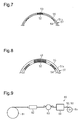
Fig. 7 is a cross-sectional view showing a distal portion of a fiber wound body. -
Fig. 8 is a cross-sectional view showing a basal portion of a fiber wound body. -
Fig. 9 is a schematic diagram of a filament winding device. -
Fig. 10 is a front view of a further example of a tubular braid. -
Fig. 11 is a front view of a further example of a fiber wound body. - A first embodiment of a fiber wound body, a fiber-reinforced resin material, and a method for manufacturing a fiber wound body will now be described with reference to
Figs. 1 to 5 . -
Fig. 1 shows a loadenergy absorbing material 10 used as a fiber-reinforced resin material. The loadenergy absorbing material 10 includes atubular braid 11, which is a fiber wound body used as a fiber-reinforced base, and a matrix resin. - The
tubular braid 11 is shaped as a tubular cone in a structure braided by first reinforcedfiber yarns 12, second reinforcedfiber yarns 13, and third reinforcedfiber yarns 14. Thetubular braid 11 has an axial end including abasal portion 11a and the other axial end including adistal portion 11b. In thetubular braid 11, a direction in which a winding axis L extends refers to the axial direction. - The first reinforced
fiber yarns 12 are arranged parallel to each other. The second reinforcedfiber yarns 13 are arranged parallel to each other and intersect with the first reinforcedfiber yarns 12. The third reinforcedfiber yarns 14 are arranged parallel to each other and intersect with the first reinforcedfiber yarns 12 and the second reinforcedfiber yarns 13. An angle at which the third reinforcedfiber yarns 14 intersect with the first reinforcedfiber yarns 12 is equal to an angle at which the third reinforcedfiber yarns 14 intersect with the second reinforcedfiber yarns 13. The third reinforcedfiber yarns 14 are arranged in a generatrix direction of the cone. Thus, thetubular braid 11 has a structure in which the first reinforcedfiber yarns 12 and the second reinforcedfiber yarns 13 are wound around the third reinforcedfiber yarns 14. The first reinforcedfiber yarns 12 and the second reinforcedfiber yarns 13 are wound about the winding axis L. - The first reinforced
fiber yarns 12 and the second reinforcedfiber yarns 13 are configured to be oblique yarn lines in thetubular braid 11. The third reinforcedfiber yarns 14 are configured to be axial yarn lines in thetubular braid 11. The first reinforcedfiber yarns 12 are arranged to intersect with the winding axis L of thetubular braid 11 at an oblique angle θ. The second reinforcedfiber yarns 13 are arranged to intersect with the winding axis L of thetubular braid 11 at an angle -θ, which is opposite to the oblique angle θ. The oblique angle θ is set in accordance with, for example, the shape of thetubular braid 11 and the required strength. - The first to third reinforced
fiber yarns 12 to 14 are formed by spinning non-continuous fibers. The first to third reinforcedfiber yarns 12 to 14 are formed of carbon fibers, but may be formed of glass fibers or resin fibers. The first to third reinforcedfiber yarns 12 to 14 include gradualcross-section change portions 20, each of which has a cross section that continuously decreases from thebasal portion 11a toward thedistal portion 11b of thetubular braid 11. In the present embodiment, the cross section of the reinforcedfiber yarns 12 to 14 (gradual cross-section change portions 20) refers to the lateral dimension and the transverse dimension of a low-profile cross section of the reinforcedfiber yarns 12 to 14. That is, continuous change in the cross section of a gradualcross-section change portion 20 refers to continuous change in both the lateral dimension and the transverse dimension of the gradualcross-section change portion 20. Alternatively, one of the lateral dimension and the transverse dimension of the gradualcross-section change portion 20 may be fixed while the other dimension continuously changes. - As shown in
Figs. 2 and3 , thetubular braid 11 includes a gradualthickness change portion 18. When the dimension of thetubular braid 11 in the radial direction refers to the thickness, the thickness of the gradualthickness change portion 18 increases toward thebasal portion 11a. That is, the thickness of the gradualthickness change portion 18 decreases toward thedistal portion 11b. Thus, the thickness of thetubular braid 11 gradually decreases from thebasal portion 11a toward thedistal portion 11b along the winding axis L. Each of the reinforcedfiber yarns 12 to 14 has a fiber content rate that is the same at any position in a longitudinal direction of the yarn. Accordingly, thetubular braid 11 has a fiber content rate that is the same at any position in the axial direction. The fiber content rate of each of the reinforcedfiber yarns 12 to 14 refers to the proportion of fibers occupied in the total cross-sectional area of the respective the reinforcedfiber yarns 12 to 14. - The
tubular braid 11 having the configuration described above is manufactured using a braider (braiding device) including a drafting device. - As shown in
Fig. 4 , abraider 30 includes firstoblique yarn feeders 32a and secondoblique yarn feeders 32b. The first reinforcedfiber yarns 12 are fed out of the firstoblique yarn feeders 32a to a circumferential surface of amandrel 31 at a predetermined angle with respect to the axis of themandrel 31. The second reinforcedfiber yarns 13 are fed out of the secondoblique yarn feeders 32b to the circumferential surface of themandrel 31 at a predetermined angle with respect to the axis of themandrel 31. The first reinforcedfiber yarns 12 fed out of the firstoblique yarn feeders 32a are provided to themandrel 31 at an angle +θ. The second reinforcedfiber yarns 13 fed out of the secondoblique yarn feeders 32b are provided to themandrel 31 at an angle -θ. In the present embodiment, the predetermined angle is 45°. Theoblique yarn feeders fiber yarns cross-section change portions 20 and thus have a constant cross section. - The
braider 30 includesaxial yarn feeders 33. The third reinforcedfiber yarns 14 are fed out of theaxial yarn feeders 33 and arranged in the axial direction of themandrel 31. Theaxial yarn feeders 33 feed out the third reinforcedfiber yarns 14 that do not have the gradualcross-section change portions 20 and thus have a constant cross section. - The
braider 30 includes draftingdevices 40. Thedrafting devices 40 are arranged at a downstream side of thefeeders oblique yarn feeders axial yarn feeders 33 feed the reinforcedfiber yarns 12 to 14. Thedrafting devices 40 respectively receive the reinforcedfiber yarns 12 to 14 from thefeeders fiber yarns 12 to 14. - As shown in
Fig. 5 , each of thedrafting devices 40 includes afront roller group 42 and aback roller group 43. Thefront roller group 42 includesrollers 42a. Theback roller group 43 includesrollers 43a. When the reinforcedfiber yarns 12 to 14 are fed out of theoblique yarn feeders axial yarn feeders 33 to themandrel 31, while the circumferential speed of theback roller group 43 is kept constant, the circumferential speed of thefront roller group 42 is continuously increased. Consequently, the cross section of the reinforcedfiber yarns 12 to 14 that have passed through thefront roller group 42 gradually decreases from the cross section at a point in time when the reinforcedfiber yarns 12 to 14 passed through theback roller group 43. - The reinforced
fiber yarns 12 to 14 are elongated so that the cross section of the reinforcedfiber yarns 12 to 14 gradually decreases toward the downstream side in the feeding direction. As a result, each of the reinforcedfiber yarns 12 to 14 has a cross section that gradually decreases and includes the gradualcross-section change portion 20. Additionally, the drafting rate is lower toward the upstream side in the feeding direction. Thus, the cross section of the reinforcedfiber yarns 12 to 14 remains close to the cross section of the reinforcedfiber yarns 12 to 14 that have not been elongated. - When the reinforced
fiber yarns 12 to 14 are fed out of thedrafting devices 40 to themandrel 31, thetubular braid 11 is obtained. The obtainedtubular braid 11 is impregnated with a thermosetting resin and cured to manufacture the loadenergy absorbing material 10. The impregnation and curing of the resin is performed through resin transfer molding (RTM) but may be performed through a process other than resin transfer molding (RTM). - As shown in
Fig. 1 , in the loadenergy absorbing material 10 in which thetubular braid 11 is used as the fiber-reinforced base, as described above, the thickness of thetubular braid 11 gradually increases from thedistal portion 11b toward thebasal portion 11a in the axial direction because of the gradualthickness change portion 18. The strength of the loadenergy absorbing material 10 is lowest in the distal portion, which corresponds to thedistal portion 11b of thetubular braid 11. The strength of the loadenergy absorbing material 10 gradually increases from thedistal portion 11b toward thebasal portion 11a in the axial direction of thetubular braid 11. - The embodiment has the operation and advantages described below.
- (1) In the
tubular braid 11 of the loadenergy absorbing material 10, the first to third reinforcedfiber yarns 12 to 14 include the gradualcross-section change portions 20. The gradualcross-section change portions 20 gradually change the cross section of the first to third reinforcedfiber yarns 12 to 14 so that the strength of thetubular braid 11 gradually varies along the winding axis L. Thetubular braid 11 includes the gradualthickness change portion 18, the thickness of which gradually changes in accordance with the gradualcross-section change portions 20. The thickness of the gradualthickness change portion 18 of thetubular braid 11 gradually changes in accordance with changes in the cross section of the first to third reinforcedfiber yarns 12 to 14. This allows the gradualthickness change portion 18 to have the same fiber content rate at any position in the axial direction of thetubular braid 11. Thus, even when the thickness of thetubular braid 11 is changed, the weight reduction may be achieved as compared to, for example, when further reinforced fibers are added to the first to third reinforcedfiber yarns 12 to 14 to increase the thickness or reinforced fibers are removed from the first to third reinforcedfiber yarns 12 to 14 to decrease the thickness so that the strength of thetubular braid 11 varies. - (2) For example, when first to third reinforced fiber yarns have a uniform cross section and are used to manufacture a tubular braid, the oblique angle θ of the first and second reinforced fiber yarns needs to be controlled to vary the strength in the axial direction of the tubular braid. Such control is complex. Additionally, the design of the oblique angle θ will be complex to achieve the weight reduction. In this regard, in the
tubular braid 11 of the embodiment, the thickness is smoothly and gradually changed in accordance with the gradualcross-section change portions 20. More specifically, the cross section of the first to third reinforcedfiber yarns 12 to 14 is increased on a thick portion of thetubular braid 11, and the cross section of the first to third reinforcedfiber yarns 12 to 14 is decreased on a thin portion of thetubular braid 11. This allows the strength of thetubular braid 11 to vary in the axial direction without changing the oblique angle θ of the first and second reinforcedfiber yarns tubular braid 11 is manufactured without a complex control of the oblique angle θ. - (3) The cross section of the gradual
cross-section change portions 20 of the first to third reinforcedfiber yarns 12 to 14 is smoothly changed and is not abruptly changed such as in a stepped manner. Accordingly, the thickness of thetubular braid 11 is smoothly changed, and the strength is smoothly changed. - (4) In the
tubular braid 11, the oblique angle θ of the first and second reinforcedfiber yarns basal portion 11a to thedistal portion 11b. For example, when thetubular braid 11 is manufactured so that first to third reinforced fiber yarns have a uniform cross section and have a constant oblique angle at the distal portion and the basal portion of the tubular braid, the length of the first and second reinforced fiber yarns extending around the tubular braid once increases at positions toward the basal portion of the tubular braid where the diameter increases. This increases a gap between adjacent ones of the first reinforced fiber yarns and a gap between adjacent ones of the second reinforced fiber yarns. Consequently, the strength of the load energy absorbing material is lowered toward the basal portion of the tubular braid. In this case, to maintain the strength of the basal portion, the oblique angle of the first reinforced fiber yarns and the second reinforced fiber yarns needs to be gradually changed toward the basal portion so that the gap of adjacent ones of the first reinforced fiber yarns and the gap of adjacent ones of the second reinforced fiber yarns are maintained. In this regard, the first and second reinforcedfiber yarns cross-section change portions 20. The gap between adjacent ones of the first reinforcedfiber yarns 12 and the gap between adjacent ones of the second reinforcedfiber yarns 13 will not be excessively increased even at thebasal portion 11a having a large diameter, and the strength will not be lowered. This eliminates the need for a change in the oblique angle of the first and second reinforcedfiber yarns tubular braid 11 to be easily manufactured without lowering the strength. - (5) In the
tubular braid 11, each of the first to third reinforcedfiber yarns 12 to 14 includes the gradualcross-section change portion 20. The strength is easily adjusted at any position in the axial direction of thetubular braid 11 by controlling the cross section of each of the first to third reinforcedfiber yarns 12 to 14. - (6) The
braider 30 manufacturing thetubular braid 11 includes thedrafting devices 40 at the downstream side of theoblique yarn feeders axial yarn feeders 33 in the feeding direction. The cross section is gradually changed with thedrafting devices 40 by controlling the drafting rate of each of the reinforcedfiber yarns 12 to 14 fed out of theoblique yarn feeders axial yarn feeders 33. When the drafting rate is controlled by thedrafting devices 40, thetubular braid 11 having a target thickness is manufactured. - A second embodiment of a fiber wound body, a fiber-reinforced resin material, and a method for manufacturing a fiber wound body will now be described with reference to
Figs. 6 to 9 . In the second embodiment, the same reference characters are given to those elements that are the same as the corresponding elements of the first embodiment. Such elements will not be described in detail. - As shown in
Fig. 6 , a second embodiment of a loadenergy absorbing material 70 used as a fiber-reinforced resin material includes afiber wound body 51, which is used as the fiber-reinforced base, and a matrix resin. - The fiber wound
body 51 is tubular. The fiber woundbody 51 has a structure in which afirst fiber layer 54, which is an inner layer formed by a first reinforcedfiber yarn 52, and asecond fiber layer 55, which is an outer layer formed by a second reinforcedfiber yarn 53 at a radially outer side of thefirst fiber layer 54, are stacked on each other. In the fiber woundbody 51, a direction in which the winding axis L extends refers to the axial direction. The fiber woundbody 51 has an axial end including abasal portion 51a and the other axial end including adistal portion 51b. - The first reinforced
fiber yarn 52 is wound to intersect with the winding axis L of the fiber woundbody 51 at an angle ±θ. The second reinforcedfiber yarn 53 is wound to intersect with the winding axis L of the fiber woundbody 51 at the angle ±θ. The intersecting angle θ of each of the reinforcedfiber yarns body 51 and the required strength. - The first and second reinforced
fiber yarns fiber yarns fiber yarn 52 and the second reinforcedfiber yarn 53 each include a gradualcross-section change portion 56 having a cross section that continuously decreases from thebasal portion 51a toward thedistal portion 51b of the fiber woundbody 51. - As shown in
Fig. 7 and 8 , the fiber woundbody 51 includes a gradualthickness change portion 57. The thickness of the gradualthickness change portion 57 increases toward thebasal portion 51a and decreases toward thedistal portion 51b. Thus, the thickness of the fiber woundbody 51 is gradually decreased by the gradualthickness change portion 57 from thebasal portion 51a toward thedistal portion 51b along the winding axis L. The cross section of the gradualcross-section change portion 56 regularly decreases from a thick part toward a thin part of the gradualthickness change portion 57. Even when the thickness of the fiber woundbody 51 is changed, the gradualthickness change portion 57 is formed by the gradualcross-section change portions 56 of the reinforcedfiber yarns fiber yarns body 51 has a fiber content rate that is the same at any position in the axial direction. - The fiber wound
body 51 is tapered so that the outer diameter gradually decreases from thebasal portion 51a toward thedistal portion 51b. The inner diameter of the fiber woundbody 51 is constant from thebasal portion 51a toward thedistal portion 51b. - The fiber wound
body 51 is manufactured through filament winding. As shown inFig. 9 , afilament winding device 60 manufacturing the fiber woundbody 51 includes amandrel 61, a feedinghead 62, aresin bath 63, adrafting device 64, and abobbin 65. In the same manner as the first embodiment, the draftingdevice 64 includes a front roller and a back roller. The reinforcedfiber yarns cross-section change portion 56 and thus have a constant cross section are wound around thebobbin 65. - When fed out of the
bobbin 65, the reinforcedfiber yarns device 64. As the reinforcedfiber yarns bobbin 65 toward the downstream side in the feeding direction, the reinforcedfiber yarns fiber yarns cross-section change portion 56 is manufactured. - The reinforced
fiber yarns cross-section change portions 56 are impregnated with a resin in theresin bath 63 and then directed to the feedinghead 62. The reinforcedfiber yarns resin bath 63 are wound around amandrel 61 via the feedinghead 62. At this time, angles at which the reinforcedfiber yarns mandrel 61 are adjusted. - The beginning of winding in the fiber wound
body 51 corresponds to thebasal portion 51a. As the reinforcedfiber yarns device 64 so that the cross section gradually decreases, the reinforcedfiber yarns mandrel 61. When the winding is completed, the gradualcross-section change portion 56 is manufactured. The drafting rate of the reinforcedfiber yarns fiber yarns fiber yarns - As shown in
Fig. 6 , in the loadenergy absorbing material 70 in which the fiber woundbody 51 is used as the fiber-reinforced base, as described above, the thickness of the fiber woundbody 51 gradually increases from thedistal portion 51b toward thebasal portion 51a in the axial direction because of the gradualthickness change portion 57. Thus, the strength of the loadenergy absorbing material 70 is lowest in a distal portion corresponding to thedistal portion 51b of the fiber woundbody 51. The strength of the loadenergy absorbing material 70 gradually increases from thedistal portion 51b toward thebasal portion 51a in the axial direction of the fiber woundbody 51. - The second embodiment has the advantages described below in addition to the advantages of the first embodiment.
- (7) In the fiber wound
body 51 of the loadenergy absorbing material 70, the first and second reinforcedfiber yarns cross-section change portions 56. The fiber woundbody 51 includes the gradualthickness change portion 57, the thickness of which gradually changes in accordance with the gradualcross-section change portions 56. The thickness of the gradualthickness change portion 57 of the fiber woundbody 51 gradually changes in accordance with changes in the cross section of the first and second reinforcedfiber yarns body 51. Thus, even when the thickness of the fiber woundbody 51 is changed to vary the strength of the fiber woundbody 51, weight reduction may be achieved. - (8) The fiber wound
body 51 is manufactured through filament winding. For example, when a yarn having a uniform cross section is used in filament winding to manufacture a fiber wound body, a fiber layer for reinforcement needs to be added to a portion that needs higher strength to vary the strength of the fiber woundbody 51 in the axial direction. In this case, the weight will be increased by an amount corresponding to the added fiber layer for reinforcement. In this regard, the cross section of each of the reinforcedfiber yarns basal portion 51a of the fiber woundbody 51. This increases the strength of thebasal portion 51a and eliminates the need for reinforcement of thebasal portion 51a. Thus, the loadenergy absorbing material 70 is easily manufactured without increasing the weight. - (9) In the fiber wound
body 51, two kinds of the reinforcedfiber yarns cross-section change portion 56. Thus, the strength of the fiber woundbody 51 is easily adjusted at any position in the axial direction by controlling the cross section of the first and second reinforcedfiber yarns - (10) The
filament winding device 60 manufacturing the fiber woundbody 51 includes thedrafting device 64 at the downstream side of the feedinghead 62 in the feeding direction. The cross section of each of the reinforcedfiber yarns head 62 is gradually changed with the draftingdevice 64. The fiber woundbody 51 may be manufactured while changing the cross section of each of the reinforcedfiber yarns fiber yarns resin bath 63, the reinforcedfiber yarns device 64. Thus, the reinforcedfiber yarns - The present embodiment may be modified as follows.
- As shown in
Fig. 10 , thetubular braid 11 may be tubular and have a constant diameter in the axial direction. - As shown in
Fig. 11 , the fiber woundbody 51 may be shaped as a tubular cone. - In the
tubular braid 11 of the first embodiment, the first reinforcedfiber yarns 12 and the second reinforcedfiber yarns 13, or the oblique yarn lines, do not need to include the gradualcross-section change portions 20. More specifically, in thetubular braid 11, only the third reinforcedfiber yarns 14, or the axial yarn lines, may include the gradualcross-section change portions 20. Alternatively, when at least one of the first reinforcedfiber yarns 12 and the second reinforcedfiber yarns 13, or the oblique yarn lines, includes the gradualcross-section change portions 20, and the third reinforcedfiber yarns 14, or the axial yarn lines, do not have to include the gradualcross-section change portions 20. More specifically, reinforced fiber yarns including the gradualcross-section change portions 20 may be selected from the first to third reinforcedfiber yarns 12 to 14 to control the thickness of thetubular braid 11. - In the second embodiment, the number of stacked fiber layers may be three or more.
- The fiber-reinforced resin material using the
tubular braid 11 and the fiber woundbody 51 may be used as a structural material instead of a load energy absorbing material. Additionally, thetubular braid 11 and the fiber woundbody 51 may be used in a fiber-reinforced compound including a matrix material other than a matrix resin. - In the
drafting devices - The fiber wound body may be manufactured in a solid structure, instead of a tubular structure, using a three-dimensional braider (three-dimensional braiding device).
- The thickness of the
tubular braid 11 or the fiber woundbody 51 may be constant from thebasal portions distal portions
Claims (5)
- A fiber wound body comprising:reinforced fiber yarns wound about a winding axis, whereineach of the reinforced fiber yarns includes a gradual cross-section change portion, andthe gradual cross-section change portion has a fiber content rate that is constant in a longitudinal direction of the yarn and has a cross section that gradually changes.
- The fiber wound body according to claim 1, further comprising a gradual thickness change portion having a thickness that gradually changes along the winding axis, wherein
the thickness is a dimension of the fiber wound body in a radial direction,
the gradual thickness change portion has a thick part and a thin part, and
the cross section of the gradual cross-section change portion regularly decreases from the thick part toward the thin part of the gradual thickness change portion. - The fiber wound body according to claim 1 or 2, wherein
the reinforced fiber yarns include first reinforced fiber yarns, second reinforced fiber yarns, and third reinforced fiber yarns,
the fiber wound body includes a braid,
the first reinforced fiber yarns are arranged parallel to each other,
the second reinforced fiber yarns are arranged parallel to each other and intersect with the first reinforced fiber yarns,
the third reinforced fiber yarns are arranged parallel to each other and intersect with the first and second reinforced fiber yarns, and
an angle at which the third reinforced fiber yarns intersect with the first reinforced fiber yarns is equal to an angle at which the third reinforced fiber yarns intersect with the second reinforced fiber yarns. - A fiber-reinforced resin material, comprising:the fiber wound body according to any one of claims 1 to 3, the fiber wound body being a fiber-reinforced base; anda matrix resin.
- A method for manufacturing a fiber wound body, the method comprising:elongating each of reinforced fiber yarns having a cross section constant in a longitudinal direction of the yarn in one direction with a drafting device including roller groups;when elongating the reinforced fiber yarns in one direction, forming a gradual cross-section change portion having a fiber content rate that is constant in the longitudinal direction of the yarn and having a cross section that gradually changes by continuously varying a drafting rate of the drafting device to continuously change the cross section of the reinforced fiber yarns in the one direction; andobtaining a fiber wound body by winding the reinforced fiber yarns including the gradual cross-section change portions about a winding axis.
Applications Claiming Priority (2)
| Application Number | Priority Date | Filing Date | Title |
|---|---|---|---|
| JP2016140681A JP6638587B2 (en) | 2016-07-15 | 2016-07-15 | Fiber wound body, fiber reinforced resin material, and method of manufacturing fiber wound body |
| PCT/JP2017/022788 WO2018012225A1 (en) | 2016-07-15 | 2017-06-21 | Fiber wound body, fiber-reinforced resin material, and method for manufacturing fiber wound body |
Publications (3)
| Publication Number | Publication Date |
|---|---|
| EP3486075A1 true EP3486075A1 (en) | 2019-05-22 |
| EP3486075A4 EP3486075A4 (en) | 2019-09-11 |
| EP3486075B1 EP3486075B1 (en) | 2021-03-31 |
Family
ID=60952996
Family Applications (1)
| Application Number | Title | Priority Date | Filing Date |
|---|---|---|---|
| EP17827355.3A Active EP3486075B1 (en) | 2016-07-15 | 2017-06-21 | Fiber wound body, fiber-reinforced resin material, and method for manufacturing fiber wound body |
Country Status (5)
| Country | Link |
|---|---|
| US (1) | US10767022B2 (en) |
| EP (1) | EP3486075B1 (en) |
| JP (1) | JP6638587B2 (en) |
| CN (1) | CN109414889B (en) |
| WO (1) | WO2018012225A1 (en) |
Cited By (1)
| Publication number | Priority date | Publication date | Assignee | Title |
|---|---|---|---|---|
| FR3096694A1 (en) * | 2019-05-28 | 2020-12-04 | Airbus Operations | DEVICE FOR CUTTING A BAND OF FIBERS ACCORDING TO AN EVOLVING WIDTH |
Family Cites Families (11)
| Publication number | Priority date | Publication date | Assignee | Title |
|---|---|---|---|---|
| US4790898A (en) * | 1982-07-19 | 1988-12-13 | The Boeing Company | Method and apparatus for fiber lamination |
| SE511108C2 (en) * | 1997-12-16 | 1999-08-09 | Eng Tex Ab | Method of forming preforms in the manufacture of fiber composites |
| US20030186038A1 (en) * | 1999-11-18 | 2003-10-02 | Ashton Larry J. | Multi orientation composite material impregnated with non-liquid resin |
| JP2005219328A (en) | 2004-02-05 | 2005-08-18 | Murata Mach Ltd | FRP shaft and manufacturing method thereof |
| EP2418412B1 (en) * | 2009-04-10 | 2015-05-27 | Toyota Jidosha Kabushiki Kaisha | Tank and fabrication method thereof |
| DE102011002840A1 (en) * | 2011-01-18 | 2012-07-19 | Sgl Carbon Se | Fiber-reinforced composite component and method for producing a fiber-reinforced composite component |
| FR2974751B1 (en) * | 2011-05-06 | 2013-06-14 | Roxel France | NOVEL THERMAL PROTECTIONS OBTAINED BY FILAMENT WINDING PROCESS AND USE THEREOF |
| US8859088B2 (en) * | 2012-04-16 | 2014-10-14 | Auburn University | Minimal weight composites using open structure |
| JP6079100B2 (en) * | 2012-09-27 | 2017-02-15 | 株式会社豊田自動織機 | Reinforced fiber fabric substrate, reinforced fiber preform and reinforced fiber composite |
| JP2015030959A (en) * | 2013-08-07 | 2015-02-16 | 株式会社豊田自動織機 | Woven fabric, and fiber bundle and fiber-reinforced composite material for composing woven fabric |
| JP2020032629A (en) * | 2018-08-30 | 2020-03-05 | マツダ株式会社 | Component made of fiber reinforced resin |
-
2016
- 2016-07-15 JP JP2016140681A patent/JP6638587B2/en active Active
-
2017
- 2017-06-21 WO PCT/JP2017/022788 patent/WO2018012225A1/en not_active Ceased
- 2017-06-21 CN CN201780042210.9A patent/CN109414889B/en active Active
- 2017-06-21 US US16/316,229 patent/US10767022B2/en active Active
- 2017-06-21 EP EP17827355.3A patent/EP3486075B1/en active Active
Cited By (1)
| Publication number | Priority date | Publication date | Assignee | Title |
|---|---|---|---|---|
| FR3096694A1 (en) * | 2019-05-28 | 2020-12-04 | Airbus Operations | DEVICE FOR CUTTING A BAND OF FIBERS ACCORDING TO AN EVOLVING WIDTH |
Also Published As
| Publication number | Publication date |
|---|---|
| US20190300668A1 (en) | 2019-10-03 |
| JP2018009265A (en) | 2018-01-18 |
| EP3486075B1 (en) | 2021-03-31 |
| CN109414889A (en) | 2019-03-01 |
| US10767022B2 (en) | 2020-09-08 |
| JP6638587B2 (en) | 2020-01-29 |
| CN109414889B (en) | 2021-06-29 |
| EP3486075A4 (en) | 2019-09-11 |
| WO2018012225A1 (en) | 2018-01-18 |
Similar Documents
| Publication | Publication Date | Title |
|---|---|---|
| US9518342B2 (en) | Method of producing a tubular fiber arrangement of a fiber-reinforced composite part, and tubular fiber arrangement | |
| US10232548B2 (en) | Manufacturing method of tank | |
| EP0516673B1 (en) | Fibre reinforced composites | |
| AT514088B1 (en) | Steering column for a motor vehicle and method for producing a steering column | |
| EP2722145B1 (en) | Method and device for manufacturing a dry textile preform | |
| US8114793B2 (en) | Three-dimensional textile component structure consisting of high-tensile threads and method for producing said structure | |
| DE102008014380B4 (en) | Apparatus and method for winding a fiber material on a winding core in the manufacture of a fiber composite component | |
| EP2247435B1 (en) | Method and device and the use thereof for producing a fiber composite part | |
| DE102010047193A1 (en) | Circular braiding machine for processing coal and glass fiber roving for use in manufacture of semi-finished fiber, has control unit that adjusts inner diameter of braiding element corresponding to inner diameter of winded braiding core | |
| DE102014016832B3 (en) | Braiding device and braiding method for braiding a braided core | |
| EP3486075B1 (en) | Fiber wound body, fiber-reinforced resin material, and method for manufacturing fiber wound body | |
| EP4004263B1 (en) | Braiding, winding or spiralling machine, and method for operating same | |
| DE102017219380B4 (en) | Method for producing a pressure vessel | |
| CN110832128B (en) | Method for manufacturing a braided preform, fibre-reinforced component and braiding machine | |
| DE102021113831B4 (en) | Process for producing endless belts using additive manufacturing processes | |
| DE102011106865A1 (en) | Continuous production method for producing fiber-reinforced plastic profiles of any cross-sectional shape using web technology, involves forming a hollow textile structure and preparing the end section of hollow textile structure | |
| JP5910268B2 (en) | Fiber structure, fiber reinforced composite material, method for manufacturing fiber structure, and method for manufacturing fiber reinforced composite material | |
| JP2002011799A (en) | Manufacturing method of fiber reinforced plastic column | |
| DE102017210815B4 (en) | Method for producing a multi-layer fiber composite preform for a fiber composite component | |
| DE102017208946A1 (en) | Shaping tool, apparatus and method |
Legal Events
| Date | Code | Title | Description |
|---|---|---|---|
| STAA | Information on the status of an ep patent application or granted ep patent |
Free format text: STATUS: THE INTERNATIONAL PUBLICATION HAS BEEN MADE |
|
| PUAI | Public reference made under article 153(3) epc to a published international application that has entered the european phase |
Free format text: ORIGINAL CODE: 0009012 |
|
| STAA | Information on the status of an ep patent application or granted ep patent |
Free format text: STATUS: REQUEST FOR EXAMINATION WAS MADE |
|
| 17P | Request for examination filed |
Effective date: 20190103 |
|
| AK | Designated contracting states |
Kind code of ref document: A1 Designated state(s): AL AT BE BG CH CY CZ DE DK EE ES FI FR GB GR HR HU IE IS IT LI LT LU LV MC MK MT NL NO PL PT RO RS SE SI SK SM TR |
|
| AX | Request for extension of the european patent |
Extension state: BA ME |
|
| A4 | Supplementary search report drawn up and despatched |
Effective date: 20190812 |
|
| RIC1 | Information provided on ipc code assigned before grant |
Ipc: B29C 70/32 20060101AFI20190806BHEP Ipc: B29K 105/08 20060101ALI20190806BHEP Ipc: B29L 23/00 20060101ALI20190806BHEP Ipc: B29C 70/24 20060101ALI20190806BHEP Ipc: B29K 105/06 20060101ALI20190806BHEP Ipc: D04C 1/06 20060101ALI20190806BHEP |
|
| DAV | Request for validation of the european patent (deleted) | ||
| DAX | Request for extension of the european patent (deleted) | ||
| GRAP | Despatch of communication of intention to grant a patent |
Free format text: ORIGINAL CODE: EPIDOSNIGR1 |
|
| STAA | Information on the status of an ep patent application or granted ep patent |
Free format text: STATUS: GRANT OF PATENT IS INTENDED |
|
| INTG | Intention to grant announced |
Effective date: 20201223 |
|
| RIN1 | Information on inventor provided before grant (corrected) |
Inventor name: TSUJI, RYOHEI Inventor name: KAMIYA, RYUTA Inventor name: KUNO, SHUN Inventor name: YOSHIKAWA, GENKI |
|
| GRAS | Grant fee paid |
Free format text: ORIGINAL CODE: EPIDOSNIGR3 |
|
| GRAA | (expected) grant |
Free format text: ORIGINAL CODE: 0009210 |
|
| STAA | Information on the status of an ep patent application or granted ep patent |
Free format text: STATUS: THE PATENT HAS BEEN GRANTED |
|
| AK | Designated contracting states |
Kind code of ref document: B1 Designated state(s): AL AT BE BG CH CY CZ DE DK EE ES FI FR GB GR HR HU IE IS IT LI LT LU LV MC MK MT NL NO PL PT RO RS SE SI SK SM TR |
|
| REG | Reference to a national code |
Ref country code: GB Ref legal event code: FG4D Ref country code: CH Ref legal event code: EP |
|
| REG | Reference to a national code |
Ref country code: AT Ref legal event code: REF Ref document number: 1376455 Country of ref document: AT Kind code of ref document: T Effective date: 20210415 |
|
| REG | Reference to a national code |
Ref country code: DE Ref legal event code: R096 Ref document number: 602017035892 Country of ref document: DE |
|
| REG | Reference to a national code |
Ref country code: IE Ref legal event code: FG4D |
|
| REG | Reference to a national code |
Ref country code: LT Ref legal event code: MG9D |
|
| PG25 | Lapsed in a contracting state [announced via postgrant information from national office to epo] |
Ref country code: BG Free format text: LAPSE BECAUSE OF FAILURE TO SUBMIT A TRANSLATION OF THE DESCRIPTION OR TO PAY THE FEE WITHIN THE PRESCRIBED TIME-LIMIT Effective date: 20210630 Ref country code: NO Free format text: LAPSE BECAUSE OF FAILURE TO SUBMIT A TRANSLATION OF THE DESCRIPTION OR TO PAY THE FEE WITHIN THE PRESCRIBED TIME-LIMIT Effective date: 20210630 Ref country code: FI Free format text: LAPSE BECAUSE OF FAILURE TO SUBMIT A TRANSLATION OF THE DESCRIPTION OR TO PAY THE FEE WITHIN THE PRESCRIBED TIME-LIMIT Effective date: 20210331 Ref country code: HR Free format text: LAPSE BECAUSE OF FAILURE TO SUBMIT A TRANSLATION OF THE DESCRIPTION OR TO PAY THE FEE WITHIN THE PRESCRIBED TIME-LIMIT Effective date: 20210331 |
|
| PG25 | Lapsed in a contracting state [announced via postgrant information from national office to epo] |
Ref country code: LV Free format text: LAPSE BECAUSE OF FAILURE TO SUBMIT A TRANSLATION OF THE DESCRIPTION OR TO PAY THE FEE WITHIN THE PRESCRIBED TIME-LIMIT Effective date: 20210331 Ref country code: RS Free format text: LAPSE BECAUSE OF FAILURE TO SUBMIT A TRANSLATION OF THE DESCRIPTION OR TO PAY THE FEE WITHIN THE PRESCRIBED TIME-LIMIT Effective date: 20210331 Ref country code: SE Free format text: LAPSE BECAUSE OF FAILURE TO SUBMIT A TRANSLATION OF THE DESCRIPTION OR TO PAY THE FEE WITHIN THE PRESCRIBED TIME-LIMIT Effective date: 20210331 |
|
| REG | Reference to a national code |
Ref country code: NL Ref legal event code: MP Effective date: 20210331 |
|
| REG | Reference to a national code |
Ref country code: AT Ref legal event code: MK05 Ref document number: 1376455 Country of ref document: AT Kind code of ref document: T Effective date: 20210331 |
|
| PG25 | Lapsed in a contracting state [announced via postgrant information from national office to epo] |
Ref country code: LT Free format text: LAPSE BECAUSE OF FAILURE TO SUBMIT A TRANSLATION OF THE DESCRIPTION OR TO PAY THE FEE WITHIN THE PRESCRIBED TIME-LIMIT Effective date: 20210331 Ref country code: CZ Free format text: LAPSE BECAUSE OF FAILURE TO SUBMIT A TRANSLATION OF THE DESCRIPTION OR TO PAY THE FEE WITHIN THE PRESCRIBED TIME-LIMIT Effective date: 20210331 Ref country code: EE Free format text: LAPSE BECAUSE OF FAILURE TO SUBMIT A TRANSLATION OF THE DESCRIPTION OR TO PAY THE FEE WITHIN THE PRESCRIBED TIME-LIMIT Effective date: 20210331 Ref country code: AT Free format text: LAPSE BECAUSE OF FAILURE TO SUBMIT A TRANSLATION OF THE DESCRIPTION OR TO PAY THE FEE WITHIN THE PRESCRIBED TIME-LIMIT Effective date: 20210331 Ref country code: NL Free format text: LAPSE BECAUSE OF FAILURE TO SUBMIT A TRANSLATION OF THE DESCRIPTION OR TO PAY THE FEE WITHIN THE PRESCRIBED TIME-LIMIT Effective date: 20210331 Ref country code: SM Free format text: LAPSE BECAUSE OF FAILURE TO SUBMIT A TRANSLATION OF THE DESCRIPTION OR TO PAY THE FEE WITHIN THE PRESCRIBED TIME-LIMIT Effective date: 20210331 |
|
| PG25 | Lapsed in a contracting state [announced via postgrant information from national office to epo] |
Ref country code: SK Free format text: LAPSE BECAUSE OF FAILURE TO SUBMIT A TRANSLATION OF THE DESCRIPTION OR TO PAY THE FEE WITHIN THE PRESCRIBED TIME-LIMIT Effective date: 20210331 Ref country code: RO Free format text: LAPSE BECAUSE OF FAILURE TO SUBMIT A TRANSLATION OF THE DESCRIPTION OR TO PAY THE FEE WITHIN THE PRESCRIBED TIME-LIMIT Effective date: 20210331 Ref country code: PL Free format text: LAPSE BECAUSE OF FAILURE TO SUBMIT A TRANSLATION OF THE DESCRIPTION OR TO PAY THE FEE WITHIN THE PRESCRIBED TIME-LIMIT Effective date: 20210331 Ref country code: PT Free format text: LAPSE BECAUSE OF FAILURE TO SUBMIT A TRANSLATION OF THE DESCRIPTION OR TO PAY THE FEE WITHIN THE PRESCRIBED TIME-LIMIT Effective date: 20210802 Ref country code: IS Free format text: LAPSE BECAUSE OF FAILURE TO SUBMIT A TRANSLATION OF THE DESCRIPTION OR TO PAY THE FEE WITHIN THE PRESCRIBED TIME-LIMIT Effective date: 20210731 |
|
| REG | Reference to a national code |
Ref country code: DE Ref legal event code: R097 Ref document number: 602017035892 Country of ref document: DE |
|
| PG25 | Lapsed in a contracting state [announced via postgrant information from national office to epo] |
Ref country code: ES Free format text: LAPSE BECAUSE OF FAILURE TO SUBMIT A TRANSLATION OF THE DESCRIPTION OR TO PAY THE FEE WITHIN THE PRESCRIBED TIME-LIMIT Effective date: 20210331 Ref country code: AL Free format text: LAPSE BECAUSE OF FAILURE TO SUBMIT A TRANSLATION OF THE DESCRIPTION OR TO PAY THE FEE WITHIN THE PRESCRIBED TIME-LIMIT Effective date: 20210331 Ref country code: DK Free format text: LAPSE BECAUSE OF FAILURE TO SUBMIT A TRANSLATION OF THE DESCRIPTION OR TO PAY THE FEE WITHIN THE PRESCRIBED TIME-LIMIT Effective date: 20210331 Ref country code: MC Free format text: LAPSE BECAUSE OF FAILURE TO SUBMIT A TRANSLATION OF THE DESCRIPTION OR TO PAY THE FEE WITHIN THE PRESCRIBED TIME-LIMIT Effective date: 20210331 |
|
| REG | Reference to a national code |
Ref country code: CH Ref legal event code: PL |
|
| PLBE | No opposition filed within time limit |
Free format text: ORIGINAL CODE: 0009261 |
|
| STAA | Information on the status of an ep patent application or granted ep patent |
Free format text: STATUS: NO OPPOSITION FILED WITHIN TIME LIMIT |
|
| 26N | No opposition filed |
Effective date: 20220104 |
|
| REG | Reference to a national code |
Ref country code: BE Ref legal event code: MM Effective date: 20210630 |
|
| PG25 | Lapsed in a contracting state [announced via postgrant information from national office to epo] |
Ref country code: LU Free format text: LAPSE BECAUSE OF NON-PAYMENT OF DUE FEES Effective date: 20210621 |
|
| PG25 | Lapsed in a contracting state [announced via postgrant information from national office to epo] |
Ref country code: LI Free format text: LAPSE BECAUSE OF NON-PAYMENT OF DUE FEES Effective date: 20210630 Ref country code: IE Free format text: LAPSE BECAUSE OF NON-PAYMENT OF DUE FEES Effective date: 20210621 Ref country code: CH Free format text: LAPSE BECAUSE OF NON-PAYMENT OF DUE FEES Effective date: 20210630 |
|
| PG25 | Lapsed in a contracting state [announced via postgrant information from national office to epo] |
Ref country code: IS Free format text: LAPSE BECAUSE OF FAILURE TO SUBMIT A TRANSLATION OF THE DESCRIPTION OR TO PAY THE FEE WITHIN THE PRESCRIBED TIME-LIMIT Effective date: 20210731 |
|
| PG25 | Lapsed in a contracting state [announced via postgrant information from national office to epo] |
Ref country code: BE Free format text: LAPSE BECAUSE OF NON-PAYMENT OF DUE FEES Effective date: 20210630 |
|
| P01 | Opt-out of the competence of the unified patent court (upc) registered |
Effective date: 20230519 |
|
| PG25 | Lapsed in a contracting state [announced via postgrant information from national office to epo] |
Ref country code: CY Free format text: LAPSE BECAUSE OF FAILURE TO SUBMIT A TRANSLATION OF THE DESCRIPTION OR TO PAY THE FEE WITHIN THE PRESCRIBED TIME-LIMIT Effective date: 20210331 |
|
| PG25 | Lapsed in a contracting state [announced via postgrant information from national office to epo] |
Ref country code: HU Free format text: LAPSE BECAUSE OF FAILURE TO SUBMIT A TRANSLATION OF THE DESCRIPTION OR TO PAY THE FEE WITHIN THE PRESCRIBED TIME-LIMIT; INVALID AB INITIO Effective date: 20170621 Ref country code: GR Free format text: LAPSE BECAUSE OF FAILURE TO SUBMIT A TRANSLATION OF THE DESCRIPTION OR TO PAY THE FEE WITHIN THE PRESCRIBED TIME-LIMIT Effective date: 20210331 |
|
| PG25 | Lapsed in a contracting state [announced via postgrant information from national office to epo] |
Ref country code: MK Free format text: LAPSE BECAUSE OF FAILURE TO SUBMIT A TRANSLATION OF THE DESCRIPTION OR TO PAY THE FEE WITHIN THE PRESCRIBED TIME-LIMIT Effective date: 20210331 |
|
| PG25 | Lapsed in a contracting state [announced via postgrant information from national office to epo] |
Ref country code: TR Free format text: LAPSE BECAUSE OF FAILURE TO SUBMIT A TRANSLATION OF THE DESCRIPTION OR TO PAY THE FEE WITHIN THE PRESCRIBED TIME-LIMIT Effective date: 20210331 |
|
| PGFP | Annual fee paid to national office [announced via postgrant information from national office to epo] |
Ref country code: GB Payment date: 20240502 Year of fee payment: 8 |
|
| PGFP | Annual fee paid to national office [announced via postgrant information from national office to epo] |
Ref country code: DE Payment date: 20240502 Year of fee payment: 8 |
|
| PGFP | Annual fee paid to national office [announced via postgrant information from national office to epo] |
Ref country code: IT Payment date: 20240513 Year of fee payment: 8 Ref country code: FR Payment date: 20240509 Year of fee payment: 8 |
|
| PG25 | Lapsed in a contracting state [announced via postgrant information from national office to epo] |
Ref country code: MT Free format text: LAPSE BECAUSE OF FAILURE TO SUBMIT A TRANSLATION OF THE DESCRIPTION OR TO PAY THE FEE WITHIN THE PRESCRIBED TIME-LIMIT Effective date: 20210331 |
|
| REG | Reference to a national code |
Ref country code: DE Ref legal event code: R119 Ref document number: 602017035892 Country of ref document: DE |
|
| GBPC | Gb: european patent ceased through non-payment of renewal fee |
Effective date: 20250621 |
|
| PG25 | Lapsed in a contracting state [announced via postgrant information from national office to epo] |
Ref country code: GB Free format text: LAPSE BECAUSE OF NON-PAYMENT OF DUE FEES Effective date: 20250621 |
|
| PG25 | Lapsed in a contracting state [announced via postgrant information from national office to epo] |
Ref country code: DE Free format text: LAPSE BECAUSE OF NON-PAYMENT OF DUE FEES Effective date: 20260101 |
|
| PG25 | Lapsed in a contracting state [announced via postgrant information from national office to epo] |
Ref country code: IT Free format text: LAPSE BECAUSE OF NON-PAYMENT OF DUE FEES Effective date: 20250621 |
|
| PG25 | Lapsed in a contracting state [announced via postgrant information from national office to epo] |
Ref country code: FR Free format text: LAPSE BECAUSE OF NON-PAYMENT OF DUE FEES Effective date: 20250630 |