EP3486025A1 - Laser machining method, controller, and robot system - Google Patents
Laser machining method, controller, and robot system Download PDFInfo
- Publication number
- EP3486025A1 EP3486025A1 EP18205603.6A EP18205603A EP3486025A1 EP 3486025 A1 EP3486025 A1 EP 3486025A1 EP 18205603 A EP18205603 A EP 18205603A EP 3486025 A1 EP3486025 A1 EP 3486025A1
- Authority
- EP
- European Patent Office
- Prior art keywords
- head
- robot
- radiation locus
- controller
- shape
- Prior art date
- Legal status (The legal status is an assumption and is not a legal conclusion. Google has not performed a legal analysis and makes no representation as to the accuracy of the status listed.)
- Granted
Links
Images




Classifications
-
- B—PERFORMING OPERATIONS; TRANSPORTING
- B23—MACHINE TOOLS; METAL-WORKING NOT OTHERWISE PROVIDED FOR
- B23K—SOLDERING OR UNSOLDERING; WELDING; CLADDING OR PLATING BY SOLDERING OR WELDING; CUTTING BY APPLYING HEAT LOCALLY, e.g. FLAME CUTTING; WORKING BY LASER BEAM
- B23K26/00—Working by laser beam, e.g. welding, cutting or boring
- B23K26/08—Devices involving relative movement between laser beam and workpiece
- B23K26/0869—Devices involving movement of the laser head in at least one axial direction
- B23K26/0876—Devices involving movement of the laser head in at least one axial direction in at least two axial directions
- B23K26/0884—Devices involving movement of the laser head in at least one axial direction in at least two axial directions in at least three axial directions, e.g. manipulators, robots
-
- B—PERFORMING OPERATIONS; TRANSPORTING
- B23—MACHINE TOOLS; METAL-WORKING NOT OTHERWISE PROVIDED FOR
- B23K—SOLDERING OR UNSOLDERING; WELDING; CLADDING OR PLATING BY SOLDERING OR WELDING; CUTTING BY APPLYING HEAT LOCALLY, e.g. FLAME CUTTING; WORKING BY LASER BEAM
- B23K26/00—Working by laser beam, e.g. welding, cutting or boring
- B23K26/02—Positioning or observing the workpiece, e.g. with respect to the point of impact; Aligning, aiming or focusing the laser beam
- B23K26/04—Automatically aligning, aiming or focusing the laser beam, e.g. using the back-scattered light
- B23K26/042—Automatically aligning the laser beam
- B23K26/043—Automatically aligning the laser beam along the beam path, i.e. alignment of laser beam axis relative to laser beam apparatus
-
- B—PERFORMING OPERATIONS; TRANSPORTING
- B23—MACHINE TOOLS; METAL-WORKING NOT OTHERWISE PROVIDED FOR
- B23K—SOLDERING OR UNSOLDERING; WELDING; CLADDING OR PLATING BY SOLDERING OR WELDING; CUTTING BY APPLYING HEAT LOCALLY, e.g. FLAME CUTTING; WORKING BY LASER BEAM
- B23K26/00—Working by laser beam, e.g. welding, cutting or boring
- B23K26/02—Positioning or observing the workpiece, e.g. with respect to the point of impact; Aligning, aiming or focusing the laser beam
- B23K26/04—Automatically aligning, aiming or focusing the laser beam, e.g. using the back-scattered light
- B23K26/046—Automatically focusing the laser beam
-
- B—PERFORMING OPERATIONS; TRANSPORTING
- B23—MACHINE TOOLS; METAL-WORKING NOT OTHERWISE PROVIDED FOR
- B23K—SOLDERING OR UNSOLDERING; WELDING; CLADDING OR PLATING BY SOLDERING OR WELDING; CUTTING BY APPLYING HEAT LOCALLY, e.g. FLAME CUTTING; WORKING BY LASER BEAM
- B23K26/00—Working by laser beam, e.g. welding, cutting or boring
- B23K26/02—Positioning or observing the workpiece, e.g. with respect to the point of impact; Aligning, aiming or focusing the laser beam
- B23K26/06—Shaping the laser beam, e.g. by masks or multi-focusing
- B23K26/073—Shaping the laser spot
- B23K26/0736—Shaping the laser spot into an oval shape, e.g. elliptic shape
-
- B—PERFORMING OPERATIONS; TRANSPORTING
- B23—MACHINE TOOLS; METAL-WORKING NOT OTHERWISE PROVIDED FOR
- B23K—SOLDERING OR UNSOLDERING; WELDING; CLADDING OR PLATING BY SOLDERING OR WELDING; CUTTING BY APPLYING HEAT LOCALLY, e.g. FLAME CUTTING; WORKING BY LASER BEAM
- B23K26/00—Working by laser beam, e.g. welding, cutting or boring
- B23K26/08—Devices involving relative movement between laser beam and workpiece
- B23K26/082—Scanning systems, i.e. devices involving movement of the laser beam relative to the laser head
-
- B—PERFORMING OPERATIONS; TRANSPORTING
- B25—HAND TOOLS; PORTABLE POWER-DRIVEN TOOLS; MANIPULATORS
- B25J—MANIPULATORS; CHAMBERS PROVIDED WITH MANIPULATION DEVICES
- B25J9/00—Program-controlled manipulators
- B25J9/16—Program controls
- B25J9/1679—Program controls characterised by the tasks executed
Definitions
- the present invention relates to a laser machining method, a controller, and a robot system.
- Some robots known in the art make a motion by driving a plurality of joints.
- Such robot includes an end effector mounted at the leading end of the robot.
- the end effector varies depending on the application in which the robot is used, such as machining and welding, so that the robot is capable of performing various kinds of work such as machining and welding a workpiece.
- JP 2015-150655A discloses, as an end effector, a laser machining head capable of being taught a shape of a radiation locus.
- JP 2015-150655A The contents of JP 2015-150655A are incorporated herein by reference in their entirety.
- the end effector has room for improvement in machining quality in applications where the direction of a machining line relative to a workpiece changes.
- a laser machining method uses a head and a robot.
- the head is configured to variably make a shape of a radiation locus using laser.
- the robot is configured to cause the head to move along a machining line.
- the laser machining method includes obtaining a movement direction in which the head is being moved by the robot.
- the radiation locus made by the head is adjusted to keep a constant relative angle between the movement direction obtained in the obtaining step and a representative angle of the shape of the radiation locus.
- a controller is configured to control a motion of a head that is configured to variably make a shape of a radiation locus using laser.
- the controller includes an obtainer and an adjuster.
- the obtainer is configured to obtain a movement direction in which the head is being moved along a machining line by a robot.
- the adjuster is configured to adjust the radiation locus made by the head to keep a constant relative angle between the movement direction obtained by the obtainer and a representative angle of the shape of the radiation locus.
- a robot system includes a head, a robot, and a controller.
- the head is configured to variably make a shape of a radiation locus using laser.
- the robot is configured to cause the head to move along a machining line.
- the controller is configured to control a motion of the head, and includes an obtainer and an adjuster.
- the obtainer is configured to obtain a movement direction in which the head is being moved by the robot along the machining line.
- the adjuster is configured to adjust the radiation locus made by the head to keep a constant relative angle between the movement direction obtained by the obtainer and a representative angle of the shape of the radiation locus.
- the embodiments of the present invention provide such a laser machining method, a controller, and a robot system that maintain machining quality even in applications where the direction of a machining line relative to a workpiece changes.
- laser machining method and robot system according to embodiments of the present invention will be described in detail below. It is noted that the following embodiments are provided for example purposes only and are not intended for limiting purposes. Also, while in the following description laser welding is taken as an example of laser machining, it is also possible to change the roughness of a workpiece, form a groove on a workpiece, or draw a picture on a workpiece.
- FIG. 1 illustrates an outline of the laser machining method according to this embodiment.
- a head 100 which performs laser machining, is mounted on the leading end of a robot 10.
- the robot 10 moves the head 100 along a machining line 200.
- the machining line 200 is set on the workpiece W.
- the machining line 200 refers to an imaginary line set along the extending direction of a machining area of the workpiece W.
- the head 100 includes a unit of mechanism such as a mirror galvanometer for changing the direction of laser radiation. Specifically, two mirrors swingable about different axes are independently driven to change the direction of laser radiation in a desired manner.
- the head 100 is capable of causing the two mirrors to cooperate with each other to make any desired shape of a radiation locus P.
- the head 100 is also capable of changing a representative direction PV in which the shape of the radiation locus P is pointed.
- the radiation locus P has an ellipse shape, and the representative direction PV is parallel to the longitudinal axis of the ellipse shape. Also in FIG. 1 , movement directions V of the radiation locus P and the head 100 are illustrated at predetermined spatial intervals. It is to be that while the radiation locus P forms a spiral shape in actual situations of the movement of the head 100 along the machining line 200, the radiation locus P is illustrated in the shape of an ellipse for simplicity of description.
- the laser machining method includes adjusting the shape of the radiation locus P to keep a constant relative angle between the representative direction PV of the radiation locus P and the movement direction V of the head 100 moving along the machining line 200.
- the head 100 changes the direction in which the shape of the radiation locus P is pointed to keep a constant relative angle of ⁇ between the movement direction V and the representative direction PV.
- the laser machining method according to this embodiment eliminates or minimizes degradation of machining quality even when the machining line 200 is curved, that is, even when the direction of the machining line 200 changes. That is, the laser machining method according to this embodiment maintains laser machining quality.
- the laser machining method prioritizes the motion of the head 100 to change the representative direction PV of the radiation locus P over the motion of the robot 10 to change the posture of the head 100. This eliminates or minimizes vibration in the robot 10 involved with the change of the posture of the head 100, resulting in increased machining accuracy.
- the laser machining method described above by referring to FIG. 1 can be performed by a robot system 1.
- FIG. 2 description will be made with regard to how the elements of the robot system 1 are connected to each other.
- FIG. 2 illustrates how the elements of the robot system 1 are connected to each other.
- the robot system 1 includes the robot 10, a robot controller 20, a terminal device 30, the head 100, a head controller 110, and a laser oscillator 120.
- FIG. 2 also illustrates the workpiece W, which is an object machined by the robot system 1. It is also to be noted in the following description that a reference to "the controller” indicates the head controller 110, instead of the robot controller 20.
- the robot 10 is a six-axis vertical multi-articular robot with the head 100 mounted on the leading end of the robot.
- the robot controller 20 controls motions of the robot 10.
- the terminal device 30 transmits setting values or other parameters for the head 100 to the head controller 110 in a wired or wireless manner.
- the head controller 110 controls motions of the head 100 based on setting values for the head 100 received through the robot controller 20.
- the head controller 110 also makes instructions such as a laser intensity instruction to the laser oscillator 120.
- the laser oscillator 120 Upon receipt of an instruction from the head controller 110, the laser oscillator 120 transmits laser to the head 100 through an optical fiber 121.
- the elements of the robot system 1 will be described in detail later by referring to FIG. 4 .
- the robot controller 20 may incorporate therein the functions of the head controller 110.
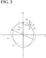
- FIG. 3 illustrates how the head 100 makes a motion. Specifically, FIG. 3 illustrates an xy coordinate system fixed to the head 100.
- FIG. 3 also illustrates a laser radiation point L with swing direction M1 and swing direction M2 of a pair of swingable mirrors.
- the swing direction M1 and the swing direction M2 are orthogonal to each other, the x axis and the swing direction M1 are parallel to each other, and the y axis and the swing direction M2 are parallel to each other.
- the head 100 moves the laser radiation point L in the swing direction M1 and the swing direction M2.
- the locus of motion of the radiation point L that is, the radiation locus P can have any shape.
- the radiation locus P has an ellipse shape, similarly to the radiation locus P illustrated in FIG. 1 , and the representative direction PV of the radiation locus P is parallel to the longitudinal axis of the ellipse shape. Also in FIG. 3 , the representative direction PV matches the y axis.
- the head 100 adjusts the displacement in the swing direction M1 and the displacement in the swing direction M2 in a desired manner to turn the radiation locus P by a desired angle while maintaining the shape of the radiation locus P.
- the radiation locus P is turned counter-clockwise by an angle of ⁇ , resulting in a radiation locus PI as indicated by a broken line.
- the representative direction PV of the radiation locus P is turned by an angle of ⁇ , resulting in a representative direction PV1 as indicated by a broken line arrow.
- the head 100 is able to change the representative direction PV of the radiation locus P by a desired angle without changing the posture of the head 100.
- the head 100 is capable of making any other various shapes than an ellipse for the radiation locus P. This will be described later by referring to FIGs. 6A and 6B .
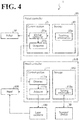
- FIG. 4 is a block diagram illustrating a configuration of the robot system 1.
- the robot system 1 includes the robot 10, the robot controller 20, the terminal device 30, the head 100, the head controller 110, and the laser oscillator 120.
- the terminal device 30 directly communicates with the head controller 110 in FIG. 4 .
- the terminal device 30 may indirectly communicate with the head controller 110 through the robot controller 20.
- the following description is mainly regarding a configuration of the robot controller 20 and a configuration of the head controller 110.
- the robot controller 20 is connected to the robot 10 and the head controller 110.
- the robot controller 20 controls motions of the robot 10 and transmits to the head controller 110 information used in motion control of the head 100.
- the robot controller 20 includes a control section 21 and a storage 22.
- the control section 21 includes a motion controller 21a and an outputter 21b.
- the storage 22 stores teaching information 22a.
- the robot controller 20 includes a computer and various circuits.
- the computer includes a central processing unit (CPU), a read only memory (ROM), a random access memory (RAM), a hard disk drive (HDD), and input-output ports.
- the CPU of the computer reads programs stored in the ROM and executes the programs to serve the functions of the motion controller 21a and the outputter 21b of the control section 21.
- At least one or all of the motion controller 21a and the outputter 21b may be implemented by hardware such as ASIC (Application Specific Integrated Circuit) and FPGA (Field Programmable Gate Array).
- the storage 22 corresponds to the RAM and/or the HDD.
- the RAM and the HDD are capable of storing the teaching information 22a. It will be understood by those skilled in the art that the robot controller 20 may obtain the above-described programs and various kinds of information from another computer connected to the robot controller 20 through a wired or wireless network or from a portable recording medium.
- the motion controller 21a controls the robot 10 to make a motion.
- the teaching information 22a is prepared in the teaching stage, in which the robot 10 is taught a motion, and includes "jobs" that constitute a program defining a motion path of the robot 10.
- the robot system 1 prioritizes the motion of the head 100.
- the teaching information 22a includes a content specifying that the robot 10 does not change the posture of the head 100.
- the motion controller 21a calculates the movement direction V of the head 100 mounted on the robot 10 and calculates the posture of the head 100. In such an application that the movement direction V of the head 100 is represented using a coordinate system fixed to the head 100, the calculation of the posture of the head 100 may be omitted.
- the motion controller 21a performs feedback control using an encoder value from an actuator such as a motor that provides motive power to the robot 10. In this manner, the motion controller 21a improves the motion accuracy of the robot 10.
- the outputter 21b After the motion controller 21a has calculated the movement direction V of the head 100 and the posture of the head 100, the outputter 21b outputs the movement direction V and the posture of the head 100 to the head controller 110.
- the outputter 21b may omit the output of the posture of the head 100.
- the outputter 21b may also omit the output of the posture of the head 100 when the movement direction V of the head 100 is represented on a coordinate system fixed to the head 100.
- the head controller 110 is connected to the head 100, the laser oscillator 120, and the terminal device 30.
- the head controller 110 receives the radiation locus P made by the head 100, the representative direction PV of the radiation locus P, and setting information 112a, which is associated with laser intensity.
- the head controller 110 may be similar to the robot controller 20 in hardware configuration and software configuration.
- the head controller 110 receives the movement direction V of the head 100 and the posture of the head 100. Then, the head controller 110 controls motions of the head 100 based on the setting information 112a and other information received from the terminal device 30 and the robot controller 20.
- the head controller 110 includes a control section 111 and a storage 112.
- the control section 111 includes an obtainer 111a and an adjuster 111b.
- the storage 112 stores the setting information 112a.
- the obtainer 111a receives the movement direction V of the head 100 and the posture of the head 100. Then, the obtainer 111a forwards the received information to the adjuster 111b.
- the adjuster 111b controls motions of the head 100 based on: the movement direction V of the head 100 and the posture of the head 100 received from the obtainer 111a; and the setting information 112a.
- the adjuster 111b adjusts the motion of the head 100 based on the movement direction V of the head 100 received from the robot controller 20. By adjusting the motion of the head 100 in this manner, the adjuster 111b makes a constant angle of ⁇ (see FIG. 1 ) between the movement direction V of the head 100 and the representative direction PV of the radiation locus P.
- the adjuster 111b adjusts the motion of the head 100 based on the posture of the head 100 and the movement direction V of the head 100 received from the robot controller 20. By adjusting the motion of the head 100 in this manner, the adjuster 111b makes a constant angle of ⁇ (see FIG. 1 ) between the movement direction V of the head 100 and the representative direction PV of the radiation locus P.
- the adjuster 111b may adjust the motion of the head 100 to keep a constant angle of ⁇ (see FIG. 1 ) between the movement direction V and the representative direction PV of the radiation locus P. That is, the adjuster 111b is able to adjust the motion of the head 100 without using the posture of the head 100.
- the adjuster 111b Based on the setting information 112a, the adjuster 111b transmits to the laser oscillator 120 a change instruction for change of laser intensity or similar parameter.
- the laser oscillator 120 provides the head 100 with a level of laser corresponding to the change instruction from the adjuster 111b.
- the terminal device 30 is a computer that includes an input-output device, such as a touch panel display, and a wired or wireless communication device.
- the terminal device 30 displays a content of the setting information 112a and an input-output screen on which the content can be corrected or changed and on which new information can be input.
- FIG. 5 illustrates setting items of the head 100.
- FIG. 5 illustrates an XY coordinate system with the X axis matching the movement direction V .
- the XY coordinate system is a coordinate system that is based on the workpiece W, as opposed to the xy coordinate system illustrated in FIG. 3 (coordinate system fixed to the head 100).
- the robot system 1 may perform control using both an xy coordinate system, with the x axis and the y axis, and an XY coordinate system, with the X axis and the Y axis. In this case, the xy coordinate system and the XY coordinate system are the same coordinate systems.
- the head 100's setting items include starting phase s, ending phase e, center c , welding width w, progression length l , inclination angle ⁇ , and specified shape. Based on these setting items, the radiation locus P and its representative direction PV illustrated in FIG. 5 are determined uniquely.
- the specified shape is an ellipse shape.
- the starting phase s is a counter-clockwise angle relative to the X axis.
- the starting phase s is 0° (degrees).
- the ending phase e is a counter-clockwise angle relative to the X axis. In the embodiment of FIG. 5 , the ending phase e is 180° (degrees).
- the starting phase s corresponds to the angle at which laser radiation starts
- the ending phase e corresponds to the angle at which laser radiation stops.
- the center c corresponds to the center of the shape of the radiation locus P.
- the welding width w corresponds to the width of the shape in the representative direction PV.
- the progression length l corresponds to the width of the shape in a direction perpendicular to the representative direction PV.
- the inclination angle ⁇ corresponds to the angle ⁇ illustrated in FIG. 1 . It is also possible to use the turning direction of the radiation locus P as an additional setting item. In this case, a choice can be made as to whether the radiation locus P turns clockwise or counter-clockwise.
- the setting items illustrated in FIG. 5 may be input through the terminal device 30 illustrated in FIG. 4 . While in FIG. 5 the shape of the radiation locus P is an ellipse, the head 100 is capable of making any other various shapes than an ellipse for the radiation locus P.
- FIGs. 6A and 6B variations of the shape of the radiation locus P will be described below.
- FIGs. 6A and 6B respectively illustrate a first variation and a second variation of the shape of the radiation locus P. Specifically, FIG. 6A illustrates a figure-of-eight shape, and FIG. 6B illustrates a rectangular shape.
- the head 100 is capable of making, as radiation locus Pa, a shape of two circles connected together.
- the shape may have a representative angle VP parallel to the longitudinal axis of the radiation locus Pa.
- the representative angle VP may also be parallel to the shorter axis of the radiation locus Pa, or may be different from the longitudinal axis or the shorter axis by a predetermined angle.
- the head 100 is capable of making, as radiation locus Pb, a rectangular shape.
- the representative direction PV may be parallel to the longitudinal sides of the radiation locus Pb.
- the representative angle VP may also be parallel to shorter sides of the radiation locus Pb, or may be different from the longitudinal sides or the shorter sides by a predetermined angle.
- the shape of the radiation locus P may be a triangle or a linear shape. That is, the shape of the radiation locus P may be any shape that can be drawn unicursally.
- the laser radiation point L (see FIG. 3 ) makes a reciprocating motion between one end and the other end of the linear shape.
- FIG. 7 is a flowchart of a procedure for processing performed by the robot system 1.
- the head controller 110 receives, through the terminal device 30, a setting of the relative angle between the movement direction V and the representative direction PV (step S101).
- the head controller 110 also receives, through the terminal device 30, a choice of the shape of the radiation locus P (step S102).
- the contents received at steps S101 and S102 are reflected in the setting information 112a. Steps S101 and S102 correspond to the setting step recited in the appended claims.
- the head controller 110 communicates with the robot controller 20 to determine whether machining has started (step S103).
- the obtainer 111a obtains the movement direction V of the head 100 (step S104).
- the determination processing at step S103 is repeated at predetermined time intervals.
- the adjuster 111b updates the representative direction PV of the radiation locus P made by the head 100 (step S105). This configuration keeps the relative angle between the movement direction V and the representative direction PV constant even when the machining line 200 is curved.
- step S106 the head controller 110 communicates with the robot controller 20 to determine whether machining has ended.
- the entire processing ends.
- the condition at step S106 is not satisfied (No at step S106)
- the procedure at and after step S104 is repeated.
- the laser machining method uses the head 100 and the robot 10.
- the head 100 is capable of variably making the shape of the laser radiation locus P.
- the robot 10 causes the head 100 to move along the machining line 200.
- the laser machining method includes an obtaining step and an adjusting step.
- the obtaining step includes obtaining the movement direction V , in which the head 100 is being moved by the robot 10 along the machining line 200.
- the adjusting step includes adjusting the radiation locus P made by the head 100 to keep a constant relative angle between the movement direction V obtained in the obtaining step and the representative direction PV of the shape of the radiation locus P.
- the laser machining method keeps the representative direction PV of the shape of the radiation locus P constant relative to the movement direction V of the head 100. This configuration maintains machining quality even when the direction of the machining line 200 changes relative to the workpiece W.
- the head controller 110 controls motions of the head 100, which is capable of variably making the shape of the laser radiation locus P.
- the head controller 110 includes the obtainer 111a and the adjuster 111b.
- the obtainer 111a obtains the movement direction V , in which the head 100 is being moved by the robot 10 along the machining line 200.
- the adjuster 111b adjusts the radiation locus P, which is made by the head 100, to keep a constant relative angle between the movement direction V obtained by the obtainer 111a and the representative direction PV of the shape of the radiation locus P.
- the head controller 110 keeps the representative direction PV of the shape of the radiation locus P constant relative to the movement direction V of the head 100. This configuration maintains machining quality even when the direction of the machining line 200 changes relative to the workpiece W.
- the robot system 1 includes the head 100, the robot 10, and the head controller 110.
- the head 100 is capable of variably making the shape of the laser radiation locus P.
- the robot 10 causes the head 100 to move along the machining line 200.
- the head controller 110 is a controller that controls motions of the head 100.
- the head controller 110 includes the obtainer 111a and the adjuster 111b.
- the obtainer 111a obtains the movement direction V , in which the head 100 is being moved by the robot 10 along the machining line 200.
- the adjuster 111b adjusts the radiation locus P, which is made by the head 100, to keep a constant relative angle between the movement direction V obtained by the obtainer 111a and the representative direction PV of the shape of the radiation locus P.
- the robot system 1 keeps the representative direction PV of the shape of the radiation locus P constant relative to the movement direction V of the head 100. This configuration maintains machining quality even when the direction of the machining line 200 changes relative to the workpiece W.
Landscapes
- Physics & Mathematics (AREA)
- Optics & Photonics (AREA)
- Engineering & Computer Science (AREA)
- Mechanical Engineering (AREA)
- Plasma & Fusion (AREA)
- Robotics (AREA)
- Laser Beam Processing (AREA)
- Manipulator (AREA)
Abstract
Description
- The present invention relates to a laser machining method, a controller, and a robot system.
- Some robots known in the art make a motion by driving a plurality of joints. Such robot includes an end effector mounted at the leading end of the robot. The end effector varies depending on the application in which the robot is used, such as machining and welding, so that the robot is capable of performing various kinds of work such as machining and welding a workpiece.
-
JP 2015-150655A - The contents of
JP 2015-150655A - The end effector, however, has room for improvement in machining quality in applications where the direction of a machining line relative to a workpiece changes.
- It is an object of an embodiment of the present invention to provide such a laser machining method, a controller, and a robot system that maintain machining quality even in applications where the direction of a machining line relative to a workpiece changes.
- According to one aspect of the present invention, a laser machining method uses a head and a robot. The head is configured to variably make a shape of a radiation locus using laser. The robot is configured to cause the head to move along a machining line. The laser machining method includes obtaining a movement direction in which the head is being moved by the robot. The radiation locus made by the head is adjusted to keep a constant relative angle between the movement direction obtained in the obtaining step and a representative angle of the shape of the radiation locus.
- According to another aspect of the present invention, a controller is configured to control a motion of a head that is configured to variably make a shape of a radiation locus using laser. The controller includes an obtainer and an adjuster. The obtainer is configured to obtain a movement direction in which the head is being moved along a machining line by a robot. The adjuster is configured to adjust the radiation locus made by the head to keep a constant relative angle between the movement direction obtained by the obtainer and a representative angle of the shape of the radiation locus.
- According to the other aspect of the present invention, a robot system includes a head, a robot, and a controller. The head is configured to variably make a shape of a radiation locus using laser. The robot is configured to cause the head to move along a machining line. The controller is configured to control a motion of the head, and includes an obtainer and an adjuster. The obtainer is configured to obtain a movement direction in which the head is being moved by the robot along the machining line. The adjuster is configured to adjust the radiation locus made by the head to keep a constant relative angle between the movement direction obtained by the obtainer and a representative angle of the shape of the radiation locus.
- The embodiments of the present invention provide such a laser machining method, a controller, and a robot system that maintain machining quality even in applications where the direction of a machining line relative to a workpiece changes.
- A more complete appreciation of the present invention and many of the attendant advantages thereof will be readily obtained as the same becomes better understood by reference to the following detailed description when considered in connection with the accompanying drawings, wherein:
-
FIG. 1 illustrates an outline of a laser machining method according to an embodiment; -
FIG. 2 illustrates how elements of a robot system are connected to each other; -
FIG. 3 illustrates how a head makes a motion; -
FIG. 4 is a block diagram illustrating a configuration of the robot system; -
FIG. 5 illustrates setting items of the head; -
FIG. 6A illustrates a first variation shape of a radiation locus; -
FIG. 6B illustrates a second variation shape of a radiation locus; and -
FIG. 7 is a flowchart of a procedure for processing performed by the robot system. - By referring to the accompanying drawings, laser machining method and robot system according to embodiments of the present invention will be described in detail below. It is noted that the following embodiments are provided for example purposes only and are not intended for limiting purposes. Also, while in the following description laser welding is taken as an example of laser machining, it is also possible to change the roughness of a workpiece, form a groove on a workpiece, or draw a picture on a workpiece.
- Also in the following description, terms such as "constant", "orthogonal", "perpendicular", and "parallel" may not necessarily be used in a strict sense. That is, these terms are used with production-related and installation-related tolerances and errors taken into consideration.
- A laser machining method according to this embodiment will be outlined by referring to
FIG. 1. FIG. 1 illustrates an outline of the laser machining method according to this embodiment. As illustrated inFIG. 1 , ahead 100, which performs laser machining, is mounted on the leading end of arobot 10. - As illustrated in
FIG. 1 , therobot 10 moves thehead 100 along amachining line 200. Themachining line 200 is set on the workpiece W. As used herein, themachining line 200 refers to an imaginary line set along the extending direction of a machining area of the workpiece W. Thehead 100 includes a unit of mechanism such as a mirror galvanometer for changing the direction of laser radiation. Specifically, two mirrors swingable about different axes are independently driven to change the direction of laser radiation in a desired manner. - That is, the
head 100 is capable of causing the two mirrors to cooperate with each other to make any desired shape of a radiation locus P. Thehead 100 is also capable of changing a representative direction PV in which the shape of the radiation locus P is pointed. - As illustrated in
FIG. 1 , the radiation locus P has an ellipse shape, and the representative direction PV is parallel to the longitudinal axis of the ellipse shape. Also inFIG. 1 , movement directions V of the radiation locus P and thehead 100 are illustrated at predetermined spatial intervals. It is to be that while the radiation locus P forms a spiral shape in actual situations of the movement of thehead 100 along themachining line 200, the radiation locus P is illustrated in the shape of an ellipse for simplicity of description. - As illustrated in
FIG. 1 , when the movement direction, V, of thehead 100 moving along themachining line 200 changes, a conventional result is that the relative angle of the representative direction PV relative to the movement direction V changes. This can cause a varied machining width over which the workpiece W is machined, resulting in degraded machining quality. - In light of the circumstances, the laser machining method according to this embodiment includes adjusting the shape of the radiation locus P to keep a constant relative angle between the representative direction PV of the radiation locus P and the movement direction V of the
head 100 moving along themachining line 200. - Specifically, even though the
head 100 moves along themachining line 200 while maintaining a constant posture relative to the workpiece W, thehead 100 changes the direction in which the shape of the radiation locus P is pointed to keep a constant relative angle of α between the movement direction V and the representative direction PV. - With this configuration, the laser machining method according to this embodiment eliminates or minimizes degradation of machining quality even when the
machining line 200 is curved, that is, even when the direction of themachining line 200 changes. That is, the laser machining method according to this embodiment maintains laser machining quality. - Also, the laser machining method according to this embodiment prioritizes the motion of the
head 100 to change the representative direction PV of the radiation locus P over the motion of therobot 10 to change the posture of thehead 100. This eliminates or minimizes vibration in therobot 10 involved with the change of the posture of thehead 100, resulting in increased machining accuracy. - The laser machining method described above by referring to
FIG. 1 can be performed by arobot system 1. By referring toFIG. 2 , description will be made with regard to how the elements of therobot system 1 are connected to each other.FIG. 2 illustrates how the elements of therobot system 1 are connected to each other. As illustrated inFIG. 2 , therobot system 1 includes therobot 10, arobot controller 20, aterminal device 30, thehead 100, ahead controller 110, and alaser oscillator 120. - It is to be noted that
FIG. 2 also illustrates the workpiece W, which is an object machined by therobot system 1. It is also to be noted in the following description that a reference to "the controller" indicates thehead controller 110, instead of therobot controller 20. - In this embodiment, the
robot 10 is a six-axis vertical multi-articular robot with thehead 100 mounted on the leading end of the robot. Therobot controller 20 controls motions of therobot 10. Through therobot controller 20, theterminal device 30 transmits setting values or other parameters for thehead 100 to thehead controller 110 in a wired or wireless manner. - The
head controller 110 controls motions of thehead 100 based on setting values for thehead 100 received through therobot controller 20. Thehead controller 110 also makes instructions such as a laser intensity instruction to thelaser oscillator 120. - Upon receipt of an instruction from the
head controller 110, thelaser oscillator 120 transmits laser to thehead 100 through anoptical fiber 121. The elements of therobot system 1 will be described in detail later by referring toFIG. 4 . - While in
FIG. 2 thehead controller 110 and therobot controller 20 are separate structures, therobot controller 20 may incorporate therein the functions of thehead controller 110. - By referring to
FIG. 3 , how the head 100 (seeFIG. 1 ) makes a motion will be described.FIG. 3 illustrates how thehead 100 makes a motion. Specifically,FIG. 3 illustrates an xy coordinate system fixed to thehead 100. -
FIG. 3 also illustrates a laser radiation point L with swing direction M1 and swing direction M2 of a pair of swingable mirrors. InFIG. 3 , the swing direction M1 and the swing direction M2 are orthogonal to each other, the x axis and the swing direction M1 are parallel to each other, and the y axis and the swing direction M2 are parallel to each other. - As illustrated in
FIG. 3 , thehead 100 moves the laser radiation point L in the swing direction M1 and the swing direction M2. By combining the motion in the swing direction M1 and the motion in the swing direction M2, the locus of motion of the radiation point L, that is, the radiation locus P can have any shape. - In the embodiment of
FIG. 3 , the radiation locus P has an ellipse shape, similarly to the radiation locus P illustrated inFIG. 1 , and the representative direction PV of the radiation locus P is parallel to the longitudinal axis of the ellipse shape. Also inFIG. 3 , the representative direction PV matches the y axis. Thehead 100 adjusts the displacement in the swing direction M1 and the displacement in the swing direction M2 in a desired manner to turn the radiation locus P by a desired angle while maintaining the shape of the radiation locus P. - In the embodiment of
FIG. 3 , the radiation locus P is turned counter-clockwise by an angle of β, resulting in a radiation locus PI as indicated by a broken line. Also as illustrated inFIG. 3 , the representative direction PV of the radiation locus P is turned by an angle of β, resulting in a representative direction PV1 as indicated by a broken line arrow. By changing the angle β to a desired angle, thehead 100 is able to turn the radiation locus P and the representative direction PV by a desired angle. - That is, by turning the radiation locus P by a desired angle, the
head 100 is able to change the representative direction PV of the radiation locus P by a desired angle without changing the posture of thehead 100. - While in
FIG. 3 the shape of the radiation locus P is an ellipse, thehead 100 is capable of making any other various shapes than an ellipse for the radiation locus P. This will be described later by referring toFIGs. 6A and 6B . - Now that how the elements of the
robot system 1 are connected each other has been described by referring toFIG. 2 , a configuration of therobot system 1 will be described in more detail below by referring toFIG. 4. FIG. 4 is a block diagram illustrating a configuration of therobot system 1. As illustrated inFIG. 4 , therobot system 1 includes therobot 10, therobot controller 20, theterminal device 30, thehead 100, thehead controller 110, and thelaser oscillator 120. - For simplicity of description, the
terminal device 30 directly communicates with thehead controller 110 inFIG. 4 . In another possible embodiment, theterminal device 30 may indirectly communicate with thehead controller 110 through therobot controller 20. Also, the following description is mainly regarding a configuration of therobot controller 20 and a configuration of thehead controller 110. - A configuration of the
robot controller 20 will be described first. Therobot controller 20 is connected to therobot 10 and thehead controller 110. Therobot controller 20 controls motions of therobot 10 and transmits to thehead controller 110 information used in motion control of thehead 100. - Specifically, the
robot controller 20 includes acontrol section 21 and a storage 22. Thecontrol section 21 includes amotion controller 21a and anoutputter 21b. The storage 22stores teaching information 22a. Therobot controller 20 includes a computer and various circuits. The computer includes a central processing unit (CPU), a read only memory (ROM), a random access memory (RAM), a hard disk drive (HDD), and input-output ports. - The CPU of the computer reads programs stored in the ROM and executes the programs to serve the functions of the
motion controller 21a and the outputter 21b of thecontrol section 21. At least one or all of themotion controller 21a and theoutputter 21b may be implemented by hardware such as ASIC (Application Specific Integrated Circuit) and FPGA (Field Programmable Gate Array). - The storage 22 corresponds to the RAM and/or the HDD. The RAM and the HDD are capable of storing the
teaching information 22a. It will be understood by those skilled in the art that therobot controller 20 may obtain the above-described programs and various kinds of information from another computer connected to therobot controller 20 through a wired or wireless network or from a portable recording medium. - Based on the
teaching information 22a, themotion controller 21a controls therobot 10 to make a motion. Theteaching information 22a is prepared in the teaching stage, in which therobot 10 is taught a motion, and includes "jobs" that constitute a program defining a motion path of therobot 10. - When the motion of the
robot 10 to change the posture of thehead 100 and the motion of thehead 100 to change the representative direction PV of the radiation locus P are available, therobot system 1 prioritizes the motion of thehead 100. - That is, when securing a constant relative angle between the representative direction PV and the movement direction V of the radiation locus P is viable by causing the
head 100 to make a motion, theteaching information 22a includes a content specifying that therobot 10 does not change the posture of thehead 100. - The
motion controller 21a calculates the movement direction V of thehead 100 mounted on therobot 10 and calculates the posture of thehead 100. In such an application that the movement direction V of thehead 100 is represented using a coordinate system fixed to thehead 100, the calculation of the posture of thehead 100 may be omitted. Themotion controller 21a performs feedback control using an encoder value from an actuator such as a motor that provides motive power to therobot 10. In this manner, themotion controller 21a improves the motion accuracy of therobot 10. - After the
motion controller 21a has calculated the movement direction V of thehead 100 and the posture of thehead 100, theoutputter 21b outputs the movement direction V and the posture of thehead 100 to thehead controller 110. When themotion controller 21a causes therobot 10 to make a motion to keep a constant posture of thehead 100 relative to the workpiece W (seeFIG. 1 ), theoutputter 21b may omit the output of the posture of thehead 100. Theoutputter 21b may also omit the output of the posture of thehead 100 when the movement direction V of thehead 100 is represented on a coordinate system fixed to thehead 100. - A configuration of the
head controller 110 will be described. Thehead controller 110 is connected to thehead 100, thelaser oscillator 120, and theterminal device 30. - From the
terminal device 30, thehead controller 110 receives the radiation locus P made by thehead 100, the representative direction PV of the radiation locus P, and settinginformation 112a, which is associated with laser intensity. Thehead controller 110 may be similar to therobot controller 20 in hardware configuration and software configuration. - From the
robot controller 20, thehead controller 110 receives the movement direction V of thehead 100 and the posture of thehead 100. Then, thehead controller 110 controls motions of thehead 100 based on the settinginformation 112a and other information received from theterminal device 30 and therobot controller 20. - Specifically, the
head controller 110 includes acontrol section 111 and astorage 112. Thecontrol section 111 includes anobtainer 111a and anadjuster 111b. Thestorage 112 stores the settinginformation 112a. - From the
robot controller 20, theobtainer 111a receives the movement direction V of thehead 100 and the posture of thehead 100. Then, the obtainer 111a forwards the received information to theadjuster 111b. - The
adjuster 111b controls motions of thehead 100 based on: the movement direction V of thehead 100 and the posture of thehead 100 received from the obtainer 111a; and the settinginformation 112a. - Specifically, in the case where the
robot controller 20 is controlling therobot 10 to make a motion to keep a constant posture of thehead 100 relative to the workpiece W, theadjuster 111b adjusts the motion of thehead 100 based on the movement direction V of thehead 100 received from therobot controller 20. By adjusting the motion of thehead 100 in this manner, theadjuster 111b makes a constant angle of α (seeFIG. 1 ) between the movement direction V of thehead 100 and the representative direction PV of the radiation locus P. - In the case where the
robot controller 20 is not controlling therobot 10 to make a motion to keep a constant posture of thehead 100 relative to the workpiece W, theadjuster 111b adjusts the motion of thehead 100 based on the posture of thehead 100 and the movement direction V of thehead 100 received from therobot controller 20. By adjusting the motion of thehead 100 in this manner, theadjuster 111b makes a constant angle of α (seeFIG. 1 ) between the movement direction V of thehead 100 and the representative direction PV of the radiation locus P. - When, as described above, the movement direction V of the
head 100 is represented on a coordinate system fixed to thehead 100, theadjuster 111b may adjust the motion of thehead 100 to keep a constant angle of α (seeFIG. 1 ) between the movement direction V and the representative direction PV of the radiation locus P. That is, theadjuster 111b is able to adjust the motion of thehead 100 without using the posture of thehead 100. - Based on the setting
information 112a, theadjuster 111b transmits to the laser oscillator 120 a change instruction for change of laser intensity or similar parameter. Thelaser oscillator 120 provides thehead 100 with a level of laser corresponding to the change instruction from theadjuster 111b. - The
terminal device 30 is a computer that includes an input-output device, such as a touch panel display, and a wired or wireless communication device. Theterminal device 30 displays a content of the settinginformation 112a and an input-output screen on which the content can be corrected or changed and on which new information can be input. - By referring to
FIG. 5 , description will be made with regard to thehead 100's setting items included in the settinginformation 112a illustrated inFIG. 4 .FIG. 5 illustrates setting items of thehead 100. Specifically,FIG. 5 illustrates an XY coordinate system with the X axis matching the movement direction V. The XY coordinate system is a coordinate system that is based on the workpiece W, as opposed to the xy coordinate system illustrated inFIG. 3 (coordinate system fixed to the head 100). Therobot system 1 may perform control using both an xy coordinate system, with the x axis and the y axis, and an XY coordinate system, with the X axis and the Y axis. In this case, the xy coordinate system and the XY coordinate system are the same coordinate systems. - As illustrated in
FIG. 5 , thehead 100's setting items include starting phase s, ending phase e, center c, welding width w, progression length l, inclination angle α, and specified shape. Based on these setting items, the radiation locus P and its representative direction PV illustrated inFIG. 5 are determined uniquely. In the embodiment ofFIG. 5 , the specified shape is an ellipse shape. - For example, the starting phase s is a counter-clockwise angle relative to the X axis. In the embodiment of
FIG. 5 , the starting phase s is 0° (degrees). The ending phase e is a counter-clockwise angle relative to the X axis. In the embodiment ofFIG. 5 , the ending phase e is 180° (degrees). - The starting phase s corresponds to the angle at which laser radiation starts, and the ending phase e corresponds to the angle at which laser radiation stops. The center c corresponds to the center of the shape of the radiation locus P. The welding width w corresponds to the width of the shape in the representative direction PV. The progression length l corresponds to the width of the shape in a direction perpendicular to the representative direction PV.
- The inclination angle α corresponds to the angle α illustrated in
FIG. 1 . It is also possible to use the turning direction of the radiation locus P as an additional setting item. In this case, a choice can be made as to whether the radiation locus P turns clockwise or counter-clockwise. - The setting items illustrated in
FIG. 5 (the starting phase s, the ending phase e, the center c, the welding width w, the progression length l, and the inclination angle α) may be input through theterminal device 30 illustrated inFIG. 4 . While inFIG. 5 the shape of the radiation locus P is an ellipse, thehead 100 is capable of making any other various shapes than an ellipse for the radiation locus P. By referring toFIGs. 6A and 6B , variations of the shape of the radiation locus P will be described below. -
FIGs. 6A and 6B respectively illustrate a first variation and a second variation of the shape of the radiation locus P. Specifically,FIG. 6A illustrates a figure-of-eight shape, andFIG. 6B illustrates a rectangular shape. - As illustrated in
FIG. 6A , thehead 100 is capable of making, as radiation locus Pa, a shape of two circles connected together. In this case, the shape may have a representative angle VP parallel to the longitudinal axis of the radiation locus Pa. The representative angle VP may also be parallel to the shorter axis of the radiation locus Pa, or may be different from the longitudinal axis or the shorter axis by a predetermined angle. - As illustrated in
FIG. 6B , thehead 100 is capable of making, as radiation locus Pb, a rectangular shape. The representative direction PV may be parallel to the longitudinal sides of the radiation locus Pb. The representative angle VP may also be parallel to shorter sides of the radiation locus Pb, or may be different from the longitudinal sides or the shorter sides by a predetermined angle. - While variations of the shape of the radiation locus P have been described by referring to
FIGs. 6A and 6B , these variations are not intended as limiting the shape of the radiation locus P. For example, the shape of the radiation locus P may be a triangle or a linear shape. That is, the shape of the radiation locus P may be any shape that can be drawn unicursally. In the case of a linear shape, the laser radiation point L (seeFIG. 3 ) makes a reciprocating motion between one end and the other end of the linear shape. - By referring to
FIG. 7 , a procedure for processing performed by therobot system 1 will be described.FIG. 7 is a flowchart of a procedure for processing performed by therobot system 1. As illustrated inFIG. 7 , thehead controller 110 receives, through theterminal device 30, a setting of the relative angle between the movement direction V and the representative direction PV (step S101). - The
head controller 110 also receives, through theterminal device 30, a choice of the shape of the radiation locus P (step S102). The contents received at steps S101 and S102 are reflected in the settinginformation 112a. Steps S101 and S102 correspond to the setting step recited in the appended claims. - Next, the
head controller 110 communicates with therobot controller 20 to determine whether machining has started (step S103). When machining has started (Yes at step S103), theobtainer 111a obtains the movement direction V of the head 100 (step S104). When the condition at step S103 is not satisfied (No at step S103), the determination processing at step S103 is repeated at predetermined time intervals. - Then, based on the movement direction V obtained at step S104, the
adjuster 111b updates the representative direction PV of the radiation locus P made by the head 100 (step S105). This configuration keeps the relative angle between the movement direction V and the representative direction PV constant even when themachining line 200 is curved. - Then, the
head controller 110 communicates with therobot controller 20 to determine whether machining has ended (step S106). When machining has ended (Yes at step S106), the entire processing ends. When the condition at step S106 is not satisfied (No at step S106), the procedure at and after step S104 is repeated. - As has been described hereinbefore, the laser machining method uses the
head 100 and therobot 10. Thehead 100 is capable of variably making the shape of the laser radiation locus P. Therobot 10 causes thehead 100 to move along themachining line 200. The laser machining method includes an obtaining step and an adjusting step. The obtaining step includes obtaining the movement direction V, in which thehead 100 is being moved by therobot 10 along themachining line 200. The adjusting step includes adjusting the radiation locus P made by thehead 100 to keep a constant relative angle between the movement direction V obtained in the obtaining step and the representative direction PV of the shape of the radiation locus P. - Thus, the laser machining method keeps the representative direction PV of the shape of the radiation locus P constant relative to the movement direction V of the
head 100. This configuration maintains machining quality even when the direction of themachining line 200 changes relative to the workpiece W. - As has been described hereinbefore, the
head controller 110 controls motions of thehead 100, which is capable of variably making the shape of the laser radiation locus P. Thehead controller 110 includes theobtainer 111a and theadjuster 111b. Theobtainer 111a obtains the movement direction V, in which thehead 100 is being moved by therobot 10 along themachining line 200. Theadjuster 111b adjusts the radiation locus P, which is made by thehead 100, to keep a constant relative angle between the movement direction V obtained by theobtainer 111a and the representative direction PV of the shape of the radiation locus P. - Thus, the
head controller 110 keeps the representative direction PV of the shape of the radiation locus P constant relative to the movement direction V of thehead 100. This configuration maintains machining quality even when the direction of themachining line 200 changes relative to the workpiece W. - As has been described hereinbefore, the
robot system 1 includes thehead 100, therobot 10, and thehead controller 110. Thehead 100 is capable of variably making the shape of the laser radiation locus P. Therobot 10 causes thehead 100 to move along themachining line 200. Thehead controller 110 is a controller that controls motions of thehead 100. Thehead controller 110 includes theobtainer 111a and theadjuster 111b. Theobtainer 111a obtains the movement direction V, in which thehead 100 is being moved by therobot 10 along themachining line 200. Theadjuster 111b adjusts the radiation locus P, which is made by thehead 100, to keep a constant relative angle between the movement direction V obtained by theobtainer 111a and the representative direction PV of the shape of the radiation locus P. - Thus, the
robot system 1 keeps the representative direction PV of the shape of the radiation locus P constant relative to the movement direction V of thehead 100. This configuration maintains machining quality even when the direction of themachining line 200 changes relative to the workpiece W. - Obviously, numerous modifications and variations of the present invention are possible in light of the above teachings. It is therefore to be understood that within the scope of the appended claims, the present invention may be practiced otherwise than as specifically described herein.
- 1
- Robot system
- 10
- Robot
- 20
- Robot controller
- 21
- Control section
- 21a
- Motion controller
- 21b
- Outputter
- 22
- Storage
- 22a
- Teaching information
- 30
- Terminal device
- 100
- Head
- 110
- Head controller (controller)
- 111
- Control section
- 111a
- Obtainer
- 111b
- Adjuster
- 112
- Storage
- 112a
- Setting information
- 120
- Laser oscillator
- 200
- Machining line
- P
- Radiation locus
- PV
- Representative angle
- V
- Movement direction
- W
- Workpiece
Claims (7)
- A laser machining method using: a head (100) configured to variably make a shape of a radiation locus (P) using laser; and a robot (10) configured to cause the head (100) to move along a machining line (200), characterized by:obtaining a movement direction (V) in which the head (100) is being moved by the robot (10); andadjusting the radiation locus (P) made by the head (100) to keep a constant relative angle between the movement direction (V) obtained in the obtaining step and a representative angle (PV) of the shape of the radiation locus (P).
- The laser machining method according to claim 1, wherein the adjusting step comprises adjusting, based on a posture of the head (100) determined by a motion of the robot (10), the representative angle (PV) of the shape of the radiation locus (P) made by the head (100).
- The laser machining method according to claim 1 or 2, further comprising setting in advance the relative angle between the movement direction (V) and the representative angle (PV),
wherein the adjusting step comprises adjusting the radiation locus (P) made by the head (100) to make the relative angle as set in the setting step. - The laser machining method according to claim 1, 2, or 3, wherein when a motion of the robot (10) to change the posture of the head (100) and a motion of the head (100) to adjust the radiation locus (P) are available, the adjusting step comprises prioritizing the motion of the head (100) to adjust the radiation locus (P).
- A controller (111) configured to control a motion of a head (100) that is configured to variably make a shape of a radiation locus (P) using laser, characterized by:an obtainer (111a) configured to obtain a movement direction (V) in which the head (100) is being moved by a robot (10) along a machining line (200); andan adjuster (111b) configured to adjust the radiation locus (P) made by the head (100) to keep a constant relative angle between the movement direction (V) obtained by the obtainer (111a) and a representative angle (PV) of the shape of the radiation locus (P).
- The controller (111) according to claim 5, wherein the adjuster (111b) is configured to adjust the representative angle (PV) of the shape of the radiation locus (P) made by the head (100) based on a posture of the head (100) determined by a motion of the robot (10).
- A robot system (1), characterized by:a head (100) configured to variably make a shape of a radiation locus (P) using laser;a robot (10) configured to cause the head (100) to move along a machining line (200); anda controller (111) configured to control a motion of the head (100), the controller (111) comprising:an obtainer (111a) configured to obtain a movement direction (V) in which the head (100) is being moved by the robot (10) along the machining line (200); andan adjuster (111b) configured to adjust the radiation locus (P) made by the head (100) to keep a constant relative angle between the movement direction (V) obtained by the obtainer (111a) and a representative angle (PV) of the shape of the radiation locus (P).
Applications Claiming Priority (1)
| Application Number | Priority Date | Filing Date | Title |
|---|---|---|---|
| JP2017218509A JP6720950B2 (en) | 2017-11-13 | 2017-11-13 | Laser processing method, controller and robot system |
Publications (2)
| Publication Number | Publication Date |
|---|---|
| EP3486025A1 true EP3486025A1 (en) | 2019-05-22 |
| EP3486025B1 EP3486025B1 (en) | 2023-09-13 |
Family
ID=64277538
Family Applications (1)
| Application Number | Title | Priority Date | Filing Date |
|---|---|---|---|
| EP18205603.6A Active EP3486025B1 (en) | 2017-11-13 | 2018-11-12 | Laser machining method, controller, and robot system |
Country Status (4)
| Country | Link |
|---|---|
| US (1) | US12121992B2 (en) |
| EP (1) | EP3486025B1 (en) |
| JP (1) | JP6720950B2 (en) |
| CN (1) | CN109773335B (en) |
Families Citing this family (1)
| Publication number | Priority date | Publication date | Assignee | Title |
|---|---|---|---|---|
| CN115922728B (en) * | 2023-01-03 | 2023-06-30 | 之江实验室 | Robot pointing motion control method, apparatus, electronic device, and storage medium |
Citations (6)
| Publication number | Priority date | Publication date | Assignee | Title |
|---|---|---|---|---|
| US5302802A (en) * | 1990-05-23 | 1994-04-12 | Shin Meiwa Industry Co., Ltd. | Laser robot and method of controlling same, and light beam deflector and control signal generator therefor |
| US20070199929A1 (en) * | 2004-03-09 | 2007-08-30 | Peter Rippl | Method For Laser Machining And Laser Device With Laser Power Controlled As a Function Of The Laser Motion |
| DE102011116833A1 (en) * | 2010-12-22 | 2012-06-28 | Bystronic Laser Ag | Laser machine for processing a workpiece, comprises a laser source for processing a workpiece and for adjusting beam on the workpiece, and a unit for rotating the laser beam around the beam axis |
| US20120255937A1 (en) * | 2011-04-08 | 2012-10-11 | Kabushiki Kaisha Yaskawa Denki | Robot system |
| JP2015150655A (en) | 2014-02-17 | 2015-08-24 | パナソニックIpマネジメント株式会社 | Method for teaching laser machining pattern and method for operating robot |
| US20170225268A1 (en) * | 2014-08-08 | 2017-08-10 | Honda Motor Co., Ltd. | Laser welding device and laser welding method |
Family Cites Families (14)
| Publication number | Priority date | Publication date | Assignee | Title |
|---|---|---|---|---|
| JP2727379B2 (en) * | 1990-05-23 | 1998-03-11 | 新明和工業株式会社 | Laser robot control method |
| CA2108761A1 (en) * | 1992-10-23 | 1994-04-24 | Koichi Haruta | Method and apparatus for welding material by laser beam |
| JP3237241B2 (en) * | 1992-10-28 | 2001-12-10 | 三洋機工株式会社 | Laser head correction method for laser robot |
| JP3453972B2 (en) * | 1995-12-27 | 2003-10-06 | トヨタ自動車株式会社 | Laser welding method and apparatus |
| US5911890A (en) * | 1997-02-25 | 1999-06-15 | Lsp Technologies, Inc. | Oblique angle laser shock processing |
| JP3526175B2 (en) * | 1997-06-11 | 2004-05-10 | 三菱電機株式会社 | Laser processing equipment |
| JP2004314137A (en) * | 2003-04-17 | 2004-11-11 | Fanuc Ltd | Laser beam machining robot |
| US7511247B2 (en) * | 2004-03-22 | 2009-03-31 | Panasonic Corporation | Method of controlling hole shape during ultrafast laser machining by manipulating beam polarization |
| JP5459255B2 (en) * | 2011-04-08 | 2014-04-02 | 株式会社安川電機 | Robot system |
| US10471540B2 (en) * | 2014-02-25 | 2019-11-12 | Panasonic Intellectual Property Management Co., Ltd. | Laser welding method |
| CN104571113B (en) * | 2015-01-20 | 2017-07-11 | 新智认知数据服务有限公司 | The paths planning method of mobile robot |
| CN106113049B (en) * | 2016-08-30 | 2018-12-25 | 江苏北人机器人系统股份有限公司 | A kind of welding system and pose method of adjustment of pose adaptive robot |
| CN106335071B (en) * | 2016-11-14 | 2019-03-15 | 上海木木聚枞机器人科技有限公司 | Robot and robot control method |
| JP6588498B2 (en) * | 2017-06-12 | 2019-10-09 | ファナック株式会社 | Laser processing equipment |
-
2017
- 2017-11-13 JP JP2017218509A patent/JP6720950B2/en active Active
-
2018
- 2018-08-30 CN CN201811002970.XA patent/CN109773335B/en active Active
- 2018-11-09 US US16/185,364 patent/US12121992B2/en active Active
- 2018-11-12 EP EP18205603.6A patent/EP3486025B1/en active Active
Patent Citations (6)
| Publication number | Priority date | Publication date | Assignee | Title |
|---|---|---|---|---|
| US5302802A (en) * | 1990-05-23 | 1994-04-12 | Shin Meiwa Industry Co., Ltd. | Laser robot and method of controlling same, and light beam deflector and control signal generator therefor |
| US20070199929A1 (en) * | 2004-03-09 | 2007-08-30 | Peter Rippl | Method For Laser Machining And Laser Device With Laser Power Controlled As a Function Of The Laser Motion |
| DE102011116833A1 (en) * | 2010-12-22 | 2012-06-28 | Bystronic Laser Ag | Laser machine for processing a workpiece, comprises a laser source for processing a workpiece and for adjusting beam on the workpiece, and a unit for rotating the laser beam around the beam axis |
| US20120255937A1 (en) * | 2011-04-08 | 2012-10-11 | Kabushiki Kaisha Yaskawa Denki | Robot system |
| JP2015150655A (en) | 2014-02-17 | 2015-08-24 | パナソニックIpマネジメント株式会社 | Method for teaching laser machining pattern and method for operating robot |
| US20170225268A1 (en) * | 2014-08-08 | 2017-08-10 | Honda Motor Co., Ltd. | Laser welding device and laser welding method |
Also Published As
| Publication number | Publication date |
|---|---|
| US12121992B2 (en) | 2024-10-22 |
| JP2019089086A (en) | 2019-06-13 |
| EP3486025B1 (en) | 2023-09-13 |
| CN109773335A (en) | 2019-05-21 |
| JP6720950B2 (en) | 2020-07-08 |
| CN109773335B (en) | 2021-04-20 |
| US20190143448A1 (en) | 2019-05-16 |
Similar Documents
| Publication | Publication Date | Title |
|---|---|---|
| JP6386501B2 (en) | Laser processing robot system and laser processing method | |
| US8965556B2 (en) | Robot system | |
| CN111037090B (en) | Laser processing system | |
| US10175684B2 (en) | Laser processing robot system and control method of laser processing robot system | |
| KR101023594B1 (en) | Laser processing robot control system, control method and control program medium | |
| JP6588498B2 (en) | Laser processing equipment | |
| US10654132B2 (en) | Laser machining system | |
| JP6165322B2 (en) | Robot control apparatus and robot control method | |
| US20190077010A1 (en) | Robot system, robot controller, and method for producing to-be-worked material | |
| US10908592B2 (en) | Laser machining method, controller, and robot system | |
| JPWO2012101789A1 (en) | Numerical controller | |
| CN115835935A (en) | Laser processing system | |
| US20060113392A1 (en) | Laser processing robot system and method for controlling the same | |
| EP3486025B1 (en) | Laser machining method, controller, and robot system | |
| US11117257B2 (en) | Robot system for performing learning control based on machining results and control method therefor | |
| JP2020006437A (en) | Laser processing system | |
| WO2024236775A1 (en) | Control device and computer-readable recording medium | |
| US10576583B2 (en) | Laser machining device | |
| WO2025041213A9 (en) | Route changing device and computer-readable recording medium | |
| US20110137449A1 (en) | Positioning control apparatus and machine tool | |
| JPS63242482A (en) | Position controller for laser beam machining robot |
Legal Events
| Date | Code | Title | Description |
|---|---|---|---|
| PUAI | Public reference made under article 153(3) epc to a published international application that has entered the european phase |
Free format text: ORIGINAL CODE: 0009012 |
|
| STAA | Information on the status of an ep patent application or granted ep patent |
Free format text: STATUS: THE APPLICATION HAS BEEN PUBLISHED |
|
| AK | Designated contracting states |
Kind code of ref document: A1 Designated state(s): AL AT BE BG CH CY CZ DE DK EE ES FI FR GB GR HR HU IE IS IT LI LT LU LV MC MK MT NL NO PL PT RO RS SE SI SK SM TR |
|
| AX | Request for extension of the european patent |
Extension state: BA ME |
|
| STAA | Information on the status of an ep patent application or granted ep patent |
Free format text: STATUS: REQUEST FOR EXAMINATION WAS MADE |
|
| 17P | Request for examination filed |
Effective date: 20191120 |
|
| RBV | Designated contracting states (corrected) |
Designated state(s): AL AT BE BG CH CY CZ DE DK EE ES FI FR GB GR HR HU IE IS IT LI LT LU LV MC MK MT NL NO PL PT RO RS SE SI SK SM TR |
|
| STAA | Information on the status of an ep patent application or granted ep patent |
Free format text: STATUS: EXAMINATION IS IN PROGRESS |
|
| 17Q | First examination report despatched |
Effective date: 20210428 |
|
| GRAP | Despatch of communication of intention to grant a patent |
Free format text: ORIGINAL CODE: EPIDOSNIGR1 |
|
| STAA | Information on the status of an ep patent application or granted ep patent |
Free format text: STATUS: GRANT OF PATENT IS INTENDED |
|
| INTG | Intention to grant announced |
Effective date: 20230511 |
|
| GRAS | Grant fee paid |
Free format text: ORIGINAL CODE: EPIDOSNIGR3 |
|
| GRAA | (expected) grant |
Free format text: ORIGINAL CODE: 0009210 |
|
| STAA | Information on the status of an ep patent application or granted ep patent |
Free format text: STATUS: THE PATENT HAS BEEN GRANTED |
|
| AK | Designated contracting states |
Kind code of ref document: B1 Designated state(s): AL AT BE BG CH CY CZ DE DK EE ES FI FR GB GR HR HU IE IS IT LI LT LU LV MC MK MT NL NO PL PT RO RS SE SI SK SM TR |
|
| REG | Reference to a national code |
Ref country code: GB Ref legal event code: FG4D |
|
| REG | Reference to a national code |
Ref country code: CH Ref legal event code: EP |
|
| REG | Reference to a national code |
Ref country code: DE Ref legal event code: R096 Ref document number: 602018057402 Country of ref document: DE |
|
| REG | Reference to a national code |
Ref country code: IE Ref legal event code: FG4D |
|
| REG | Reference to a national code |
Ref country code: LT Ref legal event code: MG9D |
|
| REG | Reference to a national code |
Ref country code: NL Ref legal event code: MP Effective date: 20230913 |
|
| PG25 | Lapsed in a contracting state [announced via postgrant information from national office to epo] |
Ref country code: GR Free format text: LAPSE BECAUSE OF FAILURE TO SUBMIT A TRANSLATION OF THE DESCRIPTION OR TO PAY THE FEE WITHIN THE PRESCRIBED TIME-LIMIT Effective date: 20231214 |
|
| PG25 | Lapsed in a contracting state [announced via postgrant information from national office to epo] |
Ref country code: SE Free format text: LAPSE BECAUSE OF FAILURE TO SUBMIT A TRANSLATION OF THE DESCRIPTION OR TO PAY THE FEE WITHIN THE PRESCRIBED TIME-LIMIT Effective date: 20230913 Ref country code: RS Free format text: LAPSE BECAUSE OF FAILURE TO SUBMIT A TRANSLATION OF THE DESCRIPTION OR TO PAY THE FEE WITHIN THE PRESCRIBED TIME-LIMIT Effective date: 20230913 Ref country code: NO Free format text: LAPSE BECAUSE OF FAILURE TO SUBMIT A TRANSLATION OF THE DESCRIPTION OR TO PAY THE FEE WITHIN THE PRESCRIBED TIME-LIMIT Effective date: 20231213 Ref country code: LV Free format text: LAPSE BECAUSE OF FAILURE TO SUBMIT A TRANSLATION OF THE DESCRIPTION OR TO PAY THE FEE WITHIN THE PRESCRIBED TIME-LIMIT Effective date: 20230913 Ref country code: LT Free format text: LAPSE BECAUSE OF FAILURE TO SUBMIT A TRANSLATION OF THE DESCRIPTION OR TO PAY THE FEE WITHIN THE PRESCRIBED TIME-LIMIT Effective date: 20230913 Ref country code: HR Free format text: LAPSE BECAUSE OF FAILURE TO SUBMIT A TRANSLATION OF THE DESCRIPTION OR TO PAY THE FEE WITHIN THE PRESCRIBED TIME-LIMIT Effective date: 20230913 Ref country code: GR Free format text: LAPSE BECAUSE OF FAILURE TO SUBMIT A TRANSLATION OF THE DESCRIPTION OR TO PAY THE FEE WITHIN THE PRESCRIBED TIME-LIMIT Effective date: 20231214 Ref country code: FI Free format text: LAPSE BECAUSE OF FAILURE TO SUBMIT A TRANSLATION OF THE DESCRIPTION OR TO PAY THE FEE WITHIN THE PRESCRIBED TIME-LIMIT Effective date: 20230913 |
|
| REG | Reference to a national code |
Ref country code: AT Ref legal event code: MK05 Ref document number: 1610775 Country of ref document: AT Kind code of ref document: T Effective date: 20230913 |
|
| PG25 | Lapsed in a contracting state [announced via postgrant information from national office to epo] |
Ref country code: NL Free format text: LAPSE BECAUSE OF FAILURE TO SUBMIT A TRANSLATION OF THE DESCRIPTION OR TO PAY THE FEE WITHIN THE PRESCRIBED TIME-LIMIT Effective date: 20230913 |
|
| PG25 | Lapsed in a contracting state [announced via postgrant information from national office to epo] |
Ref country code: IS Free format text: LAPSE BECAUSE OF FAILURE TO SUBMIT A TRANSLATION OF THE DESCRIPTION OR TO PAY THE FEE WITHIN THE PRESCRIBED TIME-LIMIT Effective date: 20240113 |
|
| PG25 | Lapsed in a contracting state [announced via postgrant information from national office to epo] |
Ref country code: AT Free format text: LAPSE BECAUSE OF FAILURE TO SUBMIT A TRANSLATION OF THE DESCRIPTION OR TO PAY THE FEE WITHIN THE PRESCRIBED TIME-LIMIT Effective date: 20230913 |
|
| PG25 | Lapsed in a contracting state [announced via postgrant information from national office to epo] |
Ref country code: ES Free format text: LAPSE BECAUSE OF FAILURE TO SUBMIT A TRANSLATION OF THE DESCRIPTION OR TO PAY THE FEE WITHIN THE PRESCRIBED TIME-LIMIT Effective date: 20230913 |
|
| PG25 | Lapsed in a contracting state [announced via postgrant information from national office to epo] |
Ref country code: SM Free format text: LAPSE BECAUSE OF FAILURE TO SUBMIT A TRANSLATION OF THE DESCRIPTION OR TO PAY THE FEE WITHIN THE PRESCRIBED TIME-LIMIT Effective date: 20230913 Ref country code: RO Free format text: LAPSE BECAUSE OF FAILURE TO SUBMIT A TRANSLATION OF THE DESCRIPTION OR TO PAY THE FEE WITHIN THE PRESCRIBED TIME-LIMIT Effective date: 20230913 Ref country code: IS Free format text: LAPSE BECAUSE OF FAILURE TO SUBMIT A TRANSLATION OF THE DESCRIPTION OR TO PAY THE FEE WITHIN THE PRESCRIBED TIME-LIMIT Effective date: 20240113 Ref country code: ES Free format text: LAPSE BECAUSE OF FAILURE TO SUBMIT A TRANSLATION OF THE DESCRIPTION OR TO PAY THE FEE WITHIN THE PRESCRIBED TIME-LIMIT Effective date: 20230913 Ref country code: EE Free format text: LAPSE BECAUSE OF FAILURE TO SUBMIT A TRANSLATION OF THE DESCRIPTION OR TO PAY THE FEE WITHIN THE PRESCRIBED TIME-LIMIT Effective date: 20230913 Ref country code: CZ Free format text: LAPSE BECAUSE OF FAILURE TO SUBMIT A TRANSLATION OF THE DESCRIPTION OR TO PAY THE FEE WITHIN THE PRESCRIBED TIME-LIMIT Effective date: 20230913 Ref country code: AT Free format text: LAPSE BECAUSE OF FAILURE TO SUBMIT A TRANSLATION OF THE DESCRIPTION OR TO PAY THE FEE WITHIN THE PRESCRIBED TIME-LIMIT Effective date: 20230913 Ref country code: PT Free format text: LAPSE BECAUSE OF FAILURE TO SUBMIT A TRANSLATION OF THE DESCRIPTION OR TO PAY THE FEE WITHIN THE PRESCRIBED TIME-LIMIT Effective date: 20240115 Ref country code: SK Free format text: LAPSE BECAUSE OF FAILURE TO SUBMIT A TRANSLATION OF THE DESCRIPTION OR TO PAY THE FEE WITHIN THE PRESCRIBED TIME-LIMIT Effective date: 20230913 |
|
| PG25 | Lapsed in a contracting state [announced via postgrant information from national office to epo] |
Ref country code: PL Free format text: LAPSE BECAUSE OF FAILURE TO SUBMIT A TRANSLATION OF THE DESCRIPTION OR TO PAY THE FEE WITHIN THE PRESCRIBED TIME-LIMIT Effective date: 20230913 Ref country code: IT Free format text: LAPSE BECAUSE OF FAILURE TO SUBMIT A TRANSLATION OF THE DESCRIPTION OR TO PAY THE FEE WITHIN THE PRESCRIBED TIME-LIMIT Effective date: 20230913 |
|
| REG | Reference to a national code |
Ref country code: DE Ref legal event code: R097 Ref document number: 602018057402 Country of ref document: DE |
|
| REG | Reference to a national code |
Ref country code: CH Ref legal event code: PL |
|
| PG25 | Lapsed in a contracting state [announced via postgrant information from national office to epo] |
Ref country code: MC Free format text: LAPSE BECAUSE OF FAILURE TO SUBMIT A TRANSLATION OF THE DESCRIPTION OR TO PAY THE FEE WITHIN THE PRESCRIBED TIME-LIMIT Effective date: 20230913 |
|
| PG25 | Lapsed in a contracting state [announced via postgrant information from national office to epo] |
Ref country code: DK Free format text: LAPSE BECAUSE OF FAILURE TO SUBMIT A TRANSLATION OF THE DESCRIPTION OR TO PAY THE FEE WITHIN THE PRESCRIBED TIME-LIMIT Effective date: 20230913 |
|
| PG25 | Lapsed in a contracting state [announced via postgrant information from national office to epo] |
Ref country code: LU Free format text: LAPSE BECAUSE OF NON-PAYMENT OF DUE FEES Effective date: 20231112 |
|
| PG25 | Lapsed in a contracting state [announced via postgrant information from national office to epo] |
Ref country code: CH Free format text: LAPSE BECAUSE OF NON-PAYMENT OF DUE FEES Effective date: 20231130 |
|
| PLBE | No opposition filed within time limit |
Free format text: ORIGINAL CODE: 0009261 |
|
| STAA | Information on the status of an ep patent application or granted ep patent |
Free format text: STATUS: NO OPPOSITION FILED WITHIN TIME LIMIT |
|
| PG25 | Lapsed in a contracting state [announced via postgrant information from national office to epo] |
Ref country code: MC Free format text: LAPSE BECAUSE OF FAILURE TO SUBMIT A TRANSLATION OF THE DESCRIPTION OR TO PAY THE FEE WITHIN THE PRESCRIBED TIME-LIMIT Effective date: 20230913 Ref country code: LU Free format text: LAPSE BECAUSE OF NON-PAYMENT OF DUE FEES Effective date: 20231112 Ref country code: DK Free format text: LAPSE BECAUSE OF FAILURE TO SUBMIT A TRANSLATION OF THE DESCRIPTION OR TO PAY THE FEE WITHIN THE PRESCRIBED TIME-LIMIT Effective date: 20230913 Ref country code: CH Free format text: LAPSE BECAUSE OF NON-PAYMENT OF DUE FEES Effective date: 20231130 |
|
| REG | Reference to a national code |
Ref country code: BE Ref legal event code: MM Effective date: 20231130 |
|
| 26N | No opposition filed |
Effective date: 20240614 |
|
| GBPC | Gb: european patent ceased through non-payment of renewal fee |
Effective date: 20231213 |
|
| REG | Reference to a national code |
Ref country code: IE Ref legal event code: MM4A |
|
| PG25 | Lapsed in a contracting state [announced via postgrant information from national office to epo] |
Ref country code: IE Free format text: LAPSE BECAUSE OF NON-PAYMENT OF DUE FEES Effective date: 20231112 |
|
| PG25 | Lapsed in a contracting state [announced via postgrant information from national office to epo] |
Ref country code: GB Free format text: LAPSE BECAUSE OF NON-PAYMENT OF DUE FEES Effective date: 20231213 |
|
| PG25 | Lapsed in a contracting state [announced via postgrant information from national office to epo] |
Ref country code: BE Free format text: LAPSE BECAUSE OF NON-PAYMENT OF DUE FEES Effective date: 20231130 |
|
| PG25 | Lapsed in a contracting state [announced via postgrant information from national office to epo] |
Ref country code: SI Free format text: LAPSE BECAUSE OF FAILURE TO SUBMIT A TRANSLATION OF THE DESCRIPTION OR TO PAY THE FEE WITHIN THE PRESCRIBED TIME-LIMIT Effective date: 20230913 |
|
| PG25 | Lapsed in a contracting state [announced via postgrant information from national office to epo] |
Ref country code: SI Free format text: LAPSE BECAUSE OF FAILURE TO SUBMIT A TRANSLATION OF THE DESCRIPTION OR TO PAY THE FEE WITHIN THE PRESCRIBED TIME-LIMIT Effective date: 20230913 Ref country code: IE Free format text: LAPSE BECAUSE OF NON-PAYMENT OF DUE FEES Effective date: 20231112 Ref country code: GB Free format text: LAPSE BECAUSE OF NON-PAYMENT OF DUE FEES Effective date: 20231213 Ref country code: BE Free format text: LAPSE BECAUSE OF NON-PAYMENT OF DUE FEES Effective date: 20231130 |
|
| PG25 | Lapsed in a contracting state [announced via postgrant information from national office to epo] |
Ref country code: BG Free format text: LAPSE BECAUSE OF FAILURE TO SUBMIT A TRANSLATION OF THE DESCRIPTION OR TO PAY THE FEE WITHIN THE PRESCRIBED TIME-LIMIT Effective date: 20230913 |
|
| PG25 | Lapsed in a contracting state [announced via postgrant information from national office to epo] |
Ref country code: BG Free format text: LAPSE BECAUSE OF FAILURE TO SUBMIT A TRANSLATION OF THE DESCRIPTION OR TO PAY THE FEE WITHIN THE PRESCRIBED TIME-LIMIT Effective date: 20230913 |
|
| PG25 | Lapsed in a contracting state [announced via postgrant information from national office to epo] |
Ref country code: CY Free format text: LAPSE BECAUSE OF FAILURE TO SUBMIT A TRANSLATION OF THE DESCRIPTION OR TO PAY THE FEE WITHIN THE PRESCRIBED TIME-LIMIT; INVALID AB INITIO Effective date: 20181112 |
|
| PG25 | Lapsed in a contracting state [announced via postgrant information from national office to epo] |
Ref country code: HU Free format text: LAPSE BECAUSE OF FAILURE TO SUBMIT A TRANSLATION OF THE DESCRIPTION OR TO PAY THE FEE WITHIN THE PRESCRIBED TIME-LIMIT; INVALID AB INITIO Effective date: 20181112 |
|
| PGFP | Annual fee paid to national office [announced via postgrant information from national office to epo] |
Ref country code: FR Payment date: 20250930 Year of fee payment: 8 |
|
| PG25 | Lapsed in a contracting state [announced via postgrant information from national office to epo] |
Ref country code: TR Free format text: LAPSE BECAUSE OF FAILURE TO SUBMIT A TRANSLATION OF THE DESCRIPTION OR TO PAY THE FEE WITHIN THE PRESCRIBED TIME-LIMIT Effective date: 20230913 |
|
| PGFP | Annual fee paid to national office [announced via postgrant information from national office to epo] |
Ref country code: DE Payment date: 20250930 Year of fee payment: 8 |