EP3485993A1 - Spin-molding method - Google Patents
Spin-molding method Download PDFInfo
- Publication number
- EP3485993A1 EP3485993A1 EP17827621.8A EP17827621A EP3485993A1 EP 3485993 A1 EP3485993 A1 EP 3485993A1 EP 17827621 A EP17827621 A EP 17827621A EP 3485993 A1 EP3485993 A1 EP 3485993A1
- Authority
- EP
- European Patent Office
- Prior art keywords
- plate
- projection
- processing tool
- thickness
- front surface
- Prior art date
- Legal status (The legal status is an assumption and is not a legal conclusion. Google has not performed a legal analysis and makes no representation as to the accuracy of the status listed.)
- Granted
Links
Images



Classifications
-
- B—PERFORMING OPERATIONS; TRANSPORTING
- B21—MECHANICAL METAL-WORKING WITHOUT ESSENTIALLY REMOVING MATERIAL; PUNCHING METAL
- B21D—WORKING OR PROCESSING OF SHEET METAL OR METAL TUBES, RODS OR PROFILES WITHOUT ESSENTIALLY REMOVING MATERIAL; PUNCHING METAL
- B21D22/00—Shaping without cutting, by stamping, spinning, or deep-drawing
- B21D22/14—Spinning
- B21D22/18—Spinning using tools guided to produce the required profile
-
- B—PERFORMING OPERATIONS; TRANSPORTING
- B21—MECHANICAL METAL-WORKING WITHOUT ESSENTIALLY REMOVING MATERIAL; PUNCHING METAL
- B21D—WORKING OR PROCESSING OF SHEET METAL OR METAL TUBES, RODS OR PROFILES WITHOUT ESSENTIALLY REMOVING MATERIAL; PUNCHING METAL
- B21D22/00—Shaping without cutting, by stamping, spinning, or deep-drawing
- B21D22/14—Spinning
-
- B—PERFORMING OPERATIONS; TRANSPORTING
- B21—MECHANICAL METAL-WORKING WITHOUT ESSENTIALLY REMOVING MATERIAL; PUNCHING METAL
- B21D—WORKING OR PROCESSING OF SHEET METAL OR METAL TUBES, RODS OR PROFILES WITHOUT ESSENTIALLY REMOVING MATERIAL; PUNCHING METAL
- B21D37/00—Tools as parts of machines covered by this subclass
- B21D37/16—Heating or cooling
-
- B—PERFORMING OPERATIONS; TRANSPORTING
- B21—MECHANICAL METAL-WORKING WITHOUT ESSENTIALLY REMOVING MATERIAL; PUNCHING METAL
- B21D—WORKING OR PROCESSING OF SHEET METAL OR METAL TUBES, RODS OR PROFILES WITHOUT ESSENTIALLY REMOVING MATERIAL; PUNCHING METAL
- B21D53/00—Making other particular articles
- B21D53/26—Making other particular articles wheels or the like
-
- B—PERFORMING OPERATIONS; TRANSPORTING
- B21—MECHANICAL METAL-WORKING WITHOUT ESSENTIALLY REMOVING MATERIAL; PUNCHING METAL
- B21H—MAKING PARTICULAR METAL OBJECTS BY ROLLING, e.g. SCREWS, WHEELS, RINGS, BARRELS, BALLS
- B21H1/00—Making articles shaped as bodies of revolution
Definitions
- the present invention relates to a spinning forming method for forming a plate in a desired shape while rotating the plate.
- PTL 1 discloses a spinning forming method for manufacturing a hollow structure including an inward swelling portion at a large-diameter end portion of a tapered portion.
- the spinning forming method disclosed in PTL 1 includes an ironing step and a thickness increasing step.
- the ironing step while pressing a processing tool against a surface of a plate that is rotating, the processing tool is moved outward in a radial direction, and a portion of the plate against which portion the processing tool is pressed is locally heated.
- a predetermined range of the plate becomes a tapered portion.
- the thickness increasing step while locally heating a peripheral portion of the tapered portion, a forming roller is pressed against the peripheral portion of the tapered portion such that the peripheral portion of the tapered portion swells inward.
- the inward swelling portion is formed at the large-diameter end portion of the tapered portion.
- the spinning forming method disclosed in PTL 1 requires the ironing step using the processing tool and the thickness increasing step using the forming roller. Therefore, manufacturing the hollow structure including the inward swelling portion at the large-diameter end portion of the tapered portion by a simpler method is desired.
- An object of the present invention is to provide a spinning forming method capable of easily manufacturing a hollow structure including an inward swelling portion at a large-diameter end portion of a tapered portion.
- the inventors of the present invention have thought that by performing bending by utilizing a processing tool used in ironing, the tapered portion and the inward swelling portion can be formed through continuous work.
- the inventors of the present invention have diligently studied, and as a result, found conditions for realizing it.
- the present invention was made from this point of view.
- the spinning forming method of the present invention includes: preparing a plate including a back surface at which a ring-shaped projection is formed along an outer peripheral edge of the plate, a ratio of a thickness at a reference position of the plate to a thickness at a tip end of the projection being 0.7 or less, the reference position being a position where an inclination of a portion of the back surface which portion extends toward the tip end of the projection is 45° or more; rotating the plate; moving a processing tool outward in a radial direction from an inner side of the projection to a position above the projection while pressing the processing tool against a front surface of the plate that is rotating; and locally heating a portion of the plate against which portion the processing tool is pressed.
- the ironing is performed at the inner side of the projection by the pressing of the processing tool.
- a predetermined range at the inner side of the projection of the plate becomes a tapered portion.
- the thickness at the reference position that is a base point of an inner peripheral surface of the ring-shaped projection is adequately smaller than the thickness at the tip end of the projection.
- the portion of the plate against which portion the processing tool is pressed is locally heated. Therefore, when the processing tool passes through the position above the reference position, the bending is performed at a fulcrum that is a portion located at the inner side of and adjacent to the reference position and softened by local heating, and the projection tilts toward a radially inner side.
- an inward swelling portion is formed at a large-diameter end portion of the tapered portion.
- the ironing and the bending can be sequentially performed only by continuously moving the processing tool outward in the radial direction. Therefore, a hollow structure including the inward swelling portion at the large-diameter end portion of the tapered portion can be easily manufactured.
- the portion of the plate against which portion the processing tool is pressed may be heated from the front surface side of the plate. According to this configuration, the bending at the fulcrum located near the reference position can be more satisfactorily performed than a case where the plate is heated from the back surface side.
- the plate may include a thinning portion at the inner side of the projection, the thinning portion decreasing in thickness toward a radially outer side. According to this configuration, since the plate decreases in thickness as the ironing proceeds, a load acting on the processing tool during the ironing can be gradually reduced.
- the front surface of the plate may be flat at least from a forming start point to the position above the projection
- the back surface of the plate may include an outward-facing inclined surface between the forming start point and the projection, the outward-facing inclined surface being inclined so as to approach the front surface toward the radially outer side.
- the back surface of the plate may include an inward-facing inclined surface between the outward-facing inclined surface and the projection, the inward-facing inclined surface being inclined so as to be away from the front surface toward the radially outer side.
- a concave portion is formed at the back surface of the plate so as to be located at the inner side of the reference position.
- the ratio of the thickness at the reference position to the thickness at the tip end of the projection may be 0.2 or more. If the ratio of the thickness at the reference position to the thickness at the tip end of the projection of the plate is too low, the plate may break during the bending depending on the material of the plate. However, the possibility of such break can be reduced when the ratio is 0.2 or more.
- the plate may be made of titanium alloy.
- a minimum thickness of the plate may be 10 mm or more.
- the hollow structure including the inward swelling portion at the large-diameter end portion of the tapered portion can be easily manufactured.
- a spinning forming method is a method for manufacturing a hollow structure including an inward swelling portion 15 at a large-diameter end portion of a tapered portion 14 as shown in Fig. 2B .
- a cross-sectional shape of the tapered portion 14 may be a linear shape or a curved shape.
- a plate 1 shown in Fig. 1 is prepared.
- the plate 1 includes a back surface 2 and a front surface 3.
- the back surface 2 becomes an inner surface of the hollow structure shown in Fig. 2B
- the front surface 3 becomes an outer surface of the hollow structure.
- the plate 1 is symmetrical around a central axis 11 and has a circular contour in a plan view.
- a circular through hole 12 is provided at a center of the plate 1.
- the through hole 12 is utilized for positioning with respect to a below-described receiving jig 52.
- the plate 1 does not necessarily have to be provided with the through hole 12.
- a material of the plate 1 is not especially limited but is, for example, titanium alloy.
- a ring-shaped projection 13 is formed at the back surface 2 of the plate 1 along an outer peripheral edge of the plate 1.
- the projection 13 is formed so as to constitute a part of an outer peripheral surface of the plate 1.
- the projection 13 may be formed so as to be separated inward from the outer peripheral surface of the plate 1.
- the projection 13 does not necessarily have to be continuous in a circumferential direction and may be constituted by a plurality of circular-arc pieces separated from one another in the circumferential direction.
- the front surface 3 of the plate 1 be flat at least from a forming start point 30 to a position above the projection 13.
- the forming start point 30 is a position on the front surface 3 of the plate 1 against which position a below-described processing tool 7 is first pressed.
- a predetermined range from the forming start point 30 to an outer side of the forming start point 30 becomes the tapered portion 14 (see Fig. 2A ).
- the entire front surface 3 is flat.
- the front surface 3 may be concave or bulge at an inner side of the forming start point 30.
- the projection 13 is formed so as to be separated inward from the outer peripheral surface of the plate 1
- the front surface 3 may be concave or bulge at a position between the projection 13 and the outer peripheral surface of the plate 1.
- the back surface 2 includes a reference surface 21, an outward-facing inclined surface 22, an annular surface 23, and an inward-facing inclined surface 24 which are located at the inner side of the projection 13. These surfaces 21 to 24 are lined up in this order from a center side to the outer side.
- the reference surface 21 and the annular surface 23 are parallel to the front surface 3.
- the annular surface 23 is located closer to the front surface 3 than the reference surface 21.
- a thickness C between the annular surface 23 and the front surface 3 is a minimum thickness of the plate 1.
- the minimum thickness of the plate 1 is, for example, 10 mm or more.
- the outward-facing inclined surface 22 exists between the forming start point 30 of the front surface 3 and the projection 13.
- an outer peripheral edge of the reference surface 21 is located at a radially outer side of a position right under the forming start point 30 of the front surface 3.
- the outer peripheral edge of the reference surface 21 may be located right under the forming start point 30 of the front surface 3 or may be located at a radially inner side of the position right under the forming start point 30.
- the outward-facing inclined surface 22 is inclined from the outer peripheral edge of the reference surface 21 so as to approach the front surface 3 toward the radially outer side.
- a portion between the outward-facing inclined surface 22 and the front surface 3 is a thinning portion that decreases in thickness toward the radially outer side.
- An inclination angle of the outward-facing inclined surface 22 with respect to the front surface 3 is relatively small (for example, 30° or less).
- the annular surface 23 connects an outer peripheral edge of the outward-facing inclined surface 22 and an inner peripheral edge of the inward-facing inclined surface 24.
- the annular surface 23 may be omitted, and the outer peripheral edge of the outward-facing inclined surface 22 may be directly connected to the inner peripheral edge of the inward-facing inclined surface 24.
- the inward-facing inclined surface 24 existing between the outward-facing inclined surface 22 and the projection 13 is inclined from an outer peripheral edge of the annular surface 23 so as to be away from the front surface 3 toward the radially outer side.
- An inclination angle of the inward-facing inclined surface 24 with respect to the front surface 3 is relatively small (for example, 30° or less).
- a cross-sectional shape of the projection 13 is a substantially trapezoidal shape that is pointed downward.
- the projection 13 includes: a tip end surface 13b parallel to the front surface 3 of the plate 1; a tubular outer peripheral surface 13c located on the outer peripheral edge of the plate 1; and an inner peripheral surface 13a inclined so as to approach the outer peripheral surface 13c toward the tip end surface 13b.
- Each of the inner peripheral surface 13a and the tip end surface 13b is also a part of the back surface 2 of the plate 1.
- the outer peripheral surface 13c may be inclined so as to approach the inner peripheral surface 13a toward the tip end surface 13b. In this case, the outer peripheral surface 13c is also a part of the back surface 2 of the plate 1.
- An inclination angle of the inner peripheral surface 13a with respect to the front surface 3 is, for example, 60° to 65°.
- the reference position 20 is an intersection point of the inward-facing inclined surface 24 and the inner peripheral surface 13a of the projection 13.
- Fig. 3 shows a simplified shape of the plate 1.
- the spinning forming device 4 includes: a rotating shaft 51 configured to rotate the plate 1; the receiving jig 52 interposed between the rotating shaft 51 and the plate 1; and a fixing jig 61.
- the receiving jig 52 is attached to the rotating shaft 51 and supports a center portion of the plate 1, and the fixing jig 61 sandwiches the plate 1 together with the receiving jig 52.
- the spinning forming device 4 further includes: the processing tool 7 configured to be pressed against the front surface of the plate 1; and a heater 8 configured to locally heat a portion of the plate 1 against which portion the processing tool 7 is pressed.
- the heater 8 locally heats a part (the portion against which the processing tool 7 is pressed) of the plate 1 by induction heating.
- the heater 8 may locally heat a part of the plate 1 by laser.
- the heater 8 configured to locally heat a part of the plate 1 may be a gas burner or the like.
- the heater 8 is arranged so as to face the front surface 3 of the plate 1.
- the heater 8 heats the portion of the plate 1 against which portion the processing tool 7 is pressed, from the front surface 3 side of the plate 1.
- the heating by the heater 8 is performed simultaneously with the pressing by the processing tool 7. It should be noted that the heating by the heater 8 may be performed continuously or intermittently while the processing tool 7 is pressed against the plate 1.
- an axial direction of the rotating shaft 51 is a vertical direction.
- the axial direction of the rotating shaft 51 may be a horizontal direction or an oblique direction.
- a lower portion of the rotating shaft 51 is supported by a base 41, and the rotating shaft 51 is rotated by a motor, not shown.
- An upper surface of the rotating shaft 51 is flat, and the receiving jig 52 is fixed to the upper surface.
- the fixing jig 61 is attached to a pressurizing rod 62.
- the pressurizing rod 62 is rotatably supported by a supporting portion 63.
- the supporting portion 63 is driven by a driving portion 64 in an upward/downward direction.
- the driving portion 64 is attached to a frame 42 arranged above the rotating shaft 51. It should be noted that the fixing jig 61 may be omitted, and the plate 1 may be directly fixed to the receiving jig 52 by, for example, bolts.
- the processing tool 7 is moved outward in the radial direction while being pressed against the front surface 3 of the plate 1 that is rotating.
- used as the processing tool 7 is a roller that follows the rotation of the plate 1 to rotate and has a trapezoidal cross section.
- the roller used as the processing tool 7 may have a rhombic cross section or a long round cross section.
- the processing tool 7 may be, for example, a spatula.
- the processing tool 7 is moved in the radial direction of the rotating shaft 51 by a first radial direction movement mechanism 44 and also moved in the axial direction of the rotating shaft 51 by a first axial direction movement mechanism 43 through the first radial direction movement mechanism 44.
- the first axial direction movement mechanism 43 extends so as to couple the base 41 and the frame 42.
- the heater 8 is arranged on substantially the same circumference as the processing tool 7 and is moved in synchronization with the processing tool 7. More specifically, the heater 8 is moved in the radial direction of the rotating shaft 51 by a second radial direction movement mechanism 46 and also moved in the axial direction of the rotating shaft 51 by a second axial direction movement mechanism 45 through the second radial direction movement mechanism 46.
- the second axial direction movement mechanism 45 extends so as to couple the base 41 and the frame 42.
- a relative positional relation between the heater 8 and the processing tool 7 in the circumferential direction of the rotating shaft 51 is not especially limited.
- the heater 8 may be arranged at a position right opposite to the processing tool 7 across the rotating shaft 51 or may be arranged at a position displaced from the position right opposite to the processing tool 7 across the rotating shaft 51 (for example, a position away from the processing tool 7 by 90° in the circumferential direction of the rotating shaft 51).
- the heater 8 includes an electric conducting pipe 81 and a core 85.
- the electric conducting pipe 81 includes a coil portion 82, and the core 85 collects magnetic flux generated around the coil portion 82.
- the coil portion 82 has a doubled circular-arc shape extending in a rotational direction of the plate 1 and facing the plate 1.
- An opening angle (angle between both end portions) of the coil portion 82 is, for example, 60° to 120°.
- the core 85 is constituted by one inner peripheral piece 86 and two outer peripheral pieces 87.
- the inner peripheral piece 86 covers an inner circular-arc portion 83 of the coil portion 82 from an opposite side of the plate 1, and the outer peripheral pieces 87 cover respective outer circular-arc portions 84 of the coil portion 82 from the opposite side of the plate 1.
- a frequency of the alternating voltage is not especially limited but is desirably a high frequency of 5 k to 400 kHz.
- the induction heating performed by the heater 8 is desirably high frequency induction heating.
- the plate 1 is rotated by the rotating shaft 51 with the plate 1 sandwiched between the receiving jig 52 and the fixing jig 61.
- the processing tool 7 and the heater 8 are moved to respective positions close to the forming start point 30 of the front surface 3 of the plate 1, and the heater 8 locally heats the forming start point 30 of the plate 1.
- the processing tool 7 and the heater 8 are moved obliquely downward and outward in the radial direction in synchronization with each other.
- the processing tool 7 while pressing the processing tool 7 against the front surface 3 of the plate 1 that is rotating, the processing tool 7 is moved outward in the radial direction from the inner side of the projection 13 to a position above the projection 13, and a portion of the plate 1 against which portion the processing tool 7 is pressed is locally heated.
- Each of a movement speed VI of the processing tool 7 in the axial direction of the rotating shaft 51 and a movement speed V2 of the processing tool 7 in the radial direction of the rotating shaft 51 may be constant at all times during the forming. Or, one or both of the movement speeds V1 and V2 may change during the forming.
- the ironing is performed at the inner side of the projection 13 by the pressing of the processing tool 7.
- a predetermined range from the forming start point 30 to the projection 13
- the tapered portion 14 becomes the tapered portion 14.
- the projection 13 just deforms in the axial direction of the rotating shaft 51 by the pressing of the processing tool 7.
- the thickness B at the reference position 20 is adequately smaller than the thickness A at the tip end of the projection 13.
- the portion of the plate 1 against which portion the processing tool 7 is pressed is locally heated. Therefore, when the processing tool 7 passes through a position above the reference position 20, as shown in Fig. 2B , the bending is performed at a fulcrum that is a portion located at the inner side of and adjacent to the reference position 20 and softened by local heating, and the projection 13 tilts toward the radially inner side. With this, the inward swelling portion 15 is formed at the large-diameter end portion of the tapered portion 14. It should be noted that since the volume of the projection 13 decreases by the tilting of the projection 13 toward the radially inner side, a burr 16 is formed at the outer side of the processing tool 7 by the remaining volume.
- the ironing and the bending can be sequentially performed only by continuously moving the processing tool 7 outward in the radial direction. Therefore, the hollow structure including the inward swelling portion 15 at the large-diameter end portion of the tapered portion 14 can be easily manufactured.
- the portion of the plate 1 against which portion the processing tool 7 is pressed is heated from the front surface 3 of the plate 1, the rigidity of the tip end of the projection 13 is maintained. Therefore, the bending at the fulcrum that is the portion located at the inner side of and adjacent to the reference position 20 can be more satisfactorily performed than a case where the portion of the plate 1 against which portion the processing tool 7 is pressed is heated from the back surface 2 side of the plate 1.
- the ratio R of the thickness B at the reference position 20 to the thickness A at the tip end of the projection 13 of the plate 1 be 0.2 or more. If the ratio R is too low, the plate 1 may break during the bending depending on the material of the plate 1. The reason why such break occurs is because if the thickness B at the reference position 20 is too small, the plate 1 cannot endure a load of tensile stress generated by the ironing. In contrast, when the ratio R is 0.2 or more, the possibility of such break can be reduced.
- the ratio R is more desirably 0.3 or more and further desirably 0.4 or more.
- the back surface 2 of the plate 1 is constituted by a plurality of flat surfaces each having a linear cross section.
- the back surface 2 of the plate 1 may be constituted by one continuous curved surface.
- the back surface 2 of the plate 1 does not necessarily have to include the inward-facing inclined surface 24 at the inner side of the projection 13.
- the reference position 20 that is a position where the inclination of the portion of the back surface 2 which portion extends toward the tip end of the projection 13 is 45° or more may be an intersection point of the outward-facing inclined surface 22 and the inner peripheral surface 13a of the projection 13.
- Fig. 6A shows a temperature distribution in the plate 1 of Fig. 5 when the ironing shifts to the bending.
- Fig. 6B shows a temperature distribution in the plate 1 of Fig. 1 when the ironing shifts to the bending. The above effects can be confirmed from Figs. 6A and 6B .
- the back surface 2 of the plate 1 does not necessarily have to include the outward-facing inclined surface 22 at the inner side of the projection 13.
- the back surface 2 of the plate 1 may be flat except for the projection 13.
- the back surface 2 of the plate 1 when the back surface 2 of the plate 1 includes the outward-facing inclined surface 22 at the inner side of the projection 13, in other words, when the plate 1 includes the thinning portion that exists at the inner side of the projection 13 and decreases in thickness toward the radially outer side, the thickness of the plate 1 decreases as the ironing proceeds, and therefore, a load acting on the processing tool 7 during the ironing can be gradually reduced. It should be noted that, for example, as shown in Fig.
- the thinning portion existing at the inner side of the projection 13 may be a portion between the flat back surface 2 and an outward-facing inclined surface formed at the front surface 3.
- the thickness A at the tip end of the projection 13 denotes a maximum distance between the tip end of the projection 13 and the front surface 3.
- the cross-sectional shape of the projection 13 does not necessarily have to be a trapezoidal shape.
- the cross-sectional shape of the projection 13 may be a rectangular shape.
- the cross-sectional shape of the projection 13 may be a triangular shape, a mountain shape (such as a sine curve), or the like.
- the minimum thickness of the plate 1 may be less than 10 mm.
Landscapes
- Engineering & Computer Science (AREA)
- Mechanical Engineering (AREA)
- Shaping Metal By Deep-Drawing, Or The Like (AREA)
- Mounting, Exchange, And Manufacturing Of Dies (AREA)
Abstract
Description
- The present invention relates to a spinning forming method for forming a plate in a desired shape while rotating the plate.
- Products having various axially-symmetric shapes have been manufactured by a spinning forming method. For example,
PTL 1 discloses a spinning forming method for manufacturing a hollow structure including an inward swelling portion at a large-diameter end portion of a tapered portion. - Specifically, the spinning forming method disclosed in
PTL 1 includes an ironing step and a thickness increasing step. In the ironing step, while pressing a processing tool against a surface of a plate that is rotating, the processing tool is moved outward in a radial direction, and a portion of the plate against which portion the processing tool is pressed is locally heated. Thus, a predetermined range of the plate becomes a tapered portion. In the thickness increasing step, while locally heating a peripheral portion of the tapered portion, a forming roller is pressed against the peripheral portion of the tapered portion such that the peripheral portion of the tapered portion swells inward. Thus, the inward swelling portion is formed at the large-diameter end portion of the tapered portion. - PTL 1: Japanese Laid-Open Patent Application Publication No.
2015-205306 - However, the spinning forming method disclosed in
PTL 1 requires the ironing step using the processing tool and the thickness increasing step using the forming roller. Therefore, manufacturing the hollow structure including the inward swelling portion at the large-diameter end portion of the tapered portion by a simpler method is desired. - An object of the present invention is to provide a spinning forming method capable of easily manufacturing a hollow structure including an inward swelling portion at a large-diameter end portion of a tapered portion.
- To solve the above problem, the inventors of the present invention have thought that by performing bending by utilizing a processing tool used in ironing, the tapered portion and the inward swelling portion can be formed through continuous work. The inventors of the present invention have diligently studied, and as a result, found conditions for realizing it. The present invention was made from this point of view.
- To be specific, the spinning forming method of the present invention includes: preparing a plate including a back surface at which a ring-shaped projection is formed along an outer peripheral edge of the plate, a ratio of a thickness at a reference position of the plate to a thickness at a tip end of the projection being 0.7 or less, the reference position being a position where an inclination of a portion of the back surface which portion extends toward the tip end of the projection is 45° or more; rotating the plate; moving a processing tool outward in a radial direction from an inner side of the projection to a position above the projection while pressing the processing tool against a front surface of the plate that is rotating; and locally heating a portion of the plate against which portion the processing tool is pressed.
- According to the above configuration, the ironing is performed at the inner side of the projection by the pressing of the processing tool. With this, a predetermined range at the inner side of the projection of the plate becomes a tapered portion. The thickness at the reference position that is a base point of an inner peripheral surface of the ring-shaped projection is adequately smaller than the thickness at the tip end of the projection. In addition, the portion of the plate against which portion the processing tool is pressed is locally heated. Therefore, when the processing tool passes through the position above the reference position, the bending is performed at a fulcrum that is a portion located at the inner side of and adjacent to the reference position and softened by local heating, and the projection tilts toward a radially inner side. With this, an inward swelling portion is formed at a large-diameter end portion of the tapered portion. To be specific, the ironing and the bending can be sequentially performed only by continuously moving the processing tool outward in the radial direction. Therefore, a hollow structure including the inward swelling portion at the large-diameter end portion of the tapered portion can be easily manufactured.
- The portion of the plate against which portion the processing tool is pressed may be heated from the front surface side of the plate. According to this configuration, the bending at the fulcrum located near the reference position can be more satisfactorily performed than a case where the plate is heated from the back surface side.
- The plate may include a thinning portion at the inner side of the projection, the thinning portion decreasing in thickness toward a radially outer side. According to this configuration, since the plate decreases in thickness as the ironing proceeds, a load acting on the processing tool during the ironing can be gradually reduced.
- For example, the front surface of the plate may be flat at least from a forming start point to the position above the projection, and the back surface of the plate may include an outward-facing inclined surface between the forming start point and the projection, the outward-facing inclined surface being inclined so as to approach the front surface toward the radially outer side.
- The back surface of the plate may include an inward-facing inclined surface between the outward-facing inclined surface and the projection, the inward-facing inclined surface being inclined so as to be away from the front surface toward the radially outer side. According to this configuration, a concave portion is formed at the back surface of the plate so as to be located at the inner side of the reference position. As a result, especially in a case where the plate is heated from the front surface side, when the ironing shifts to the bending, the heat can deeply reach a portion close to the back surface in a normal direction of the tapered portion. With this, the portion located at the inner side of and adjacent to the reference position is kept at a high temperature, and the bending at this portion as the fulcrum can be further satisfactorily performed.
- The ratio of the thickness at the reference position to the thickness at the tip end of the projection may be 0.2 or more. If the ratio of the thickness at the reference position to the thickness at the tip end of the projection of the plate is too low, the plate may break during the bending depending on the material of the plate. However, the possibility of such break can be reduced when the ratio is 0.2 or more.
- For example, the plate may be made of titanium alloy.
- For example, a minimum thickness of the plate may be 10 mm or more.
- According to the present invention, the hollow structure including the inward swelling portion at the large-diameter end portion of the tapered portion can be easily manufactured.
-
-
Fig. 1 is a cross-sectional view of a plate used in a spinning forming method according to one embodiment of the present invention. -
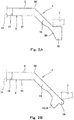
Figs. 2A and 2B are diagrams for explaining the spinning forming method. -
Fig. 3 is a schematic configuration diagram of a spinning forming device configured to execute the spinning forming method. -
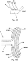
Fig. 4A is a cross-sectional view of a heater, andFig. 4B is a plan view of the heater. -
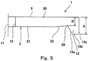
Fig. 5 is a cross-sectional view of the plate of a modified example. -
Fig. 6A shows a temperature distribution in the plate ofFig. 5 when ironing shifts to bending.Fig. 6B shows a temperature distribution in the plate ofFig. 1 when ironing shifts to bending. -
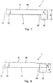
Fig. 7 is a cross-sectional view of the plate of another modified example. -
Fig. 8 is a cross-sectional view of the plate of yet another modified example. - A spinning forming method according to one embodiment of the present invention is a method for manufacturing a hollow structure including an inward swelling portion 15 at a large-diameter end portion of a
tapered portion 14 as shown inFig. 2B . A cross-sectional shape of thetapered portion 14 may be a linear shape or a curved shape. In the spinning forming method of the present embodiment, first, aplate 1 shown inFig. 1 is prepared. - The
plate 1 includes aback surface 2 and afront surface 3. Theback surface 2 becomes an inner surface of the hollow structure shown inFig. 2B , and thefront surface 3 becomes an outer surface of the hollow structure. Theplate 1 is symmetrical around acentral axis 11 and has a circular contour in a plan view. A circular throughhole 12 is provided at a center of theplate 1. The throughhole 12 is utilized for positioning with respect to a below-describedreceiving jig 52. However, theplate 1 does not necessarily have to be provided with the throughhole 12. A material of theplate 1 is not especially limited but is, for example, titanium alloy. - A ring-shaped
projection 13 is formed at theback surface 2 of theplate 1 along an outer peripheral edge of theplate 1. In the present embodiment, theprojection 13 is formed so as to constitute a part of an outer peripheral surface of theplate 1. However, theprojection 13 may be formed so as to be separated inward from the outer peripheral surface of theplate 1. Further, theprojection 13 does not necessarily have to be continuous in a circumferential direction and may be constituted by a plurality of circular-arc pieces separated from one another in the circumferential direction. - It is desirable that the
front surface 3 of theplate 1 be flat at least from a formingstart point 30 to a position above theprojection 13. The formingstart point 30 is a position on thefront surface 3 of theplate 1 against which position a below-describedprocessing tool 7 is first pressed. To be specific, a predetermined range from the formingstart point 30 to an outer side of the formingstart point 30 becomes the tapered portion 14 (seeFig. 2A ). - In the present embodiment, the entire
front surface 3 is flat. However, thefront surface 3 may be concave or bulge at an inner side of the formingstart point 30. Or, when theprojection 13 is formed so as to be separated inward from the outer peripheral surface of theplate 1, thefront surface 3 may be concave or bulge at a position between theprojection 13 and the outer peripheral surface of theplate 1. - More specifically, the
back surface 2 includes areference surface 21, an outward-facinginclined surface 22, anannular surface 23, and an inward-facinginclined surface 24 which are located at the inner side of theprojection 13. Thesesurfaces 21 to 24 are lined up in this order from a center side to the outer side. - The
reference surface 21 and theannular surface 23 are parallel to thefront surface 3. Theannular surface 23 is located closer to thefront surface 3 than thereference surface 21. To be specific, a thickness C between theannular surface 23 and thefront surface 3 is a minimum thickness of theplate 1. The minimum thickness of theplate 1 is, for example, 10 mm or more. - The outward-facing
inclined surface 22 exists between the formingstart point 30 of thefront surface 3 and theprojection 13. In the present embodiment, an outer peripheral edge of thereference surface 21 is located at a radially outer side of a position right under the formingstart point 30 of thefront surface 3. However, the outer peripheral edge of thereference surface 21 may be located right under the formingstart point 30 of thefront surface 3 or may be located at a radially inner side of the position right under the formingstart point 30. - The outward-facing
inclined surface 22 is inclined from the outer peripheral edge of thereference surface 21 so as to approach thefront surface 3 toward the radially outer side. To be specific, a portion between the outward-facinginclined surface 22 and thefront surface 3 is a thinning portion that decreases in thickness toward the radially outer side. An inclination angle of the outward-facinginclined surface 22 with respect to thefront surface 3 is relatively small (for example, 30° or less). Theannular surface 23 connects an outer peripheral edge of the outward-facinginclined surface 22 and an inner peripheral edge of the inward-facinginclined surface 24. However, theannular surface 23 may be omitted, and the outer peripheral edge of the outward-facinginclined surface 22 may be directly connected to the inner peripheral edge of the inward-facinginclined surface 24. - The inward-facing
inclined surface 24 existing between the outward-facinginclined surface 22 and theprojection 13 is inclined from an outer peripheral edge of theannular surface 23 so as to be away from thefront surface 3 toward the radially outer side. An inclination angle of the inward-facinginclined surface 24 with respect to thefront surface 3 is relatively small (for example, 30° or less). - In the present embodiment, a cross-sectional shape of the
projection 13 is a substantially trapezoidal shape that is pointed downward. To be specific, theprojection 13 includes: atip end surface 13b parallel to thefront surface 3 of theplate 1; a tubular outerperipheral surface 13c located on the outer peripheral edge of theplate 1; and an innerperipheral surface 13a inclined so as to approach the outerperipheral surface 13c toward thetip end surface 13b. Each of the innerperipheral surface 13a and thetip end surface 13b is also a part of theback surface 2 of theplate 1. The outerperipheral surface 13c may be inclined so as to approach the innerperipheral surface 13a toward thetip end surface 13b. In this case, the outerperipheral surface 13c is also a part of theback surface 2 of theplate 1. An inclination angle of the innerperipheral surface 13a with respect to thefront surface 3 is, for example, 60° to 65°. - The
plate 1 is configured such that a ratio R (R = B/A) of B to A is 0.7 or less, where A denotes a thickness at a tip end of theprojection 13, and B denotes a thickness at areference position 20 that is a position where an inclination of a portion of theback surface 2 which portion extends toward the tip end of theprojection 13 is 45° or more. In the present embodiment, thereference position 20 is an intersection point of the inward-facinginclined surface 24 and the innerperipheral surface 13a of theprojection 13. - In the spinning forming method of the present embodiment, after the
plate 1 is prepared, ironing and bending are performed while rotating theplate 1 by using aspinning forming device 4 shown inFig. 3 . For simplifying the drawings,Fig. 3 shows a simplified shape of theplate 1. - Specifically, the
spinning forming device 4 includes: a rotatingshaft 51 configured to rotate theplate 1; the receivingjig 52 interposed between therotating shaft 51 and theplate 1; and a fixingjig 61. The receivingjig 52 is attached to therotating shaft 51 and supports a center portion of theplate 1, and the fixingjig 61 sandwiches theplate 1 together with the receivingjig 52. Thespinning forming device 4 further includes: theprocessing tool 7 configured to be pressed against the front surface of theplate 1; and aheater 8 configured to locally heat a portion of theplate 1 against which portion theprocessing tool 7 is pressed. - In the present embodiment, the
heater 8 locally heats a part (the portion against which theprocessing tool 7 is pressed) of theplate 1 by induction heating. However, theheater 8 may locally heat a part of theplate 1 by laser. Or, theheater 8 configured to locally heat a part of theplate 1 may be a gas burner or the like. Further, in the present embodiment, theheater 8 is arranged so as to face thefront surface 3 of theplate 1. To be specific, theheater 8 heats the portion of theplate 1 against which portion theprocessing tool 7 is pressed, from thefront surface 3 side of theplate 1. The heating by theheater 8 is performed simultaneously with the pressing by theprocessing tool 7. It should be noted that the heating by theheater 8 may be performed continuously or intermittently while theprocessing tool 7 is pressed against theplate 1. - In the present embodiment, an axial direction of the
rotating shaft 51 is a vertical direction. However, the axial direction of therotating shaft 51 may be a horizontal direction or an oblique direction. A lower portion of therotating shaft 51 is supported by abase 41, and therotating shaft 51 is rotated by a motor, not shown. An upper surface of therotating shaft 51 is flat, and the receivingjig 52 is fixed to the upper surface. - The fixing
jig 61 is attached to a pressurizingrod 62. The pressurizingrod 62 is rotatably supported by a supportingportion 63. The supportingportion 63 is driven by a drivingportion 64 in an upward/downward direction. The drivingportion 64 is attached to aframe 42 arranged above the rotatingshaft 51. It should be noted that the fixingjig 61 may be omitted, and theplate 1 may be directly fixed to the receivingjig 52 by, for example, bolts. - The
processing tool 7 is moved outward in the radial direction while being pressed against thefront surface 3 of theplate 1 that is rotating. In the present embodiment, used as theprocessing tool 7 is a roller that follows the rotation of theplate 1 to rotate and has a trapezoidal cross section. However, the roller used as theprocessing tool 7 may have a rhombic cross section or a long round cross section. Theprocessing tool 7 may be, for example, a spatula. - More specifically, the
processing tool 7 is moved in the radial direction of therotating shaft 51 by a first radialdirection movement mechanism 44 and also moved in the axial direction of therotating shaft 51 by a first axialdirection movement mechanism 43 through the first radialdirection movement mechanism 44. The first axialdirection movement mechanism 43 extends so as to couple the base 41 and theframe 42. - During the forming, the
heater 8 is arranged on substantially the same circumference as theprocessing tool 7 and is moved in synchronization with theprocessing tool 7. More specifically, theheater 8 is moved in the radial direction of therotating shaft 51 by a second radialdirection movement mechanism 46 and also moved in the axial direction of therotating shaft 51 by a second axialdirection movement mechanism 45 through the second radialdirection movement mechanism 46. The second axialdirection movement mechanism 45 extends so as to couple the base 41 and theframe 42. - A relative positional relation between the
heater 8 and theprocessing tool 7 in the circumferential direction of therotating shaft 51 is not especially limited. For example, theheater 8 may be arranged at a position right opposite to theprocessing tool 7 across the rotatingshaft 51 or may be arranged at a position displaced from the position right opposite to theprocessing tool 7 across the rotating shaft 51 (for example, a position away from theprocessing tool 7 by 90° in the circumferential direction of the rotating shaft 51). - As shown in
Figs. 4A and 4B , theheater 8 includes anelectric conducting pipe 81 and acore 85. Theelectric conducting pipe 81 includes acoil portion 82, and thecore 85 collects magnetic flux generated around thecoil portion 82. Thecoil portion 82 has a doubled circular-arc shape extending in a rotational direction of theplate 1 and facing theplate 1. An opening angle (angle between both end portions) of thecoil portion 82 is, for example, 60° to 120°. Thecore 85 is constituted by one innerperipheral piece 86 and two outerperipheral pieces 87. The innerperipheral piece 86 covers an inner circular-arc portion 83 of thecoil portion 82 from an opposite side of theplate 1, and the outerperipheral pieces 87 cover respective outer circular-arc portions 84 of thecoil portion 82 from the opposite side of theplate 1. - A cooling liquid flows in the
electric conducting pipe 81. Further, an alternating voltage is applied to theelectric conducting pipe 81. A frequency of the alternating voltage is not especially limited but is desirably a high frequency of 5 k to 400 kHz. To be specific, the induction heating performed by theheater 8 is desirably high frequency induction heating. - Next, operations of the
spinning forming device 4 will be explained. - First, the
plate 1 is rotated by the rotatingshaft 51 with theplate 1 sandwiched between the receivingjig 52 and the fixingjig 61. Next, theprocessing tool 7 and theheater 8 are moved to respective positions close to the formingstart point 30 of thefront surface 3 of theplate 1, and theheater 8 locally heats the formingstart point 30 of theplate 1. Next, after theprocessing tool 7 is pressed against the formingstart point 30, theprocessing tool 7 and theheater 8 are moved obliquely downward and outward in the radial direction in synchronization with each other. To be specific, while pressing theprocessing tool 7 against thefront surface 3 of theplate 1 that is rotating, theprocessing tool 7 is moved outward in the radial direction from the inner side of theprojection 13 to a position above theprojection 13, and a portion of theplate 1 against which portion theprocessing tool 7 is pressed is locally heated. - Each of a movement speed VI of the
processing tool 7 in the axial direction of therotating shaft 51 and a movement speed V2 of theprocessing tool 7 in the radial direction of therotating shaft 51 may be constant at all times during the forming. Or, one or both of the movement speeds V1 and V2 may change during the forming. - According to the above operations of the
spinning forming device 4, the ironing is performed at the inner side of theprojection 13 by the pressing of theprocessing tool 7. With this, as shown inFig. 2A , a predetermined range (from the formingstart point 30 to the projection 13) at the inner side of theprojection 13 of theplate 1 becomes the taperedportion 14. - If the thickness B at the reference position that is a base point of the inner
peripheral surface 13a of the ring-shapedprojection 13 is not so different from the thickness A at the tip end of the projection A, and the ratio R (= B/A) is higher than 0.7 (in other words, the height of theprojection 13 is small), the ironing is performed even in a range where theprojection 13 exists. To be specific, theprojection 13 just deforms in the axial direction of therotating shaft 51 by the pressing of theprocessing tool 7. - On the other hand, according to the present embodiment, the thickness B at the
reference position 20 is adequately smaller than the thickness A at the tip end of theprojection 13. In addition, the portion of theplate 1 against which portion theprocessing tool 7 is pressed is locally heated. Therefore, when theprocessing tool 7 passes through a position above thereference position 20, as shown inFig. 2B , the bending is performed at a fulcrum that is a portion located at the inner side of and adjacent to thereference position 20 and softened by local heating, and theprojection 13 tilts toward the radially inner side. With this, the inward swelling portion 15 is formed at the large-diameter end portion of the taperedportion 14. It should be noted that since the volume of theprojection 13 decreases by the tilting of theprojection 13 toward the radially inner side, aburr 16 is formed at the outer side of theprocessing tool 7 by the remaining volume. - To be specific, according to the spinning forming method of the present embodiment, the ironing and the bending can be sequentially performed only by continuously moving the
processing tool 7 outward in the radial direction. Therefore, the hollow structure including the inward swelling portion 15 at the large-diameter end portion of the taperedportion 14 can be easily manufactured. - Further, in the present embodiment, since the portion of the
plate 1 against which portion theprocessing tool 7 is pressed is heated from thefront surface 3 of theplate 1, the rigidity of the tip end of theprojection 13 is maintained. Therefore, the bending at the fulcrum that is the portion located at the inner side of and adjacent to thereference position 20 can be more satisfactorily performed than a case where the portion of theplate 1 against which portion theprocessing tool 7 is pressed is heated from theback surface 2 side of theplate 1. - It is desirable that the ratio R of the thickness B at the
reference position 20 to the thickness A at the tip end of theprojection 13 of theplate 1 be 0.2 or more. If the ratio R is too low, theplate 1 may break during the bending depending on the material of theplate 1. The reason why such break occurs is because if the thickness B at thereference position 20 is too small, theplate 1 cannot endure a load of tensile stress generated by the ironing. In contrast, when the ratio R is 0.2 or more, the possibility of such break can be reduced. The ratio R is more desirably 0.3 or more and further desirably 0.4 or more. - The present invention is not limited to the above embodiment, and various modifications may be made within the scope of the present invention.
- For example, in the above embodiment, the
back surface 2 of theplate 1 is constituted by a plurality of flat surfaces each having a linear cross section. However, theback surface 2 of theplate 1 may be constituted by one continuous curved surface. - The
back surface 2 of theplate 1 does not necessarily have to include the inward-facinginclined surface 24 at the inner side of theprojection 13. For example, as shown inFig. 5 , thereference position 20 that is a position where the inclination of the portion of theback surface 2 which portion extends toward the tip end of theprojection 13 is 45° or more may be an intersection point of the outward-facinginclined surface 22 and the innerperipheral surface 13a of theprojection 13. - It should be noted that when the inward-facing
inclined surface 24 exists between the outward-facinginclined surface 22 and theprojection 13 as in the above embodiment, a concave portion is formed at theback surface 2 of theplate 1 so as to be located at the inner side of thereference position 20. As a result, especially in a case where theplate 1 is heated from thefront surface 3 side, when the ironing shifts to the bending, the heat can reach a portion close to theback surface 2 in a normal direction of the taperedportion 14. With this, the portion located at the inner side of and adjacent to thereference position 20 is kept at a high temperature, and the bending at this portion as the fulcrum can be further satisfactorily performed. -
Fig. 6A shows a temperature distribution in theplate 1 ofFig. 5 when the ironing shifts to the bending.Fig. 6B shows a temperature distribution in theplate 1 ofFig. 1 when the ironing shifts to the bending. The above effects can be confirmed fromFigs. 6A and 6B . - The
back surface 2 of theplate 1 does not necessarily have to include the outward-facinginclined surface 22 at the inner side of theprojection 13. For example, as shown inFig. 7 , theback surface 2 of theplate 1 may be flat except for theprojection 13. However, as shown inFigs. 1 and5 , when theback surface 2 of theplate 1 includes the outward-facinginclined surface 22 at the inner side of theprojection 13, in other words, when theplate 1 includes the thinning portion that exists at the inner side of theprojection 13 and decreases in thickness toward the radially outer side, the thickness of theplate 1 decreases as the ironing proceeds, and therefore, a load acting on theprocessing tool 7 during the ironing can be gradually reduced. It should be noted that, for example, as shown inFig. 8 , the thinning portion existing at the inner side of theprojection 13 may be a portion between theflat back surface 2 and an outward-facing inclined surface formed at thefront surface 3. As shown inFig. 8 , when thefront surface 3 of theplate 1 is inclined above theprojection 13, the thickness A at the tip end of theprojection 13 denotes a maximum distance between the tip end of theprojection 13 and thefront surface 3. - The cross-sectional shape of the
projection 13 does not necessarily have to be a trapezoidal shape. For example, as shown inFig. 7 , the cross-sectional shape of theprojection 13 may be a rectangular shape. Or, the cross-sectional shape of theprojection 13 may be a triangular shape, a mountain shape (such as a sine curve), or the like. - The minimum thickness of the
plate 1 may be less than 10 mm. -
- 1
- plate
- 13
- projection
- 2
- back surface
- 20
- reference position
- 22
- outward-facing inclined surface
- 24
- inward-facing inclined surface
- 3
- front surface
- 30
- forming start point
- 7
- processing tool
Claims (8)
- A spinning forming method comprising:preparing a plate including a back surface at which a ring-shaped projection is formed along an outer peripheral edge of the plate, a ratio of a thickness at a reference position of the plate to a thickness at a tip end of the projection being 0.7 or less, the reference position being a position where an inclination of a portion of the back surface which portion extends toward the tip end of the projection is 45° or more;rotating the plate;moving a processing tool outward in a radial direction from an inner side of the projection to a position above the projection while pressing the processing tool against a front surface of the plate that is rotating; andlocally heating a portion of the plate against which portion the processing tool is pressed.
- The spinning forming method according to claim 1, wherein the portion of the plate against which portion the processing tool is pressed is heated from the front surface side of the plate.
- The spinning forming method according to claim 1 or 2, wherein the plate includes a thinning portion at the inner side of the projection, the thinning portion decreasing in thickness toward a radially outer side.
- The spinning forming method according to claim 3, wherein:the front surface of the plate is flat at least from a forming start point to the position above the projection; andthe back surface of the plate includes an outward-facing inclined surface between the forming start point and the projection, the outward-facing inclined surface being inclined so as to approach the front surface toward the radially outer side.
- The spinning forming method according to claim 4, wherein the back surface of the plate includes an inward-facing inclined surface between the outward-facing inclined surface and the projection, the inward-facing inclined surface being inclined so as to be away from the front surface toward the radially outer side.
- The spinning forming method according to any one of claims 1 to 5, wherein the ratio of the thickness at the reference position to the thickness at the tip end of the projection is 0.2 or more.
- The spinning forming method according to any one of claims 1 to 6, wherein the plate is made of titanium alloy.
- The spinning forming method according to any one of claims 1 to 7, wherein a minimum thickness of the plate is 10 mm or more.
Applications Claiming Priority (2)
| Application Number | Priority Date | Filing Date | Title |
|---|---|---|---|
| JP2016138212A JP6705711B2 (en) | 2016-07-13 | 2016-07-13 | Spinning molding method |
| PCT/JP2017/025261 WO2018012494A1 (en) | 2016-07-13 | 2017-07-11 | Spin-molding method |
Publications (3)
| Publication Number | Publication Date |
|---|---|
| EP3485993A1 true EP3485993A1 (en) | 2019-05-22 |
| EP3485993A4 EP3485993A4 (en) | 2020-03-18 |
| EP3485993B1 EP3485993B1 (en) | 2026-04-29 |
Family
ID=60952084
Family Applications (1)
| Application Number | Title | Priority Date | Filing Date |
|---|---|---|---|
| EP17827621.8A Active EP3485993B1 (en) | 2016-07-13 | 2017-07-11 | Spinning forming method |
Country Status (5)
| Country | Link |
|---|---|
| US (1) | US11117177B2 (en) |
| EP (1) | EP3485993B1 (en) |
| JP (1) | JP6705711B2 (en) |
| CN (1) | CN109414744B (en) |
| WO (1) | WO2018012494A1 (en) |
Families Citing this family (4)
| Publication number | Priority date | Publication date | Assignee | Title |
|---|---|---|---|---|
| CN109622714A (en) * | 2019-01-23 | 2019-04-16 | 西安深瞳智控技术有限公司 | A kind of the head-shield rotary pressing moulding device and its manufacturing process of target seeker |
| CN112404227B (en) * | 2020-11-26 | 2023-10-27 | 首都航天机械有限公司 | Spinning forming method for seal head with fork-shaped ring structure |
| DE102020133114A1 (en) * | 2020-12-11 | 2022-06-15 | Vibracoustic Se | Rotatable component, tool and method for producing a rotatable component |
| CN116274371B (en) * | 2023-03-31 | 2026-05-01 | 西安博赛旋压科技有限公司 | Six-wheel powerful offset spinning forming method for large-diameter pure titanium cylindrical part |
Family Cites Families (9)
| Publication number | Priority date | Publication date | Assignee | Title |
|---|---|---|---|---|
| US1795379A (en) * | 1926-07-05 | 1931-03-10 | Schmidt Carl | Method of making flanged cup-shaped metal parts |
| DE2148519A1 (en) * | 1971-09-29 | 1973-04-05 | Ottensener Eisenwerk Gmbh | METHOD AND DEVICE FOR HEATING AND BOARDING RUBBES |
| JPS542262A (en) * | 1977-06-08 | 1979-01-09 | Mitsubishi Heavy Ind Ltd | Method and apparatus for roll forming |
| JPS57165129A (en) * | 1981-03-31 | 1982-10-12 | Matsushita Electric Works Ltd | Roll for spinning |
| US6158261A (en) * | 1997-07-14 | 2000-12-12 | General Electric Company | Mill for producing axially symmetric parts |
| US6006569A (en) * | 1998-04-27 | 1999-12-28 | Shrayer; Emmanuil | Method for manufacturing a dome from an undersized blank |
| JP6445776B2 (en) | 2014-04-11 | 2018-12-26 | 川崎重工業株式会社 | Spinning molding method |
| JP6445779B2 (en) | 2014-04-21 | 2018-12-26 | 川崎重工業株式会社 | Preliminary body and method for manufacturing axisymmetric parts |
| JP2015208766A (en) * | 2014-04-28 | 2015-11-24 | 川崎重工業株式会社 | Spinning molding device |
-
2016
- 2016-07-13 JP JP2016138212A patent/JP6705711B2/en active Active
-
2017
- 2017-07-11 CN CN201780043372.4A patent/CN109414744B/en not_active Expired - Fee Related
- 2017-07-11 EP EP17827621.8A patent/EP3485993B1/en active Active
- 2017-07-11 WO PCT/JP2017/025261 patent/WO2018012494A1/en not_active Ceased
- 2017-07-11 US US16/317,944 patent/US11117177B2/en active Active
Also Published As
| Publication number | Publication date |
|---|---|
| JP6705711B2 (en) | 2020-06-03 |
| US11117177B2 (en) | 2021-09-14 |
| US20200298299A1 (en) | 2020-09-24 |
| EP3485993B1 (en) | 2026-04-29 |
| WO2018012494A1 (en) | 2018-01-18 |
| EP3485993A4 (en) | 2020-03-18 |
| CN109414744B (en) | 2020-12-22 |
| JP2018008289A (en) | 2018-01-18 |
| CN109414744A (en) | 2019-03-01 |
Similar Documents
| Publication | Publication Date | Title |
|---|---|---|
| EP3485993B1 (en) | Spinning forming method | |
| EP3006135B1 (en) | Spinning thickening forming method and spinning thickening forming apparatus | |
| EP2883629B1 (en) | Spinning molding device and molding method | |
| US9931682B2 (en) | Spinning forming device and spinning forming method | |
| EP3165299A1 (en) | Spin forming device | |
| US10882094B2 (en) | Spinning forming method | |
| EP3135397B1 (en) | Method of manufacturing preliminary formed body and axisymmetrical component | |
| US20170304885A1 (en) | Spinning forming method | |
| EP3095535B1 (en) | Spinning forming device | |
| CN104582869B (en) | Spinning forming method and spinning forming device |
Legal Events
| Date | Code | Title | Description |
|---|---|---|---|
| STAA | Information on the status of an ep patent application or granted ep patent |
Free format text: STATUS: THE INTERNATIONAL PUBLICATION HAS BEEN MADE |
|
| PUAI | Public reference made under article 153(3) epc to a published international application that has entered the european phase |
Free format text: ORIGINAL CODE: 0009012 |
|
| STAA | Information on the status of an ep patent application or granted ep patent |
Free format text: STATUS: REQUEST FOR EXAMINATION WAS MADE |
|
| 17P | Request for examination filed |
Effective date: 20190123 |
|
| AK | Designated contracting states |
Kind code of ref document: A1 Designated state(s): AL AT BE BG CH CY CZ DE DK EE ES FI FR GB GR HR HU IE IS IT LI LT LU LV MC MK MT NL NO PL PT RO RS SE SI SK SM TR |
|
| AX | Request for extension of the european patent |
Extension state: BA ME |
|
| DAV | Request for validation of the european patent (deleted) | ||
| DAX | Request for extension of the european patent (deleted) | ||
| A4 | Supplementary search report drawn up and despatched |
Effective date: 20200218 |
|
| RIC1 | Information provided on ipc code assigned before grant |
Ipc: B21D 53/26 20060101ALI20200212BHEP Ipc: B21D 37/16 20060101ALI20200212BHEP Ipc: B21D 22/18 20060101ALI20200212BHEP Ipc: B21D 22/14 20060101AFI20200212BHEP Ipc: B21H 1/00 20060101ALI20200212BHEP |
|
| STAA | Information on the status of an ep patent application or granted ep patent |
Free format text: STATUS: EXAMINATION IS IN PROGRESS |
|
| 17Q | First examination report despatched |
Effective date: 20230523 |
|
| TPAC | Observations filed by third parties |
Free format text: ORIGINAL CODE: EPIDOSNTIPA |
|
| GRAP | Despatch of communication of intention to grant a patent |
Free format text: ORIGINAL CODE: EPIDOSNIGR1 |
|
| STAA | Information on the status of an ep patent application or granted ep patent |
Free format text: STATUS: GRANT OF PATENT IS INTENDED |
|
| INTG | Intention to grant announced |
Effective date: 20260114 |
|
| GRAS | Grant fee paid |
Free format text: ORIGINAL CODE: EPIDOSNIGR3 |
|
| GRAA | (expected) grant |
Free format text: ORIGINAL CODE: 0009210 |
|
| STAA | Information on the status of an ep patent application or granted ep patent |
Free format text: STATUS: THE PATENT HAS BEEN GRANTED |
|
| AK | Designated contracting states |
Kind code of ref document: B1 Designated state(s): AL AT BE BG CH CY CZ DE DK EE ES FI FR GB GR HR HU IE IS IT LI LT LU LV MC MK MT NL NO PL PT RO RS SE SI SK SM TR |
|
| REG | Reference to a national code |
Ref country code: CH Ref legal event code: F10 Free format text: ST27 STATUS EVENT CODE: U-0-0-F10-F00 (AS PROVIDED BY THE NATIONAL OFFICE) Effective date: 20260429 Ref country code: GB Ref legal event code: FG4D |
|
| REG | Reference to a national code |
Ref country code: DE Ref legal event code: R096 Ref document number: 602017095044 Country of ref document: DE |
|
| REG | Reference to a national code |
Ref country code: IE Ref legal event code: FG4D |