EP3485844A1 - Tooth-whitening device - Google Patents
Tooth-whitening device Download PDFInfo
- Publication number
- EP3485844A1 EP3485844A1 EP18205598.8A EP18205598A EP3485844A1 EP 3485844 A1 EP3485844 A1 EP 3485844A1 EP 18205598 A EP18205598 A EP 18205598A EP 3485844 A1 EP3485844 A1 EP 3485844A1
- Authority
- EP
- European Patent Office
- Prior art keywords
- tooth
- whitening
- gas
- discharger
- outlet
- Prior art date
- Legal status (The legal status is an assumption and is not a legal conclusion. Google has not performed a legal analysis and makes no representation as to the accuracy of the status listed.)
- Withdrawn
Links
- 239000012530 fluid Substances 0.000 claims abstract description 58
- 210000000214 mouth Anatomy 0.000 claims abstract description 35
- CURLTUGMZLYLDI-UHFFFAOYSA-N Carbon dioxide Chemical compound O=C=O CURLTUGMZLYLDI-UHFFFAOYSA-N 0.000 claims abstract description 34
- 229910002092 carbon dioxide Inorganic materials 0.000 claims abstract description 17
- 239000001569 carbon dioxide Substances 0.000 claims abstract description 17
- 239000000463 material Substances 0.000 claims description 27
- 229910052710 silicon Inorganic materials 0.000 claims description 4
- 239000010703 silicon Substances 0.000 claims description 4
- 239000007789 gas Substances 0.000 description 96
- 150000003254 radicals Chemical class 0.000 description 13
- 230000002378 acidificating effect Effects 0.000 description 10
- 230000002087 whitening effect Effects 0.000 description 10
- XLYOFNOQVPJJNP-UHFFFAOYSA-N water Substances O XLYOFNOQVPJJNP-UHFFFAOYSA-N 0.000 description 9
- 230000000694 effects Effects 0.000 description 8
- 239000004480 active ingredient Substances 0.000 description 5
- 230000002411 adverse Effects 0.000 description 3
- 238000000034 method Methods 0.000 description 3
- 239000000126 substance Substances 0.000 description 3
- XKRFYHLGVUSROY-UHFFFAOYSA-N Argon Chemical compound [Ar] XKRFYHLGVUSROY-UHFFFAOYSA-N 0.000 description 2
- BZHJMEDXRYGGRV-UHFFFAOYSA-N Vinyl chloride Chemical compound ClC=C BZHJMEDXRYGGRV-UHFFFAOYSA-N 0.000 description 2
- 239000003990 capacitor Substances 0.000 description 2
- 238000004040 coloring Methods 0.000 description 2
- 230000005494 condensation Effects 0.000 description 2
- 238000009833 condensation Methods 0.000 description 2
- 238000010586 diagram Methods 0.000 description 2
- 210000000056 organ Anatomy 0.000 description 2
- 239000011347 resin Substances 0.000 description 2
- 229920005989 resin Polymers 0.000 description 2
- IJGRMHOSHXDMSA-UHFFFAOYSA-N Atomic nitrogen Chemical compound N#N IJGRMHOSHXDMSA-UHFFFAOYSA-N 0.000 description 1
- MYMOFIZGZYHOMD-UHFFFAOYSA-N Dioxygen Chemical compound O=O MYMOFIZGZYHOMD-UHFFFAOYSA-N 0.000 description 1
- 239000004677 Nylon Substances 0.000 description 1
- 239000004743 Polypropylene Substances 0.000 description 1
- XAGFODPZIPBFFR-UHFFFAOYSA-N aluminium Chemical compound [Al] XAGFODPZIPBFFR-UHFFFAOYSA-N 0.000 description 1
- 229910052782 aluminium Inorganic materials 0.000 description 1
- 229910052786 argon Inorganic materials 0.000 description 1
- 238000001816 cooling Methods 0.000 description 1
- 230000007423 decrease Effects 0.000 description 1
- 230000003247 decreasing effect Effects 0.000 description 1
- 229910001873 dinitrogen Inorganic materials 0.000 description 1
- 229910001882 dioxygen Inorganic materials 0.000 description 1
- 230000005669 field effect Effects 0.000 description 1
- 238000009434 installation Methods 0.000 description 1
- 229920001778 nylon Polymers 0.000 description 1
- -1 polypropylene Polymers 0.000 description 1
- 229920001155 polypropylene Polymers 0.000 description 1
- 230000035484 reaction time Effects 0.000 description 1
- 239000004065 semiconductor Substances 0.000 description 1
- 238000001179 sorption measurement Methods 0.000 description 1
Images

Classifications
-
- A—HUMAN NECESSITIES
- A61—MEDICAL OR VETERINARY SCIENCE; HYGIENE
- A61C—DENTISTRY; APPARATUS OR METHODS FOR ORAL OR DENTAL HYGIENE
- A61C19/00—Dental auxiliary appliances
- A61C19/06—Implements for therapeutic treatment
- A61C19/063—Medicament applicators for teeth or gums, e.g. treatment with fluorides
- A61C19/066—Bleaching devices; Whitening agent applicators for teeth, e.g. trays or strips
-
- A—HUMAN NECESSITIES
- A61—MEDICAL OR VETERINARY SCIENCE; HYGIENE
- A61C—DENTISTRY; APPARATUS OR METHODS FOR ORAL OR DENTAL HYGIENE
- A61C17/00—Devices for cleaning, polishing, rinsing or drying teeth, teeth cavities or prostheses; Saliva removers; Dental appliances for receiving spittle
-
- A—HUMAN NECESSITIES
- A61—MEDICAL OR VETERINARY SCIENCE; HYGIENE
- A61C—DENTISTRY; APPARATUS OR METHODS FOR ORAL OR DENTAL HYGIENE
- A61C17/00—Devices for cleaning, polishing, rinsing or drying teeth, teeth cavities or prostheses; Saliva removers; Dental appliances for receiving spittle
- A61C17/02—Rinsing or air-blowing devices, e.g. using fluid jets or comprising liquid medication
- A61C17/0211—Rinsing or air-blowing devices, e.g. using fluid jets or comprising liquid medication specially adapted for rinsing the teeth of at least one jaw simultaneously
Definitions
- the present disclosure relates to a tooth-whitening device that supplies a tooth-whitening fluid to teeth.
- a known tooth-whitening device supplies a tooth-whitening fluid to teeth, using a mouthpiece.
- a tooth-whitening device disclosed in Japanese Patent Unexamined Publication No. 2015-229084 generates a tooth-whitening fluid by electric discharge, and supplies air containing the tooth-whitening fluid from a mouthpiece into an oral cavity.
- a conventional tooth-whitening device also generates an acidic component in line with electric discharge.
- acidity in the oral cavity becomes too high, due to various conditions, teeth may be adversely affected. Accordingly, generation of the acidic component in the oral cavity is preferably prevented as much as possible.
- a tooth-whitening device of the present disclosure includes a discharger that applies electric discharge to carbon dioxide gas to generate a tooth-whitening fluid.
- the tooth-whitening device of the present disclosure can successfully whiten teeth.
- a tooth-whitening device in a first exemplary embodiment of the present disclosure includes a discharger that applies electric discharge to carbon dioxide gas, so as to generate a tooth-whitening fluid.
- a discharger that applies electric discharge to carbon dioxide gas, so as to generate a tooth-whitening fluid.
- a tooth-whitening device in a second exemplary embodiment of the present disclosure further includes a feeder that supplies carbon dioxide gas to the discharger, in addition to the first exemplary embodiment.
- the discharger stably generates the tooth-whitening fluid.
- a tooth-whitening device in a third exemplary embodiment of the present disclosure includes a gas cylinder for storing carbon dioxide gas in the feeder, and the gas cylinder is detachably attached to the feeder, in addition to the second exemplary embodiment.
- the gas cylinder is used as a supply source of carbon dioxide gas, and thus a structure of the feeder can be simplified.
- a tooth-whitening device in a fourth exemplary embodiment of the present disclosure further includes a humidifier for generating humidified gas, in addition to the first exemplary embodiment.
- humidified gas can be supplied into the oral cavity together with the tooth-whitening fluid, and thus the tooth-whitening fluid can act on moistened teeth.
- a tooth-whitening device in a fifth exemplary embodiment of the present disclosure further includes an outlet provided with a supply port through which the tooth-whitening fluid is supplied into the oral cavity, and a hollow part for guiding to the outlet a gas containing tooth-whitening fluid generated by the discharger, in addition to the first exemplary embodiment.
- the tooth-whitening fluid generated by the discharger is supplied into the oral cavity through the hollow part and the outlet. Since the discharger is not included in the outlet, the outlet is light in weight. This improves usability.
- the hollow part includes an inner periphery that forms a gas flow path, in addition to the fifth exemplary embodiment.
- a material configuring the inner periphery includes a material that is positively-charged more easily than silicon.
- the tooth-whitening fluid contains an active ingredient having tooth-whitening effect.
- the active ingredient is, for example, OH radicals.
- a positively-charged substance adsorbs less OH radicals.
- the outlet includes an exhaust port through which a gas inside the oral cavity is released outside, in addition to the fifth exemplary embodiment.
- a structure of the device can be simplified, compared to a structure of releasing the gas inside the oral cavity to a main body of the tooth-whitening device.
- a flow rate of the tooth-whitening fluid supplied from the discharger is less than 1l/min.
- a flow velocity of the tooth-whitening fluid in the oral cavity is slow, and thus a long reaction time can be secured between a component sticking to teeth and the tooth-whitening fluid. A tooth-whitening effect can thus be enhanced.
- Fig. 1 is an example of tooth-whitening device 10 that supplies to teeth the tooth-whitening fluid for whitening teeth.
- the tooth-whitening fluid contains an active ingredient having a tooth-whitening effect.
- the tooth-whitening fluid is, for example, a gas containing charged particulate water.
- the charged particulate water contains radical species, which is the active ingredient.
- An example of the radical species is OH radicals.
- the charged particulate water containing radicals is, for example, nano-meter size fine droplets. Dew condensation of the charged particulate water containing radicals is generated by cooling an discharge electrode, for example, in discharger 22, which is described later, and then high voltage may be applied to the discharge electrode retaining dew condensation water.
- main body 20 As shown in Fig. 1 , major components configuring tooth-whitening device 10 are main body 20, hollow part 30, and outlet 40.
- Main body 20 is, for example, a box-shaped unit designed to be stably placed on various installation surfaces, including a rack, furniture, table, and floor.
- the shape and size of main body 20 can be selected arbitrarily.
- the shape and size of main body 20 are determined such that the user can carry main body 20 with a single hand.
- Main body 20 includes housing 21, discharger 22, humidifier 23, and operation part 24.
- Housing 21 is a resin box that is configured to house various components in its inner space.
- Discharger 22 is provided inside housing 21.
- Discharger 22 generates the tooth-whitening fluid by electric discharge.
- Humidifier 23 is provided inside housing 21. Humidifier 23 generates humid gas that is humidified gas. For example, humidifier 23 humidifies air.
- Operation part 24 is a user interface provided on housing 21, and includes a button and switch. The user can select various conditions for operating tooth-whitening device 10 by operating operation part 24.
- the user can determine whether or not to activate discharger 22 and whether or not to activate humidifier 23 by using this operation part 24.
- the user can also designate a flow rate of the gas containing the tooth-whitening fluid supplied from main body 20, and a flow rate of the gas containing humidified gas supplied from main body 20.
- Hollow part 30 connects main body 20 and outlet 40 such that hollow part 30 guides to outlet 40 the gas containing the tooth-whitening fluid generated by discharger 22.
- Hollow part 30 is, for example, a flexible hose.
- a method of attaching hollow part 30 to main body 20 and outlet 40 can be selected arbitrarily.
- Hollow part 30 may be detachably connected to main body 20 and outlet 40.
- hollow part 30 may be fixed onto main body 20 and outlet 40.
- a length of hollow part 30 can be selected arbitrarily.
- the length of hollow part 30 is selected from a range between 0.5 cm and 150 cm. In an example shown in Fig. 1 , the length of hollow part 30 is 30 cm.
- Gas flow path 31 is formed inside hollow part 30.
- Flow path 31 includes first flow path 31A and second flow path 31B.
- First flow path 31A guides to outlet 40 the gas containing the tooth-whitening fluid generated by discharger 22.
- Second flow path 31B guides to outlet 40 the gas containing humidified gas generated by humidifier 23.
- First flow path 31A and second flow path 31B are partitioned inside hollow part 30 so that the gas flowing in first flow path 31A and the gas flowing in second flow path 31B do not mix.
- a material for configuring hollow part 30 can be selected arbitrarily.
- at least a material configuring inner periphery 32 of hollow part 30 is a material that is positively charged more easily than silicon.
- a material that is positively charged more easily than silicon For example, polypropylene, nylon, vinyl chloride, and aluminum are used.
- a material configuring hollow part 30 is selected with reference to the triboelectric series.
- entire hollow part 30, including inner periphery 32 is configured with vinyl chloride from the viewpoint of its ease of charging and flexibility.
- a material easy to be positively-charged adsorbs less OH radicals. Accordingly, when the gas containing tooth-whitening fluid passes through first flow path 31A, OH radicals contained in the tooth-whitening fluid are hardly adsorbed to inner periphery 32 of hollow part 30.
- Outlet 40 is configured to supply the gas fed through hollow part 30 into an oral cavity.
- Outlet 40 preferably has a shape that can be held in the mouth or fitted around the mouth, so as to supply the gas into the oral cavity.
- outlet 40 is a mouthpiece.
- a material configuring outlet 40 can be selected arbitrarily.
- a resin material is used.
- a material configuring outlet 40 is preferably a material that is positively charged more easily than silicon.
- Outlet 40 is divided into curved part 41 and connector 42.
- Curved part 41 is a part that faces the front of teeth when outlet 40 is held in the mouth.
- Curved part 41 is curved along alignment of teeth.
- Curved part 41 has supply port 41A for supplying the gas into the oral cavity, and exhaust port 41B for releasing the gas in the oral cavity outside the oral cavity.
- Supply port 41A and exhaust port 41B are holes passing through curved part 41.
- the shape, size, and number of supply ports 41A and exhaust ports 41B can be selected arbitrarily.
- Supply port 41A and exhaust port 41B may be formed in any portion of curved part 41.
- one supply port 41A is formed at the center of curved part 41, and two exhaust ports 41B are formed each on both sides of supply port 41A.
- An opening area of exhaust port 41 is smaller than an opening area of supply port 41A.
- Connector 42 is connected to hollow part 30.
- Connector 42 guides the gas supplied from hollow part 30 to supply port 41A.
- Gas flow path 42A connected to supply port 41A are formed inside connector 42.
- First flow path 31A and second flow path 31B of hollow part 30 are connected to flow path 42A. The gas flowing in first flow path 31A is mixed with the gas flowing in second flow path 31B in flow path 42A.
- Fig. 2 is a block diagram of tooth-whitening device 10. As shown in Fig. 2 , main body 20 further includes feeder 25, multiple pipes 26, regulator 27, power unit 28, and controller 29. These components are disposed inside housing 21.
- Feeder 25 supplies to discharger 22 a material gas used for generating the tooth-whitening fluid.
- Feeder 25 includes gas cylinder 25A storing the material gas (e.g., carbon dioxide gas) and cylinder attachment part (not illustrated) configured to set detachable gas cylinder 25A.
- material gas e.g., carbon dioxide gas
- cylinder attachment part not illustrated
- a type of the material gas can be selected arbitrarily.
- a gas that generates less acidic component than air when used for generating tooth-whitening fluid by electric discharge is selected.
- Other than carbon dioxide gas, for example, oxygen gas, nitrogen gas, and argon gas are used.
- Multiple pipes 26 include first pipe 26A, second pipe 26B, and third pipe 26C.
- First pipe 26A is connected to a gas outlet of discharger 22.
- First flow path 31A of hollow part 30 is connected to a gas flow path inside first pipe 26A.
- Second pipe 26B is connected to a gas outlet of humidifier 23.
- Second flow path 31B of hollow part 30 is connected to a gas flow path inside second pipe 26B.
- Third pipe 26C is connected to a gas outlet of feeder 25 and a gas inlet of discharger 22.
- a space is formed for placing gas cylinder 25A in the cylinder attachment part of feeder 25. This space is covered with a cover (not illustrated) provided on housing 21. The cover is opened to attach gas cylinder 25A to the cylinder attachment part or remove gas cylinder 25A from the cylinder attachment part.
- Regulator 27 is provided on third pipe 26C. Regulator 27 is a solenoid valve for adjusting a flow rate of the material gas flowing in third pipe 26C.
- Power unit 28 includes a rectifying circuit and a capacitor.
- the rectifying circuit includes a diode bridge, and full-wave rectifies AC power supplied from commercial power supply 100.
- the capacitor removes noise in power rectified by the rectifying circuit.
- Power unit 28 supplies power to discharger 22, humidifier 23, regulator 27, and controller 29.
- Controller 29 is, for example, configured with CPU (Central Processing Unit) or MPU (Micro Processing Unit). Controller 29 controls discharger 22, humidifier 23, and regulator 27 in response to the operation input to operation part 24.
- CPU Central Processing Unit
- MPU Micro Processing Unit
- discharger 22 includes drive circuit 22A, resonance circuit 22B, laminated piezoelectric transformer 22C, and electrode 22D.
- Drive circuit 22A changes frequency of the power supplied from power unit 28. More specifically, drive circuit 22A includes a single-phase full-bridge inverter. This inverter has two arms connected in parallel. Each arm has two MOSFETs (metal-oxide-semiconductor field-effect transistors) connected in series.
- MOSFETs metal-oxide-semiconductor field-effect transistors
- Drive circuit 22A generates AC power with frequency higher than the frequency of AC power supplied from commercial power supply 100 by turning on and off these four MOSFETs.
- Laminated piezoelectric transformer 22C converts the voltage supplied from resonance circuit 22B to high voltage. More specifically, laminated piezoelectric transformer 22C includes the primary electrode electrically connected to resonance circuit 22B and a secondary electrode electrically connected to the electrode, and outputs transformed AC power to electrode 22D.
- Electrode 22D causes electric discharge by the power supplied from laminated piezoelectric transformer 22C to generate charged particulate water.
- Electric discharge caused by electrode 22D is, for example, corona discharge. Radical species in the charged particulate water generated by discharge contains OH radicals.
- outlet 40 is held in a mouth.
- Controller 29 controls discharger 22, humidifier 23, and regulator 27 in response to the operation input to operation part 24.
- tooth-whitening fluid When discharger 22 is activated, the tooth-whitening fluid is generated. A gas containing the tooth-whitening fluid passes through first flow path 31A of hollow part 30, flow path 42A of outlet 40, and supply port 41A, and flows into the oral cavity.
- Humidifier 23 is activated to generate humidified gas.
- the gas containing the humidified gas passes through second flow path 31B of hollow part 30, flow path 42A of outlet 40, and supply port 41A into the oral cavity.
- the tooth-whitening fluid is supplied to moistened teeth. Since moisture of the humidified gas attaches to oral organs, such as gum and tongue, these organs are unlikely dried during the use of tooth-whitening device 10.
- tooth-whitening device 10 An action of tooth-whitening device 10 is described.
- a tooth-whitening effect of the tooth-whitening fluid is enhanced when the tooth-whitening fluid is supplied to moistened teeth.
- a tooth surface When an acidic component attaches to a tooth for a long period, a tooth surface may be adversely affected.
- an effect of acidic component increases.
- tooth-whitening device 10 is configured to whiten a tooth efficiently while protecting the tooth. More specifically, tooth-whitening device 10 includes feeder 25 that supplies carbon dioxide gas to discharger 22, and discharger 22 that generates the tooth-whitening fluid by applying electric discharge to the carbon dioxide gas supplied from feeder 25.
- the gas after electric discharge does not substantially contain an acidic component. Accordingly, a gas containing the tooth-whitening fluid but not containing the acidic component is supplied from the outlet to the oral cavity. As a result, an adverse effect of the acidic component on the tooth surface can be suppressed.
- Tooth-whitening device 10 includes humidifier 23 for generating humidified gas.
- the humidified gas generated by humidifier 23 is supplied into the oral cavity, and its moisture attaches to tooth. Accordingly, the tooth-whitening fluid acts on moistened teeth. As a result, teeth are efficiently whitened.
- a test for confirming the whitening effect is conducted under the next test conditions.
- a specimen to be whitened by tooth-whitening device 10 is a porphyrin-dyed paper. This dyed paper is colored in brown.
- a material gas used for tooth-whitening device 10 is carbon dioxide gas. Multiple flow rates of the gas containing the tooth-whitening fluid supplied to the specimen from tooth-whitening device 10 are selected from a range between 0 L/minute and 5 L/minute.
- the flow rate is adjusted using a flow-meter with valve installed in the middle of third pipe 26C.
- the flow rate is adjusted by adjusting an opening degree of the valve with reference to indicated flow rate.
- the specimen is disposed at a certain distance from the tip of hollow part 30. This certain distance is selected with reference to a distance between supply port 41A and tooth when outlet 40 is held in the mouth. More specifically, the certain distance is 1 mm.
- Tooth-whitening device 10 continuously supplies the gas containing the tooth-whitening fluid to the specimen for a certain time.
- a certain time is selected. More specifically, the certain time is 30 minutes.
- a brightness difference is used as an index for evaluating the tooth-whitening effect.
- This brightness difference is a difference between a brightness of the specimen before the gas containing the tooth-whitening fluid is supplied and a brightness of the specimen after the gas containing the tooth-whitening fluid is supplied.
- the brightness difference is measured, using a color difference measuring instrument, based on the brightness of the specimen before the gas containing the tooth-whitening fluid is supplied and the brightness of the specimen after the gas containing the tooth-whitening fluid is supplied.
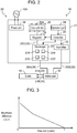
- Fig. 3 is an example of a test result.
- the X axis indicates the flow rate of the gas containing the tooth-whitening fluid supplied to the specimen.
- the Y axis indicates the brightness difference measured by the color difference measuring device. As shown in Fig. 3 , the brightness difference is almost 0, regardless of the flow rate of the gas containing the tooth-whitening fluid, when the flow rate of the gas containing the tooth-whitening fluid is 1 L/minute or above. In a range that the flow rate of the gas containing the tooth-whitening fluid is between greater than 0 L/minute and less than 1 L/minute, the brightness difference increases as the flow rate of the gas containing the tooth-whitening fluid decreases.
- the whitening effect differs by the flow rate due to the next reason.
- a flow velocity of the gas containing the tooth-whitening fluid becomes slower.
- the tooth-whitening fluid passes by after giving the whitening effect to the specimen. Accordingly, the whitening effect is enhanced.
- the flow rate is increased, the flow velocity of the gas containing the tooth-whitening fluid becomes faster.
- the tooth-whitening fluid passes by the specimen before it can give the whitening effect. Accordingly, the whitening effect is weakened.
- the above preferred embodiment describes an embodiment mode of the tooth-whitening device of the present disclosure, and is thus not considered to be restrictive.
- the tooth-whitening device of the present disclosure may include a modified example described below, in addition to the above preferred embodiment.
- feeder 25 of main body 20 can be changed arbitrarily.
- feeder 25 is provided on the outer face of housing 21.
- gas cylinder 25A attached to feeder 25 is also provided on the outer face of housing 21.
- Feeder 25 is, for example, a chamber configured to store material gas.
- the material gas is filled in feeder 25 in the next way.
- a separately prepared gas cylinder and feeder 25 are connected, such as by a hose.
- the material gas is supplied from the gas cylinder to feeder 25, and the chamber is filled with the material gas.
- connection between the gas cylinder and feeder 25 is released.
- Power unit 28 is configured to supply the power of a primary battery or a secondary battery to discharger 22, humidifier 23, regulator 27, and controller 29.
- a structure of hollow part 30 can be changed arbitrarily.
- a material configuring inner periphery 32 of hollow part 30 is, for example, different from a material configuring other portion of hollow part 30.
- the material configuring inner periphery 32 is preferably a material that is easy to be positively charged.
- Outlet 40 is, for example, a mask covering the mouth for supplying gas into the oral cavity.
- the mask preferably includes a portion covering the mouth and a portion held in the mouth.
- the portion held in the mouth has a supply port for supplying the gas into the oral cavity.
- Outlet 40 may also be a nozzle that can be held in the mouth.
- the present disclosure is applicable to home-use and business-use tooth-whitening devices.
Landscapes
- Health & Medical Sciences (AREA)
- Dentistry (AREA)
- Epidemiology (AREA)
- Life Sciences & Earth Sciences (AREA)
- Animal Behavior & Ethology (AREA)
- General Health & Medical Sciences (AREA)
- Public Health (AREA)
- Veterinary Medicine (AREA)
- Oral & Maxillofacial Surgery (AREA)
- Dental Tools And Instruments Or Auxiliary Dental Instruments (AREA)
Abstract
Tooth-whitening device (10) includes discharger (22) configured to generate a tooth-whitening fluid by applying electric discharge to carbon dioxide gas, feeder (25) configured to supply the carbon dioxide gas to the discharger, humidifier (23) configured to generate humidified gas, outlet (40) provided with a supply port through which the tooth-whitening fluid is supplied into an oral cavity, and hollow part (30) configured to guide to outlet (40) a gas containing the tooth-whitening fluid generated by discharger (22).
Description
- The present disclosure relates to a tooth-whitening device that supplies a tooth-whitening fluid to teeth.
- A known tooth-whitening device supplies a tooth-whitening fluid to teeth, using a mouthpiece. For example, a tooth-whitening device disclosed in Japanese Patent Unexamined Publication No.
2015-229084 - A conventional tooth-whitening device also generates an acidic component in line with electric discharge. In general, it is known that when acidity in the oral cavity becomes too high, due to various conditions, teeth may be adversely affected. Accordingly, generation of the acidic component in the oral cavity is preferably prevented as much as possible.
- A tooth-whitening device of the present disclosure includes a discharger that applies electric discharge to carbon dioxide gas to generate a tooth-whitening fluid.
- The tooth-whitening device of the present disclosure can successfully whiten teeth.
-
-
Fig. 1 is a perspective view of a tooth-whitening device in a preferred embodiment of the present disclosure. -
Fig. 2 is a block diagram of the tooth-whitening device in the preferred embodiment of the present disclosure. -
Fig. 3 is a graph showing an example of test results. - A tooth-whitening device in a first exemplary embodiment of the present disclosure includes a discharger that applies electric discharge to carbon dioxide gas, so as to generate a tooth-whitening fluid. When electric discharge is applied to carbon dioxide gas, less acidic component is formed. Accordingly, a condition that the acidic component attaches to teeth for a long time while using the tooth-whitening device hardly occurs in this exemplary embodiment.
- A tooth-whitening device in a second exemplary embodiment of the present disclosure further includes a feeder that supplies carbon dioxide gas to the discharger, in addition to the first exemplary embodiment. In this exemplary embodiment, the discharger stably generates the tooth-whitening fluid.
- A tooth-whitening device in a third exemplary embodiment of the present disclosure includes a gas cylinder for storing carbon dioxide gas in the feeder, and the gas cylinder is detachably attached to the feeder, in addition to the second exemplary embodiment. In this exemplary embodiment, the gas cylinder is used as a supply source of carbon dioxide gas, and thus a structure of the feeder can be simplified.
- A tooth-whitening device in a fourth exemplary embodiment of the present disclosure further includes a humidifier for generating humidified gas, in addition to the first exemplary embodiment. In this exemplary embodiment, humidified gas can be supplied into the oral cavity together with the tooth-whitening fluid, and thus the tooth-whitening fluid can act on moistened teeth.
- A tooth-whitening device in a fifth exemplary embodiment of the present disclosure further includes an outlet provided with a supply port through which the tooth-whitening fluid is supplied into the oral cavity, and a hollow part for guiding to the outlet a gas containing tooth-whitening fluid generated by the discharger, in addition to the first exemplary embodiment. In this exemplary embodiment, the tooth-whitening fluid generated by the discharger is supplied into the oral cavity through the hollow part and the outlet. Since the discharger is not included in the outlet, the outlet is light in weight. This improves usability.
- In a tooth-whitening device in a sixth exemplary embodiment of the present disclosure, the hollow part includes an inner periphery that forms a gas flow path, in addition to the fifth exemplary embodiment. A material configuring the inner periphery includes a material that is positively-charged more easily than silicon. The tooth-whitening fluid contains an active ingredient having tooth-whitening effect. The active ingredient is, for example, OH radicals. A positively-charged substance adsorbs less OH radicals. In this exemplary embodiment, when the hollow part as configured above can supply the tooth-whitening fluid containing a large amount of active ingredient into the oral cavity through the hollow part and the outlet.
- In a tooth-whitening device in a seventh exemplary embodiment of the present disclosure, the outlet includes an exhaust port through which a gas inside the oral cavity is released outside, in addition to the fifth exemplary embodiment. In this exemplary embodiment, a structure of the device can be simplified, compared to a structure of releasing the gas inside the oral cavity to a main body of the tooth-whitening device.
- In a tooth-whitening device in an eighth exemplary embodiment of the present disclosure, a flow rate of the tooth-whitening fluid supplied from the discharger is less than 1l/min. In this exemplary embodiment, a flow velocity of the tooth-whitening fluid in the oral cavity is slow, and thus a long reaction time can be secured between a component sticking to teeth and the tooth-whitening fluid. A tooth-whitening effect can thus be enhanced.
- A preferred embodiment of the tooth-whitening device of the present disclosure is described below with reference to attached drawings.
-
Fig. 1 is an example of tooth-whitening device 10 that supplies to teeth the tooth-whitening fluid for whitening teeth. The tooth-whitening fluid contains an active ingredient having a tooth-whitening effect. The tooth-whitening fluid is, for example, a gas containing charged particulate water. The charged particulate water contains radical species, which is the active ingredient. An example of the radical species is OH radicals. The charged particulate water containing radicals is, for example, nano-meter size fine droplets. Dew condensation of the charged particulate water containing radicals is generated by cooling an discharge electrode, for example, indischarger 22, which is described later, and then high voltage may be applied to the discharge electrode retaining dew condensation water. - As shown in
Fig. 1 , major components configuring tooth-whitening device 10 aremain body 20,hollow part 30, andoutlet 40. -
Main body 20 is, for example, a box-shaped unit designed to be stably placed on various installation surfaces, including a rack, furniture, table, and floor. The shape and size ofmain body 20 can be selected arbitrarily. For example, the shape and size ofmain body 20 are determined such that the user can carrymain body 20 with a single hand. -
Main body 20 includeshousing 21, discharger 22,humidifier 23, andoperation part 24.Housing 21 is a resin box that is configured to house various components in its inner space. Discharger 22 is provided insidehousing 21. Discharger 22 generates the tooth-whitening fluid by electric discharge. -
Humidifier 23 is provided insidehousing 21.Humidifier 23 generates humid gas that is humidified gas. For example,humidifier 23 humidifies air. -
Operation part 24 is a user interface provided onhousing 21, and includes a button and switch. The user can select various conditions for operating tooth-whitening device 10 byoperating operation part 24. - For example, the user can determine whether or not to activate
discharger 22 and whether or not to activatehumidifier 23 by using thisoperation part 24. The user can also designate a flow rate of the gas containing the tooth-whitening fluid supplied frommain body 20, and a flow rate of the gas containing humidified gas supplied frommain body 20. -
Hollow part 30 connectsmain body 20 andoutlet 40 such thathollow part 30 guides tooutlet 40 the gas containing the tooth-whitening fluid generated bydischarger 22.Hollow part 30 is, for example, a flexible hose. - A method of attaching
hollow part 30 tomain body 20 andoutlet 40 can be selected arbitrarily.Hollow part 30 may be detachably connected tomain body 20 andoutlet 40. Or,hollow part 30 may be fixed ontomain body 20 andoutlet 40. - A length of
hollow part 30 can be selected arbitrarily. For example, the length ofhollow part 30 is selected from a range between 0.5 cm and 150 cm. In an example shown inFig. 1 , the length ofhollow part 30 is 30 cm. -
Gas flow path 31 is formed insidehollow part 30. Flowpath 31 includesfirst flow path 31A andsecond flow path 31B. First flowpath 31A guides tooutlet 40 the gas containing the tooth-whitening fluid generated bydischarger 22.Second flow path 31B guides tooutlet 40 the gas containing humidified gas generated byhumidifier 23. - First flow
path 31A andsecond flow path 31B are partitioned insidehollow part 30 so that the gas flowing infirst flow path 31A and the gas flowing insecond flow path 31B do not mix. - A material for configuring
hollow part 30 can be selected arbitrarily. Preferably, at least a material configuringinner periphery 32 ofhollow part 30 is a material that is positively charged more easily than silicon. For example, polypropylene, nylon, vinyl chloride, and aluminum are used. - A material configuring
hollow part 30 is selected with reference to the triboelectric series. In the preferred embodiment shown inFig. 1 , entirehollow part 30, includinginner periphery 32, is configured with vinyl chloride from the viewpoint of its ease of charging and flexibility. A material easy to be positively-charged adsorbs less OH radicals. Accordingly, when the gas containing tooth-whitening fluid passes throughfirst flow path 31A, OH radicals contained in the tooth-whitening fluid are hardly adsorbed toinner periphery 32 ofhollow part 30. -
Outlet 40 is configured to supply the gas fed throughhollow part 30 into an oral cavity.Outlet 40 preferably has a shape that can be held in the mouth or fitted around the mouth, so as to supply the gas into the oral cavity. For example,outlet 40 is a mouthpiece. - A
material configuring outlet 40 can be selected arbitrarily. For example, a resin material is used. Amaterial configuring outlet 40 is preferably a material that is positively charged more easily than silicon.Outlet 40 is divided intocurved part 41 andconnector 42.Curved part 41 is a part that faces the front of teeth whenoutlet 40 is held in the mouth.Curved part 41 is curved along alignment of teeth. -
Curved part 41 hassupply port 41A for supplying the gas into the oral cavity, andexhaust port 41B for releasing the gas in the oral cavity outside the oral cavity.Supply port 41A andexhaust port 41B are holes passing throughcurved part 41. The shape, size, and number ofsupply ports 41A andexhaust ports 41B can be selected arbitrarily.Supply port 41A andexhaust port 41B may be formed in any portion ofcurved part 41. - In the preferred embodiment shown in
Fig. 1 , onesupply port 41A is formed at the center ofcurved part 41, and twoexhaust ports 41B are formed each on both sides ofsupply port 41A. An opening area ofexhaust port 41 is smaller than an opening area ofsupply port 41A. -
Connector 42 is connected to hollowpart 30.Connector 42 guides the gas supplied fromhollow part 30 to supplyport 41A.Gas flow path 42A connected to supplyport 41A are formed insideconnector 42. First flowpath 31A andsecond flow path 31B ofhollow part 30 are connected to flowpath 42A. The gas flowing infirst flow path 31A is mixed with the gas flowing insecond flow path 31B inflow path 42A. -
Fig. 2 is a block diagram of tooth-whiteningdevice 10. As shown inFig. 2 ,main body 20 further includesfeeder 25,multiple pipes 26,regulator 27,power unit 28, andcontroller 29. These components are disposed insidehousing 21. -
Feeder 25 supplies to discharger 22 a material gas used for generating the tooth-whitening fluid.Feeder 25 includesgas cylinder 25A storing the material gas (e.g., carbon dioxide gas) and cylinder attachment part (not illustrated) configured to setdetachable gas cylinder 25A. - A type of the material gas can be selected arbitrarily. Preferably, a gas that generates less acidic component than air when used for generating tooth-whitening fluid by electric discharge is selected. Other than carbon dioxide gas, for example, oxygen gas, nitrogen gas, and argon gas are used.
-
Multiple pipes 26 includefirst pipe 26A,second pipe 26B, andthird pipe 26C.First pipe 26A is connected to a gas outlet ofdischarger 22. First flowpath 31A ofhollow part 30 is connected to a gas flow path insidefirst pipe 26A.Second pipe 26B is connected to a gas outlet ofhumidifier 23.Second flow path 31B ofhollow part 30 is connected to a gas flow path insidesecond pipe 26B.Third pipe 26C is connected to a gas outlet offeeder 25 and a gas inlet ofdischarger 22. - A space is formed for placing
gas cylinder 25A in the cylinder attachment part offeeder 25. This space is covered with a cover (not illustrated) provided onhousing 21. The cover is opened to attachgas cylinder 25A to the cylinder attachment part or removegas cylinder 25A from the cylinder attachment part. -
Regulator 27 is provided onthird pipe 26C.Regulator 27 is a solenoid valve for adjusting a flow rate of the material gas flowing inthird pipe 26C. -
Power unit 28 includes a rectifying circuit and a capacitor. The rectifying circuit includes a diode bridge, and full-wave rectifies AC power supplied fromcommercial power supply 100. The capacitor removes noise in power rectified by the rectifying circuit.Power unit 28 supplies power todischarger 22,humidifier 23,regulator 27, andcontroller 29. -
Controller 29 is, for example, configured with CPU (Central Processing Unit) or MPU (Micro Processing Unit).Controller 29controls discharger 22,humidifier 23, andregulator 27 in response to the operation input tooperation part 24. - A structure of
discharger 22 can be selected arbitrarily. For example,discharger 22 includesdrive circuit 22A,resonance circuit 22B, laminatedpiezoelectric transformer 22C, andelectrode 22D. - Drive
circuit 22A changes frequency of the power supplied frompower unit 28. More specifically, drivecircuit 22A includes a single-phase full-bridge inverter. This inverter has two arms connected in parallel. Each arm has two MOSFETs (metal-oxide-semiconductor field-effect transistors) connected in series. - Drive
circuit 22A generates AC power with frequency higher than the frequency of AC power supplied fromcommercial power supply 100 by turning on and off these four MOSFETs. -
Resonance circuit 22B increases the voltage supplied fromdrive circuit 22A. More specifically,resonance circuit 22B is a series-type LC resonance circuit, and includesdrive circuit 22A, reactor (not illustrated), and a primary electrode of laminatedpiezoelectric transformer 22C connected in series. - Laminated
piezoelectric transformer 22C converts the voltage supplied fromresonance circuit 22B to high voltage. More specifically, laminatedpiezoelectric transformer 22C includes the primary electrode electrically connected toresonance circuit 22B and a secondary electrode electrically connected to the electrode, and outputs transformed AC power toelectrode 22D. -
Electrode 22D causes electric discharge by the power supplied from laminatedpiezoelectric transformer 22C to generate charged particulate water. Electric discharge caused byelectrode 22D is, for example, corona discharge. Radical species in the charged particulate water generated by discharge contains OH radicals. - Next is described an example of a whitening process using tooth-whitening
device 10. First,outlet 40 is held in a mouth. Next, the power ofmain body 20 is turned on.Controller 29controls discharger 22,humidifier 23, andregulator 27 in response to the operation input tooperation part 24. - When
discharger 22 is activated, the tooth-whitening fluid is generated. A gas containing the tooth-whitening fluid passes throughfirst flow path 31A ofhollow part 30,flow path 42A ofoutlet 40, andsupply port 41A, and flows into the oral cavity. - When the charged particulate water reaches teeth, radical species contained in the charged particulate water takes electrons from coloring organic substance attached to each tooth. This decomposes the coloring organic substance, and whitens teeth.
-
Humidifier 23 is activated to generate humidified gas. The gas containing the humidified gas passes throughsecond flow path 31B ofhollow part 30,flow path 42A ofoutlet 40, andsupply port 41A into the oral cavity. When moisture contained in the humidified gas attaches to teeth, the tooth-whitening fluid is supplied to moistened teeth. Since moisture of the humidified gas attaches to oral organs, such as gum and tongue, these organs are unlikely dried during the use of tooth-whiteningdevice 10. - An action of tooth-whitening
device 10 is described. A tooth-whitening effect of the tooth-whitening fluid is enhanced when the tooth-whitening fluid is supplied to moistened teeth. When an acidic component attaches to a tooth for a long period, a tooth surface may be adversely affected. In particular, when ae tooth is moistened, an effect of acidic component increases. - Taking this effect of moisture into account, tooth-whitening
device 10 is configured to whiten a tooth efficiently while protecting the tooth. More specifically, tooth-whiteningdevice 10 includesfeeder 25 that supplies carbon dioxide gas todischarger 22, anddischarger 22 that generates the tooth-whitening fluid by applying electric discharge to the carbon dioxide gas supplied fromfeeder 25. - By applying electric discharge to the carbon dioxide gas, the gas after electric discharge does not substantially contain an acidic component. Accordingly, a gas containing the tooth-whitening fluid but not containing the acidic component is supplied from the outlet to the oral cavity. As a result, an adverse effect of the acidic component on the tooth surface can be suppressed.
- Tooth-whitening
device 10 includeshumidifier 23 for generating humidified gas. The humidified gas generated byhumidifier 23 is supplied into the oral cavity, and its moisture attaches to tooth. Accordingly, the tooth-whitening fluid acts on moistened teeth. As a result, teeth are efficiently whitened. - A test on the tooth whitening effect using tooth-whitening
device 10 is described. - A test for confirming the whitening effect is conducted under the next test conditions. A specimen to be whitened by tooth-whitening
device 10 is a porphyrin-dyed paper. This dyed paper is colored in brown. A material gas used for tooth-whiteningdevice 10 is carbon dioxide gas. Multiple flow rates of the gas containing the tooth-whitening fluid supplied to the specimen from tooth-whiteningdevice 10 are selected from a range between 0 L/minute and 5 L/minute. - In the test, the flow rate is adjusted using a flow-meter with valve installed in the middle of
third pipe 26C. The flow rate is adjusted by adjusting an opening degree of the valve with reference to indicated flow rate. - The gas is supplied to the specimen in the next way. In the
state outlet 40 is removed fromhollow part 30, the specimen is disposed at a certain distance from the tip ofhollow part 30. This certain distance is selected with reference to a distance betweensupply port 41A and tooth whenoutlet 40 is held in the mouth. More specifically, the certain distance is 1 mm. - Tooth-whitening
device 10 continuously supplies the gas containing the tooth-whitening fluid to the specimen for a certain time. With reference to a single time of use for general whitening process, a certain time is selected. More specifically, the certain time is 30 minutes. - As an index for evaluating the tooth-whitening effect, a brightness difference is used. This brightness difference is a difference between a brightness of the specimen before the gas containing the tooth-whitening fluid is supplied and a brightness of the specimen after the gas containing the tooth-whitening fluid is supplied. The brightness difference is measured, using a color difference measuring instrument, based on the brightness of the specimen before the gas containing the tooth-whitening fluid is supplied and the brightness of the specimen after the gas containing the tooth-whitening fluid is supplied.
-
Fig. 3 is an example of a test result. The X axis indicates the flow rate of the gas containing the tooth-whitening fluid supplied to the specimen. The Y axis indicates the brightness difference measured by the color difference measuring device. As shown inFig. 3 , the brightness difference is almost 0, regardless of the flow rate of the gas containing the tooth-whitening fluid, when the flow rate of the gas containing the tooth-whitening fluid is 1 L/minute or above. In a range that the flow rate of the gas containing the tooth-whitening fluid is between greater than 0 L/minute and less than 1 L/minute, the brightness difference increases as the flow rate of the gas containing the tooth-whitening fluid decreases. - The whitening effect differs by the flow rate due to the next reason. When the flow rate is decreased, a flow velocity of the gas containing the tooth-whitening fluid becomes slower. The tooth-whitening fluid passes by after giving the whitening effect to the specimen. Accordingly, the whitening effect is enhanced. On the other hand, when the flow rate is increased, the flow velocity of the gas containing the tooth-whitening fluid becomes faster. The tooth-whitening fluid passes by the specimen before it can give the whitening effect. Accordingly, the whitening effect is weakened.
- The above preferred embodiment describes an embodiment mode of the tooth-whitening device of the present disclosure, and is thus not considered to be restrictive. For example, the tooth-whitening device of the present disclosure may include a modified example described below, in addition to the above preferred embodiment.
- A structure of
feeder 25 ofmain body 20 can be changed arbitrarily. For example,feeder 25 is provided on the outer face ofhousing 21. In this case,gas cylinder 25A attached tofeeder 25 is also provided on the outer face ofhousing 21.Feeder 25 is, for example, a chamber configured to store material gas. - In this case, the material gas is filled in
feeder 25 in the next way. A separately prepared gas cylinder andfeeder 25 are connected, such as by a hose. The material gas is supplied from the gas cylinder tofeeder 25, and the chamber is filled with the material gas. When the material gas is fully supplied, connection between the gas cylinder andfeeder 25 is released. - A structure of
power unit 28 can be changed arbitrarily.Power unit 28 is configured to supply the power of a primary battery or a secondary battery todischarger 22,humidifier 23,regulator 27, andcontroller 29. - A structure of
hollow part 30 can be changed arbitrarily. A material configuringinner periphery 32 ofhollow part 30 is, for example, different from a material configuring other portion ofhollow part 30. To suppress adsorption of OH radicals, the material configuringinner periphery 32 is preferably a material that is easy to be positively charged. - A structure of
outlet 40 can be changed arbitrarily.Outlet 40 is, for example, a mask covering the mouth for supplying gas into the oral cavity. The mask preferably includes a portion covering the mouth and a portion held in the mouth. The portion held in the mouth has a supply port for supplying the gas into the oral cavity.Outlet 40 may also be a nozzle that can be held in the mouth. - As described above, the present disclosure is applicable to home-use and business-use tooth-whitening devices.
Claims (8)
- A tooth-whitening device comprising a discharger configured to generate a tooth-whitening fluid by applying electric discharge to carbon dioxide gas.
- The tooth-whitening device of claim 1, further comprising a feeder configured to supply the carbon dioxide gas to the discharger.
- The tooth-whitening device of claim 2,
wherein
the feeder includes a gas cylinder configured to store the carbon dioxide gas, and the gas cylinder is detachably attached to the feeder. - The tooth-whitening device of claim 1, further comprising a humidifier configured to generate humidified gas.
- The tooth-whitening device of claim 1, further comprising:an outlet including a supply port, the tooth-whitening fluid being supplied into an oral cavity through the supply port; anda hollow part configured to guide a gas containing the tooth-whitening fluid generated by the discharger to the outlet.
- The tooth-whitening device of claim 5,
wherein
the hollow part includes an inner periphery that forms a flow path of the gas, and
a material configuring the inner periphery contains a material that is positively charged more easily than silicon. - The tooth-whitening device of claim 5,
wherein
the outlet includes an exhaust port, and the gas in the oral cavity is released outside through the exhaust port. - The tooth-whitening device of claim 1,
wherein
a gas containing the tooth-whitening fluid is supplied into an oral cavity at a flow rate in a range between greater than 0 L/minute and less than 1 L/minute.
Applications Claiming Priority (1)
| Application Number | Priority Date | Filing Date | Title |
|---|---|---|---|
| JP2017223905A JP6851001B2 (en) | 2017-11-21 | 2017-11-21 | Tooth bleaching device |
Publications (1)
| Publication Number | Publication Date |
|---|---|
| EP3485844A1 true EP3485844A1 (en) | 2019-05-22 |
Family
ID=64277535
Family Applications (1)
| Application Number | Title | Priority Date | Filing Date |
|---|---|---|---|
| EP18205598.8A Withdrawn EP3485844A1 (en) | 2017-11-21 | 2018-11-12 | Tooth-whitening device |
Country Status (4)
| Country | Link |
|---|---|
| US (1) | US20190151060A1 (en) |
| EP (1) | EP3485844A1 (en) |
| JP (1) | JP6851001B2 (en) |
| CN (1) | CN109806020A (en) |
Families Citing this family (2)
| Publication number | Priority date | Publication date | Assignee | Title |
|---|---|---|---|---|
| USD877340S1 (en) * | 2018-08-13 | 2020-03-03 | Oral Care Products, Llc | Dental mouthpiece for tooth whitening |
| USD1021099S1 (en) | 2022-05-02 | 2024-04-02 | Colgate-Palmolive Company | Oral cavity treatment device |
Citations (3)
| Publication number | Priority date | Publication date | Assignee | Title |
|---|---|---|---|---|
| WO2013093798A1 (en) * | 2011-12-23 | 2013-06-27 | Koninklijke Philips Electronics N.V. | Device for delivery of a tooth whitening agent |
| JP2015229084A (en) | 2014-06-06 | 2015-12-21 | パナソニックIpマネジメント株式会社 | Tooth bleaching device |
| US20160361149A1 (en) * | 2014-06-06 | 2016-12-15 | Panasonic Intellectual Property Management Co., Ltd. | Teeth bleaching apparatus |
Family Cites Families (3)
| Publication number | Priority date | Publication date | Assignee | Title |
|---|---|---|---|---|
| JP2004057784A (en) * | 2002-07-30 | 2004-02-26 | Shoichi Nose | Method for sterilizing periodontal disease bacillus and instrument for the same |
| EP2552340A4 (en) * | 2010-03-31 | 2015-10-14 | Univ Colorado State Res Found | PLASMA DEVICE WITH LIQUID-GAS INTERFACE |
| KR101449724B1 (en) * | 2014-02-21 | 2014-10-15 | 현기봉 | Apparatus for cleaning oral cavity |
-
2017
- 2017-11-21 JP JP2017223905A patent/JP6851001B2/en active Active
-
2018
- 2018-11-08 US US16/184,799 patent/US20190151060A1/en not_active Abandoned
- 2018-11-12 EP EP18205598.8A patent/EP3485844A1/en not_active Withdrawn
- 2018-11-16 CN CN201811369115.2A patent/CN109806020A/en active Pending
Patent Citations (3)
| Publication number | Priority date | Publication date | Assignee | Title |
|---|---|---|---|---|
| WO2013093798A1 (en) * | 2011-12-23 | 2013-06-27 | Koninklijke Philips Electronics N.V. | Device for delivery of a tooth whitening agent |
| JP2015229084A (en) | 2014-06-06 | 2015-12-21 | パナソニックIpマネジメント株式会社 | Tooth bleaching device |
| US20160361149A1 (en) * | 2014-06-06 | 2016-12-15 | Panasonic Intellectual Property Management Co., Ltd. | Teeth bleaching apparatus |
Also Published As
| Publication number | Publication date |
|---|---|
| JP6851001B2 (en) | 2021-03-31 |
| JP2019092738A (en) | 2019-06-20 |
| US20190151060A1 (en) | 2019-05-23 |
| CN109806020A (en) | 2019-05-28 |
Similar Documents
| Publication | Publication Date | Title |
|---|---|---|
| EP3153131B1 (en) | Teeth bleaching apparatus | |
| WO2021234335A1 (en) | Wearable air purifier | |
| CA2754118C (en) | Device for generating gaseous species | |
| US10245129B2 (en) | Tooth bleaching device | |
| EP3485844A1 (en) | Tooth-whitening device | |
| EP3756713A1 (en) | Atomization device having dual modules | |
| US9295535B2 (en) | Device for generating gaseous species | |
| JP6347350B2 (en) | Tooth bleaching equipment | |
| SE9902180D0 (en) | Apparatus for the supply of a breathing gas | |
| KR102318782B1 (en) | Determination of respiratory alcohol by non-contact sample feeding | |
| CN112546360A (en) | Medical hand-held automatic atomizer face mask | |
| BRPI0414261A (en) | pressure vessel unit, system for cyclically changing altitude, and methods for controlling a user's use of a system for cyclically changing altitude and for providing cyclical variations in altitude conditioning | |
| WO2019030943A1 (en) | Attachment tool for hair dryer and hair care device | |
| ATE320828T1 (en) | MOUTHPIECE FOR AN INHALATION THERAPY DEVICE FOR USE BY OXYGEN-DEPENDENT PATIENTS | |
| EP3485842A1 (en) | Tooth-whitening device | |
| JP7610952B2 (en) | Control unit for suction device and control method for suction device | |
| JP2024111948A (en) | Respiratory support devices | |
| JP2023056295A (en) | Hair drier | |
| JP2020006098A (en) | Plasma irradiation device | |
| JP6268600B2 (en) | Tooth bleaching equipment | |
| KR102268656B1 (en) | Portable oxygen breathing kit | |
| US20250359590A1 (en) | Vape pen with a heating element | |
| JP2010187766A (en) | Ion generating device and cosmetic apparatus | |
| CN109260555B (en) | Multifunctional mouthpiece for medical atomizer | |
| HK30053116A2 (en) | Portable shoulder bag with air purifier |
Legal Events
| Date | Code | Title | Description |
|---|---|---|---|
| PUAI | Public reference made under article 153(3) epc to a published international application that has entered the european phase |
Free format text: ORIGINAL CODE: 0009012 |
|
| AK | Designated contracting states |
Kind code of ref document: A1 Designated state(s): AL AT BE BG CH CY CZ DE DK EE ES FI FR GB GR HR HU IE IS IT LI LT LU LV MC MK MT NL NO PL PT RO RS SE SI SK SM TR |
|
| AX | Request for extension of the european patent |
Extension state: BA ME |
|
| STAA | Information on the status of an ep patent application or granted ep patent |
Free format text: STATUS: THE APPLICATION IS DEEMED TO BE WITHDRAWN |
|
| 18D | Application deemed to be withdrawn |
Effective date: 20191123 |