EP3484693B1 - Axisymmetric components and methods for forming axisymmetric components - Google Patents
Axisymmetric components and methods for forming axisymmetric components Download PDFInfo
- Publication number
- EP3484693B1 EP3484693B1 EP17742340.7A EP17742340A EP3484693B1 EP 3484693 B1 EP3484693 B1 EP 3484693B1 EP 17742340 A EP17742340 A EP 17742340A EP 3484693 B1 EP3484693 B1 EP 3484693B1
- Authority
- EP
- European Patent Office
- Prior art keywords
- cmc
- plies
- component
- circumferential direction
- cmc plies
- Prior art date
- Legal status (The legal status is an assumption and is not a legal conclusion. Google has not performed a legal analysis and makes no representation as to the accuracy of the status listed.)
- Active
Links
Images




Classifications
-
- B—PERFORMING OPERATIONS; TRANSPORTING
- B29—WORKING OF PLASTICS; WORKING OF SUBSTANCES IN A PLASTIC STATE IN GENERAL
- B29C—SHAPING OR JOINING OF PLASTICS; SHAPING OF MATERIAL IN A PLASTIC STATE, NOT OTHERWISE PROVIDED FOR; AFTER-TREATMENT OF THE SHAPED PRODUCTS, e.g. REPAIRING
- B29C70/00—Shaping composites, i.e. plastics material comprising reinforcements, fillers or preformed parts, e.g. inserts
- B29C70/04—Shaping composites, i.e. plastics material comprising reinforcements, fillers or preformed parts, e.g. inserts comprising reinforcements only, e.g. self-reinforcing plastics
- B29C70/28—Shaping operations therefor
- B29C70/30—Shaping by lay-up, i.e. applying fibres, tape or broadsheet on a mould, former or core; Shaping by spray-up, i.e. spraying of fibres on a mould, former or core
-
- B—PERFORMING OPERATIONS; TRANSPORTING
- B29—WORKING OF PLASTICS; WORKING OF SUBSTANCES IN A PLASTIC STATE IN GENERAL
- B29C—SHAPING OR JOINING OF PLASTICS; SHAPING OF MATERIAL IN A PLASTIC STATE, NOT OTHERWISE PROVIDED FOR; AFTER-TREATMENT OF THE SHAPED PRODUCTS, e.g. REPAIRING
- B29C70/00—Shaping composites, i.e. plastics material comprising reinforcements, fillers or preformed parts, e.g. inserts
- B29C70/04—Shaping composites, i.e. plastics material comprising reinforcements, fillers or preformed parts, e.g. inserts comprising reinforcements only, e.g. self-reinforcing plastics
- B29C70/28—Shaping operations therefor
- B29C70/30—Shaping by lay-up, i.e. applying fibres, tape or broadsheet on a mould, former or core; Shaping by spray-up, i.e. spraying of fibres on a mould, former or core
- B29C70/38—Automated lay-up, e.g. using robots, laying filaments according to predetermined patterns
- B29C70/386—Automated tape laying [ATL]
-
- B—PERFORMING OPERATIONS; TRANSPORTING
- B32—LAYERED PRODUCTS
- B32B—LAYERED PRODUCTS, i.e. PRODUCTS BUILT-UP OF STRATA OF FLAT OR NON-FLAT, e.g. CELLULAR OR HONEYCOMB, FORM
- B32B5/00—Layered products characterised by the non- homogeneity or physical structure, i.e. comprising a fibrous, filamentary, particulate or foam layer; Layered products characterised by having a layer differing constitutionally or physically in different parts
- B32B5/02—Layered products characterised by the non- homogeneity or physical structure, i.e. comprising a fibrous, filamentary, particulate or foam layer; Layered products characterised by having a layer differing constitutionally or physically in different parts characterised by structural features of a fibrous or filamentary layer
- B32B5/12—Layered products characterised by the non- homogeneity or physical structure, i.e. comprising a fibrous, filamentary, particulate or foam layer; Layered products characterised by having a layer differing constitutionally or physically in different parts characterised by structural features of a fibrous or filamentary layer characterised by the relative arrangement of fibres or filaments of different layers, e.g. the fibres or filaments being parallel or perpendicular to each other
-
- F—MECHANICAL ENGINEERING; LIGHTING; HEATING; WEAPONS; BLASTING
- F02—COMBUSTION ENGINES; HOT-GAS OR COMBUSTION-PRODUCT ENGINE PLANTS
- F02C—GAS-TURBINE PLANTS; AIR INTAKES FOR JET-PROPULSION PLANTS; CONTROLLING FUEL SUPPLY IN AIR-BREATHING JET-PROPULSION PLANTS
- F02C3/00—Gas-turbine plants characterised by the use of combustion products as the working fluid
- F02C3/04—Gas-turbine plants characterised by the use of combustion products as the working fluid having a turbine driving a compressor
-
- F—MECHANICAL ENGINEERING; LIGHTING; HEATING; WEAPONS; BLASTING
- F23—COMBUSTION APPARATUS; COMBUSTION PROCESSES
- F23R—GENERATING COMBUSTION PRODUCTS OF HIGH PRESSURE OR HIGH VELOCITY, e.g. GAS-TURBINE COMBUSTION CHAMBERS
- F23R3/00—Continuous combustion chambers using liquid or gaseous fuel
- F23R3/007—Continuous combustion chambers using liquid or gaseous fuel constructed mainly of ceramic components
-
- F—MECHANICAL ENGINEERING; LIGHTING; HEATING; WEAPONS; BLASTING
- F23—COMBUSTION APPARATUS; COMBUSTION PROCESSES
- F23R—GENERATING COMBUSTION PRODUCTS OF HIGH PRESSURE OR HIGH VELOCITY, e.g. GAS-TURBINE COMBUSTION CHAMBERS
- F23R3/00—Continuous combustion chambers using liquid or gaseous fuel
- F23R3/28—Continuous combustion chambers using liquid or gaseous fuel characterised by the fuel supply
- F23R3/286—Continuous combustion chambers using liquid or gaseous fuel characterised by the fuel supply having fuel-air premixing devices
-
- F—MECHANICAL ENGINEERING; LIGHTING; HEATING; WEAPONS; BLASTING
- F23—COMBUSTION APPARATUS; COMBUSTION PROCESSES
- F23R—GENERATING COMBUSTION PRODUCTS OF HIGH PRESSURE OR HIGH VELOCITY, e.g. GAS-TURBINE COMBUSTION CHAMBERS
- F23R3/00—Continuous combustion chambers using liquid or gaseous fuel
- F23R3/42—Continuous combustion chambers using liquid or gaseous fuel characterised by the arrangement or form of the flame tubes or combustion chambers
- F23R3/60—Support structures; Attaching or mounting means
-
- F—MECHANICAL ENGINEERING; LIGHTING; HEATING; WEAPONS; BLASTING
- F05—INDEXING SCHEMES RELATING TO ENGINES OR PUMPS IN VARIOUS SUBCLASSES OF CLASSES F01-F04
- F05D—INDEXING SCHEME FOR ASPECTS RELATING TO NON-POSITIVE-DISPLACEMENT MACHINES OR ENGINES, GAS-TURBINES OR JET-PROPULSION PLANTS
- F05D2220/00—Application
- F05D2220/30—Application in turbines
- F05D2220/32—Application in turbines in gas turbines
Definitions
- the present subject matter relates generally to axisymmetric components and, more particularly, to axisymmetric components and methods of forming axisymmetric components of gas turbine engines.
- a gas turbine engine generally includes a fan and a core arranged in flow communication with one another. Additionally, the core of the gas turbine engine general includes, in serial flow order, a compressor section, a combustion section, a turbine section, and an exhaust section.
- air is provided from the fan to an inlet of the compressor section where one or more axial compressors progressively compress the air until it reaches the combustion section.
- Fuel is mixed with the compressed air and burned within the combustion section to provide combustion gases.
- the combustion gases are routed from the combustion section to the turbine section.
- the flow of combustion gases through the turbine section drives the turbine section and is then routed through the exhaust section, e.g., to atmosphere.
- non-traditional high temperature materials such as composite materials including ceramic matrix composite (CMC) materials
- CMC materials can withstand relatively extreme temperatures
- typical methods of constructing components from plies of a material such as plies of a CMC material, often result in components having local variations in thickness and/or unsmooth surfaces.
- Components that have a non-uniform thickness can negatively impact tolerances such that the components do not line up with or are difficult to line up with one or more interfacing components.
- components with non-uniform thickness within the component present manufacturing difficulties.
- FR2878608 A1 relates to a manufacturing process for heat shield covering consisting of assembling a series of components with at least one layer of fibers.
- GB 2485215 A relates to a method of forming a composite component with off-set sub-layers of plies.
- a method for forming a component that reduces or eliminates variations in component thickness would be desirable.
- a method for forming an axisymmetric component that reduces or eliminates variations in component thickness while providing a component having hoop strength would be advantageous.
- Axisymmetric components having a substantially uniform thickness throughout the component also would be useful.
- a method for forming a component according to claim 1 is provided.
- a component according to claim 8 is provided.
- FIG. 1 is a schematic cross-sectional view of a turbomachine in accordance with an exemplary embodiment of the present disclosure. More particularly, for the embodiment of FIG. 1 , the turbomachine is configured as a gas turbine engine, or rather as a high-bypass turbofan jet engine 12, referred to herein as "turbofan engine 12." As shown in FIG. 1 , the turbofan engine 12 defines an axial direction A (extending parallel to a longitudinal centerline 13 provided for reference), a radial direction R, and a circumferential direction C ( FIG. 6 ), i.e., a direction extending about the axial direction A. In general, the turbofan 10 includes a fan section 14 and a core turbine engine 16 disposed downstream from the fan section 14.
- the exemplary core turbine engine 16 depicted generally includes a substantially tubular outer casing 18 that defines an annular inlet 20.
- the outer casing 18 encases and the core turbine engine 16 includes, in serial flow relationship, a compressor section including a booster or low pressure (LP) compressor 22 and a high pressure (HP) compressor 24; a combustion section 26; a turbine section including a high pressure (HP) turbine 28 and a low pressure (LP) turbine 30; and a jet exhaust nozzle section 32.
- a high pressure (HP) shaft or spool 34 drivingly connects the HP turbine 28 to the HP compressor 24.
- a low pressure (LP) shaft or spool 36 drivingly connects the LP turbine 30 to the LP compressor 22. Accordingly, the LP shaft 36 and HP shaft 34 are each rotary components, rotating about the axial direction A during operation of the turbofan engine 12.
- the fan section 14 includes a fan 38 having a plurality of fan blades 40 coupled to a disk 42 in a spaced apart manner. As depicted, the fan blades 40 extend outwardly from disk 42 generally along the radial direction R. The fan blades 40 and disk 42 are together rotatable about the longitudinal axis 13 by LP shaft 36. More particularly, the fan section includes a fan shaft rotatable by the LP shaft 36. Accordingly, the fan shaft may also be considered a rotary component and is similarly supported by one or more bearings.
- the disk 42 is covered by a front hub 48 aerodynamically contoured to promote an airflow through the plurality of fan blades 40.
- Front hub 48 may rotate with fan 38 about longitudinal centerline 13.
- the exemplary fan section 14 includes an annular fan casing or outer nacelle 50 that circumferentially surrounds the fan 38 and/or at least a portion of the core turbine engine 16.
- the exemplary nacelle 50 is supported relative to the core turbine engine 16 by a plurality of circumferentially-spaced outlet guide vanes 52.
- a downstream section 54 of the nacelle 50 extends over an outer portion of the core turbine engine 16 so as to define a bypass airflow passage 56 therebetween.
- a volume of air 58 enters the turbofan 10 through an associated inlet 60 of the nacelle 50 and/or fan section 14.
- a first portion 62 of the air 58 is directed or routed into the bypass airflow passage 56 and a second portion 64 of the air 58 is directed or routed into the core air flowpath 37, or more specifically into the LP compressor 22.
- the ratio between the first portion 62 of air and the second portion 64 of air is commonly known as a bypass ratio.
- the pressure of the second portion 64 of air is then increased as it is routed through the high pressure (HP) compressor 24 and into the combustion section 26, where it is mixed with fuel and burned to provide combustion gases 66.
- HP high pressure
- the combustion gases 66 are routed through the HP turbine 28 where a portion of thermal and/or kinetic energy from the combustion gases 66 is extracted via sequential stages of HP turbine stator vanes 68 that are coupled to the outer casing 18 and HP turbine rotor blades 70 that are coupled to the HP shaft or spool 34, thus causing the HP shaft or spool 34 to rotate, thereby supporting operation of the HP compressor 24.
- the combustion gases 66 are then routed through the LP turbine 30 where a second portion of thermal and kinetic energy is extracted from the combustion gases 66 via sequential stages of LP turbine stator vanes 72 that are coupled to the outer casing 18 and LP turbine rotor blades 74 that are coupled to the LP shaft or spool 36, thus causing the LP shaft or spool 36 to rotate, thereby supporting operation of the LP compressor 22 and/or rotation of the fan 38.
- the combustion gases 66 are subsequently routed through the jet exhaust nozzle section 32 of the core turbine engine 16 to provide propulsive thrust. Simultaneously, the pressure of the first portion 62 of air 58 is substantially increased as the first portion 62 of air is routed through the bypass airflow passage 56 before it is exhausted from a fan nozzle exhaust section 76 of the turbofan 10, also providing propulsive thrust.
- the HP turbine 28, the LP turbine 30, and the jet exhaust nozzle section 32 at least partially define a hot gas path 78 for routing the combustion gases 66 through the core turbine engine 16.
- turbofan engine 12 depicted in FIG. 1 is by way of example only. In other exemplary embodiments, the turbofan engine 12 may have any other suitable configuration.
- FIG. 2 a schematic, cross-sectional view is provided of a combustor assembly 79 according to an exemplary embodiment of the present subject matter. More particularly, FIG. 2 provides a side, cross-sectional view of an exemplary combustor assembly 79, which may, for example, be positioned in the combustion section 26 of the exemplary turbofan engine 12 of FIG. 1 .
- Combustor assembly 79 depicted in FIG. 2 generally includes a combustion chamber 80 defined by an inner liner 82 and an outer liner 84, e.g., combustion liners 82, 84 together at least partially define combustion chamber 80 therebetween.
- Combustion liners 82, 84, or other components of combustor assembly 79 may be made from a ceramic matrix composite (CMC) material as further described below.
- Combustor assembly 79 extends generally along the axial direction A from a forward end 86 to an aft end 88.
- Inner liner 82 generally defines a hot side 90 exposed to and defining in part a portion of the core air flowpath 37 extending through the combustion chamber 80.
- Inner liner 82 further defines a cold side 92 opposite hot side 90.
- outer liner 84 also defines a hot side 94 exposed to and defining in part a portion of the core air flowpath 37 extending through the combustion chamber 80, and outer liner 84 further defines a cold side 96 opposite hot side
- annular dome 100 includes an inner dome section 102 attached to inner liner 82 and an outer dome section 104 attached to outer liner 84.
- the inner and outer dome sections 102, 104 may each extend along the circumferential direction C to define an annular shape.
- Inner and outer dome sections 102, 104 each also define a slot 106 for receipt of inner liner 82 and outer liner 84, respectively.
- the combustor assembly 79 further includes a plurality of fuel air mixers 108 spaced along the circumferential direction C and positioned at least partially within the annular dome 100. More particularly, the plurality of fuel air mixers 108 are disposed at least partially between outer dome section 104 and inner dome section 102 along the radial direction R. Compressed air from the compressor section of the turbofan engine 12 flows into or through the fuel air mixers 108, where the compressed air is mixed with fuel and ignited to create the combustion gases 66 within the combustion chamber 80.
- the inner and outer dome sections 102, 104 are configured to assist in providing the flow of compressed air from the compressor section into or through the fuel air mixers 108.
- inner dome section 102 includes an inner cowl 110
- outer dome section 104 similarly includes an outer cowl 112.
- the inner and outer cowls 110, 112 may assist in directing the flow of compressed air from the compressor section into or through one or more of the fuel air mixers 108.
- the inner dome section 102 with inner cowl 110 may be formed integrally as a single annular component, and similarly, the outer dome section 104 with outer cowl 112 also may be formed integrally as a single annular component.
- the inner dome section 102 and/or the outer dome section 104 alternatively may be formed by one or more components being joined in any suitable manner.
- outer cowl 112 may be formed separately from outer dome section 104 and attached to outer dome section 104 using, e.g., a welding process.
- the inner dome section 102 may have a similar configuration.
- the exemplary combustor assembly 79 further includes a heat shield 114 positioned around the fuel air mixer 108 as depicted.
- the exemplary heat shield 114 for the embodiment depicted, is attached to and extends between inner and outer dome sections 102, 104.
- the heat shield 114 is configured to protect certain components of the turbofan engine 12 from the relatively extreme temperatures of the combustion chamber 80.
- combustor assembly 79 at the aft end 88 includes an inner piston ring seal 116 at inner liner 82 and an outer piston ring seal 118 at outer liner 84.
- the inner piston ring seal 116 is attached to an inner piston ring holder 120 extending from and attached to an inner casing 122.
- the outer piston ring seal 118 is attached to an outer piston ring holder 124 extending from and attached to an outer casing 126.
- Inner piston ring holder 120 and outer piston ring holder 124 are configured to accommodate an expansion of the inner liner 82 and the outer liner 84 generally along the axial direction A, as well as generally along the radial direction R.
- a plurality of mounting assemblies 130 are used to attach outer liner 84 to outer dome section 104 and inner liner 82 to inner dome section 104. More particularly, the mounting assemblies 130 attach the forward end of outer liner 84 to outer dome section 104 within the slot 106 of outer dome section 104 and the forward end of inner liner 82 to inner dome section 102 within the slot 122 of inner dome section 102.
- inner and outer liners 82, 84 may be formed to hold dimensional tolerances and/or to minimize variations in the thickness of the liners, e.g., to ensure proper fitment with inner and outer piston ring seals 116, 118 and slots 122 of dome sections 102, 104 such that inner and outer liners 82, 84 may thermally expand without damaging the liners and/or any adjacent components.
- combustion gases 66 flow from the combustion chamber 80 into and through the turbine section of the turbofan engine 12, where a portion of thermal and/or kinetic energy from the combustion gases 66 is extracted via sequential stages of turbine stator vanes and turbine rotor blades.
- a stage one (1) stator vane 128 is depicted schematically in FIG. 2 , aft of the combustor assembly 79.
- components of turbofan engine 12, particularly components within hot gas path 78 may comprise a ceramic matrix composite (CMC) material, which is a non-metallic material having high temperature capability.
- CMC ceramic matrix composite
- inner liner 82 and outer liner 84 of combustor 79 are each formed of a CMC material.
- Exemplary CMC materials utilized for such components may include silicon carbide, silicon, silica, or alumina matrix materials and combinations thereof.
- Ceramic fibers may be embedded within the matrix, such as oxidation stable reinforcing fibers including monofilaments like sapphire and silicon carbide (e.g., Textron's SCS-6), as well as rovings and yarn including silicon carbide (e.g., Nippon Carbon's NICALON ® , Ube Industries' TYRANNO ® , and Dow Corning's SYLRAMIC ® ), alumina silicates (e.g., Nextel's 440 and 480), and chopped whiskers and fibers (e.g., Nextel's 440 and SAFFIL ® ), and optionally ceramic particles (e.g., oxides of Si, Al, Zr, Y, and combinations thereof) and inorganic fillers (e.g., pyrophyllite, wollastonite, mica, talc, kyanite, and montmorillonite).
- oxidation stable reinforcing fibers including monofilaments like sapphire and silicon
- the CMC materials may also include silicon carbide (SiC) or carbon fiber cloth.
- SiC silicon carbide
- carbon fiber cloth may be used to form the components of engine 12, including the components within hot gas path 78 such as inner and outer combustion liners 82, 84.
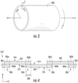
- FIG. 3 a schematic illustration is provided of an exemplary CMC component preform 300, e.g., a preform for forming a CMC component of turbofan engine 12 such as outer liner 84 of combustor 79.
- a CMC component preform 300 may have any appropriate shape for forming the resultant CMC component.
- the resultant CMC component may be axisymmetric, i.e., symmetric about an axis A-A, which may be longitudinal axis 13 of engine 12 in embodiments in which the resultant CMC component is a component of engine 12.
- the component preform 300 may be axisymmetric, e.g., as shown in FIG. 3 , preform 300 is symmetric about axis A-A.
- the CMC component may have other shapes or configurations, and preform 300 has a shape or contour appropriate for forming the CMC component.
- the preform 300 defines a radial direction R' that is orthogonal to axis A-A, as well as a circumferential direction C' that extends about axis A-A.
- the radial direction R' may be the radial direction R and the circumferential C' may be the circumferential direction C defined by engine 12.
- CMC component preform 300 may be made from a plurality of CMC plies, in particular, a plurality of first CMC plies 302 and a plurality of second CMC plies 304.
- the plurality of CMC plies are arranged such that second CMC plies 304 overlap first CMC plies 302. More specifically, each of first CMC plies 302 has ends 302a, 302b and each of second CMC plies 304 has ends 304a, 304b.
- Ends 304a, 304b of second CMC plies 304 overlap ends 302a, 302b of first CMC plies 302 such that each end 304a, 304b of each second CMC ply 304 overlies an end 304a or 304b of a first CMC ply 302.
- first CMC plies 302 are in contact with second CMC plies 304 along the ends of the plies 302
- second plies 304 are in contact with first plies 302 along the ends of the plies 304.
- first and second CMC plies 302, 304 define a plurality of overlap regions 306 that are spaced apart from one another along the circumferential direction C'. Further, the first and second CMC plies 302, 304 are arranged such that the ceramic fibers within each ply 302, 304 are oriented along the circumferential direction C'. That is, when laid up to form CMC component preform 300, the ceramic fibers within first CMC plies 302 are oriented in the same direction as the ceramic fibers within second CMC plies 304, and in the exemplary preform 300, the fibers of first and second plies 302, 304 are oriented along the circumferential direction C'.
- Overlapping first and second plies 302, 304 such that their ceramic fibers are overlapped in the circumferential or hoop direction can provide the structure needed to carry mechanical hoop strength in the resultant CMC component because the overlapped plies help ensure there are no breaks or cuts in the fibers extending along the circumferential direction C'.
- First and second CMC plies 302, 304 may be, e.g., plies pre-impregnated (prepreg) with matrix material and may be formed from prepreg tapes or the like.
- the CMC plies may be formed from a prepreg tape comprising a desired ceramic fiber reinforcement material, one or more precursors of the CMC matrix material, and organic resin binders.
- prepreg tapes can be formed by impregnating the reinforcement material with a slurry that contains the ceramic precursor(s) and binders.
- the slurry also may contain solvents for the binders that promote the fluidity of the slurry to enable impregnation of the fiber reinforcement material, as well as one or more particulate fillers intended to be present in the ceramic matrix of the CMC component, e.g., silicon and/or SiC powders in the case of a Si-SiC matrix.
- Preferred materials for the precursor will depend on the particular composition desired for the ceramic matrix of the CMC component.
- the precursor material may be SiC powder and/or one or more carbon-containing materials if the desired matrix material is SiC; notable carbon-containing materials include carbon black, phenolic resins, and furanic resins, including furfuryl alcohol (C 4 H 3 OCH 2 OH).
- the plurality of CMC plies 302, 304 may formed in other ways as well.
- each first CMC ply 302 has an inner surface 310 and an outer surface 312, and each second CMC ply 304 has an inner surface 314 and an outer surface 316. As illustrated in FIG.
- inner surface 314 of second ply 304 contacts outer surface 312 of first ply 302 along the contact length 308 at ends 304b, 302a and 304a, 302b such that the ends 304a, 304b of second ply 304 overlap the ends 302a, 302b of first ply 302.
- Each of the overlapping ends defines an overlap region 306, which has a width equal to the contact length 308 over which the ends 304b, 302a and 304a, 302b are in contact.
- first CMC plies 302 and second CMC plies 304 are overlapped such that the plurality of CMC plies 302, 304 extends along the circumferential direction C'.
- overlapping the ends of adjacent plies 302, 304 when CMC component preform 300 undergoes processing, e.g., to debulk and densify the CMC material as described below, a continuous ring of ceramic fibers may be oriented along the circumferential direction C', which helps to impart hoop strength to the resultant CMC component.
- each contact length 308, and accordingly, the width of each overlap region 306, need not be equal. However, each contact length 308 should be a sufficient length to ensure first plies 302 securely join with second plies 304 to form the continual ring of fibers along the circumferential direction C'.
- Overlapped first and second CMC plies 302, 304 define a layer 318 of CMC plies, and a plurality of layers 318 may be used to form CMC component preform 300.
- the plurality of CMC plies may be arranged in a first layer 318a, a second layer 318b, a third layer 318c, a fourth layer 318d, and a fifth layer 318e.
- a layer of axial CMC plies 320 is disposed between each layer 318 of first and second plies 302, 304.
- Axial plies 320 have ceramic fibers that extend generally axially within CMC component preform 300, i.e., the fibers extend generally parallel to axis A-A, about which preform 300 is symmetric.
- component preform 300 is an outer liner preform for forming outer liner 84 of engine 12
- axis A-A may be longitudinal centerline 13 of engine 12 or axis A-A may be parallel to longitudinal centerline 13.
- axial plies 320 may be laid up such that butt joints are formed between adjacent axial plies 320.
- adjacent axial plies 320 may be butted up against one another along their edges such that, unlike first and second CMC plies 302, 304, an axial CMC ply 320 does not overlap an adjacent axial ply 320, although adjacent axial plies 320 may be in contact with one another.
- each layer 318 of first and second CMC plies 302, 304 defines a plurality of overlap regions 306. More particularly, first layer 318a of CMC plies defines first overlap regions 306a, second layer 318b of CMC plies defines second overlap regions 306b, third layer 318c of CMC plies defines third overlap regions 306c, fourth layer 318d of CMC plies defines fourth overlap regions 306d, and fifth layer 318e of CMC plies defines fifth overlap regions 306e. Each layer 318 is positioned such that no two overlap regions 306 are radially aligned.
- second layer 318b is positioned with respect to first layer 318a such that second overlap regions 306b are offset from first overlap regions 306a along the circumferential direction C'. That is, none of the plurality of second overlap regions 306b is radially aligned with a first overlap region 306a.
- second layer 318b is positioned with respect to third, fourth, and fifth layers 318c, 318d, 318e such that second overlap regions 306b also are offset from third overlap regions 306c, fourth overlap regions 306d, and fifth overlap regions 306e along the circumferential direction C'. More specifically, each layer 318 is positioned with respect to the other layers 318 such that no overlap region 306 is radially aligned with another overlap region 306.
- FIG. 5 is provided by way of example only.
- layers 318 may be circumferentially and/or radially arranged in any order, including but not limited to the order shown in FIG. 5 .
- layers 318 are positioned such that no overlap region 306 is radially aligned with another overlap region 306.
- the CMC component preform 300 may include any suitable number of layers 318 with any suitable number of axial plies 320 between the layers 318.
- the plurality of CMC plies may be laid up on a layup tool 324 to form CMC component preform 300.
- tool 324 may be generally cylindrical in shape with an inner surface 326 and an outer surface 328.
- the CMC plies may be laid up on or against the generally cylindrical inner surface 326 of tool 324 to form a generally cylindrical, axisymmetric CMC component preform 300.
- each successive layer 318 of first and second CMC plies 302, 304 may be positioned radially inward with respect to the preceding layer 318.
- tool 324 may have any appropriate shape or configuration for laying up the plurality of CMC plies to define the shape or contour of CMC component preform 300, and the plurality of CMC plies 302, 304 may be laid up on inner surface 326 or outer surface 328 of tool 324 as appropriate.
- outer liner 84 is a CMC body 330 that is symmetric about longitudinal centerline 13 of engine 12, i.e., centerline 13 is the axis of symmetry for CMC body 330.
- the CMC body 330 defines the circumferential direction C that extends about the centerline 13, as well as radial direction R, which is orthogonal to centerline 13.
- the CMC body 330 is formed from a plurality of CMC plies 302, 304, 320 as described above.
- first and second CMC plies 302, 304 are laid up on a layup tool to define a generally smooth outer surface 96 of outer liner 84/CMC body 330. Further, the ends of a plurality of first CMC plies 302 and second CMC plies 304 are overlapped to define a plurality of overlap regions 306. Each overlap region 306 formed between contacting, overlapped plies 302, 304 is offset along the circumferential direction C such that no two overlap regions 306 are aligned along any radial line 322 drawn through longitudinal centerline 13. That is, any radial line 322 drawn through centerline 13 passes through only one overlap region 306. Further, as described above, each of first and second CMC plies 302, 304 comprises a plurality of ceramic fibers that are oriented substantially along one direction.
- the CMC plies 302, 304 forming CMC body 330 are positioned such that the ceramic fibers of first and second CMC plies 302, 304 are oriented along the circumferential direction C.
- overlapping ends of the plurality of first and second CMC plies 302, 304 which may be arranged in a plurality of layers 318 with axial plies 320 disposed between each layer 318 as previously discussed, forms a continuous ring of ceramic fibers in the circumferential direction C.
- the inner surface 94 of outer liner 84 generally is smooth and the CMC body 330 defining outer liner 84 has a substantially uniform thickness. More particularly, overlapping plies are not built up along the radial direction R, which could result in a liner 84 having one or more sections that are thicker than other sections of the liner such that the liner does not have a uniform thickness. Rather, the overlap regions 306 are distributed throughout the component such that liner 84 has a substantially uniform thickness and a generally smooth surface opposite the tooled surface, which is also a generally smooth surface if the tool on which the plies were laid up is substantially smooth.
- outer liner 84 properly interface with interfacing components such as outer dome section 104 and/or outer piston ring seal 118 as described above, as well as provide a smooth flow path for combustion gases 66.
- FIG. 6 depicts outer liner 84, it should be appreciated that inner liner 82 or any other appropriate component of engine 12 may be formed in substantially the same manner as the depicted outer liner 84 such that outer liner 84, inner liner 82, or other CMC component of engine 12 has a substantially uniform thickness.
- other components that are made using CMC materials, particularly axisymmetric CMC components may be formed as described with respect to outer liner 84.
- FIG. 7 provides a flow diagram illustrating a method 800 for forming a CMC component according to an exemplary embodiment of the present subject matter.
- the CMC component may be outer liner 84 for combustor 79 of gas turbine engine 12.
- a plurality of plies of a CMC material for forming the CMC component may be laid up to form CMC component preform 300 having a desired shape or contour.
- the desired shape of CMC component preform 300 may be a desired shape or contour of the resultant CMC component.
- the plies may be laid up to define a shape of CMC component preform 300 that is the shape of outer liner 84.
- the plurality of CMC plies 302, 304, 320 forming preform 300 may be laid up on layup tool 324 or may be laid up on another appropriate device for supporting the plies and/or for defining the desired shape.
- laying up the plurality of first and second CMC plies 302, 304 may comprise orienting the ceramic fibers of the CMC plies 302, 304 along the circumferential direction C', as shown at 802a in FIG. 7 . Further, as shown at 802b, laying up first and second CMC plies 302, 304 may include overlapping ends of plies 302, 304 to form a plurality of overlap regions 306. Overlapping ends of the plurality of CMC plies includes positioning ends 302a, 302b of the plurality of first CMC plies 302 in contact with ends 304a, 304b of the plurality of second CMC plies 304.
- each end of each second CMC ply 304 may be positioned to contact an end of a first CMC ply 302 over contact length 308.
- Each contact length 308 defines the width of the corresponding overlap region 306.
- plies 302, 304 may be laid up in a plurality of layers 318, each layer having a plurality of overlapped first and second CMC plies 302, 304 and, thus, a plurality of overlap regions 306.
- laying up plies 302, 304 in layers 318 further may comprise offsetting overlap regions 306 of each layer 318 such that any radial line 322 drawn through axis A-A of CMC component preform 300 does not pass through more than one overlap region 306.
- laying up the plurality of CMC plies may comprise laying up axial plies 320 between layers 318 of first and second plies 302, 304.
- layers 318 of first and second plies 302, 304 may be alternated with layers of axial plies 320. More particularly, layers 318 of plies 302, 304 are laid up to alternate with layers of axial plies 320 and to offset overlap regions 306 of layers 318 along the circumferential direction C' such that any radial line 322 drawn through axis A-A and the layup passes through the same number of plies 302, 304, 320 and passes through only one overlap region 306.
- the plies may be processed, e.g., compacted and cured in an autoclave, as shown at 804 in FIG. 7 .
- the plies form a green state CMC component, e.g., a green state CMC outer liner 84.
- the green state CMC component is a single piece component, i.e., curing plies 302, 304, 320 joins the plies to produce a CMC component formed from a continuous piece of CMC material.
- the green state component then may undergo firing (or burn-off) and densification, illustrated at 806 and 808 in FIG. 7 , to produce a final CMC component.
- the green state component is placed in a furnace with silicon to burn off any mandrel-forming materials and/or solvents used in forming the CMC plies 302, 304, 320, to decompose binders in the solvents, and to convert a ceramic matrix precursor of the plies into the ceramic material of the matrix of the CMC component.
- the silicon melts and infiltrates any porosity created with the matrix as a result of the decomposition of the binder during burn-off/firing; the melt infiltration of the CMC component with silicon densifies the CMC component.
- densification may be performed using any known densification technique including, but not limited to, Silcomp, melt-infiltration (MI), chemical vapor infiltration (CVI), polymer infiltration and pyrolysis (PIP), and oxide/oxide processes.
- densification and firing may be conducted in a vacuum furnace or an inert atmosphere having an established atmosphere at temperatures above 1200° C to allow silicon or another appropriate material or materials to melt-infiltrate into the component 100.
- the CMC component may be finish machined, if and as needed, and/or coated with an environmental barrier coating (EBC).
- EBC environmental barrier coating
- Method 800 is provided by way of example only.
- other processing cycles e.g., utilizing other known methods or techniques for compacting and/or curing CMC plies
- the CMC component may be post-processed or densified using any appropriate means.
- any combinations of these or other known processes may be used as well.
- a material other than a CMC material may be used to form the component, and such embodiments may include laying up plies of the other material by overlapping and offsetting the plies as described above.
- Any appropriate processing cycles and the like may be used to cure the component and thereby produce the final component, e.g., as described with respect to method 700.
- This written description uses examples to disclose the invention, including the best mode, and also to enable any person skilled in the art to practice the invention, including making and using any devices or systems and performing any incorporated methods.
- the patentable scope of the invention is defined by the claims.
Landscapes
- Engineering & Computer Science (AREA)
- Chemical & Material Sciences (AREA)
- Mechanical Engineering (AREA)
- Combustion & Propulsion (AREA)
- General Engineering & Computer Science (AREA)
- Composite Materials (AREA)
- Robotics (AREA)
- Ceramic Engineering (AREA)
- Turbine Rotor Nozzle Sealing (AREA)
- Structures Of Non-Positive Displacement Pumps (AREA)
Description
- The present subject matter relates generally to axisymmetric components and, more particularly, to axisymmetric components and methods of forming axisymmetric components of gas turbine engines.
- A gas turbine engine generally includes a fan and a core arranged in flow communication with one another. Additionally, the core of the gas turbine engine general includes, in serial flow order, a compressor section, a combustion section, a turbine section, and an exhaust section. In operation, air is provided from the fan to an inlet of the compressor section where one or more axial compressors progressively compress the air until it reaches the combustion section. Fuel is mixed with the compressed air and burned within the combustion section to provide combustion gases. The combustion gases are routed from the combustion section to the turbine section. The flow of combustion gases through the turbine section drives the turbine section and is then routed through the exhaust section, e.g., to atmosphere.
- More commonly, non-traditional high temperature materials, such as composite materials including ceramic matrix composite (CMC) materials, are being used for various components within gas turbine engines. For example, because CMC materials can withstand relatively extreme temperatures, there is particular interest in replacing components within the flow path of the combustion gases with CMC materials. However, typical methods of constructing components from plies of a material, such as plies of a CMC material, often result in components having local variations in thickness and/or unsmooth surfaces. Components that have a non-uniform thickness can negatively impact tolerances such that the components do not line up with or are difficult to line up with one or more interfacing components. Additionally, components with non-uniform thickness within the component present manufacturing difficulties. For example, local variations in component thickness can result in inconsistent machining of holes or apertures in the component.
FR2878608 A1 GB 2485215 A - Accordingly, a method for forming a component that reduces or eliminates variations in component thickness would be desirable. In particular, a method for forming an axisymmetric component that reduces or eliminates variations in component thickness while providing a component having hoop strength would be advantageous. Axisymmetric components having a substantially uniform thickness throughout the component also would be useful.
- Aspects and advantages of the invention will be set forth in part in the following description, or may be obvious from the description, or may be learned through practice of the invention.
- In one exemplary aspect of the present subject matter, a method for forming a component according to claim 1 is provided.
- In another exemplary aspect of the present subject matter, a component according to claim 8 is provided.
- These and other features, aspects and advantages of the present invention will become better understood with reference to the following description and appended claims. The accompanying drawings, which are incorporated in and constitute a part of this specification, illustrate embodiments of the invention and, together with the description, serve to explain the principles of the invention.
- A full and enabling disclosure of the present invention, including the best mode thereof, directed to one of ordinary skill in the art, is set forth in the specification, which makes reference to the appended figures, in which:
-
FIG. 1 is a schematic cross-sectional view of an exemplary gas turbine engine according to various embodiments of the present subject matter. -
FIG. 2 is a schematic side view of a combustion section and a turbine section of the exemplary gas turbine engine ofFIG. 1 . -
FIG. 3 is a schematic side view of a CMC component preform in accordance with an exemplary embodiment of the present subject matter. -
FIG. 4 is a schematic view of a plurality of CMC plies in accordance with an exemplary embodiment of the present subject matter. -
FIG. 5 is a schematic view of a plurality of CMC plies forming the CMC component preform ofFIG. 3 in accordance with an exemplary embodiment of the present subject matter. -
FIG. 6 is a cross-sectional view of an outer liner of a combustor of the gas turbine engine ofFIG. 2 , formed in accordance with an exemplary embodiment of the present subject matter. -
FIG. 7 is a flow diagram of a method for forming a CMC component in accordance with an exemplary embodiment of the present subject matter. - Reference will now be made in detail to present embodiments of the invention, one or more examples of which are illustrated in the accompanying drawings. The detailed description uses numerical and letter designations to refer to features in the drawings. Like or similar designations in the drawings and description have been used to refer to like or similar parts of the invention. As used herein, the terms "first", "second", and "third" may be used interchangeably to distinguish one component from another and are not intended to signify location or importance of the individual components. The terms "upstream" and "downstream" refer to the relative direction with respect to fluid flow in a fluid pathway. For example, "upstream" refers to the direction from which the fluid flows, and "downstream" refers to the direction to which the fluid flows.
- Referring now to the drawings, wherein identical numerals indicate the same elements throughout the figures,
FIG. 1 is a schematic cross-sectional view of a turbomachine in accordance with an exemplary embodiment of the present disclosure. More particularly, for the embodiment ofFIG. 1 , the turbomachine is configured as a gas turbine engine, or rather as a high-bypassturbofan jet engine 12, referred to herein as "turbofan engine 12." As shown inFIG. 1 , theturbofan engine 12 defines an axial direction A (extending parallel to alongitudinal centerline 13 provided for reference), a radial direction R, and a circumferential direction C (FIG. 6 ), i.e., a direction extending about the axial direction A. In general, the turbofan 10 includes afan section 14 and acore turbine engine 16 disposed downstream from thefan section 14. - The exemplary
core turbine engine 16 depicted generally includes a substantially tubularouter casing 18 that defines anannular inlet 20. Theouter casing 18 encases and thecore turbine engine 16 includes, in serial flow relationship, a compressor section including a booster or low pressure (LP)compressor 22 and a high pressure (HP)compressor 24; acombustion section 26; a turbine section including a high pressure (HP)turbine 28 and a low pressure (LP)turbine 30; and a jetexhaust nozzle section 32. A high pressure (HP) shaft orspool 34 drivingly connects the HPturbine 28 to the HPcompressor 24. A low pressure (LP) shaft orspool 36 drivingly connects theLP turbine 30 to theLP compressor 22. Accordingly, theLP shaft 36 and HPshaft 34 are each rotary components, rotating about the axial direction A during operation of theturbofan engine 12. - Referring still to the embodiment of
FIG. 1 , thefan section 14 includes afan 38 having a plurality offan blades 40 coupled to adisk 42 in a spaced apart manner. As depicted, thefan blades 40 extend outwardly fromdisk 42 generally along the radial direction R. Thefan blades 40 anddisk 42 are together rotatable about thelongitudinal axis 13 byLP shaft 36. More particularly, the fan section includes a fan shaft rotatable by theLP shaft 36. Accordingly, the fan shaft may also be considered a rotary component and is similarly supported by one or more bearings. - Referring still to the exemplary embodiment of
FIG. 1 , thedisk 42 is covered by afront hub 48 aerodynamically contoured to promote an airflow through the plurality offan blades 40.Front hub 48 may rotate withfan 38 aboutlongitudinal centerline 13. Additionally, theexemplary fan section 14 includes an annular fan casing orouter nacelle 50 that circumferentially surrounds thefan 38 and/or at least a portion of thecore turbine engine 16. Theexemplary nacelle 50 is supported relative to thecore turbine engine 16 by a plurality of circumferentially-spacedoutlet guide vanes 52. Moreover, adownstream section 54 of thenacelle 50 extends over an outer portion of thecore turbine engine 16 so as to define abypass airflow passage 56 therebetween. - During operation of the
turbofan engine 12, a volume ofair 58 enters the turbofan 10 through an associatedinlet 60 of thenacelle 50 and/orfan section 14. As the volume ofair 58 passes across thefan blades 40, afirst portion 62 of theair 58 is directed or routed into thebypass airflow passage 56 and asecond portion 64 of theair 58 is directed or routed into thecore air flowpath 37, or more specifically into theLP compressor 22. The ratio between thefirst portion 62 of air and thesecond portion 64 of air is commonly known as a bypass ratio. The pressure of thesecond portion 64 of air is then increased as it is routed through the high pressure (HP)compressor 24 and into thecombustion section 26, where it is mixed with fuel and burned to providecombustion gases 66. - The
combustion gases 66 are routed through theHP turbine 28 where a portion of thermal and/or kinetic energy from thecombustion gases 66 is extracted via sequential stages of HP turbine stator vanes 68 that are coupled to theouter casing 18 and HPturbine rotor blades 70 that are coupled to the HP shaft orspool 34, thus causing the HP shaft orspool 34 to rotate, thereby supporting operation of theHP compressor 24. Thecombustion gases 66 are then routed through theLP turbine 30 where a second portion of thermal and kinetic energy is extracted from thecombustion gases 66 via sequential stages of LPturbine stator vanes 72 that are coupled to theouter casing 18 and LPturbine rotor blades 74 that are coupled to the LP shaft orspool 36, thus causing the LP shaft orspool 36 to rotate, thereby supporting operation of theLP compressor 22 and/or rotation of thefan 38. - The
combustion gases 66 are subsequently routed through the jetexhaust nozzle section 32 of thecore turbine engine 16 to provide propulsive thrust. Simultaneously, the pressure of thefirst portion 62 ofair 58 is substantially increased as thefirst portion 62 of air is routed through thebypass airflow passage 56 before it is exhausted from a fannozzle exhaust section 76 of the turbofan 10, also providing propulsive thrust. TheHP turbine 28, theLP turbine 30, and the jetexhaust nozzle section 32 at least partially define ahot gas path 78 for routing thecombustion gases 66 through thecore turbine engine 16. - It should be appreciated that the
exemplary turbofan engine 12 depicted inFIG. 1 is by way of example only. In other exemplary embodiments, theturbofan engine 12 may have any other suitable configuration. - Referring now to
FIG. 2 , a schematic, cross-sectional view is provided of a combustor assembly 79 according to an exemplary embodiment of the present subject matter. More particularly,FIG. 2 provides a side, cross-sectional view of an exemplary combustor assembly 79, which may, for example, be positioned in thecombustion section 26 of theexemplary turbofan engine 12 ofFIG. 1 . - Combustor assembly 79 depicted in
FIG. 2 generally includes acombustion chamber 80 defined by aninner liner 82 and anouter liner 84, e.g.,combustion liners combustion chamber 80 therebetween.Combustion liners forward end 86 to anaft end 88.Inner liner 82 generally defines ahot side 90 exposed to and defining in part a portion of thecore air flowpath 37 extending through thecombustion chamber 80.Inner liner 82 further defines acold side 92 oppositehot side 90. Similarly,outer liner 84 also defines ahot side 94 exposed to and defining in part a portion of thecore air flowpath 37 extending through thecombustion chamber 80, andouter liner 84 further defines acold side 96 oppositehot side 94. - The inner and
outer liners annular dome 100 at theforward end 86 of combustor assembly 79. More particularly,annular dome 100 includes aninner dome section 102 attached toinner liner 82 and anouter dome section 104 attached toouter liner 84. The inner andouter dome sections outer dome sections slot 106 for receipt ofinner liner 82 andouter liner 84, respectively. - The combustor assembly 79 further includes a plurality of
fuel air mixers 108 spaced along the circumferential direction C and positioned at least partially within theannular dome 100. More particularly, the plurality offuel air mixers 108 are disposed at least partially betweenouter dome section 104 andinner dome section 102 along the radial direction R. Compressed air from the compressor section of theturbofan engine 12 flows into or through thefuel air mixers 108, where the compressed air is mixed with fuel and ignited to create thecombustion gases 66 within thecombustion chamber 80. The inner andouter dome sections fuel air mixers 108. For example,inner dome section 102 includes aninner cowl 110, andouter dome section 104 similarly includes anouter cowl 112. The inner andouter cowls fuel air mixers 108. - In certain exemplary embodiments, the
inner dome section 102 withinner cowl 110 may be formed integrally as a single annular component, and similarly, theouter dome section 104 withouter cowl 112 also may be formed integrally as a single annular component. It should be appreciated, however, that in other exemplary embodiments, theinner dome section 102 and/or theouter dome section 104 alternatively may be formed by one or more components being joined in any suitable manner. For example, with reference to theouter dome section 104, in certain exemplary embodiments,outer cowl 112 may be formed separately fromouter dome section 104 and attached toouter dome section 104 using, e.g., a welding process. Additionally or alternatively, theinner dome section 102 may have a similar configuration. - Referring still to
FIG. 2 , the exemplary combustor assembly 79 further includes aheat shield 114 positioned around thefuel air mixer 108 as depicted. Theexemplary heat shield 114, for the embodiment depicted, is attached to and extends between inner andouter dome sections heat shield 114 is configured to protect certain components of theturbofan engine 12 from the relatively extreme temperatures of thecombustion chamber 80. - Keeping with
FIG. 2 , combustor assembly 79 at theaft end 88 includes an inner piston ring seal 116 atinner liner 82 and an outerpiston ring seal 118 atouter liner 84. The inner piston ring seal 116 is attached to an innerpiston ring holder 120 extending from and attached to aninner casing 122. Similarly, the outerpiston ring seal 118 is attached to an outerpiston ring holder 124 extending from and attached to an outer casing 126. Innerpiston ring holder 120 and outerpiston ring holder 124 are configured to accommodate an expansion of theinner liner 82 and theouter liner 84 generally along the axial direction A, as well as generally along the radial direction R. To allow for a relative thermal expansion between theouter liner 84 and theouter dome section 104, as well as between theinner liner 82 and theinner dome section 102, a plurality of mountingassemblies 130 are used to attachouter liner 84 toouter dome section 104 andinner liner 82 toinner dome section 104. More particularly, the mountingassemblies 130 attach the forward end ofouter liner 84 toouter dome section 104 within theslot 106 ofouter dome section 104 and the forward end ofinner liner 82 toinner dome section 102 within theslot 122 ofinner dome section 102. As further described herein, when formed from CMC materials, inner andouter liners slots 122 ofdome sections outer liners - Further, as is discussed above, the
combustion gases 66 flow from thecombustion chamber 80 into and through the turbine section of theturbofan engine 12, where a portion of thermal and/or kinetic energy from thecombustion gases 66 is extracted via sequential stages of turbine stator vanes and turbine rotor blades. A stage one (1)stator vane 128 is depicted schematically inFIG. 2 , aft of the combustor assembly 79. - In some embodiments, components of
turbofan engine 12, particularly components withinhot gas path 78, may comprise a ceramic matrix composite (CMC) material, which is a non-metallic material having high temperature capability. For the depicted embodiment,inner liner 82 andouter liner 84 of combustor 79 are each formed of a CMC material. Exemplary CMC materials utilized for such components may include silicon carbide, silicon, silica, or alumina matrix materials and combinations thereof. Ceramic fibers may be embedded within the matrix, such as oxidation stable reinforcing fibers including monofilaments like sapphire and silicon carbide (e.g., Textron's SCS-6), as well as rovings and yarn including silicon carbide (e.g., Nippon Carbon's NICALON®, Ube Industries' TYRANNO®, and Dow Corning's SYLRAMIC®), alumina silicates (e.g., Nextel's 440 and 480), and chopped whiskers and fibers (e.g., Nextel's 440 and SAFFIL®), and optionally ceramic particles (e.g., oxides of Si, Al, Zr, Y, and combinations thereof) and inorganic fillers (e.g., pyrophyllite, wollastonite, mica, talc, kyanite, and montmorillonite). As further examples, the CMC materials may also include silicon carbide (SiC) or carbon fiber cloth. Of course, other appropriate materials, including other composite materials, may be used to form the components ofengine 12, including the components withinhot gas path 78 such as inner andouter combustion liners - Turning to
FIG. 3 , a schematic illustration is provided of an exemplaryCMC component preform 300, e.g., a preform for forming a CMC component ofturbofan engine 12 such asouter liner 84 of combustor 79. Although the schematic illustration ofFIG. 3 depicts theCMC component preform 300 as generally cylindrical, it will be appreciated thatpreform 300 may have any appropriate shape for forming the resultant CMC component. In particular embodiments, the resultant CMC component may be axisymmetric, i.e., symmetric about an axis A-A, which may belongitudinal axis 13 ofengine 12 in embodiments in which the resultant CMC component is a component ofengine 12. Accordingly, to form an axisymmetric CMC component, thecomponent preform 300 may be axisymmetric, e.g., as shown inFIG. 3 , preform 300 is symmetric about axis A-A. However, in other embodiments, the CMC component may have other shapes or configurations, and preform 300 has a shape or contour appropriate for forming the CMC component. As further shown inFIG. 3 , thepreform 300 defines a radial direction R' that is orthogonal to axis A-A, as well as a circumferential direction C' that extends about axis A-A. In some embodiments wherepreform 300 results in a component ofengine 12, the radial direction R' may be the radial direction R and the circumferential C' may be the circumferential direction C defined byengine 12. - Referring now to
FIG. 4 ,CMC component preform 300 may be made from a plurality of CMC plies, in particular, a plurality of first CMC plies 302 and a plurality of second CMC plies 304. In the exemplary embodiment shown inFIG. 4 , the plurality of CMC plies are arranged such that second CMC plies 304 overlap first CMC plies 302. More specifically, each of first CMC plies 302 hasends ends Ends end end first CMC ply 302. By overlappingends ends plies 302, andsecond plies 304 are in contact withfirst plies 302 along the ends of theplies 304. The overlapping ends of first and second CMC plies 302, 304 define a plurality ofoverlap regions 306 that are spaced apart from one another along the circumferential direction C'. Further, the first and second CMC plies 302, 304 are arranged such that the ceramic fibers within eachply CMC component preform 300, the ceramic fibers within first CMC plies 302 are oriented in the same direction as the ceramic fibers within second CMC plies 304, and in theexemplary preform 300, the fibers of first andsecond plies second plies - First and second CMC plies 302, 304 may be, e.g., plies pre-impregnated (prepreg) with matrix material and may be formed from prepreg tapes or the like. For example, the CMC plies may be formed from a prepreg tape comprising a desired ceramic fiber reinforcement material, one or more precursors of the CMC matrix material, and organic resin binders. According to conventional practice, prepreg tapes can be formed by impregnating the reinforcement material with a slurry that contains the ceramic precursor(s) and binders. The slurry also may contain solvents for the binders that promote the fluidity of the slurry to enable impregnation of the fiber reinforcement material, as well as one or more particulate fillers intended to be present in the ceramic matrix of the CMC component, e.g., silicon and/or SiC powders in the case of a Si-SiC matrix. Preferred materials for the precursor will depend on the particular composition desired for the ceramic matrix of the CMC component. For example, the precursor material may be SiC powder and/or one or more carbon-containing materials if the desired matrix material is SiC; notable carbon-containing materials include carbon black, phenolic resins, and furanic resins, including furfuryl alcohol (C4H3OCH2OH). Of course, the plurality of CMC plies 302, 304 may formed in other ways as well.
- Referring still to
FIG. 4 ,end 304b ofsecond plies 304 overlies or overlapsend 302a offirst plies 302 such that ends 304b, 302a are in contact for acontact length 308.End 304a ofsecond plies 304 overlies or overlapsend 302b offirst plies 302 such that ends 304a, 302b are in contact forcontact length 308. More particularly, each first CMC ply 302 has aninner surface 310 and anouter surface 312, and each second CMC ply 304 has aninner surface 314 and anouter surface 316. As illustrated inFIG. 4 ,inner surface 314 ofsecond ply 304 contactsouter surface 312 offirst ply 302 along thecontact length 308 atends ends second ply 304 overlap theends first ply 302. Each of the overlapping ends defines anoverlap region 306, which has a width equal to thecontact length 308 over which theends - Further, as depicted in
FIG. 4 , first CMC plies 302 and second CMC plies 304 are overlapped such that the plurality of CMC plies 302, 304 extends along the circumferential direction C'. By overlapping the ends ofadjacent plies CMC component preform 300 undergoes processing, e.g., to debulk and densify the CMC material as described below, a continuous ring of ceramic fibers may be oriented along the circumferential direction C', which helps to impart hoop strength to the resultant CMC component. Moreover, although shown as been substantially equal, eachcontact length 308, and accordingly, the width of each overlapregion 306, need not be equal. However, eachcontact length 308 should be a sufficient length to ensurefirst plies 302 securely join withsecond plies 304 to form the continual ring of fibers along the circumferential direction C'. - Overlapped first and second CMC plies 302, 304 define a
layer 318 of CMC plies, and a plurality oflayers 318 may be used to formCMC component preform 300. For example, as shown inFIG. 5 , the plurality of CMC plies may be arranged in a first layer 318a, asecond layer 318b, athird layer 318c, afourth layer 318d, and afifth layer 318e. A layer of axial CMC plies 320 is disposed between eachlayer 318 of first andsecond plies CMC component preform 300, i.e., the fibers extend generally parallel to axis A-A, about which preform 300 is symmetric. In embodiments in whichcomponent preform 300 is an outer liner preform for formingouter liner 84 ofengine 12, axis A-A may belongitudinal centerline 13 ofengine 12 or axis A-A may be parallel tolongitudinal centerline 13. Further,axial plies 320 may be laid up such that butt joints are formed between adjacentaxial plies 320. That is, adjacentaxial plies 320 may be butted up against one another along their edges such that, unlike first and second CMC plies 302, 304, an axial CMC ply 320 does not overlap an adjacentaxial ply 320, although adjacentaxial plies 320 may be in contact with one another. - Further, as illustrated in
FIG. 5 , eachlayer 318 of first and second CMC plies 302, 304 defines a plurality ofoverlap regions 306. More particularly, first layer 318a of CMC plies defines first overlap regions 306a,second layer 318b of CMC plies definessecond overlap regions 306b,third layer 318c of CMC plies definesthird overlap regions 306c,fourth layer 318d of CMC plies definesfourth overlap regions 306d, andfifth layer 318e of CMC plies definesfifth overlap regions 306e. Eachlayer 318 is positioned such that no two overlapregions 306 are radially aligned. For example,second layer 318b is positioned with respect to first layer 318a such thatsecond overlap regions 306b are offset from first overlap regions 306a along the circumferential direction C'. That is, none of the plurality ofsecond overlap regions 306b is radially aligned with a first overlap region 306a. Similarly,second layer 318b is positioned with respect to third, fourth, andfifth layers second overlap regions 306b also are offset fromthird overlap regions 306c,fourth overlap regions 306d, andfifth overlap regions 306e along the circumferential direction C'. More specifically, eachlayer 318 is positioned with respect to theother layers 318 such that nooverlap region 306 is radially aligned with anotheroverlap region 306. Accordingly, anyradial line 322 drawn throughlayers axial plies 320, which formCMC component preform 300, passes through the same number ofplies overlap region 306. - It will be appreciated that
FIG. 5 is provided by way of example only. In other embodiments, layers 318 may be circumferentially and/or radially arranged in any order, including but not limited to the order shown inFIG. 5 . However, regardless of the order in which the layers are arranged,layers 318 are positioned such that nooverlap region 306 is radially aligned with anotheroverlap region 306. Further, although illustrated inFIG. 5 as including fivelayers 318 with one layer ofaxial plies 320 betweenlayers 318, in other embodiments theCMC component preform 300 may include any suitable number oflayers 318 with any suitable number ofaxial plies 320 between thelayers 318. - Referring still to
FIG. 5 , it will be appreciated that the plurality of CMC plies may be laid up on alayup tool 324 to formCMC component preform 300. Although shown as generally linear in the schematic illustration ofFIG. 5 ,tool 324 may be generally cylindrical in shape with aninner surface 326 and anouter surface 328. In such embodiments, the CMC plies may be laid up on or against the generally cylindricalinner surface 326 oftool 324 to form a generally cylindrical, axisymmetricCMC component preform 300. As such, eachsuccessive layer 318 of first and second CMC plies 302, 304 may be positioned radially inward with respect to thepreceding layer 318. In other embodiments,tool 324 may have any appropriate shape or configuration for laying up the plurality of CMC plies to define the shape or contour ofCMC component preform 300, and the plurality of CMC plies 302, 304 may be laid up oninner surface 326 orouter surface 328 oftool 324 as appropriate. - Turning now to
FIG. 6 , a schematic cross-section view ofouter liner 84 ofFIG. 2 is provided. In the depicted exemplary embodiment of the present subject matter,outer liner 84 is aCMC body 330 that is symmetric aboutlongitudinal centerline 13 ofengine 12, i.e.,centerline 13 is the axis of symmetry forCMC body 330. TheCMC body 330 defines the circumferential direction C that extends about thecenterline 13, as well as radial direction R, which is orthogonal to centerline 13. TheCMC body 330 is formed from a plurality of CMC plies 302, 304, 320 as described above. More particularly, the CMC plies are laid up on a layup tool to define a generally smoothouter surface 96 ofouter liner 84/CMC body 330. Further, the ends of a plurality of first CMC plies 302 and second CMC plies 304 are overlapped to define a plurality ofoverlap regions 306. Eachoverlap region 306 formed between contacting, overlapped plies 302, 304 is offset along the circumferential direction C such that no two overlapregions 306 are aligned along anyradial line 322 drawn throughlongitudinal centerline 13. That is, anyradial line 322 drawn throughcenterline 13 passes through only oneoverlap region 306. Further, as described above, each of first and second CMC plies 302, 304 comprises a plurality of ceramic fibers that are oriented substantially along one direction. The CMC plies 302, 304 formingCMC body 330 are positioned such that the ceramic fibers of first and second CMC plies 302, 304 are oriented along the circumferential direction C. Thus, overlapping ends of the plurality of first and second CMC plies 302, 304, which may be arranged in a plurality oflayers 318 withaxial plies 320 disposed between eachlayer 318 as previously discussed, forms a continuous ring of ceramic fibers in the circumferential direction C. - Accordingly, by offsetting
overlap regions 306, theinner surface 94 ofouter liner 84 generally is smooth and theCMC body 330 definingouter liner 84 has a substantially uniform thickness. More particularly, overlapping plies are not built up along the radial direction R, which could result in aliner 84 having one or more sections that are thicker than other sections of the liner such that the liner does not have a uniform thickness. Rather, theoverlap regions 306 are distributed throughout the component such thatliner 84 has a substantially uniform thickness and a generally smooth surface opposite the tooled surface, which is also a generally smooth surface if the tool on which the plies were laid up is substantially smooth. The generally smooth surfaces and substantially uniform thickness can helpouter liner 84 properly interface with interfacing components such asouter dome section 104 and/or outerpiston ring seal 118 as described above, as well as provide a smooth flow path forcombustion gases 66. Further, whileFIG. 6 depictsouter liner 84, it should be appreciated thatinner liner 82 or any other appropriate component ofengine 12 may be formed in substantially the same manner as the depictedouter liner 84 such thatouter liner 84,inner liner 82, or other CMC component ofengine 12 has a substantially uniform thickness. Additionally or alternatively, other components that are made using CMC materials, particularly axisymmetric CMC components, may be formed as described with respect toouter liner 84. -
FIG. 7 provides a flow diagram illustrating amethod 800 for forming a CMC component according to an exemplary embodiment of the present subject matter. For example, the CMC component may beouter liner 84 for combustor 79 ofgas turbine engine 12. As shown at 802 inFIG. 7 , a plurality of plies of a CMC material for forming the CMC component may be laid up to formCMC component preform 300 having a desired shape or contour. The desired shape ofCMC component preform 300 may be a desired shape or contour of the resultant CMC component. As an example, the plies may be laid up to define a shape ofCMC component preform 300 that is the shape ofouter liner 84. As described above, the plurality of CMC plies 302, 304, 320 formingpreform 300 may be laid up onlayup tool 324 or may be laid up on another appropriate device for supporting the plies and/or for defining the desired shape. - Further, as described above, laying up the plurality of first and second CMC plies 302, 304 may comprise orienting the ceramic fibers of the CMC plies 302, 304 along the circumferential direction C', as shown at 802a in
FIG. 7 . Further, as shown at 802b, laying up first and second CMC plies 302, 304 may include overlapping ends ofplies overlap regions 306. Overlapping ends of the plurality of CMC plies includes positioning ends 302a, 302b of the plurality of first CMC plies 302 in contact withends contact length 308. Eachcontact length 308 defines the width of thecorresponding overlap region 306. By overlapping ends ofplies - Moreover, plies 302, 304 may be laid up in a plurality of
layers 318, each layer having a plurality of overlapped first and second CMC plies 302, 304 and, thus, a plurality ofoverlap regions 306. Referring still toFIG. 7 , as shown at 802c, laying upplies layers 318 further may comprise offsettingoverlap regions 306 of eachlayer 318 such that anyradial line 322 drawn through axis A-A ofCMC component preform 300 does not pass through more than oneoverlap region 306. Additionally, laying up the plurality of CMC plies may comprise laying upaxial plies 320 betweenlayers 318 of first andsecond plies second plies axial plies 320. More particularly, layers 318 ofplies axial plies 320 and to offsetoverlap regions 306 oflayers 318 along the circumferential direction C' such that anyradial line 322 drawn through axis A-A and the layup passes through the same number ofplies overlap region 306. - After the plurality of
plies FIG. 7 . After processing, the plies form a green state CMC component, e.g., a green state CMCouter liner 84. The green state CMC component is a single piece component, i.e., curing plies 302, 304, 320 joins the plies to produce a CMC component formed from a continuous piece of CMC material. The green state component then may undergo firing (or burn-off) and densification, illustrated at 806 and 808 inFIG. 7 , to produce a final CMC component. In an exemplary embodiment ofmethod 800, the green state component is placed in a furnace with silicon to burn off any mandrel-forming materials and/or solvents used in forming the CMC plies 302, 304, 320, to decompose binders in the solvents, and to convert a ceramic matrix precursor of the plies into the ceramic material of the matrix of the CMC component. The silicon melts and infiltrates any porosity created with the matrix as a result of the decomposition of the binder during burn-off/firing; the melt infiltration of the CMC component with silicon densifies the CMC component. However, densification may be performed using any known densification technique including, but not limited to, Silcomp, melt-infiltration (MI), chemical vapor infiltration (CVI), polymer infiltration and pyrolysis (PIP), and oxide/oxide processes. In one embodiment, densification and firing may be conducted in a vacuum furnace or an inert atmosphere having an established atmosphere at temperatures above 1200° C to allow silicon or another appropriate material or materials to melt-infiltrate into thecomponent 100. Optionally, as shown at 810 inFIG. 7 , after firing and densification the CMC component may be finish machined, if and as needed, and/or coated with an environmental barrier coating (EBC). -
Method 800 is provided by way of example only. For example, other processing cycles, e.g., utilizing other known methods or techniques for compacting and/or curing CMC plies, may be used. Further, the CMC component may be post-processed or densified using any appropriate means. Alternatively, any combinations of these or other known processes may be used as well. Moreover, in some embodiments, not encompassed by the wording of the claims, a material other than a CMC material may be used to form the component, and such embodiments may include laying up plies of the other material by overlapping and offsetting the plies as described above. Any appropriate processing cycles and the like may be used to cure the component and thereby produce the final component, e.g., as described with respect to method 700.
This written description uses examples to disclose the invention, including the best mode, and also to enable any person skilled in the art to practice the invention, including making and using any devices or systems and performing any incorporated methods. The patentable scope of the invention is defined by the claims.
Claims (10)
- A method for forming a component, the method comprising:
laying up a plurality of ceramic matrix composite, CMC, plies to form a CMC component preform (300), wherein the plurality of CMC plies comprises a plurality of first CMC plies and a plurality of second CMC plies, each of the first and second CMC plies comprising a plurality of ceramic fibers, the CMC component preform defining an axis of symmetry and a circumferential direction, wherein laying up the plurality of CMC plies includesoverlapping ends of the plurality of CMC plies, each overlapped end defining an overlap region (306), and characterized byoffsetting the overlap regions along the circumferential direction such that any radial line drawn from the axis of symmetry through the plurality of CMC plies passes through only one overlap region,wherein the first and the second CMC plies are arranged such that the ceramic fibers within each ply are oriented along the circumferential direction. - The method of claim 1, wherein each first CMC ply has two ends (302a, 302b) and each second CMC ply has two ends (304a, 304b), and wherein each end of each second CMC ply overlaps an end of a first CMC ply.
- The method of claim 1, wherein overlapping ends of the plurality of CMC plies comprises positioning ends (302a, 302b) of the plurality of first CMC plies in contact with ends (304a, 304b) of the plurality of second CMC plies.
- The method of claim 1, wherein the plurality of CMC plies includes a plurality of layers (318) of first CMC plies and second CMC plies, and wherein each layer defines a plurality of overlap regions (306).
- The method of claim 4, wherein offsetting the overlap regions (306) comprises offsetting the plurality of overlap regions from one another along the circumferential direction.
- The method of claim 4, wherein a row of axial plies (320) is disposed between each layer (318) of first CMC plies and second CMC plies.
- The method of claim 6, wherein offsetting the overlap regions (306) comprises offsetting the plurality of overlap regions along the circumferential direction such that any radial line drawn from the axis of symmetry through the CMC plies passes through the same number of first CMC plies (302), second CMC plies (304), and axial (320) plies.
- A component, comprising:a body (330), the body symmetric about an axis of symmetry, the body defining a circumferential direction about the axis of symmetry and a radial direction orthogonal to the axis of symmetry,wherein the body (330) is formed from a plurality of plies,wherein ends of the plurality of plies are overlapped to define a plurality of overlap regions (306), the overlap regions offset along the circumferential direction,wherein the plurality of plies comprises a plurality of first ceramic matrix composite (CMC) plies (302) and a plurality of second CMC plies (304), each of the first and second CMC plies comprising a plurality of ceramic fibers, characterized in that the ceramic fibers of the first and second CMC plies are oriented along the circumferential direction, andwherein the body has a substantially uniform thickness.
- The component of claim 8, wherein any radial line drawn from the axis of symmetry through the plurality of plies passes through only one overlap region.
- The component of claim 8, wherein the ends of the plurality of the first CMC plies are overlapped with ends of the plurality of the second CMC plies to form a continuous ring of ceramic fibers in the circumferential direction.
Applications Claiming Priority (2)
| Application Number | Priority Date | Filing Date | Title |
|---|---|---|---|
| US15/207,814 US10401030B2 (en) | 2016-07-12 | 2016-07-12 | Axisymmetric components and methods for forming axisymmetric components |
| PCT/US2017/040799 WO2018013393A1 (en) | 2016-07-12 | 2017-07-06 | Axisymmetric components and methods for forming axisymmetric components |
Publications (2)
| Publication Number | Publication Date |
|---|---|
| EP3484693A1 EP3484693A1 (en) | 2019-05-22 |
| EP3484693B1 true EP3484693B1 (en) | 2024-10-09 |
Family
ID=59381703
Family Applications (1)
| Application Number | Title | Priority Date | Filing Date |
|---|---|---|---|
| EP17742340.7A Active EP3484693B1 (en) | 2016-07-12 | 2017-07-06 | Axisymmetric components and methods for forming axisymmetric components |
Country Status (4)
| Country | Link |
|---|---|
| US (1) | US10401030B2 (en) |
| EP (1) | EP3484693B1 (en) |
| CN (1) | CN109414888B (en) |
| WO (1) | WO2018013393A1 (en) |
Families Citing this family (7)
| Publication number | Priority date | Publication date | Assignee | Title |
|---|---|---|---|---|
| US10974465B2 (en) | 2018-06-20 | 2021-04-13 | The Boeing Company | Method and system for generating a layup plan for forming a composite laminate |
| US11034100B2 (en) * | 2018-06-20 | 2021-06-15 | The Boeing Company | Automated manufacture of complex contoured composite parts |
| US11209166B2 (en) | 2018-12-05 | 2021-12-28 | General Electric Company | Combustor assembly for a turbine engine |
| US11047574B2 (en) | 2018-12-05 | 2021-06-29 | General Electric Company | Combustor assembly for a turbine engine |
| US12234986B2 (en) * | 2020-07-16 | 2025-02-25 | Rtx Corporation | Article and method for manufacturing an expanded combustor liner |
| US12472703B2 (en) * | 2022-01-07 | 2025-11-18 | The Boeing Company | Automated fiber placement of plies with staggering |
| US12292193B2 (en) * | 2023-06-28 | 2025-05-06 | Rtx Corporation | Combustor liner with pattern of voids in CMC fiber ply for cooling channels |
Family Cites Families (6)
| Publication number | Priority date | Publication date | Assignee | Title |
|---|---|---|---|---|
| US6851643B2 (en) * | 2003-01-27 | 2005-02-08 | Sonoco Development, Inc. | Spirally wound tube with enhanced inner diameter stiffness, and method of making same |
| FR2878608B1 (en) | 2004-11-29 | 2007-02-23 | Eads Space Transp Sas Soc Par | THERMAL PROTECTIVE COATING WITH LEFT ELEMENTARY PIECES AND METHOD OF MANUFACTURING THE SAME |
| US7550107B2 (en) * | 2005-07-25 | 2009-06-23 | Siemens Energy, Inc. | Method of forming CMC component |
| US7712487B2 (en) | 2006-09-13 | 2010-05-11 | Sonoco Development, Inc. | Spirally wound tube with voids and method for manufacturing the same |
| GB2485215B (en) | 2010-11-05 | 2013-12-25 | Gkn Aerospace Services Ltd | Laminate Structure |
| US10654246B2 (en) | 2012-04-28 | 2020-05-19 | General Electric Company | Composite article and methods therefor |
-
2016
- 2016-07-12 US US15/207,814 patent/US10401030B2/en active Active
-
2017
- 2017-07-06 WO PCT/US2017/040799 patent/WO2018013393A1/en not_active Ceased
- 2017-07-06 CN CN201780043324.5A patent/CN109414888B/en active Active
- 2017-07-06 EP EP17742340.7A patent/EP3484693B1/en active Active
Also Published As
| Publication number | Publication date |
|---|---|
| EP3484693A1 (en) | 2019-05-22 |
| US20180017258A1 (en) | 2018-01-18 |
| CN109414888A (en) | 2019-03-01 |
| WO2018013393A1 (en) | 2018-01-18 |
| US10401030B2 (en) | 2019-09-03 |
| CN109414888B (en) | 2021-08-27 |
Similar Documents
| Publication | Publication Date | Title |
|---|---|---|
| US11828199B2 (en) | Methods and assemblies for attaching airfoils within a flow path | |
| US11149569B2 (en) | Flow path assembly with airfoils inserted through flow path boundary | |
| US11391171B2 (en) | Methods and features for positioning a flow path assembly within a gas turbine engine | |
| US11143402B2 (en) | Unitary flow path structure | |
| US10401030B2 (en) | Axisymmetric components and methods for forming axisymmetric components | |
| US10378772B2 (en) | Combustor heat shield sealing | |
| US11846207B2 (en) | Nozzle assembly with alternating inserted vanes for a turbine engine | |
| US11384651B2 (en) | Methods and features for positioning a flow path inner boundary within a flow path assembly | |
| US10378770B2 (en) | Unitary flow path structure | |
| US10371383B2 (en) | Unitary flow path structure | |
| US20170370583A1 (en) | Ceramic Matrix Composite Component for a Gas Turbine Engine | |
| US20240117756A1 (en) | Cte matching hanger support for cmc structures | |
| US10370990B2 (en) | Flow path assembly with pin supported nozzle airfoils | |
| US10816199B2 (en) | Combustor heat shield and attachment features |
Legal Events
| Date | Code | Title | Description |
|---|---|---|---|
| STAA | Information on the status of an ep patent application or granted ep patent |
Free format text: STATUS: UNKNOWN |
|
| STAA | Information on the status of an ep patent application or granted ep patent |
Free format text: STATUS: THE INTERNATIONAL PUBLICATION HAS BEEN MADE |
|
| PUAI | Public reference made under article 153(3) epc to a published international application that has entered the european phase |
Free format text: ORIGINAL CODE: 0009012 |
|
| STAA | Information on the status of an ep patent application or granted ep patent |
Free format text: STATUS: REQUEST FOR EXAMINATION WAS MADE |
|
| 17P | Request for examination filed |
Effective date: 20190212 |
|
| AK | Designated contracting states |
Kind code of ref document: A1 Designated state(s): AL AT BE BG CH CY CZ DE DK EE ES FI FR GB GR HR HU IE IS IT LI LT LU LV MC MK MT NL NO PL PT RO RS SE SI SK SM TR |
|
| AX | Request for extension of the european patent |
Extension state: BA ME |
|
| DAV | Request for validation of the european patent (deleted) | ||
| DAX | Request for extension of the european patent (deleted) | ||
| STAA | Information on the status of an ep patent application or granted ep patent |
Free format text: STATUS: EXAMINATION IS IN PROGRESS |
|
| 17Q | First examination report despatched |
Effective date: 20220324 |
|
| GRAP | Despatch of communication of intention to grant a patent |
Free format text: ORIGINAL CODE: EPIDOSNIGR1 |
|
| STAA | Information on the status of an ep patent application or granted ep patent |
Free format text: STATUS: GRANT OF PATENT IS INTENDED |
|
| INTG | Intention to grant announced |
Effective date: 20240102 |
|
| GRAJ | Information related to disapproval of communication of intention to grant by the applicant or resumption of examination proceedings by the epo deleted |
Free format text: ORIGINAL CODE: EPIDOSDIGR1 |
|
| STAA | Information on the status of an ep patent application or granted ep patent |
Free format text: STATUS: EXAMINATION IS IN PROGRESS |
|
| INTC | Intention to grant announced (deleted) | ||
| GRAP | Despatch of communication of intention to grant a patent |
Free format text: ORIGINAL CODE: EPIDOSNIGR1 |
|
| STAA | Information on the status of an ep patent application or granted ep patent |
Free format text: STATUS: GRANT OF PATENT IS INTENDED |
|
| INTG | Intention to grant announced |
Effective date: 20240508 |
|
| GRAS | Grant fee paid |
Free format text: ORIGINAL CODE: EPIDOSNIGR3 |
|
| GRAA | (expected) grant |
Free format text: ORIGINAL CODE: 0009210 |
|
| STAA | Information on the status of an ep patent application or granted ep patent |
Free format text: STATUS: THE PATENT HAS BEEN GRANTED |
|
| AK | Designated contracting states |
Kind code of ref document: B1 Designated state(s): AL AT BE BG CH CY CZ DE DK EE ES FI FR GB GR HR HU IE IS IT LI LT LU LV MC MK MT NL NO PL PT RO RS SE SI SK SM TR |
|
| REG | Reference to a national code |
Ref country code: CH Ref legal event code: EP |
|
| P01 | Opt-out of the competence of the unified patent court (upc) registered |
Free format text: CASE NUMBER: APP_51241/2024 Effective date: 20240910 |
|
| REG | Reference to a national code |
Ref country code: DE Ref legal event code: R096 Ref document number: 602017085358 Country of ref document: DE |
|
| REG | Reference to a national code |
Ref country code: IE Ref legal event code: FG4D |
|
| REG | Reference to a national code |
Ref country code: LT Ref legal event code: MG9D |
|
| REG | Reference to a national code |
Ref country code: NL Ref legal event code: MP Effective date: 20241009 |
|
| REG | Reference to a national code |
Ref country code: AT Ref legal event code: MK05 Ref document number: 1730144 Country of ref document: AT Kind code of ref document: T Effective date: 20241009 |
|
| PG25 | Lapsed in a contracting state [announced via postgrant information from national office to epo] |
Ref country code: NL Free format text: LAPSE BECAUSE OF FAILURE TO SUBMIT A TRANSLATION OF THE DESCRIPTION OR TO PAY THE FEE WITHIN THE PRESCRIBED TIME-LIMIT Effective date: 20241009 |
|
| PG25 | Lapsed in a contracting state [announced via postgrant information from national office to epo] |
Ref country code: NL Free format text: LAPSE BECAUSE OF FAILURE TO SUBMIT A TRANSLATION OF THE DESCRIPTION OR TO PAY THE FEE WITHIN THE PRESCRIBED TIME-LIMIT Effective date: 20241009 |
|
| PG25 | Lapsed in a contracting state [announced via postgrant information from national office to epo] |
Ref country code: IS Free format text: LAPSE BECAUSE OF FAILURE TO SUBMIT A TRANSLATION OF THE DESCRIPTION OR TO PAY THE FEE WITHIN THE PRESCRIBED TIME-LIMIT Effective date: 20250209 Ref country code: PT Free format text: LAPSE BECAUSE OF FAILURE TO SUBMIT A TRANSLATION OF THE DESCRIPTION OR TO PAY THE FEE WITHIN THE PRESCRIBED TIME-LIMIT Effective date: 20250210 Ref country code: HR Free format text: LAPSE BECAUSE OF FAILURE TO SUBMIT A TRANSLATION OF THE DESCRIPTION OR TO PAY THE FEE WITHIN THE PRESCRIBED TIME-LIMIT Effective date: 20241009 |
|
| PG25 | Lapsed in a contracting state [announced via postgrant information from national office to epo] |
Ref country code: FI Free format text: LAPSE BECAUSE OF FAILURE TO SUBMIT A TRANSLATION OF THE DESCRIPTION OR TO PAY THE FEE WITHIN THE PRESCRIBED TIME-LIMIT Effective date: 20241009 |
|
| PG25 | Lapsed in a contracting state [announced via postgrant information from national office to epo] |
Ref country code: BG Free format text: LAPSE BECAUSE OF FAILURE TO SUBMIT A TRANSLATION OF THE DESCRIPTION OR TO PAY THE FEE WITHIN THE PRESCRIBED TIME-LIMIT Effective date: 20241009 |
|
| PG25 | Lapsed in a contracting state [announced via postgrant information from national office to epo] |
Ref country code: ES Free format text: LAPSE BECAUSE OF FAILURE TO SUBMIT A TRANSLATION OF THE DESCRIPTION OR TO PAY THE FEE WITHIN THE PRESCRIBED TIME-LIMIT Effective date: 20241009 |
|
| PG25 | Lapsed in a contracting state [announced via postgrant information from national office to epo] |
Ref country code: NO Free format text: LAPSE BECAUSE OF FAILURE TO SUBMIT A TRANSLATION OF THE DESCRIPTION OR TO PAY THE FEE WITHIN THE PRESCRIBED TIME-LIMIT Effective date: 20250109 |
|
| PG25 | Lapsed in a contracting state [announced via postgrant information from national office to epo] |
Ref country code: LV Free format text: LAPSE BECAUSE OF FAILURE TO SUBMIT A TRANSLATION OF THE DESCRIPTION OR TO PAY THE FEE WITHIN THE PRESCRIBED TIME-LIMIT Effective date: 20241009 Ref country code: GR Free format text: LAPSE BECAUSE OF FAILURE TO SUBMIT A TRANSLATION OF THE DESCRIPTION OR TO PAY THE FEE WITHIN THE PRESCRIBED TIME-LIMIT Effective date: 20250110 Ref country code: AT Free format text: LAPSE BECAUSE OF FAILURE TO SUBMIT A TRANSLATION OF THE DESCRIPTION OR TO PAY THE FEE WITHIN THE PRESCRIBED TIME-LIMIT Effective date: 20241009 |
|
| PG25 | Lapsed in a contracting state [announced via postgrant information from national office to epo] |
Ref country code: PL Free format text: LAPSE BECAUSE OF FAILURE TO SUBMIT A TRANSLATION OF THE DESCRIPTION OR TO PAY THE FEE WITHIN THE PRESCRIBED TIME-LIMIT Effective date: 20241009 |
|
| PG25 | Lapsed in a contracting state [announced via postgrant information from national office to epo] |
Ref country code: RS Free format text: LAPSE BECAUSE OF FAILURE TO SUBMIT A TRANSLATION OF THE DESCRIPTION OR TO PAY THE FEE WITHIN THE PRESCRIBED TIME-LIMIT Effective date: 20250109 |
|
| PG25 | Lapsed in a contracting state [announced via postgrant information from national office to epo] |
Ref country code: SM Free format text: LAPSE BECAUSE OF FAILURE TO SUBMIT A TRANSLATION OF THE DESCRIPTION OR TO PAY THE FEE WITHIN THE PRESCRIBED TIME-LIMIT Effective date: 20241009 |
|
| PG25 | Lapsed in a contracting state [announced via postgrant information from national office to epo] |
Ref country code: DK Free format text: LAPSE BECAUSE OF FAILURE TO SUBMIT A TRANSLATION OF THE DESCRIPTION OR TO PAY THE FEE WITHIN THE PRESCRIBED TIME-LIMIT Effective date: 20241009 |
|
| PGFP | Annual fee paid to national office [announced via postgrant information from national office to epo] |
Ref country code: GB Payment date: 20250619 Year of fee payment: 9 |
|
| REG | Reference to a national code |
Ref country code: DE Ref legal event code: R097 Ref document number: 602017085358 Country of ref document: DE |
|
| PG25 | Lapsed in a contracting state [announced via postgrant information from national office to epo] |
Ref country code: EE Free format text: LAPSE BECAUSE OF FAILURE TO SUBMIT A TRANSLATION OF THE DESCRIPTION OR TO PAY THE FEE WITHIN THE PRESCRIBED TIME-LIMIT Effective date: 20241009 |
|
| PGFP | Annual fee paid to national office [announced via postgrant information from national office to epo] |
Ref country code: FR Payment date: 20250620 Year of fee payment: 9 |
|
| PG25 | Lapsed in a contracting state [announced via postgrant information from national office to epo] |
Ref country code: RO Free format text: LAPSE BECAUSE OF FAILURE TO SUBMIT A TRANSLATION OF THE DESCRIPTION OR TO PAY THE FEE WITHIN THE PRESCRIBED TIME-LIMIT Effective date: 20241009 |
|
| PG25 | Lapsed in a contracting state [announced via postgrant information from national office to epo] |
Ref country code: SK Free format text: LAPSE BECAUSE OF FAILURE TO SUBMIT A TRANSLATION OF THE DESCRIPTION OR TO PAY THE FEE WITHIN THE PRESCRIBED TIME-LIMIT Effective date: 20241009 |
|
| PG25 | Lapsed in a contracting state [announced via postgrant information from national office to epo] |
Ref country code: CZ Free format text: LAPSE BECAUSE OF FAILURE TO SUBMIT A TRANSLATION OF THE DESCRIPTION OR TO PAY THE FEE WITHIN THE PRESCRIBED TIME-LIMIT Effective date: 20241009 |
|
| PG25 | Lapsed in a contracting state [announced via postgrant information from national office to epo] |
Ref country code: IT Free format text: LAPSE BECAUSE OF FAILURE TO SUBMIT A TRANSLATION OF THE DESCRIPTION OR TO PAY THE FEE WITHIN THE PRESCRIBED TIME-LIMIT Effective date: 20241009 |
|
| PLBE | No opposition filed within time limit |
Free format text: ORIGINAL CODE: 0009261 |
|
| STAA | Information on the status of an ep patent application or granted ep patent |
Free format text: STATUS: NO OPPOSITION FILED WITHIN TIME LIMIT |
|
| PG25 | Lapsed in a contracting state [announced via postgrant information from national office to epo] |
Ref country code: SE Free format text: LAPSE BECAUSE OF FAILURE TO SUBMIT A TRANSLATION OF THE DESCRIPTION OR TO PAY THE FEE WITHIN THE PRESCRIBED TIME-LIMIT Effective date: 20241009 |
|
| 26N | No opposition filed |
Effective date: 20250710 |
|
| PGFP | Annual fee paid to national office [announced via postgrant information from national office to epo] |
Ref country code: DE Payment date: 20250620 Year of fee payment: 9 |
|
| REG | Reference to a national code |
Ref country code: CH Ref legal event code: H13 Free format text: ST27 STATUS EVENT CODE: U-0-0-H10-H13 (AS PROVIDED BY THE NATIONAL OFFICE) Effective date: 20260224 |
|
| PG25 | Lapsed in a contracting state [announced via postgrant information from national office to epo] |
Ref country code: LU Free format text: LAPSE BECAUSE OF NON-PAYMENT OF DUE FEES Effective date: 20250706 |
|
| REG | Reference to a national code |
Ref country code: BE Ref legal event code: MM Effective date: 20250731 |
|
| PG25 | Lapsed in a contracting state [announced via postgrant information from national office to epo] |
Ref country code: BE Free format text: LAPSE BECAUSE OF NON-PAYMENT OF DUE FEES Effective date: 20250731 |
|
| PG25 | Lapsed in a contracting state [announced via postgrant information from national office to epo] |
Ref country code: CH Free format text: LAPSE BECAUSE OF NON-PAYMENT OF DUE FEES Effective date: 20250731 |