EP3484192A1 - Verfahren und anordnung zur zuordnung der ortsposition an ein gerät - Google Patents
Verfahren und anordnung zur zuordnung der ortsposition an ein gerät Download PDFInfo
- Publication number
- EP3484192A1 EP3484192A1 EP18198750.4A EP18198750A EP3484192A1 EP 3484192 A1 EP3484192 A1 EP 3484192A1 EP 18198750 A EP18198750 A EP 18198750A EP 3484192 A1 EP3484192 A1 EP 3484192A1
- Authority
- EP
- European Patent Office
- Prior art keywords
- communication terminal
- mobile communication
- opg
- location
- transmission
- Prior art date
- Legal status (The legal status is an assumption and is not a legal conclusion. Google has not performed a legal analysis and makes no representation as to the accuracy of the status listed.)
- Granted
Links
Images
Classifications
-
- H—ELECTRICITY
- H04—ELECTRIC COMMUNICATION TECHNIQUE
- H04W—WIRELESS COMMUNICATION NETWORKS
- H04W4/00—Services specially adapted for wireless communication networks; Facilities therefor
- H04W4/02—Services making use of location information
-
- H—ELECTRICITY
- H04—ELECTRIC COMMUNICATION TECHNIQUE
- H04W—WIRELESS COMMUNICATION NETWORKS
- H04W4/00—Services specially adapted for wireless communication networks; Facilities therefor
- H04W4/02—Services making use of location information
- H04W4/029—Location-based management or tracking services
-
- G—PHYSICS
- G01—MEASURING; TESTING
- G01S—RADIO DIRECTION-FINDING; RADIO NAVIGATION; DETERMINING DISTANCE OR VELOCITY BY USE OF RADIO WAVES; LOCATING OR PRESENCE-DETECTING BY USE OF THE REFLECTION OR RERADIATION OF RADIO WAVES; ANALOGOUS ARRANGEMENTS USING OTHER WAVES
- G01S5/00—Position-fixing by co-ordinating two or more direction or position line determinations; Position-fixing by co-ordinating two or more distance determinations
- G01S5/02—Position-fixing by co-ordinating two or more direction or position line determinations; Position-fixing by co-ordinating two or more distance determinations using radio waves
- G01S5/0252—Radio frequency fingerprinting
- G01S5/02521—Radio frequency fingerprinting using a radio-map
-
- H—ELECTRICITY
- H04—ELECTRIC COMMUNICATION TECHNIQUE
- H04W—WIRELESS COMMUNICATION NETWORKS
- H04W4/00—Services specially adapted for wireless communication networks; Facilities therefor
- H04W4/02—Services making use of location information
- H04W4/023—Services making use of location information using mutual or relative location information between multiple location based services [LBS] targets or of distance thresholds
Definitions
- the invention relates to a method and an arrangement for assigning the spatial position to a device, in particular during the commissioning of the device.
- the number of built in buildings technology or devices e.g. Sensors or actuators of any kind, increases.
- the problem with this is that the built-in technique mostly does not have "position awareness", i. the built-in technology or devices can not transfer the location of the building to a higher-level system (e.g. for inventory, confirm.
- a device installed in a building e.g., field device, controller
- its location information i. the place where it is in the building can be e.g. connect to other devices in the building (e.g., integrate into a mesh network).
- the device can report the location information to a service technician in case of failure or required maintenance. It facilitates troubleshooting and maintenance.
- a device is assigned its location information (or its location) during commissioning, or transmitted.
- a first advantageous embodiment of the invention is that the transmission of the spatial position of the mobile communication terminal to the device only takes place when the device has been identified as an authorized recipient. This can e.g. by optical matching between the mobile communication terminal and the device to be "vaccinated" (i.e., the device to which the location is to be communicated).
- the mobile communication terminal may e.g. use an appropriate QR code scanner or barcode scanner to read a corresponding tag attached to the device (such as a QR code or barcode) and verify that it is a legitimate device (correct type, right product line).
- the mobile communication terminal can be used to check whether the device is an authorized recipient.
- a device may identify itself as authorized either directly (e.g., programming button) or via hardware or software "middleman” (e.g., dongle or online service).
- a further advantageous embodiment of the invention is that the identification as an authorized recipient is carried out by the device.
- the corresponding device or the corresponding Product which is to receive the position can be ready to receive eg by an acoustic or optical signal (eg flashing LED on the device / product).
- the willingness to receive can also be communicated to the mobile communication terminal by a corresponding status message. For example via radio or online connection within a corresponding software or app, with advantage also with acknowledgment of receipt or OK message.
- a further advantageous embodiment of the invention is that the identification of the device takes place as an authorized recipient by the mobile communication terminal.
- the mobile communication terminal may e.g. through an NFC connection (e.g., Bluetooth), ask the appropriate device to identify itself as authorized.
- the device may e.g. Issue a corresponding acoustic or optical signal, or respond to the mobile communication terminal an acknowledgment message.
- BIM model building model
- a further advantageous embodiment of the invention is that the transmission of the location from the mobile communication terminal to the device via a third party device.
- the position data (spatial position) of the mobile communication terminal can be transmitted from this to a test device or installation tool, which in turn transmits the received position to the actual device or product. This is especially beneficial for brownfield projects.
- a further advantageous embodiment of the invention lies in the fact that the third-party device is a control center, in particular a building management station or a BIM server, is.
- the mobile communication terminal also transmits a spatial position assigned or transmitted to a device to a superordinate location, such as control center, building management system for storing the location information in a building information model (BIM model).
- a control center eg building management station, BIM server, building management system
- the location position can be forwarded to the appropriate device. This ensures, among other things, that the spatial position assigned and transmitted to the device corresponds to the corresponding spatial position stored in the building information model (BIM model).
- the third device is a device which is in the immediate vicinity of the device, in particular at a distance of less than 1m from the device. This is particularly advantageous if the device can not establish its own connection to the mobile communication terminal, but the third device located in the vicinity of the device.
- the device and the third party device are connected by a communication network (e.g., installation bus or mesh network) over which they can communicate.
- a near field communication NFC, Near Field Communication, for example RFID, Bluetooth
- a further advantageous embodiment of the invention is that the transmission of the spatial position of the mobile communication terminal to the device comprises a signature based on the location position and an identification code (eg unique ID) of the device.
- a digital signature can For example, by a digital signature method (eg by an asymmetric cryptosystem or a public-key cryptosystem) are created.
- the target target position of the device to be vaccinated (e.g., smoke detectors) is stored in a database (e.g., BIM model). This target target position is transmitted to the communication terminal. This can e.g. to be a technical drawing (CAD). If the target target position coincides with the actual target position or if it has only a defined deviation (for example a deviation of at most 3 m, in particular not more than 1 m), this stored desired target position is transmitted to the device to be vaccinated.
- CAD technical drawing
- a further advantageous embodiment of the invention is arranged in an arrangement for carrying out the inventive method.
- a corresponding arrangement can by already existing hardware and software components are realized or be equipped by commercially available components (eg smartphone, server, memory, communication mechanisms (eg WLAN, Internet) to implement the inventive method.
- commercially available components eg smartphone, server, memory, communication mechanisms (eg WLAN, Internet) to implement the inventive method.
- a further advantageous embodiment of the invention lies in the fact that the arrangement comprises a building model (BIM, building information model) stored in a database, in which respective desired location positions of devices installed or to be installed are stored.
- the mobile communication terminal can access the building model through appropriate communication connections (eg radio, WLAN, Internet) and perform, for example, checks between the setpoint data stored in the building model and the actual data present in the field.
- appropriate communication connections eg radio, WLAN, Internet
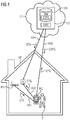
- FIG. 1 shows a first exemplary arrangement for assigning the location position to a device G, in particular as part of the commissioning of the device G within a building management system GMS.
- the first exemplary arrangement comprises: a position determining system IPS for determining the location position OPG of a mobile communication terminal MG located in the vicinity of the device G; wherein the mobile communication terminal MG, set up for transmitting the position OPG to the device G, and wherein the mobile communication terminal MG is arranged that the transmission of the position OPG from the mobile communication terminal MG to the device G only takes place when the device G before the transmission has been identified as an authorized recipient.
- the first exemplary arrangement comprises a building model BIM stored in a database DB in which respective desired location positions SOPG of devices G installed or to be installed are stored.
- the person P is e.g. a service technician assigned to install in the building GB a device G (e.g., sensor, actuator, controller, fire detector, thermostat, etc.).
- a device G e.g., sensor, actuator, controller, fire detector, thermostat, etc.
- the location position OPG of the mobile communication terminal MG (for example smartphone, tablet computer) of the person P located in the spatial vicinity of the device G is determined.
- the positioning system IPS is e.g. an indoor positioning system (WLAN, Bluetooth, IBeacon, etc.) or a satellite positioning system (e.g., GPS, Galileo).
- the mobile communication terminal MG of the user P is transmitted via a suitable communication link KV1, the location position OPG and displayed with advantage on the display of the mobile communication terminal MG.
- the communication link KV1 is e.g. a wireless connection (e.g., wireless, WLAN, Bluetooth, NFC (Near Field Communication)).
- the mobile communication terminal MG is set up for transmitting the location OPG to the device G via a suitable communication link KV2 (eg radio, WLAN, Bluetooth, NFC (Near Field Communication)).
- a suitable communication link KV2 eg radio, WLAN, Bluetooth, NFC (Near Field Communication)
- the mobile communication terminal MG transmits the location OPG to the device G only if the device G has been identified as an authorized recipient.
- the identification of the device G as an authorized recipient of the spatial position OPG can eg via a comparison of the device data with corresponding data to the device, which are stored in the building model BIM done.
- the mobile communication terminal MG for example, by a corresponding QR code scanner or barcode scanner a corresponding attached to the device label (eg QR code or barcode) read and check whether it is a legitimate device G is (correct type, right product line) , By accessing the corresponding building model (BIM model), the mobile communication terminal MG can be used to check whether the device G is an authorized recipient.
- the mobile communication terminal MG eg smartphone, tablet computer
- KV3 eg wireless radio connection or satellite-based connection
- the transmission of the spatial position OPG from the mobile communication terminal MG to the device G comprises a signature which is based on the location position OPG and an identification code (eg unique ID) of the device.
- control center LS comprises a building management system GMS, which has access to a database DB, in which the building model BIM of the building GB is stored.
- the LS control system comprises a powerful and suitably equipped server for the operation of the building management system GMS.
- the database DB may be e.g. to be an in-memory database or a relational database.
- the building model BIM is described in a suitable notation and stored in the database DB.
- the control system LS is implemented in a cloud infrastructure C.
- the identification is carried out as the authorized recipient by the device G.
- the identification of the device G as an authorized recipient can also be done by the mobile communication terminal MG or in a collaboration of device G, the mobile communication terminal MG and the control center LS.
- the transmission of the spatial position OPG from the mobile communication terminal MG to the device G can take place in a direct connection KV2 between the mobile communication terminal MG and the device G (for example actuator, sensor, controller), or indirectly via a third-party device.
- the third device may be e.g. to the control center LS, in particular a building management station or a BIM server act.
- the mobile communication terminal MG can transmit the location position OPG to the control center LS for entry into the building model BIM.
- the control center LS can compare the obtained location position OPG (i.e., the actual location position) with a desired location position SOPG stored in the building model BIM and, in the event of deviations, e.g. Send a message to a building operator or facility manager.
- the control center LS can transmit the location position OPG to the device G via a suitable communication link KV4 (for example wireless radio link).
- a comparison between the corresponding desired spatial position SOPG and the spatial position OPG takes place before the transmission.
- a planned target location position SOPG of the device G is queried from a building model BIM stored in a database DB by the mobile communication terminal MG, in particular after a request (on demand) of the mobile communication terminal MG; wherein a transmission of the spatial position OPG from the mobile communication terminal MG to the device G only takes place when the location determined by the positioning system IPS position OPG of located in the vicinity of the device G mobile communication terminal MG coincides with the planned target spatial position SOPG.
- the comparison of the desired location position SOPG with the position determined by the positioning system IPS position OPG ie the actual location position
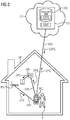
- FIG. 2 shows a second exemplary arrangement for the assignment of the spatial position OPG to a device G (eg, field device, actuator, sensor, controller), in particular in the context of the commissioning of the device G for a building management system GMS.
- the exemplary arrangement according to FIG. 2 comprises a position determining system IPS for determining the spatial position OPG of a mobile communication terminal MG located in the vicinity of the device G; wherein the mobile communication terminal MG, set up for transmitting the position OPG to the device G, and wherein the mobile communication terminal MG is arranged that the transmission of the position OPG from the mobile communication terminal MG to the device G only takes place when the device G before the transmission has been identified as an authorized recipient.
- the location position OPG of the mobile communication terminal MG (eg smartphone, tablet computer) of the person P located in the spatial vicinity of the device G is determined.
- the position determination system IPS is, for example, an indoor positioning system (WLAN, Bluetooth, IBeacon, etc.) or a satellite-supported position determination system (eg GPS, Galileo).
- the mobile communication terminal MG of the user P is the via a suitable communication link KV1 Position OPG transmitted and displayed with advantage on the display of the mobile communication terminal MG.
- the communication connection KV1 is, for example, a wireless connection (eg radio, WLAN, Bluetooth, NFC (Near Field Communication)).
- the exemplary arrangement according to FIG. 2 a stored in a database DB building model BIM are deposited in the respective target location positions SOPG of installed or to be installed devices G.
- the database DB is eg part of a building management system GMS or a control center LS.
- the identification of the device G as authorized recipient of the position of location OPG may e.g. via a comparison of the device data with corresponding data to the device G, which are stored in the building model BIM done.
- the mobile communication terminal MG may e.g. use a corresponding QR code scanner or barcode scanner to read a corresponding tag attached to the device (such as a QR code or barcode) and check if it is a legitimate device G (correct type, right product line). By accessing the corresponding building model (BIM model), the mobile communication terminal MG can be used to check whether the device G is an authorized recipient.
- the mobile communication terminal MG e.g., smartphone, tablet computer
- KV3 e.g., wireless radio link or satellite-based connection.
- the transmission of the position OPG from the mobile communication terminal MG to the device G can also be done via a third party DG (eg a tester).
- the third device DG is a device which is located in the immediate vicinity spatial proximity of the device G is located, in particular at a distance of less than 1m from the device G.
- This indirect transmission of the position OPG from the mobile communication terminal MG to the device G is particularly useful in those cases where no direct or no sufficient connection between the Device G and the mobile communication terminal MG (eg smartphone) exists or can be produced.
- the location position OPG is transferred from the mobile communication terminal MG in a first step to the third party DG DG (eg a tester or a suitable additional field device (eg fire detector, thermostat)) and from the third device DG to the device G, via suitable communication links KV5 , KV6.
- the communication connections KV5, KV6 are advantageously wireless connections (eg radio connections).
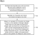
- FIG. 3 shows an exemplary flowchart for a method for assigning the spatial position to a device (eg field device for building automation, actuator, sensor, controller), especially during the commissioning of the device.
- the method comprises the following steps: (VS1) Determining the spatial position of a mobile communication terminal (eg smartphone, tablet computer) located in the vicinity of the device by a position determination system (eg satellite-based positioning system (eg GPS, Galileo) and / or indoor). Positioning system (eg WLAN, BLE, IBeacons); and (VS2) transmitting the location position from the mobile communication terminal to the device.
- a position determination system eg satellite-based positioning system (eg GPS, Galileo) and / or indoor).
- Positioning system eg WLAN, BLE, IBeacons
- VS2 transmitting the location position from the mobile communication terminal to the device.
- the method further comprises the step: (VS3) querying a planned target spatial position of the device from a building model stored in a database (eg Building information model, BIM) by the mobile communication terminal; wherein the transmission of the spatial position of the mobile communication terminal to the device only takes place when determined by the positioning system spatial position of located in the vicinity of the device mobile communication terminal with the planned target location position matches.
- a database eg Building information model, BIM
- a corresponding method can be implemented by hardware and software components already present in a building or within the framework of a building automation. It is also easily possible to equip or upgrade a building or a building automation by commercially available components (eg smartphone, server, memory, communication mechanisms (eg WLAN, Internet) in order to implement the method according to the invention.)
- the method is implemented by a cloud infrastructure
- a building control center can be implemented in a computer cloud with appropriate hardware, software and communication mechanisms (Internet, WLAN, server, database for BIM, etc.) for communication into the field or into the building a building management system that maintains or monitors the entries and access to the building information model.
- the transmission of the spatial position from the mobile communication terminal to the device takes place only if the device has been identified as an authorized recipient. This can be done, for example, by comparing the data on the physical device (eg serial number, type, etc.) with the corresponding data stored in the BIM model.
- the BIM model may be based on Industry Foundation Classes (IFC) or some other equivalent notation.
- Identification as an authorized recipient may be by the device or may be performed by the mobile communication terminal, e.g. through appropriate checks and comparisons with corresponding entries in the BIM model.
- the transmission of the location from the mobile communication terminal to the device can be done indirectly via a third party device (e.g., server in the cloud or via a field tester).
- the third-party device can be a control center, in particular a building management station or a BIM server.
- the third device may also be a device which is located in the immediate vicinity of the device, in particular at a distance of less than 1 m from the device.
- transmitting the location position from the mobile communication terminal to the device includes a signature based on the location position and an identification code (e.g., unique ID) of the device.
- an identification code e.g., unique ID
- One aspect of the present invention is the use of "position awareness" of a mobile communication terminal (eg smartphone of a service technician).
- a mobile communication terminal eg smartphone of a service technician
- the recognized or known position of the communication terminal to a device or product eg building technology sensor
- This location may be optional without the need for a communication channel between product / device and "system” (eg, building management software, building management system) continue to be transmitted by the communication terminal to the "system”.
- a communication terminal eg smartphone, recognizes its position.
- This position detection takes place eg via GPS, indoor navigation infrastructure, camera-based environment recognition (comparison camera image with image database of the environment) or point cloud-matching, with advantage of combination of various information ("sensor fusion").
- a coordinate advantageously including Z-axis, (eg via barometer, known construction plans (ceiling height), geomagnetic field, radio signal evaluation, etc.), determined or fixed.
- This can be, for example, a value based on standards (eg ID value, eg WGS84 or UTM coordinate (World Geodetic System 1984Universal Transverse Mercator), or, for example, a location-specific ID (identification) in which a building corner is defined as the zero point.
- this position coordinate is transmitted to the device / product (e.g., a sensor).
- the device / product which is to receive the position indicates its readiness to receive (acoustic or optical signal, or as status message via radio or online connection within a software system (for example App)).
- a software system for example App
- the devices / products are authorized; either directly (e.g., programming button, or via hardware or software "dongle” (online service), e.g., by optical alignment (e.g., by QR or Bar code reading)).
- directly e.g., programming button, or via hardware or software "dongle” (online service), e.g., by optical alignment (e.g., by QR or Bar code reading)).
- optical alignment e.g., by QR or Bar code reading
- Method and arrangement for assigning the spatial position to a device in particular in the context of commissioning of the device (eg field device, actuator, sensor), which is determined by a position determination system, the spatial position of a located in spatial proximity of the device mobile communication terminal; wherein the mobile communication terminal (eg smartphone) is set up to transmit the location position to the device, and wherein the mobile communication terminal is further configured that the transmission of the location from the mobile communication terminal to the device only takes place if the device before the transmission as an authorized recipient has been identified.
- the device eg field device, actuator, sensor
Landscapes
- Engineering & Computer Science (AREA)
- Computer Networks & Wireless Communication (AREA)
- Signal Processing (AREA)
- Physics & Mathematics (AREA)
- General Physics & Mathematics (AREA)
- Radar, Positioning & Navigation (AREA)
- Remote Sensing (AREA)
- Telephonic Communication Services (AREA)
- Mobile Radio Communication Systems (AREA)
Abstract
Description
- Die Erfindung betrifft ein Verfahren und eine Anordnung zur Zuordnung der Ortsposition an ein Gerät, insbesondere im Rahmen der Inbetriebsetzung des Gerätes.
- Die Zahl der in Gebäuden verbauten Technik bzw. Geräte, z.B. Sensoren oder Aktoren jeglicher Art, nimmt zu. Das Problem dabei ist, dass die verbaute Technik meistens keine "position awareness" besitzt, d.h. die verbaute Technik bzw. die verbauten Geräte kann bzw. können den Ort an welchem sie sich in einem Gebäude befinden nicht an ein übergeordnetes System (z.B. Gebäudemanagementsystem, Leitsystem, Leitwarte), z.B. zur Inventarisierung, rückmelden.
- Dies verursacht hohe Kosten und Aufwände, da diese Rückmeldung meist händisch erfolgen muss. Dabei wird von einem Servicetechniker die Position der Geräte, meist ungenau, manuell erfasst. Ist dieser Schritt erfolgt, mit dem Risiko dass dabei versehentlich falsche Daten erfasst wurden, weiss das übergeordnete System über den Verbauungsort der Geräte. Sollte es jedoch keinen Kommunikationskanal vom übergeordneten System an das verbaute Gerät geben, kennt dieses (z.B. Sensor, Aktor, Controller) jedoch die eigenen Positionsdaten noch immer nicht. Mangels dieser Information wird das Gerät u.U. weniger effizient arbeiten. Auch sind Wartung oder Fehlerbehebung am Gerät nicht effizient durchführbar, da der benötigte manuelle Abgleich zwischen einem Plan (Soll-Positionsdaten) und dem Gerät im Feld (Ist-Positionsdaten) immer fehlerbehaftet ist.
- Es ist daher die Aufgabe der vorliegenden Erfindung ein Verfahren bzw. eine Anordnung zur Zuordnung der Ortsposition an verbaute oder an zu verbauende Geräte bereitzustellen, wobei sichergestellt ist, dass jeweilige Soll-Positionsdaten und Ist-Positionsdaten der jeweiligen Geräte übereinstimmen.
- Die Aufgabe wird gelöst durch ein Verfahren zur Zuordnung der Ortsposition an ein Gerät, insbesondere im Rahmen der Inbetriebsetzung des Gerätes, das Verfahren umfasst die folgenden Schritte:
- Bestimmen der Ortsposition eines sich in räumlicher Nähe des Gerätes befindlichen mobilen Kommunikationsendgerätes durch ein Positionsbestimmungssystem;
- Übermitteln der Ortsposition vom mobilen Kommunikationsendgerät (z.B. Smartphone, Tablet-Computer) an das Gerät. Heutzutage wird insbesondere in intelligenten Gebäuden (Smart Homes) verstärkt auf sog. "distributed wireless conntected devices" zurückgegriffen, d.h. auf nicht direkt miteinander verkabelte Geräte. So sind z.B. ein Lichtschalter und die dazugehörige Leuchte nur logisch miteinander verknüpft. Für die Programmierung der Beziehung Lichtschalter - Leuchte (Zuordnung; logische Verknüpfung) nach der Montage ist es wichtig dass diese Geräte sich auch dort befinden wo sie geplant waren. Speziell bei durch Funk angesteuerten Geräten (Funk-Devices) hat eine Ortsabweichung einen mehr oder minder grossen Einfluss auf die Funktionsqualität und Kommunikationsfähigkeit dieser Geräte. Wenn ein Gerät seine Ortsposition kennt, kann es leicht mit anderen zugeordneten Geräten kommunizieren und kooperieren. Mit Vorteil handelt es sich beim Positionsbestimmungssystem um ein Indoor-Positionsbestimmungssystem (z.B. WLAN, WLAN-ID des WLAN-Access Point, Bluetooth, IBeacons), welches sowieso schon im Gebäude installiert ist. Mobile Kommunikationsendgeräte mit entsprechenden Kommunikationsmechanismen sind heutzutage weitverbreitet bzw. lassen sich durch entsprechende Apps leicht nachrüsten.
- Wenn ein in einem Gebäude verbautes oder zu verbauendes Gerät (z.B. Feldgerät, Controller) seine Ortsinformation kennt, d.h. den Ort, wo es im Gebäude sich befindet, kann es sich z.B. mit anderen Geräten im Gebäude verbinden (z.B. in ein mesh-Netzwerk integrieren). Weiterhin kann das Gerät in einem Fehlerfall oder bei einer benötigten Wartung die Ortsinformation einem Servicetechniker melden. Die erleichtert Fehlersuche und Wartung. Mit Vorteil wird einem Gerät seine Ortsinformation (bzw. sein Verbauungsort) während der Inbetriebnahme zugewiesen, bzw. übermittelt.
- Eine erste vorteilhafte Ausgestaltung der Erfindung liegt darin, dass das Übermitteln der Ortsposition vom mobilen Kommunikationsendgerät an das Gerät nur erfolgt, wenn das Gerät als berechtigter Empfänger identifiziert wurde. Dies kann z.B. durch einen optischen Abgleich zwischen dem mobilen Kommunikationsendgerät und dem zu "impfenden" Gerät (d.h. dem Gerät, dem die Ortsposition mitgeteilt werden soll) erfolgen. Das mobile Kommunikationsendgerät kann z.B. durch einen entsprechenden QR-Code Scanner oder Barcode-Scanner einen entsprechende am Gerät angebrachte Markierung (z.B. QR Code oder Barcode) einlesen und überprüfen, ob es sich um ein berechtigtes Gerät handelt (richtiger Typ, richtige Produktlinie). Durch Zugriff auf das entsprechende Gebäudemodell (BIM-Modell) kann mit dem mobilen Kommunikationsendgerät überprüft werden, ob es sich beim Gerät um einen berechtigten Empfänger handelt.
- Ein Gerät kann sich als berechtigt entweder direkt (z.B. Programmierknopf) oder via Hard- oder Software-"Mittelsmann" (z.B. dongle oder online-Service) identifizieren.
- Eine weitere vorteilhafte Ausgestaltung der Erfindung liegt darin, dass die Identifikation als berechtigter Empfänger durch das Gerät erfolgt. Das entsprechende Gerät bzw. das entsprechende Produkt welches die Position übermittelt bekommen soll, kann seine Empfangsbereitschaft z.B. durch ein akustisches oder optisches Signal (z.B. blinkende LED am Gerät/Produkt). Die Empfangsbereitschaft kann auch durch eine entsprechende Statusmeldung dem mobilen Kommunikationsendgerät mitgeteilt werden. Z.B. via Funk- oder online-Verbindung innerhalb einer entsprechenden Software bzw. App, mit Vorteil auch mit Empfangsquittierung bzw. OK-Meldung.
- Eine weitere vorteilhafte Ausgestaltung der Erfindung liegt darin, dass die Identifikation des Gerätes als berechtigter Empfänger durch das mobile Kommunikationsendgerät erfolgt. Das mobile Kommunikationsendgerät kann z.B. durch eine NFC-Verbindung (z.B. Bluetooth) das entsprechende Gerät auffordern sich als berechtigt zu identifizieren. Das Gerät kann z.B. ein entsprechendes akustisches oder optisches Signal ausgeben, oder eine Quittungsmeldung dem mobilen Kommunikationsendgerät antworten. Durch Zugriff auf das entsprechende Gebäudemodell (BIM-Modell) kann mit dem mobilen Kommunikationsendgerät überprüft werden, ob es sich beim Gerät um einen berechtigten Empfänger handelt.
- Eine weitere vorteilhafte Ausgestaltung der Erfindung liegt darin, dass die Übermittlung der Ortsposition vom mobilen Kommunikationsendgerät an das Gerät über ein Drittgerät erfolgt. So können die Positionsdaten (Ortsposition) des mobilen Kommunikationsendgeräts von diesem an ein Prüfgerät oder Installationswerkzeug übertragen werden, welches wiederum die empfangene Position an das eigentliche Gerät bzw. Produkt überträgt. Dies ist besonders bei Brownfield-Projekten von Vorteil.
- Eine weitere vorteilhafte Ausgestaltung der Erfindung liegt darin, dass es sich beim Drittgerät um eine Leitstelle, insbesondere eine Gebäudemanagementstation oder ein BIM-Server, handelt. Mit Vorteil überträgt das mobile Kommunikationsendgerät eine einem Gerät zugeordnete bzw. übermittelte Ortsposition auch an eine übergeordnete Stelle, wie z.B. Leitstelle, Gebäudemanagementsystem zur Ablage der Ortsinformation in einem Gebäudeinformationsmodell (BIM-Modell). Von der Leitstelle (z.B. Gebäudemanagementstation, BIM-Server, Gebäudemanagementsystem) kann die Ortsposition an das entsprechende Gerät weitergeleitet werden. Damit wird u.a. sichergestellt, dass die dem Gerät zugewiesene und übermittelte Ortsposition mit der entsprechenden im Gebäudeinformationsmodell (BIM-Modell) hinterlegten Ortsposition übereinstimmt.
- Eine weitere vorteilhafte Ausgestaltung der Erfindung liegt darin, dass es sich beim Drittgerät um ein Gerät handelt, welches sich in unmittelbarer räumlicher Nähe des Gerätes befindet, insbesondere in einer Entfernung von weniger als 1m vom Gerät. Dies ist insbesondere dann von Vorteil, wenn das Gerät keine eigene Verbindung zum mobilen Kommunikationsendgerät aufbauen kann, wohl aber das in der Nähe des Gerätes befindliche Drittgerät. Mit Vorteil sind das Gerät und das Drittgerät durch ein Kommunikationsnetzwerk (z.B. Installationsbus oder mesh-Netzwerk) verbunden, worüber diese kommunizieren können. Bei einer geringen Entfernung, insbesondere bei einer Entfernung von weniger als 1m zwischen Gerät und Drittgerät, kann mit Vorteil eine Nahfeld-Kommunikation (NFC, Near Field Communication, z.B. RFID, Bluetooth) verwendet werden.
- Eine weitere vorteilhafte Ausgestaltung der Erfindung liegt darin, dass das Übermitteln der Ortsposition vom mobilen Kommunikationsendgerät an das Gerät eine Signatur umfasst, die auf der Ortsposition und einem Identifikationscode (z.B. eindeutige ID) des Gerätes basiert. Dadurch wird ein sicheres Übermitteln der Ortsposition vom mobilen Kommunikationsendgerät an das Gerät gewährleistet. Eine digitale Signatur kann z.B. durch ein digitales Signaturverfahren (z.B. durch ein asymmetrisches Kryptosystem oder ein Public-Key-Kryptosystem) erstellt werden.
- Eine weitere vorteilhafte Ausgestaltung der Erfindung liegt darin, dass das Verfahren weiterhin umfasst:
- Abfragen einer geplanten Soll-Ortsposition des Gerätes aus einem in einer Datenbank hinterlegten Gebäudemodell (BIM, Gebäudeinformationsmodell) durch das mobile Kommunikationsendgerät;
- wobei das Übermitteln der Ortsposition vom mobilen Kommunikationsendgerät an das Gerät nur erfolgt, wenn die vom Positionsbestimmungssystem ermittelte Ortsposition des sich in räumlicher Nähe des Gerätes befindlichen mobilen Kommunikationsendgerätes mit der geplanten Soll-Ortsposition übereinstimmt. Dadurch wird sichergestellt, dass die Soll-Ortsposition des Gerätes wie sie im Gebäudemodell (BIM, Gebäudeinformationsmodell) hinterlegt ist, mit der physikalischen Ortsposition des Gerätes im Feld (d.h. im Gebäude) übereinstimmt.
- Die Soll-Zielposition des "zu impfenden" Gerätes (z.B. Rauchmelder) ist in einer Datenbank (z.B. BIM-Modell) hinterlegt. Diese Soll-Zielposition wird dem Kommunikationsendgerät übermittelt. Dies kann z.B. eine technische Zeichnung (CAD) sein. Stimmt die Soll-Zielposition mit der Ist-Zielposition überein oder weisen nur eine definierte Abweichung (z.B. eine Abweichung von höchstens 3 m, insbesondere höchstens 1 m) auf, wird diese hinterlegte Soll-Zielposition dem "zu impfenden" Gerät übermittelt.
- Eine weitere vorteilhafte Ausgestaltung der Erfindung liegt in einer Anordnung eingerichtet zur Durchführung des erfindungsgemässen Verfahrens. Eine entsprechende Anordnung kann durch sowieso schon vorhandene Hardware- und Softwarekomponenten realisiert werden bzw. durch handelsübliche Komponenten (z.B. Smartphone, Server, Speicher, Kommunikationsmechanismen (z.B. WLAN, Internet) ausgestattet werden, um das erfindungsgemässe Verfahren zu realisieren.
- Die Aufgabe wird weiterhin gelöst durch eine Anordnung zur Zuordnung der Ortsposition an ein Gerät, insbesondere im Rahmen der Inbetriebsetzung des Gerätes, wobei die Anordnung umfasst:
- ein Positionsbestimmungssystem zum Bestimmen der Ortsposition eines sich in räumlicher Nähe des Gerätes befindlichen mobilen Kommunikationsendgerätes (z.B. Smartphone);
- das mobile Kommunikationsendgerät, eingerichtet zum Übermitteln der Ortsposition an das Gerät,
- Eine weitere vorteilhafte Ausgestaltung der Erfindung liegt darin, dass die Anordnung ein in einer Datenbank hinterlegtes Gebäudemodell (BIM, Gebäudeinformationsmodell) umfasst, in dem jeweilige Soll-Ortspositionen von verbauten oder zu verbauenden Geräten hinterlegt sind. Das mobile Kommunikationsendgerät kann durch entsprechende Kommunikationsverbindungen (z.B. Funk, WLAN, Internet) auf das Gebäudemodell zugreifen und z.B. Überprüfungen zwischen den im Gebäudemodell hinterlegten Solldaten und den im Feld vorliegenden Ist-Daten vornehmen.
- Die Erfindung sowie vorteilhafte Ausführungen der vorliegenden Erfindung werden am Beispiel der nachfolgenden Figuren erläutert. Dabei zeigen:
- FIG 1
- eine erste beispielhafte Anordnung zur Zuordnung der Ortsposition an ein Gerät, insbesondere im Rahmen der Inbetriebsetzung des Gerätes,
- FIG 2
- eine zweite beispielhafte Anordnung zur Zuordnung der Ortsposition an ein Gerät, insbesondere im Rahmen der Inbetriebsetzung des Gerätes, und
- FIG 3
- ein beispielhaftes Flussdiagramm für ein Verfahren zur Zuordnung der Ortsposition an ein Gerät, insbesondere im Rahmen der Inbetriebsetzung des Gerätes.
-
Figur 1 zeigt eine erste beispielhafte Anordnung zur Zuordnung der Ortsposition an ein Gerät G, insbesondere im Rahmen der Inbetriebsetzung des Gerätes G innerhalb eines Gebäudemanagementsystems GMS. Die erste beispielhafte Anordnung umfasst:
ein Positionsbestimmungssystem IPS zum Bestimmen der Ortsposition OPG eines sich in räumlicher Nähe des Gerätes G befindlichen mobilen Kommunikationsendgerätes MG; wobei das mobile Kommunikationsendgerät MG, eingerichtet zum Übermitteln der Ortsposition OPG an das Gerät G, und wobei das mobile Kommunikationsendgerät MG eingerichtet ist, dass das Übermitteln der Ortsposition OPG vom mobilen Kommunikationsendgerät MG an das Gerät G nur erfolgt, wenn das Gerät G vor der Übermittlung als berechtigter Empfänger identifiziert worden ist. - Mit Vorteil umfasst die erste beispielhafte Anordnung ein in einer Datenbank DB hinterlegtes Gebäudemodell BIM in dem jeweilige Soll-Ortspositionen SOPG von verbauten oder zu verbauenden Geräten G hinterlegt sind.
- Bei der Person P handelt es sich z.B. um einen Servicetechniker, der beauftragt ist im Gebäude GB ein Gerät G, (z.B. Sensor, Aktor, Controller, Brandmelder, Thermostat, etc.) zu installieren.
- Mit dem Positionsbestimmungssystem IPS wird die Ortsposition OPG des sich in räumlicher Nähe des Gerätes G befindlichen mobilen Kommunikationsendgerätes MG (z.B. Smartphone, Tablet-Computer) der Person P ermittelt. Beim Positionsbestimmungssystem IPS handelt es sich z.B. um ein Indoor-Positionsbestimmungssystem (WLAN, Bluetooth, IBeacon, etc.) oder um ein satellitengestütztes Positionsbestimmungssystem (z.B. GPS, Galileo). Dem mobilen Kommunikationsendgerät MG des Benutzers P wird über eine geeignete Kommunikationsverbindung KV1 die Ortsposition OPG übermittelt und mit Vorteil auf dem Display des mobilen Kommunikationsendgerätes MG angezeigt. Bei der Kommunikationsverbindung KV1 handelt es sich z.B. um eine Drahtlosverbindung (z.B. Funk, WLAN, Bluetooth, NFC (Near Field Communication)).
- Das mobile Kommunikationsendgerät MG ist eingerichtet zum Übermitteln der Ortsposition OPG an das Gerät G über eine geeignete Kommunikationsverbindung KV2 (z.B. Funk, WLAN, Bluetooth, NFC (Near Field Communication)). Mit Vorteil übermittelt das mobile Kommunikationsendgerät MG die Ortsposition OPG an das Gerät G nur, wenn das Gerät G als berechtigter Empfänger identifiziert worden ist. Die Identifizierung des Gerätes G als berechtigter Empfänger der Ortsposition OPG kann z.B. über einen Abgleich der Gerätedaten mit entsprechenden Daten zum Gerät, die im Gebäudemodell BIM hinterlegt sind erfolgen. Das mobile Kommunikationsendgerät MG kann z.B. durch einen entsprechenden QR-Code Scanner oder Barcode-Scanner einen entsprechende am Gerät angebrachte Markierung (z.B. QR Code oder Barcode) einlesen und überprüfen, ob es sich um ein berechtigtes Gerät G handelt (richtiger Typ, richtige Produktlinie). Durch Zugriff auf das entsprechende Gebäudemodell (BIM-Modell) kann mit dem mobilen Kommunikationsendgerät MG überprüft werden, ob es sich beim Gerät G um einen berechtigten Empfänger handelt. Das mobile Kommunikationsendgerät MG (z.B. Smartphone, Tablet-Computer) ist dabei über eine geeignete Kommunikationsverbindung KV3 (z.B. drahtlose Funkverbindung oder satellitengestützte Verbindung) mit der Leitstelle LS verbunden. Mit Vorteil umfasst das Übermitteln der Ortsposition OPG vom mobilen Kommunikationsendgerät MG an das Gerät G eine Signatur, die auf der Ortsposition OPG und einem Identifikationscode (z.B. eindeutige ID) des Gerätes basiert.
- Mit Vorteil umfasst die Leitstelle LS ein Gebäudemanagementsystem GMS, welches Zugriff auf eine Datenbank DB hat, worin das Gebäudemodell BIM des Gebäudes GB hinterlegt ist. Das Leitsystem LS umfasst einen leistungsfähigen und entsprechend eingerichteten Server für den Betrieb des Gebäudemanagementsystems GMS. Bei der Datenbank DB kann es sich z.B. um eine In-Memory Datenbank oder eine relationale Datenbank handeln. Das Gebäudemodell BIM ist in einer geeigneten Notation beschrieben und in der Datenbank DB hinterlegt. Mit Vorteil ist das Leitsystem LS in einer Cloud-Infrastruktur C realisiert.
- Mit Vorteil erfolgt die Identifikation als berechtigter Empfänger durch das Gerät G.
- Die Identifikation des Gerätes G als berechtigter Empfänger kann auch durch das mobile Kommunikationsendgerät MG erfolgen oder in einer Kollaboration von Gerät G, dem mobilen Kommunikationsendgerät MG und der Leitstelle LS.
- Die Übermittlung der Ortsposition OPG vom mobilen Kommunikationsendgerät MG an das Gerät G kann in einer direkten Verbindung KV2 zwischen dem mobilen Kommunikationsendgerät MG und dem Gerät G (z.B. Aktor, Sensor, Controller) erfolgen, oder auch indirekt über ein Drittgerät. Beim Drittgerät kann es sich z.B. um die Leitstelle LS, insbesondere eine Gebäudemanagementstation oder ein BIM-Server, handeln. Das mobile Kommunikationsendgerät MG kann die Ortsposition OPG an die Leitstelle LS übertragen, zum Eintragen in das Gebäudemodell BIM. Die Leitstelle LS kann die erhaltene Ortsposition OPG (d.h. die Ist-Ortsposition) mit einer im Gebäudemodell BIM hinterlegten Soll-Ortsposition SOPG abgleichen und bei Abweichungen z.B. eine entsprechende Meldung an einen Gebäudebetreiber oder Facility-Manager absetzen. Die Leitstelle LS kann über eine geeignete Kommunikationsverbindung KV4 (z.B. drahtlose Funkverbindung) die Ortsposition OPG an das Gerät G übermitteln. Mit Vorteil findet vor der Übermittlung ein Abgleich zwischen der entsprechenden Soll-Ortsposition SOPG und der Ortsposition OPG statt.
- Mit Vorteil erfolgt ein Abfragen einer geplanten Soll-Ortsposition SOPG des Gerätes G aus einem in einer Datenbank DB hinterlegten Gebäudemodell BIM durch das mobile Kommunikationsendgerät MG, insbesondere nach einer Aufforderung (on demand) des mobile Kommunikationsendgerätes MG; wobei ein Übermitteln der Ortsposition OPG vom mobilen Kommunikationsendgerät MG an das Gerät G nur erfolgt, wenn die vom Positionsbestimmungssystem IPS ermittelte Ortsposition OPG des sich in räumlicher Nähe des Gerätes G befindlichen mobilen Kommunikationsendgerätes MG mit der geplanten Soll-Ortsposition SOPG übereinstimmt. Der Abgleich der Soll-Ortsposition SOPG mit der vom Positionsbestimmungssystem IPS ermittelten Ortsposition OPG (d.h. der Ist-Ortsposition) kann durch ein entsprechend eingerichtetes mobiles Kommunikationsendgerät MG oder durch entsprechende Mechanismen der Leitstelle LS bzw. des Gebäudemanagementsystems GMS erfolgen.
-
Figur 2 zeigt eine zweite beispielhafte Anordnung zur Zuordnung der Ortsposition OPG an ein Gerät G (z.B. Feldgerät, Aktor, Sensor, Controller), insbesondere im Rahmen der Inbetriebsetzung des Gerätes G für ein Gebäudemanagementsystem GMS. Die beispielhafte Anordnung gemässFigur 2 umfasst ein Positionsbestimmungssystem IPS zum Bestimmen der Ortsposition OPG eines sich in räumlicher Nähe des Gerätes G befindlichen mobilen Kommunikationsendgerätes MG; wobei das mobile Kommunikationsendgerät MG, eingerichtet zum Übermitteln der Ortsposition OPG an das Gerät G, und wobei das mobile Kommunikationsendgerät MG eingerichtet ist, dass das Übermitteln der Ortsposition OPG vom mobilen Kommunikationsendgerät MG an das Gerät G nur erfolgt, wenn das Gerät G vor der Übermittlung als berechtigter Empfänger identifiziert worden ist. - Mit dem Positionsbestimmungssystem IPS wird die Ortsposition OPG des sich in räumlicher Nähe des Gerätes G befindlichen mobilen Kommunikationsendgerätes MG (z.B. Smartphone, Tablet-Computer) der Person P ermittelt. Beim Positionsbestimmungssystem IPS handelt es sich z.B. um ein Indoor-Positionsbestimmungssystem (WLAN, Bluetooth, IBeacon, etc.) oder um ein satellitengestütztes Positionsbestimmungssystem (z.B. GPS, Galileo). Dem mobilen Kommunikationsendgerät MG des Benutzers P wird über eine geeignete Kommunikationsverbindung KV1 die Ortsposition OPG übermittelt und mit Vorteil auf dem Display des mobilen Kommunikationsendgerätes MG angezeigt. Bei der Kommunikationsverbindung KV1 handelt es sich z.B. um eine Drahtlosverbindung (z.B. Funk, WLAN, Bluetooth, NFC (Near Field Communication)).
- Mit Vorteil umfasst die beispielhafte Anordnung gemäss
Figur 2 ein in einer Datenbank DB hinterlegtes Gebäudemodell BIM in dem jeweilige Soll-Ortspositionen SOPG von verbauten oder zu verbauenden Geräten G hinterlegt sind. Die Datenbank DB ist z.B. Bestandteil eines Gebäudemanagementsystems GMS bzw. einer Leitstelle LS. - Die Identifizierung des Gerätes G als berechtigter Empfänger der Ortsposition OPG kann z.B. über einen Abgleich der Gerätedaten mit entsprechenden Daten zum Gerät G, die im Gebäudemodell BIM hinterlegt sind erfolgen. Das mobile Kommunikationsendgerät MG kann z.B. durch einen entsprechenden QR-Code Scanner oder Barcode-Scanner einen entsprechende am Gerät angebrachte Markierung (z.B. QR Code oder Barcode) einlesen und überprüfen, ob es sich um ein berechtigtes Gerät G handelt (richtiger Typ, richtige Produktlinie). Durch Zugriff auf das entsprechende Gebäudemodell (BIM-Modell) kann mit dem mobilen Kommunikationsendgerät MG überprüft werden, ob es sich beim Gerät G um einen berechtigten Empfänger handelt. Das mobile Kommunikationsendgerät MG (z.B. Smartphone, Tablet-Computer) ist dabei über eine geeignete Kommunikationsverbindung KV3 (z.B. drahtlose Funkverbindung oder satellitengestützte Verbindung) mit der Leitstelle LS verbunden.
- Die Übermittlung der Ortsposition OPG vom mobilen Kommunikationsendgerät MG an das Gerät G kann auch über ein Drittgerät DG (z.B. ein Prüfgerät) erfolgen. Mit Vorteil handelt es sich beim Drittgerät DG um ein Gerät, welches sich in unmittelbarer räumlicher Nähe des Gerätes G befindet, insbesondere in einer Entfernung von weniger als 1m vom Gerät G. Diese indirekte Übermittlung der Ortsposition OPG vom mobilen Kommunikationsendgerät MG an das Gerät G ist insbesondere in solchen Fällen sinnvoll, bei denen keine direkte oder keine ausreichende Verbindung zwischen dem Gerät G und dem mobilen Kommunikationsendgerät MG (z.B. Smartphone) besteht oder herstellbar ist. In solchen Fällen wird die Ortsposition OPG vom mobilen Kommunikationsendgerät MG in einem ersten Schritt an das Drittgerät DG (z.B. ein Prüfgerät oder ein geeignetes weiteres Feldgerät (z.B. Brandmelder, Thermostat)) und vom Drittgerät DG weiter an das Gerät G übertragen, über geeignete Kommunikationsverbindungen KV5, KV6. Bei den Kommunikationsverbindungen KV5, KV6 handelt es sich mit Vorteil um drahtlose Verbindungen (z.B. Funkverbindungen).
-
Figur 3 zeigt ein beispielhaftes Flussdiagramm für ein Verfahren zur Zuordnung der Ortsposition an ein Gerät (z.B. Feldgerät für die Gebäudeautomatisierung; Aktor, Sensor, Controller), insbesondere im Rahmen der Inbetriebsetzung des Gerätes. Das Verfahren umfasst die folgenden Schritte: (VS1) Bestimmen der Ortsposition eines sich in räumlicher Nähe des Gerätes befindlichen mobilen Kommunikationsendgerätes (z.B. Smartphone, Tablet-Computer) durch ein Positionsbestimmungssystem (z.B. Satelliten gestütztes Positionsbestimmungssystem (z.B. GPS, Galileo) und/oder Indoor- Positionsbestimmungssystem (z.B. WLAN, BLE, IBeacons); und
(VS2) Übermitteln der Ortsposition vom mobilen Kommunikationsendgerät an das Gerät. - Optional umfasst das Verfahren weiterhin den Schritt: (VS3) Abfragen einer geplanten Soll-Ortsposition des Gerätes aus einem in einer Datenbank hinterlegten Gebäudemodell (z.B. Gebäudeinformationsmodell, BIM) durch das mobile Kommunikationsendgerät; wobei das Übermitteln der Ortsposition vom mobilen Kommunikationsendgerät an das Gerät nur erfolgt, wenn die vom Positionsbestimmungssystem ermittelte Ortsposition des sich in räumlicher Nähe des Gerätes befindlichen mobilen Kommunikationsendgerätes mit der geplanten Soll-Ortsposition übereinstimmt.
- Ein entsprechendes Verfahren kann durch sowieso schon in einem Gebäude bzw. im Rahmen einer Gebäudeautomatisierung vorhandene Hardware- und Softwarekomponenten realisiert werden. Auch ist es leicht möglich ein Gebäude oder eine Gebäudeautomatisierung durch handelsübliche Komponenten (z.B. Smartphone, Server, Speicher, Kommunikationsmechanismen (z.B. WLAN, Internet) auszustatten oder aufzurüsten, um das erfindungsgemässe Verfahren zu realisieren. Mit Vorteil wird das Verfahren durch eine Cloud-Infrastruktur realisiert. So kann z.B. eine Gebäudeleitstelle in einer Rechner-Cloud realisiert werden mit entsprechender Hardware, Software und Kommunikationsmechanismen (Internet, WLAN, Server, Datenbank für BIM, etc.) für eine Kommunikation ins Feld bzw. in das Gebäude. Die Gebäudeleitstelle umfasst mit Vorteil ein Gebäudemanagementsystem, welches die Einträge und den Zugriff auf das Gebäudeinformationsmodell pflegt bzw. überwacht.
- Mit Vorteil erfolgt das Übermitteln der Ortsposition vom mobilen Kommunikationsendgerät an das Gerät nur, wenn das Gerät als berechtigter Empfänger identifiziert wurde. Dies kann z.B. durch Abgleich der Daten am physikalischen Gerät (z.B. Seriennummer, Typ, etc.) mit den entsprechenden im BIM-Modell hinterlegten Daten erfolgen. Das BIM-Modell kann z.B. auf Industry Foundation Classes (IFC) basieren oder einer anderen entsprechenden Notation.
- Die Identifikation als berechtigter Empfänger kann durch das Gerät erfolgen oder durch das mobile Kommunikationsendgerät, z.B. durch entsprechende Überprüfungen und Abgleiche mit entsprechenden Einträgen im BIM-Modell.
- Die Übermittlung der Ortsposition vom mobilen Kommunikationsendgerät an das Gerät kann indirekt über ein Drittgerät (z.B. Server in der Cloud oder über ein Prüfgerät im Feld) erfolgen. Es kann sich beim Drittgerät um eine Leitstelle, insbesondere eine Gebäudemanagementstation oder einen BIM-Server handeln. Es kann sich beim Drittgerät auch um ein Gerät handeln, welches sich in unmittelbarer räumlicher Nähe des Gerätes befindet, insbesondere in einer Entfernung von weniger als 1m vom Gerät.
- Mit Vorteil umfasst das Übermitteln der Ortsposition vom mobilen Kommunikationsendgerät an das Gerät eine Signatur, die auf der Ortsposition und einem Identifikationscode (z.B. eindeutige ID) des Gerätes basiert. Dies erhöht die Sicherheit der Übermittlung, insbesondere wird ein Man-in-the-middle-Angriff (MITM-Angriff) erschwert bzw. verhindert.
- Ein Aspekt der vorliegenden Erfindung ist die Nutzung der "position awareness" eines mobilen Kommunikationsendgerätes (z.B. Smartphone eines Servicetechnikers). Durch Nutzung der "position awareness" eines mobilen Kommunikationsendgerätes wird die erkannte bzw. bekannte Position des Kommunikationsendgerätes an ein Gerät oder Produkt (z.B. Gebäudetechnik-Sensor) weitergegeben bzw. programmiert. Diese Ortsposition (dann Geräte/Produkt-Position) kann, ohne dass ein Kommunikationskanals zwischen Produkt/Gerät und "System" (z.B. Gebäudemanagementsoftware, Gebäudemanagementsystem) bestehen muss, optional weiterhin durch das Kommunikationsendgerät an das "System" übermittelt werden.
Ein Kommunikationsendgerät, z.B. Smartphone, erkennt seine Position. Diese Positionserkennung erfolgt z.B. via GPS, Indoor Navigationsinfrastruktur, kamerabasierter Umfelderkennung (Abgleich Kamera-Bild mit Bild-Datenbank der Umgebung) oder Pointcloud-matching, mit Vorteil aus Kombination diverser Informationen ("sensor fusion"). Dabei wird eine Koordinate, mit Vorteil inklusive Z-Achse, (z.B. via Barometer, bekannten Bauplänen (Deckenhöhe), Erdmagnetfeld, Funksignalauswertung, etc.), festgestellt bzw. festgelegt. Dies kann z.B. ein auf Standards basierter Wert (z.B. ID-Wert sein, z.B. WGS84- oder UTM-Koordinate (World Geodetic System 1984Universal Transverse Mercator) sein, oder aber z.B. eine ortspezifische ID (Identifikation) bei der eine Gebäudeecke als Nullpunkt definiert wird. - Im nächsten Schritt wird dem Gerät/Produkt (z.B. ein Sensor) diese Positionskoordinate übermittelt. Optional gibt das Gerät/Produkt welches die Position übermittelt bekommen soll seine Empfangsbereitschaft kund (akustisches oder optisches Signal; oder als Statusmeldung via Funk- oder online-Verbindung innerhalb eines Softwaresystems (z.B. App)). Optional auch mit Empfangsquittierung bzw. OK-Meldung.
- Mit Vorteil identifizieren sich die Geräte/Produkte als berechtigt; entweder direkt (z.B. Programmierknopf; oder via Hard- oder Software-"Mittelsmann" (dongle; online-Service); z.B. durch einen optischen Abgleich (z.B. durch QR- oder BarCode Einlesen)).
-
- a) Position des mobilen Kommunikationsgerätes bestimmen bzw. bestimmen lassen;
- b) Identifizierung des zu "impfenden" Geräte bzw. Produktes (d.h. Identifizierung des Gerätes bzw. Produktes dem die Ortsposition übermittelt werden soll);
- c) Übermittlung der bestimmten Position an das Gerät/Produkt;
- d) Übermittlung der "geimpften" Position an Management-Ebene (d.h. Übermittlung der dem Gerät/Produkt übermittelten Ortsposition an eine übergeordnete Management-Ebene (z.B. Gebäudeleitstelle, Gebäudemanagementsystem, Gebäudekontrollstation).
-
- Mittels drahtloser Nahfeldkommunikation; z.B. NFC oder Bluetooth mit geringer Signalstärke: dabei wird das Kommunikationsendgerät auf das zu "impfende" Gerät/Produkt gehalten und die Position (Ortsposition) übertragen bzw. programmiert. Dies ist ein sehr sicherer Weg, da die "Funkbrücke" nicht kompromittiert werden kann.
- Mittels Funktechnologie mit grösserer Reichweite, wie z.B. Bluetooth, WiFi, LTE; dabei ist keine Berührung zwischen Kommunikationsendgerät und Gerät/Produkt notwendig.
- Mittels mechanischer Kontaktierung (z.B. Stecker-/Buchse).
- Mittels Programmierung durch "das System" (backend; z.B. Managementstation): Dieses hat vor der Übertragung an das Gerät/Produkt (z.B. Gebäudetechnik-Sensor) die Position des Kommunikationsendgerätes (und damit des Produktes zum Zeitpunkt der Übertragung) erhalten. Dabei wird mittels drahtgebundener oder drahtloser Verbindung eine Verbindung vom "System" (z.B. Gebäudemanagementsystem) zum Gerät/Produkt x oder einem zweiten Gerät/Produkt y+1, welches eine Kommunikationsmöglichkeit zum Produkt x hat, aufgebaut und die Position (Ortsposition) von Gerät/Produkt x übermittelt. Erfolgt die Positionsübermittlung an y+1, überträgt diese im Nachgang die Position an x (kaskadierende Übertragung), bzw. und/oder verwaltet die Position von x selbst (z.B. als Master in einem mesh-Netzwerk). Weiterhin könnte die Position eines neuen oder zusätzlichen Produktes/Gerätes auf Grund der Position von bereits vorhandenen Produkten/Geräten bestimmt, bzw. abgeschätzt werden.
-
- Effizienteres Commissioning (Inbetriebsetzung von Feldgeräten in Gebäuden);
- Verringerung der Fehlerwahrscheinlichkeit beim Erfassen von Geräten/Produkten (human error);
- Mehrwert durch "position-awareness" (z.B. logische oder positionsbezogene "awareness" (Wahrnehmung, Berücksichtigung) oder durch Funktions-Cluster);
- Prozess (des Positionsimpfens, d.h. des Übertragens der Position) kann in automatisierten bzw. teilautomatisierten Schritten ablaufen (z.B. Positionsdaten eines Kommunikationsendgerätes werden an ein Prüfgerät oder Installationswerkzeug übertragen, welches wiederum die empfangene Position an das eigentliche Produkt überträgt; dies ist besonders im Brown-approach (Berücksichtigung von vorhandenen Strukturen) von Vorteil);
- Im Backend (Server; Cloud; optional auch lokal am Gerät des Technikers am Einsatzort) kann eine Inventarisierung des Produktes und dessen Position erfolgen. Dies kann z.B. ein Managementsystem sein, eine beliebige Datenbank oder ein BIM-konformes Gebäudetool. Sollte sich die Position des Produktes ändern, kann die dort erfasste Position nach erneuter Übertragung, dynamisch angepasst werden.
- Das Gerät/Produkt kann sein "Wissen" um dessen Position mit z.B. anderen in der Nähe befindlichen Geräten bzw. Produkten teilen und positionsspezifische Erkenntnisse/Fähigkeiten austauschen (geopositions-logic-cluster). Ein Beispiel wäre die Einflussnahme auf das positionsgerechte Raumklima;
- Die Position kann verschlüsselt werden, so dass nur product-owner die Position auslesen/nutzen können. So verfügbar, können der reinen Position im backend semantische Information zum Umfeld hinzugefügt werden (z.B. "Besprechungsraum"; "abgehängte Decke"; Umfeldsensoren x y z.
- "Sanity Check", d.h. Plausibilitätsprüfungen sind möglich: wird eine (neue) Position eines Gerätes übermittelt, kann auf Seiten der Management-Software festgestellt werden ob diese Position
- a) realistisch (d.h. nicht fehlerbehaftet) ist und/oder
- b) logisch sinnvoll oder machbar ist (d.h. ein Sensor arbeitet z.B. nur im Verbund mit den im direkten Umfeld befindlichen Sensoren sinnvoll; ist dieser Sensor in einer solchen Umgebung?);
- Kostenersparnis und Produktivitätssteigerung im Service (z.B. Fehlersuche und bei Inbetriebnahme)
- Datenqualität des Digital Twins steigt (BIM);
- Spezifischere und genauere Bereitstellung von Datenpunktinformationen für Backend-Systeme, z.B. für eine Cloud-Plattform.
- Verfahren und Anordnung zur Zuordnung der Ortsposition an ein Gerät, insbesondere im Rahmen der Inbetriebsetzung des Gerätes (z.B. Feldgerät, Aktor, Sensor), wobei durch ein Positionsbestimmungssystem die Ortsposition eines sich in räumlicher Nähe des Gerätes befindlichen mobilen Kommunikationsendgerätes bestimmt wird; wobei das mobile Kommunikationsendgerät (z.B. Smartphone) eingerichtet ist zum Übermitteln der Ortsposition an das Gerät, und wobei das mobile Kommunikationsendgerät weiterhin eingerichtet ist, dass das Übermitteln der Ortsposition vom mobilen Kommunikationsendgerät an das Gerät nur erfolgt, wenn das Gerät vor der Übermittlung als berechtigter Empfänger identifiziert worden ist.
-
- IPS
- Positionsbestimmungssystem
- GB
- Gebäude
- GMS
- Gebäudemanagementsystem
- DB
- Datenbank
- LS
- Leitstelle
- MG
- Mobiles Gerät
- OPG
- Ortsposition
- SOPG
- Soll-Ortsposition
- BIM
- Gebäudemodell
- P
- Person
- KV1 - KV6
- Kommunikationsverbindung
- C
- Cloud
- G
- Gerät
- DG
- Drittgerät
- VS1 - VS3
- Verfahrensschritt
Claims (12)
- Verfahren zur Zuordnung der Ortsposition (OPG) an ein Gerät (G), insbesondere im Rahmen der Inbetriebsetzung des Gerätes (G), das Verfahren umfassend die folgenden Schritte:(VS1) Bestimmen der Ortsposition (OPG) eines sich in räumlicher Nähe des Gerätes (G) befindlichen mobilen Kommunikationsendgerätes (MG) durch ein Positionsbestimmungssystem (IPS) ;(VS2) Übermitteln der Ortsposition (OPG) vom mobilen Kommunikationsendgerät (MG) an das Gerät (G).
- Verfahren nach Anspruch 1, wobei das Übermitteln der Ortsposition (OPG) vom mobilen Kommunikationsendgerät (MG) an das Gerät nur erfolgt, wenn das Gerät (G) als berechtigter Empfänger identifiziert wurde.
- Verfahren nach Anspruch 2, wobei die Identifikation als berechtigter Empfänger durch das Gerät (G) erfolgt.
- Verfahren nach Anspruch 2 oder 3, wobei die Identifikation des Gerätes (G) als berechtigter Empfänger durch das mobile Kommunikationsendgerät (MG) erfolgt.
- Verfahren nach einem der vorstehenden Ansprüche, wobei die Übermittlung der Ortsposition (OPG) vom mobilen Kommunikationsendgerät (MG) an das Gerät (G) über ein Drittgerät (DG) erfolgt.
- Verfahren nach Anspruch 5, wobei es sich beim Drittgerät um eine Leitstelle (LS), insbesondere eine Gebäudemanagementstation oder ein BIM-Server, handelt.
- Verfahren nach Anspruch 5 oder 6, wobei es sich beim Drittgerät (DG) um ein Gerät handelt, welches sich in unmittelbarer räumlicher Nähe des Gerätes (G) befindet, insbesondere in einer Entfernung von weniger als 1m vom Gerät (G).
- Verfahren nach einem der vorstehenden Ansprüche, wobei das Übermitteln der Ortsposition (OPG) vom mobilen Kommunikationsendgerät (MG) an das Gerät (G) eine Signatur umfasst, die auf der Ortsposition (OPG) und einem Identifikationscode des Gerätes (G) basiert.
- Verfahren nach einem der vorstehenden Ansprüche, weiter umfassend:(VS3) Abfragen einer geplanten Soll-Ortsposition (SOPG) des Gerätes (G) aus einem in einer Datenbank (DB) hinterlegten Gebäudemodell (BIM) durch das mobile Kommunikationsendgerät (MG) ;wobei das Übermitteln der Ortsposition (OPG) vom mobilen Kommunikationsendgerät (MG) an das Gerät (G) nur erfolgt, wenn die vom Positionsbestimmungssystem (IPS) ermittelte Ortsposition (OPG) des sich in räumlicher Nähe des Gerätes (G) befindlichen mobilen Kommunikationsendgerätes (MG) mit der geplanten Soll-Ortsposition (SOPG) übereinstimmt.
- Anordnung eingerichtet zur Durchführung eines Verfahrens nach einem der Ansprüche 1 bis 9.
- Anordnung zur Zuordnung der Ortsposition (OPG) an ein Gerät (G), insbesondere im Rahmen der Inbetriebsetzung des Gerätes (G), wobei die Anordnung umfasst:ein Positionsbestimmungssystem (IPS) zum Bestimmen der Ortsposition (OPG) eines sich in räumlicher Nähe des Gerätes (G) befindlichen mobilen Kommunikationsendgerätes (MG);das mobile Kommunikationsendgerät (MG), eingerichtet zum Übermitteln der Ortsposition (OPG) an das Gerät (G),wobei das mobile Kommunikationsendgerät (MG) eingerichtet ist, dass das Übermitteln der Ortsposition (OPG) vom mobilen Kommunikationsendgerät (MG) an das Gerät (G) nur erfolgt, wenn das Gerät (G) vor der Übermittlung als berechtigter Empfänger identifiziert worden ist.
- Anordnung nach Anspruch 11, weiter umfassend:ein in einer Datenbank (DB) hinterlegtes Gebäudemodell (BIM) in dem jeweilige Soll-Ortspositionen (SOPG) von verbauten oder zu verbauenden Geräten (G) hinterlegt sind.
Applications Claiming Priority (1)
| Application Number | Priority Date | Filing Date | Title |
|---|---|---|---|
| DE102017219910.5A DE102017219910A1 (de) | 2017-11-09 | 2017-11-09 | Verfahren und Anordnung zur Zuordnung der Ortsposition an ein Gerät |
Publications (2)
| Publication Number | Publication Date |
|---|---|
| EP3484192A1 true EP3484192A1 (de) | 2019-05-15 |
| EP3484192B1 EP3484192B1 (de) | 2021-03-03 |
Family
ID=64017243
Family Applications (1)
| Application Number | Title | Priority Date | Filing Date |
|---|---|---|---|
| EP18198750.4A Active EP3484192B1 (de) | 2017-11-09 | 2018-10-05 | Verfahren und anordnung zur zuordnung der ortsposition an ein gerät |
Country Status (3)
| Country | Link |
|---|---|
| US (1) | US10779124B2 (de) |
| EP (1) | EP3484192B1 (de) |
| DE (1) | DE102017219910A1 (de) |
Families Citing this family (1)
| Publication number | Priority date | Publication date | Assignee | Title |
|---|---|---|---|---|
| US12328574B2 (en) * | 2022-05-02 | 2025-06-10 | Google Llc | Securing return communication through application uniform resource locators |
Citations (3)
| Publication number | Priority date | Publication date | Assignee | Title |
|---|---|---|---|---|
| US20140211254A1 (en) * | 2013-01-29 | 2014-07-31 | Brother Kogyo Kabushiki Kaisha | Terminal Device and Storage Medium |
| DE102014225484A1 (de) * | 2014-12-10 | 2015-09-10 | Siemens Schweiz Ag | Anordnung und Verfahren zur Positionsbestimmung in Gebäuden |
| EP3206174A1 (de) * | 2016-02-09 | 2017-08-16 | Siemens Schweiz AG | Verfahren und anordnung zur inbetriebnahme eines gebäudeautomatisierungssystems |
Family Cites Families (13)
| Publication number | Priority date | Publication date | Assignee | Title |
|---|---|---|---|---|
| GB2298099B (en) * | 1995-02-20 | 1999-10-06 | Micromill Electronics Ltd | Position indication systems |
| JP3479885B2 (ja) * | 2000-11-07 | 2003-12-15 | 日本電気株式会社 | 移動端末を用いた測位方法及び測位機能を有する移動端末 |
| US6667690B2 (en) * | 2002-01-22 | 2003-12-23 | Carrier Corporation | System and method for configuration of HVAC network |
| CN102007733A (zh) * | 2008-04-18 | 2011-04-06 | 皇家飞利浦电子股份有限公司 | 调试设备布置的方法 |
| KR101174209B1 (ko) * | 2010-06-18 | 2012-08-14 | 엔에이치엔(주) | 단말의 위치를 획득하는 방법 및 시스템 |
| US20150198938A1 (en) * | 2014-01-15 | 2015-07-16 | Green Edge Technologies, Inc. | Systems, devices, methods and graphical user interface for configuring a building automation system |
| WO2015148929A1 (en) * | 2014-03-28 | 2015-10-01 | Robert Bosch Gmbh | Configuring lighting electronics using database and mobile device |
| DE102015113489A1 (de) * | 2015-08-14 | 2017-02-16 | Ebm-Papst Mulfingen Gmbh & Co. Kg | Netzwerkkonfiguration und Verfahren zur Vergabe von Netzwerkadressen an Ventilatoren in einem Netzwerk |
| US10636003B2 (en) * | 2016-04-01 | 2020-04-28 | Current Lighting Solutions, Llc. | System and method for nonintrusive commissioning of elements to an indoor positioning system |
| PL3236167T5 (pl) | 2016-04-04 | 2025-07-28 | Swegon Operations Ab | Konfiguracja systemu wentylacyjnego na podstawie doboru komponentów |
| US10187163B2 (en) * | 2017-03-06 | 2019-01-22 | Osram Sylvania Inc. | Self-locating light-based communication enabled luminaires |
| US20180310176A1 (en) * | 2017-04-24 | 2018-10-25 | Osram Sylvania Inc. | Methods and Systems For Authenticating a Device to a Wireless Network |
| US10371504B2 (en) * | 2017-09-29 | 2019-08-06 | Abl Ip Holding Llc | Light fixture commissioning using depth sensing device |
-
2017
- 2017-11-09 DE DE102017219910.5A patent/DE102017219910A1/de not_active Ceased
-
2018
- 2018-10-05 EP EP18198750.4A patent/EP3484192B1/de active Active
- 2018-11-06 US US16/181,379 patent/US10779124B2/en active Active
Patent Citations (3)
| Publication number | Priority date | Publication date | Assignee | Title |
|---|---|---|---|---|
| US20140211254A1 (en) * | 2013-01-29 | 2014-07-31 | Brother Kogyo Kabushiki Kaisha | Terminal Device and Storage Medium |
| DE102014225484A1 (de) * | 2014-12-10 | 2015-09-10 | Siemens Schweiz Ag | Anordnung und Verfahren zur Positionsbestimmung in Gebäuden |
| EP3206174A1 (de) * | 2016-02-09 | 2017-08-16 | Siemens Schweiz AG | Verfahren und anordnung zur inbetriebnahme eines gebäudeautomatisierungssystems |
Also Published As
| Publication number | Publication date |
|---|---|
| EP3484192B1 (de) | 2021-03-03 |
| US20190141483A1 (en) | 2019-05-09 |
| US10779124B2 (en) | 2020-09-15 |
| DE102017219910A1 (de) | 2019-05-09 |
Similar Documents
| Publication | Publication Date | Title |
|---|---|---|
| EP3269123B1 (de) | Verfahren zum betreiben eines servers | |
| EP3206174A1 (de) | Verfahren und anordnung zur inbetriebnahme eines gebäudeautomatisierungssystems | |
| EP2666152B1 (de) | Automatische verortung von feuermeldern | |
| AT516188B1 (de) | Service- und Informationssystem für Gebäude sowie Verfahren hierzu | |
| EP2849142A1 (de) | Smartphone gestützte Wartung eines Selbstbedienungsterminals | |
| EP3451589B1 (de) | Verfahren zum verbinden eines haushaltsgerätes mit einem drahtlosen heimnetzwerk | |
| EP3131270A1 (de) | Netzwerkkonfiguration und verfahren zur vergabe von netzwerkadressen an ventilatoren in einem netzwerk | |
| DE102016125631A1 (de) | Installieren oder Ändern eines ablauffähigen Rechnerprogramms in einem Beleuchtungssystem | |
| EP3130167A1 (de) | Verfahren zum gesicherten zugriff auf ein feldgerät | |
| WO2018010913A1 (de) | Verfahren zum betreiben eines ticketmanagementsystems und entsprechendes ticketmanagementsystem | |
| EP3158465B1 (de) | Verfahren, vorrichtung und system zum aufbau und zum betrieb eines drahtlosen netzwerks | |
| DE102017109880A1 (de) | Verfahren zur Programmierung eines Serviceroboters und Dokumentation der erbrachten Leistung | |
| DE102018207658B4 (de) | Verfahren zum Verarbeiten von Sensordaten, Anordnung zur Verarbeitung von Sensordaten, Anordnung zum Verarbeiten einer Anfrage eines Ego-Fahrzeugs für ein weiteres Fahrzeug, Rechner zum Verarbeiten von Sensordaten sowie Rechner zum Verarbeiten einer Anfrage eines Ego-Fahrzeugs für ein weiteres Fahrzeug | |
| EP3484192B1 (de) | Verfahren und anordnung zur zuordnung der ortsposition an ein gerät | |
| WO2010057693A1 (de) | Vorrichtung, system, verfahren und funketikette zur verortung von in einem gebäude verbauten geräten | |
| DE102016105480A1 (de) | Verfahren und System zum Installieren, Verwalten und/oder Warten von Komponenten in einem Gebäudekomplex | |
| WO2019015871A1 (de) | Verfahren und vorrichtungen für teilnehmer übergreifende kommunikation | |
| DE102019211871B4 (de) | Verfahren und Anordnung zur Darstellung von technischen Objekten | |
| DE102021101966A1 (de) | Verfahren zum Auffinden eines Feldgeräts mit einer drahtlosen Schnittstelle | |
| DE102021202916B4 (de) | Anordnung und Verfahren für eine Inbetriebsetzung einer Brandmeldeanlage | |
| DE102020212573B4 (de) | Brandmeldezentrale, Anordnung für eine Gebäudeautomatisierung sowie Verfahren | |
| WO2017194230A1 (de) | Mobiles kommunikationsgerät mit einer benutzerschnittstellendarstellung abhängig von einem an einer schnittstelle erfassten parameter | |
| EP3559923B1 (de) | Steuern von wenigstens einer in einem durch eine leuchteinrichtung vorgegebenen bereich angeordneten steuerbaren vorrichtung | |
| DE102023130789A1 (de) | Standortbezogene zuordnung technischer komponenten mittels standortdaten | |
| DE102023130779A1 (de) | Standortbezogene zuordnung technischer komponenten mittels optischer marker |
Legal Events
| Date | Code | Title | Description |
|---|---|---|---|
| PUAI | Public reference made under article 153(3) epc to a published international application that has entered the european phase |
Free format text: ORIGINAL CODE: 0009012 |
|
| STAA | Information on the status of an ep patent application or granted ep patent |
Free format text: STATUS: THE APPLICATION HAS BEEN PUBLISHED |
|
| AK | Designated contracting states |
Kind code of ref document: A1 Designated state(s): AL AT BE BG CH CY CZ DE DK EE ES FI FR GB GR HR HU IE IS IT LI LT LU LV MC MK MT NL NO PL PT RO RS SE SI SK SM TR |
|
| AX | Request for extension of the european patent |
Extension state: BA ME |
|
| STAA | Information on the status of an ep patent application or granted ep patent |
Free format text: STATUS: REQUEST FOR EXAMINATION WAS MADE |
|
| 17P | Request for examination filed |
Effective date: 20191105 |
|
| RBV | Designated contracting states (corrected) |
Designated state(s): AL AT BE BG CH CY CZ DE DK EE ES FI FR GB GR HR HU IE IS IT LI LT LU LV MC MK MT NL NO PL PT RO RS SE SI SK SM TR |
|
| STAA | Information on the status of an ep patent application or granted ep patent |
Free format text: STATUS: EXAMINATION IS IN PROGRESS |
|
| 17Q | First examination report despatched |
Effective date: 20200327 |
|
| GRAP | Despatch of communication of intention to grant a patent |
Free format text: ORIGINAL CODE: EPIDOSNIGR1 |
|
| STAA | Information on the status of an ep patent application or granted ep patent |
Free format text: STATUS: GRANT OF PATENT IS INTENDED |
|
| RIC1 | Information provided on ipc code assigned before grant |
Ipc: G01S 5/02 20100101ALI20201007BHEP Ipc: H04W 4/02 20180101AFI20201007BHEP |
|
| INTG | Intention to grant announced |
Effective date: 20201021 |
|
| GRAS | Grant fee paid |
Free format text: ORIGINAL CODE: EPIDOSNIGR3 |
|
| GRAA | (expected) grant |
Free format text: ORIGINAL CODE: 0009210 |
|
| STAA | Information on the status of an ep patent application or granted ep patent |
Free format text: STATUS: THE PATENT HAS BEEN GRANTED |
|
| AK | Designated contracting states |
Kind code of ref document: B1 Designated state(s): AL AT BE BG CH CY CZ DE DK EE ES FI FR GB GR HR HU IE IS IT LI LT LU LV MC MK MT NL NO PL PT RO RS SE SI SK SM TR |
|
| REG | Reference to a national code |
Ref country code: GB Ref legal event code: FG4D Free format text: NOT ENGLISH |
|
| REG | Reference to a national code |
Ref country code: AT Ref legal event code: REF Ref document number: 1368579 Country of ref document: AT Kind code of ref document: T Effective date: 20210315 Ref country code: CH Ref legal event code: EP |
|
| REG | Reference to a national code |
Ref country code: DE Ref legal event code: R096 Ref document number: 502018004113 Country of ref document: DE |
|
| REG | Reference to a national code |
Ref country code: IE Ref legal event code: FG4D Free format text: LANGUAGE OF EP DOCUMENT: GERMAN |
|
| REG | Reference to a national code |
Ref country code: LT Ref legal event code: MG9D |
|
| PG25 | Lapsed in a contracting state [announced via postgrant information from national office to epo] |
Ref country code: GR Free format text: LAPSE BECAUSE OF FAILURE TO SUBMIT A TRANSLATION OF THE DESCRIPTION OR TO PAY THE FEE WITHIN THE PRESCRIBED TIME-LIMIT Effective date: 20210604 Ref country code: HR Free format text: LAPSE BECAUSE OF FAILURE TO SUBMIT A TRANSLATION OF THE DESCRIPTION OR TO PAY THE FEE WITHIN THE PRESCRIBED TIME-LIMIT Effective date: 20210303 Ref country code: FI Free format text: LAPSE BECAUSE OF FAILURE TO SUBMIT A TRANSLATION OF THE DESCRIPTION OR TO PAY THE FEE WITHIN THE PRESCRIBED TIME-LIMIT Effective date: 20210303 Ref country code: BG Free format text: LAPSE BECAUSE OF FAILURE TO SUBMIT A TRANSLATION OF THE DESCRIPTION OR TO PAY THE FEE WITHIN THE PRESCRIBED TIME-LIMIT Effective date: 20210603 Ref country code: NO Free format text: LAPSE BECAUSE OF FAILURE TO SUBMIT A TRANSLATION OF THE DESCRIPTION OR TO PAY THE FEE WITHIN THE PRESCRIBED TIME-LIMIT Effective date: 20210603 Ref country code: LT Free format text: LAPSE BECAUSE OF FAILURE TO SUBMIT A TRANSLATION OF THE DESCRIPTION OR TO PAY THE FEE WITHIN THE PRESCRIBED TIME-LIMIT Effective date: 20210303 |
|
| REG | Reference to a national code |
Ref country code: NL Ref legal event code: MP Effective date: 20210303 |
|
| PG25 | Lapsed in a contracting state [announced via postgrant information from national office to epo] |
Ref country code: PL Free format text: LAPSE BECAUSE OF FAILURE TO SUBMIT A TRANSLATION OF THE DESCRIPTION OR TO PAY THE FEE WITHIN THE PRESCRIBED TIME-LIMIT Effective date: 20210303 Ref country code: LV Free format text: LAPSE BECAUSE OF FAILURE TO SUBMIT A TRANSLATION OF THE DESCRIPTION OR TO PAY THE FEE WITHIN THE PRESCRIBED TIME-LIMIT Effective date: 20210303 Ref country code: RS Free format text: LAPSE BECAUSE OF FAILURE TO SUBMIT A TRANSLATION OF THE DESCRIPTION OR TO PAY THE FEE WITHIN THE PRESCRIBED TIME-LIMIT Effective date: 20210303 Ref country code: SE Free format text: LAPSE BECAUSE OF FAILURE TO SUBMIT A TRANSLATION OF THE DESCRIPTION OR TO PAY THE FEE WITHIN THE PRESCRIBED TIME-LIMIT Effective date: 20210303 |
|
| PG25 | Lapsed in a contracting state [announced via postgrant information from national office to epo] |
Ref country code: NL Free format text: LAPSE BECAUSE OF FAILURE TO SUBMIT A TRANSLATION OF THE DESCRIPTION OR TO PAY THE FEE WITHIN THE PRESCRIBED TIME-LIMIT Effective date: 20210303 |
|
| PG25 | Lapsed in a contracting state [announced via postgrant information from national office to epo] |
Ref country code: SM Free format text: LAPSE BECAUSE OF FAILURE TO SUBMIT A TRANSLATION OF THE DESCRIPTION OR TO PAY THE FEE WITHIN THE PRESCRIBED TIME-LIMIT Effective date: 20210303 Ref country code: EE Free format text: LAPSE BECAUSE OF FAILURE TO SUBMIT A TRANSLATION OF THE DESCRIPTION OR TO PAY THE FEE WITHIN THE PRESCRIBED TIME-LIMIT Effective date: 20210303 Ref country code: CZ Free format text: LAPSE BECAUSE OF FAILURE TO SUBMIT A TRANSLATION OF THE DESCRIPTION OR TO PAY THE FEE WITHIN THE PRESCRIBED TIME-LIMIT Effective date: 20210303 |
|
| PG25 | Lapsed in a contracting state [announced via postgrant information from national office to epo] |
Ref country code: SK Free format text: LAPSE BECAUSE OF FAILURE TO SUBMIT A TRANSLATION OF THE DESCRIPTION OR TO PAY THE FEE WITHIN THE PRESCRIBED TIME-LIMIT Effective date: 20210303 Ref country code: RO Free format text: LAPSE BECAUSE OF FAILURE TO SUBMIT A TRANSLATION OF THE DESCRIPTION OR TO PAY THE FEE WITHIN THE PRESCRIBED TIME-LIMIT Effective date: 20210303 Ref country code: PT Free format text: LAPSE BECAUSE OF FAILURE TO SUBMIT A TRANSLATION OF THE DESCRIPTION OR TO PAY THE FEE WITHIN THE PRESCRIBED TIME-LIMIT Effective date: 20210705 Ref country code: IS Free format text: LAPSE BECAUSE OF FAILURE TO SUBMIT A TRANSLATION OF THE DESCRIPTION OR TO PAY THE FEE WITHIN THE PRESCRIBED TIME-LIMIT Effective date: 20210703 |
|
| REG | Reference to a national code |
Ref country code: DE Ref legal event code: R097 Ref document number: 502018004113 Country of ref document: DE |
|
| PLBE | No opposition filed within time limit |
Free format text: ORIGINAL CODE: 0009261 |
|
| STAA | Information on the status of an ep patent application or granted ep patent |
Free format text: STATUS: NO OPPOSITION FILED WITHIN TIME LIMIT |
|
| PG25 | Lapsed in a contracting state [announced via postgrant information from national office to epo] |
Ref country code: ES Free format text: LAPSE BECAUSE OF FAILURE TO SUBMIT A TRANSLATION OF THE DESCRIPTION OR TO PAY THE FEE WITHIN THE PRESCRIBED TIME-LIMIT Effective date: 20210303 Ref country code: AL Free format text: LAPSE BECAUSE OF FAILURE TO SUBMIT A TRANSLATION OF THE DESCRIPTION OR TO PAY THE FEE WITHIN THE PRESCRIBED TIME-LIMIT Effective date: 20210303 Ref country code: DK Free format text: LAPSE BECAUSE OF FAILURE TO SUBMIT A TRANSLATION OF THE DESCRIPTION OR TO PAY THE FEE WITHIN THE PRESCRIBED TIME-LIMIT Effective date: 20210303 |
|
| 26N | No opposition filed |
Effective date: 20211206 |
|
| PG25 | Lapsed in a contracting state [announced via postgrant information from national office to epo] |
Ref country code: SI Free format text: LAPSE BECAUSE OF FAILURE TO SUBMIT A TRANSLATION OF THE DESCRIPTION OR TO PAY THE FEE WITHIN THE PRESCRIBED TIME-LIMIT Effective date: 20210303 |
|
| PG25 | Lapsed in a contracting state [announced via postgrant information from national office to epo] |
Ref country code: IT Free format text: LAPSE BECAUSE OF FAILURE TO SUBMIT A TRANSLATION OF THE DESCRIPTION OR TO PAY THE FEE WITHIN THE PRESCRIBED TIME-LIMIT Effective date: 20210303 |
|
| PG25 | Lapsed in a contracting state [announced via postgrant information from national office to epo] |
Ref country code: IS Free format text: LAPSE BECAUSE OF FAILURE TO SUBMIT A TRANSLATION OF THE DESCRIPTION OR TO PAY THE FEE WITHIN THE PRESCRIBED TIME-LIMIT Effective date: 20210703 |
|
| REG | Reference to a national code |
Ref country code: BE Ref legal event code: MM Effective date: 20211031 |
|
| PG25 | Lapsed in a contracting state [announced via postgrant information from national office to epo] |
Ref country code: MC Free format text: LAPSE BECAUSE OF FAILURE TO SUBMIT A TRANSLATION OF THE DESCRIPTION OR TO PAY THE FEE WITHIN THE PRESCRIBED TIME-LIMIT Effective date: 20210303 |
|
| PG25 | Lapsed in a contracting state [announced via postgrant information from national office to epo] |
Ref country code: LU Free format text: LAPSE BECAUSE OF NON-PAYMENT OF DUE FEES Effective date: 20211005 Ref country code: BE Free format text: LAPSE BECAUSE OF NON-PAYMENT OF DUE FEES Effective date: 20211031 |
|
| PG25 | Lapsed in a contracting state [announced via postgrant information from national office to epo] |
Ref country code: IE Free format text: LAPSE BECAUSE OF NON-PAYMENT OF DUE FEES Effective date: 20211005 |
|
| PG25 | Lapsed in a contracting state [announced via postgrant information from national office to epo] |
Ref country code: CY Free format text: LAPSE BECAUSE OF FAILURE TO SUBMIT A TRANSLATION OF THE DESCRIPTION OR TO PAY THE FEE WITHIN THE PRESCRIBED TIME-LIMIT Effective date: 20210303 |
|
| PG25 | Lapsed in a contracting state [announced via postgrant information from national office to epo] |
Ref country code: HU Free format text: LAPSE BECAUSE OF FAILURE TO SUBMIT A TRANSLATION OF THE DESCRIPTION OR TO PAY THE FEE WITHIN THE PRESCRIBED TIME-LIMIT; INVALID AB INITIO Effective date: 20181005 |
|
| PG25 | Lapsed in a contracting state [announced via postgrant information from national office to epo] |
Ref country code: MK Free format text: LAPSE BECAUSE OF FAILURE TO SUBMIT A TRANSLATION OF THE DESCRIPTION OR TO PAY THE FEE WITHIN THE PRESCRIBED TIME-LIMIT Effective date: 20210303 |
|
| PG25 | Lapsed in a contracting state [announced via postgrant information from national office to epo] |
Ref country code: MT Free format text: LAPSE BECAUSE OF FAILURE TO SUBMIT A TRANSLATION OF THE DESCRIPTION OR TO PAY THE FEE WITHIN THE PRESCRIBED TIME-LIMIT Effective date: 20210303 |
|
| PG25 | Lapsed in a contracting state [announced via postgrant information from national office to epo] |
Ref country code: TR Free format text: LAPSE BECAUSE OF FAILURE TO SUBMIT A TRANSLATION OF THE DESCRIPTION OR TO PAY THE FEE WITHIN THE PRESCRIBED TIME-LIMIT Effective date: 20210303 |
|
| PGFP | Annual fee paid to national office [announced via postgrant information from national office to epo] |
Ref country code: GB Payment date: 20251111 Year of fee payment: 8 |
|
| PGFP | Annual fee paid to national office [announced via postgrant information from national office to epo] |
Ref country code: AT Payment date: 20250905 Year of fee payment: 8 |
|
| REG | Reference to a national code |
Ref country code: CH Ref legal event code: U11 Free format text: ST27 STATUS EVENT CODE: U-0-0-U10-U11 (AS PROVIDED BY THE NATIONAL OFFICE) Effective date: 20260114 |
|
| PGFP | Annual fee paid to national office [announced via postgrant information from national office to epo] |
Ref country code: FR Payment date: 20251020 Year of fee payment: 8 |
|
| PGFP | Annual fee paid to national office [announced via postgrant information from national office to epo] |
Ref country code: DE Payment date: 20251219 Year of fee payment: 8 |
|
| PGFP | Annual fee paid to national office [announced via postgrant information from national office to epo] |
Ref country code: CH Payment date: 20260114 Year of fee payment: 8 |