EP3483834A1 - Image processing device and image processing method - Google Patents
Image processing device and image processing method Download PDFInfo
- Publication number
- EP3483834A1 EP3483834A1 EP17823793.9A EP17823793A EP3483834A1 EP 3483834 A1 EP3483834 A1 EP 3483834A1 EP 17823793 A EP17823793 A EP 17823793A EP 3483834 A1 EP3483834 A1 EP 3483834A1
- Authority
- EP
- European Patent Office
- Prior art keywords
- masking
- tracked
- target object
- image
- tracking
- Prior art date
- Legal status (The legal status is an assumption and is not a legal conclusion. Google has not performed a legal analysis and makes no representation as to the accuracy of the status listed.)
- Granted
Links
Images




Classifications
-
- G—PHYSICS
- G06—COMPUTING OR CALCULATING; COUNTING
- G06T—IMAGE DATA PROCESSING OR GENERATION, IN GENERAL
- G06T7/00—Image analysis
- G06T7/20—Analysis of motion
- G06T7/246—Analysis of motion using feature-based methods, e.g. the tracking of corners or segments
- G06T7/248—Analysis of motion using feature-based methods, e.g. the tracking of corners or segments involving reference images or patches
-
- G—PHYSICS
- G06—COMPUTING OR CALCULATING; COUNTING
- G06T—IMAGE DATA PROCESSING OR GENERATION, IN GENERAL
- G06T7/00—Image analysis
- G06T7/20—Analysis of motion
-
- G—PHYSICS
- G06—COMPUTING OR CALCULATING; COUNTING
- G06T—IMAGE DATA PROCESSING OR GENERATION, IN GENERAL
- G06T7/00—Image analysis
- G06T7/20—Analysis of motion
- G06T7/223—Analysis of motion using block-matching
- G06T7/231—Analysis of motion using block-matching using full search
-
- G—PHYSICS
- G08—SIGNALLING
- G08G—TRAFFIC CONTROL SYSTEMS
- G08G1/00—Traffic control systems for road vehicles
- G08G1/01—Detecting movement of traffic to be counted or controlled
- G08G1/04—Detecting movement of traffic to be counted or controlled using optical or ultrasonic detectors
-
- G—PHYSICS
- G06—COMPUTING OR CALCULATING; COUNTING
- G06T—IMAGE DATA PROCESSING OR GENERATION, IN GENERAL
- G06T2207/00—Indexing scheme for image analysis or image enhancement
- G06T2207/10—Image acquisition modality
- G06T2207/10016—Video; Image sequence
-
- G—PHYSICS
- G06—COMPUTING OR CALCULATING; COUNTING
- G06T—IMAGE DATA PROCESSING OR GENERATION, IN GENERAL
- G06T2207/00—Indexing scheme for image analysis or image enhancement
- G06T2207/20—Special algorithmic details
- G06T2207/20172—Image enhancement details
- G06T2207/20192—Edge enhancement; Edge preservation
-
- G—PHYSICS
- G06—COMPUTING OR CALCULATING; COUNTING
- G06T—IMAGE DATA PROCESSING OR GENERATION, IN GENERAL
- G06T2207/00—Indexing scheme for image analysis or image enhancement
- G06T2207/30—Subject of image; Context of image processing
- G06T2207/30236—Traffic on road, railway or crossing
-
- G—PHYSICS
- G06—COMPUTING OR CALCULATING; COUNTING
- G06T—IMAGE DATA PROCESSING OR GENERATION, IN GENERAL
- G06T2207/00—Indexing scheme for image analysis or image enhancement
- G06T2207/30—Subject of image; Context of image processing
- G06T2207/30242—Counting objects in image
-
- G—PHYSICS
- G06—COMPUTING OR CALCULATING; COUNTING
- G06T—IMAGE DATA PROCESSING OR GENERATION, IN GENERAL
- G06T2207/00—Indexing scheme for image analysis or image enhancement
- G06T2207/30—Subject of image; Context of image processing
- G06T2207/30248—Vehicle exterior or interior
- G06T2207/30252—Vehicle exterior; Vicinity of vehicle
Definitions
- the present invention relates to a technique for tracking an object included in consecutive frames.
- a technique for detecting an object included in an image and automatically tracking the movement of the object can be implemented by, e.g., acquiring a difference between an image that does not include a target object to be tracked and an image that includes the target object to be tracked to generate a template, and searching the image frame by frame by using the template (PTL 1).
- a traffic flow measurement system As a system to which the tracking of the object is applied, a traffic flow measurement system is known. It is possible to count the number of vehicles having passed a target point by shooting a video of a road by using, e.g., a camera installed on the roadside and tracking passing vehicles (PTL 2).
- PTL 2 tracking passing vehicles
- the invention described in PTL 2 adopts a method in which a possibility that tracking is correctly performed is verified after vehicles on a road are individually tracked, and the final result is determined based on the possibility.
- a target vehicle is widely masked or the case where a plurality of vehicles exhibit complicated behavior, it is not possible to maintain the accuracy similarly.
- the present invention has been made in view of the above problem, and an object thereof is to improve accuracy in tracking in the case where part of a target object to be tracked is masked in an image processing device for tracking an object.
- the present invention in its one aspect provides an image processing device for tracking a target object to be tracked included in a plurality of consecutively captured images, the image processing device comprising an image acquisition unit configured to acquire an image; a template acquisition unit configured to acquire a template corresponding to a target object to be tracked included in the image; a masking map generation unit configured to generate a masking map serving as a map indicative of a degree of masking the target object to be tracked, which is included in the image, by another object; and a tracking unit configured to detect the target object to be tracked included in the image by using the template, and acquire over a plurality of images an amount of movement of the target object to be tracked and a direction of the movement of the target object to be tracked, based on both of the template and the masking map.
- the image processing device is the apparatus for tracking the movement of the target object to be tracked between a plurality of frames.
- the movement denotes movement on the image, and the movement can occur due to the movement of the target object to be tracked and the change of shooting conditions (pan, tilt, and zoom of a camera).
- the template acquisition unit is the unit configured to acquire the template corresponding to the target object to be tracked.
- the template may be a feature amount of the target object to be tracked, and may also be an image of the target object to be tracked.
- the feature amount of each vehicle type e.g., a passenger car, a truck, a bus, or a motorcycle
- the image cut out based on the tracking result may be used.
- the masking map generation unit is the unit configured to generate the map (masking map) indicative of the degree of masking of the target object to be tracked by another object.
- the masking map may be the map in which an area corresponding to the target object to be tracked is divided into a plurality of blocks.
- the masking degree may be represented by using an unlimited number of levels.
- the tracking unit is the unit configured to track the target object to be tracked included in the acquired image over a plurality of consecutively acquired frames.
- the tracking unit tracks the movement of the target object to be tracked between the frames by using not only the template corresponding to the target object to be tracked but also the masking map.
- accuracy in tracking by matching is reduced in accordance with the ratio of the masking, but it becomes possible to perform the matching in consideration of the masking by another object by using the masking map, and the accuracy in tracking is improved.
- the masking map may be a map in which the template is divided into a plurality of blocks and the degree of masking is associated with each of the blocks, and the tracking unit may acquire the amount of the movement of the target object to be tracked and the direction of the movement of the target object to be tracked based on a result of matching performed by using the template on a per block basis and weighting performed by using the degree of masking corresponding to each of the blocks.
- the masking map generation unit may generate the masking map, based on a result of a comparison between a single vector, obtained by tracking the target object to be tracked over the plurality of images, and each of a plurality of vectors obtained by tracking the plurality of blocks over the plurality of images.
- the masking condition of the target object to be tracked by comparing "the single vector corresponding to the entire target object to be tracked” with "the plurality of vectors corresponding to the plurality of blocks constituting the target object to be tracked on a one-to-one basis".
- the masking occurs in one block, the accuracy in tracking over the frames is reduced in the block (or the tracking results in failure). Therefore, it is possible to calculate the masking degree in the block based on a displacement between the vectors.
- the masking map generation unit may set the degree of masking a corresponding block to a higher degree of masking as a difference between the single vector and each of the plurality of vectors resulting from the comparison between the single vector and each of the plurality of vectors is larger, and the tracking unit may set, as the degree of masking corresponding to a block is higher, a weight of the block to a smaller weight.
- the masking map generation unit may update the masking map every time the tracking unit generates a tracking result, and the tracking unit may use the updated masking map in a process of detecting the target object to be tracked in a next frame.
- the masking condition of the target object to be tracked changes depending on the frame. Therefore, the masking condition of the target object to be tracked in the previous frame may be used in the tracking in the next frame. With this, it is possible to cope with the case where the masking condition changes ceaselessly.
- the degree of masking set in the masking map may be lower as an edge perpendicular to the movement direction of the target object to be tracked in a corresponding block is stronger.
- the masking map may be corrected by using the strength of the edge.
- the template acquisition unit may use an image obtained by clipping the target object to be tracked, which has been detected by the tracking unit, as the template in the next frame.
- an image serving as the template may be acquired based on the result, and the image may be used in the next frame. According to the configuration described above, even in the case where the size or orientation of the target object to be tracked gradually changes with the passage of time, it is possible to track the target object to be tracked accurately.
- the present invention can be viewed as an image processing device that includes at least part of the above units.
- the present invention can also be viewed as an image processing method executed by the above image processing device.
- the present invention can also be viewed as a program that causes a computer to execute the above image processing method.
- the above processes and units can be arbitrarily combined and implemented as long as no technical conflicts occur.
- the image processing device for tracking the object it is possible to improve the accuracy in tracking in the case where part of the target object to be tracked is masked.
- An image processing system is a system that consecutively acquires images of a vehicle traveling on a road, and tracks the movement of the vehicle based on a plurality of the acquired images.
- Fig. 1 is a layout of the image processing system according to the present embodiment.
- the image processing system according to the present embodiment includes an image processing apparatus 100 and a camera 200, and the image processing apparatus 100 processes a plurality of images consecutively captured by the camera 200 disposed on a road to track the movement of a vehicle.
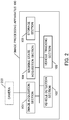
- Fig. 2 is a system configuration diagram of the image processing system according to the present embodiment.
- the image processing apparatus 100 includes an image acquisition section 101, a vehicle detection section 102, a vehicle tracking section 103, a masking state acquisition section 104, and a storage section 105.
- the image acquisition section 101 is a unit configured to acquire an image (hereinafter referred to as a road image) that includes a vehicle traveling on a road by using the camera 200 mounted on the road.
- the image acquisition section 101 can acquire the road images consecutively at a predetermined frame rate.
- the road images acquired by the image acquisition section 101 are stored in the storage section 105 chronologically, and are used in processes performed by the individual units described later.
- the term "frame” is used to mean one of the road images that are consecutively acquired, but the frame is equivalent to the road image.
- the appearance of a new vehicle (a vehicle that is not yet tracked) from outside an imaging area is referred to as flowing in, and the movement of a vehicle that is being tracked out of the imaging area is referred to as flowing out.
- the vehicle detection section 102 is a unit configured to detect that a new vehicle that is not currently tracked flows in the imaging area of the camera 200.
- the detection of the new vehicle can be performed by using a plurality of feature amounts pre-stored in the storage section 105.
- the feature amount may be any feature amount that allows the detection of the vehicle.
- the feature amount that differs according to a vehicle type or a vehicle shape (a passenger car, a truck, a bus, a motorcycle and the like) may be used.
- the feature amounts may be classified arbitrarily.
- the feature amount in the case where the vehicle is viewed in a different direction may be retained for each direction.
- the vehicle detection section 102 is a unit configured to detect the appearance of the new vehicle that is not tracked, and tracking of the vehicle in subsequent frames is performed by the vehicle tracking section 103.
- the vehicle is tracked in the entire imaging area of the camera 200, but the area in which the vehicle is tracked may be determined separately.
- the vehicle tracking section 103 is a unit configured to track the movement of the vehicle detected by the vehicle detection section 102 between a plurality of the frames. The tracking is continued until the vehicle flows out of the imaging area.
- the tracking of the vehicle is performed by using two types of pieces of data of a template image corresponding to a target vehicle to be tracked (hereinafter referred to as a tracking target vehicle) and a masking map generated by the masking state acquisition section 104 described later. The specific details of processes for generating the template image and the masking map will be described later.
- the masking state acquisition section 104 is a unit configured to acquire the masking state of the tracking target vehicle and generate the masking map.
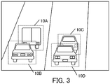
- Fig. 3 is an example of the road image captured by the camera 200.
- the image processing system according to the present embodiment is the system for tracking the vehicle of which the video is shot by the camera installed on a road, and hence the tracking target vehicle is masked by a vehicle in front or behind in many cases.
- vehicles 10A and 10C are masked by following vehicles.
- a conventionally used method such as template matching
- the vehicle 10C almost half of the corresponding area is masked, and hence a score in matching is reduced and tracking can be interrupted accordingly.
- the masking state acquisition section 104 generates the masking map indicative of the degree of masking by another object (vehicle) for each tracking target vehicle, and template matching is performed after weighting is performed based on the masking map.
- a specific generation method of the masking map and a use method of the masking map will be described later.
- the storage section 105 is a unit configured to temporarily or permanently store data that is used by the apparatus.
- a storage medium that is capable of high-speed read and write and has a large capacity.
- a flash memory or the like can be suitably used.
- the storage section 105 temporarily or permanently stores the feature amount used by the vehicle detection section 102, a plurality of images acquired by the image acquisition section 101, the template image used by the vehicle tracking section 103, and the masking map generated by the masking state acquisition section 104.
- the image acquisition section 101, the vehicle detection section 102, the vehicle tracking section 103, and the masking state acquisition section 104 may be implemented by exclusively designed hardware, or may also be implemented by a software module. In the case where they are executed as software, a program stored in an auxiliary storage apparatus is loaded into a main storage apparatus and the program is executed by a CPU, and each unit thereby functions (the CPU, the auxiliary storage apparatus, and the main storage apparatus are not shown).
- FIGs. 4A and 4B are views showing the masking state of the tracking target vehicle and the corresponding masking map.
- the masking map is the map in which an area corresponding to the tracking target vehicle is divided into 16 blocks (4 ⁇ 4), and a value indicative of the degree of masking (masking degree) is assigned to each block.
- the masking degree is represented by real numbers that include 1 indicative of a state in which the tracking target vehicle is completely masked and 0 indicative of a state in which the tracking target vehicle is not masked at all.
- Fig. 4A is an example of the state in which the tracking target vehicle is not masked. In this case, 0 is assigned to each block in the masking map.
- Fig. 4B is an example of the state in which part of the tracking target vehicle is masked by a following vehicle. In this case, values of not less than 0 are assigned to 6 blocks at the lower left.
- the image processing apparatus generates the above masking map for each tracking target vehicle and for each frame, and performs template matching after performing weighting based on the assigned value. That is, a smaller weight is assigned to the masked block, and a larger weight is assigned to the block that is not masked. With this, it is possible to detect the position of the tracking target vehicle while eliminating an effect of masking.
- the masking degree is the real number ranging from 0 to 1, but the masking degree may also be the real number other than the above real number.
- the masking degree does not necessarily range from 0 to 1.
- the masking degree may be an integer ranging from 0 to 255.
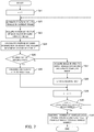
- Fig. 5 serving as a process flowchart. Processing shown in Fig. 5 is executed every time the image acquisition section 101 acquires a new frame. For example, in the case where the frame rate is 10 fps, the processing is executed 10 times per second.
- Step S11 the image acquisition section 101 acquires the road image via the camera 200, and causes the storage section 105 to store the road image temporarily. Note that the acquired road image is stored chronologically, and is deleted when the processing is completed.
- Step S12 the vehicle tracking section 13 determines whether or not a currently tracked vehicle is present and, in the case where the currently tracked vehicle is present, the vehicle tracking section 13 executes a process for tracking the tracking target vehicle. It is determined whether or not the currently tracked vehicle is present by using a counter described later. Note that the description will be made on the assumption that the currently tracked vehicle is not present, and the details of Step S12 will be described later with reference to Fig. 7 .
- Step S13 the vehicle detection section 102 determines whether or not the vehicle that is not currently tracked is present on the image acquired in Step S11. Specifically, the vehicle detection section 102 performs the detection of the vehicle based on the feature amount pre-stored in the storage section 105. In the detection of the vehicle in the present step, it is possible to use a known object detection method based on the feature amount. For example, matching is performed by using a plurality of stored feature amounts, and an initial position and an area are determined. Note that, in the case where the detected vehicle is the currently tracked vehicle, the vehicle is skipped. Information on the currently tracked vehicle is shared by the vehicle detection section 102 and the vehicle tracking section 103 via the storage section 105.
- Step S14 the processing performed on the frame is ended.
- Step S14 the vehicle detection section 102 clips the corresponding area, and uses the area as a template image 601.
- the template image generated herein is used in the tracking of the vehicle in subsequent frames.
- the template image 601 is associated with a vehicle identifier (numbered every time the vehicle is detected), and the area on the image in which the vehicle is detected, and is stored in the storage section 105.
- the vehicle detection section 102 generates a masking map 602 corresponding to the tracking target vehicle.
- the masking map generated herein is the map in which a default value (the masking degree: 0) is set in each block, as shown in Fig. 6B .
- Step S15 the vehicle detection section 102 adds the number of detected vehicles to the number of currently tracked vehicles (hereinafter referred to as a currently tracked vehicle number).
- the number of vehicles set herein is used in a vehicle tracking process executed in Step S12.
- Step S12 the process performed in Step S12 will be described with reference to a flowchart shown in Fig. 7 . Note that it is assumed that each step is executed by the vehicle tracking section 103 unless otherwise specified.
- Step S12 The process in Step S12 is executed in the case where the set "currently tracked vehicle number" is not less than one. That is, at a timing when Step S12 is executed, two or more frames are chronologically stored in the storage section 105.
- Step S21 a counter n is set to 1.
- n is the counter for sequentially performing the process on the tracking target vehicles included in the image.
- Step S22 the rough position of the n-th vehicle included in the image in the current frame is estimated.
- the present step is a process for narrowing an area for performing template matching from the entire area of the image.
- the position in the current frame may be estimated based on the change of the position.
- the change of the position of the target vehicle from the position thereof in the second previous frame to the position thereof in the previous frame may be acquired, and the position of the target vehicle in the current frame may be estimated by using the change.
- the position of the vehicle may also be estimated by using a Kalman filter or the like.
- the target vehicle is positioned in the vicinity of the position detected in Step S13 or in the immediately previous frame, or the narrowing may be omitted.
- Step S23 template matching is performed on the road image by using the template image corresponding to the n-th vehicle.
- the template image is divided into 16 blocks arranged in a 4 ⁇ 4 matrix, and the matching is performed on each block in the vicinity of the position estimated in Step S22.
- a movement vector v block(x, y) (x and y are coordinates) is generated for each of 16 blocks based on the change of the position from that in the previous frame.
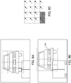
- Fig. 8A is a view showing a frame immediately prior to a currently processed frame
- Fig. 8B is a view showing the currently processed frame.
- Fig. 8C is a view showing the movement vector of each block between the above frames. Note that two hatched blocks are blocks of which the movement vectors are not obtained correctly due to masking. In each of the two blocks, the movement vector is set to 0.
- Step S23 the movement vector of each block between the immediately prior frame and the current frame is acquired.
- Step S24 a single movement vector corresponding to the vehicle is acquired based on the movement vector of each block acquired in Step S23 and the masking map.
- an outlier i.e., a vector having a value that significantly deviates from those of the other vectors is excluded first. For example, a vector having a value that deviates from the average or the mode by 20% or more is excluded.
- the weighting based on the masking map is performed on each of the remaining movement vectors.
- the weight is calculated by using a decreasing function of the masking degree. It is possible to use, e.g., a function (1 - x). That is, 1 is calculated as the weight in the case where the masking degree is 0, 0 is calculated as the weight in the case where the masking degree is 1, and the movement vector is multiplied by the weight.
- the masking map used herein is the map indicative of the masking state of the tracking target vehicle in the previous frame.
- the masking map is set to a default state (i.e., each masking degree is 0), and hence the movement vector does not change.
- the average of a plurality of the movement vectors is calculated, and the average is used as the single movement vector v corresponding to the tracking target vehicle.
- the above acquisition method of the single movement vector is not limited the method that is described above as an example.
- the movement vector corresponding to the block having the largest weight may be used as the single movement vector corresponding to the vehicle, and the average of the movement vectors of the blocks each having the weight of larger than a predetermined threshold value may also be used as the single movement vector corresponding to the vehicle.
- Step S25 it is determined whether or not the tracking target vehicle has flowed out of the imaging area.
- the determination may be affirmative in the case where the tracking target vehicle has flowed out of the area.
- the determination may also be affirmative in the case where the tracking has resulted in failure or has resulted in failure consecutively the number of times equal to the predetermined number of frames.
- a tracking end flag of the n-th vehicle is set to true, and the process transitions to Step S29.
- an area to which the vehicle has moved is clipped, and the area is set as a new template image (Step S27).
- an image corresponding to an area 801 is reset as the template image.
- the size of the area may be equal to that in the previous frame, or may be appropriately adjusted.
- a method in which the area is enlarged or reduced based on a predetermined coefficient, and a method in which the size thereof is enlarged or reduced based on detected change of a distance between blocks are available.
- Step S28 the masking state acquisition section 104 updates the masking map.
- a difference represented by ⁇ P (x, y)
- a process for setting the masking degree assigned to each block back to 0 is performed. For example, in the case where (1) the masking degree is not less than a predetermined value and (2)
- the counter n is incremented in Step S29, and it is determined whether or not the counter n exceeds the currently tracked vehicle number in Step S30. As a result, in the case where the counter n does not exceed the currently tracked vehicle number, the process returns to Step S22, and the tracking of the next vehicle is started. In the case where the counter n exceeds the currently tracked vehicle number, the number of vehicles of which the tracking is ended (the number of vehicles of which the tracking end flags are set to true) is subtracted from the currently tracked vehicle number (Step S31).
- the masking map is updated at any time as the processing of the frame progresses. With this, it is possible to use the masking map obtained when the i-th frame is processed in the processing of the i + 1-th frame. With this, it is possible to reflect the masking state that ceaselessly changes with the passage of time at any time. That is, even in the case where the masking occurs dynamically in consecutive frames, it is possible to appropriately update the masking map.
- the present embodiment describes the example in which the updated masking map is used in the weighting in the process in the next frame, but the updated masking map does not necessarily need to be used in the process in the next frame. That is, the target frame may be changed appropriately within a range in which the effects of the invention are obtained.
- the masking map updated in the i-th frame may be used in the processing of the i + 2-th frame.
- the masking map updated in the i-th frame may be used in the processing of the i + 1-th to i + 10-th frames.
- the image processing apparatus generates the masking map based on the result of the comparison between the movement vector acquired for each block and the movement vector corresponding to the entire vehicle, and performs the weighting when matching is performed by using the masking map. It is not possible to positively eliminate the effect of the masking in template matching in conventional arts, but the image processing apparatus according to the present embodiment can perform the matching while reducing the effect of the block that exerts an adverse effect by performing the weighting described above. That is, it is possible to improve accuracy in the tracking of the vehicle.
- a second embodiment is an embodiment in which the masking degree is corrected based on the strength of an edge on the image.
- the strength of an edge present in a direction perpendicular to the traveling direction of the vehicle is extracted, a coefficient proportional to the strength of the edge is calculated, and the masking degree is multiplied by the coefficient.
- a Sobel filter that extracts the edge present in the direction perpendicular to the traveling direction of the vehicle (a horizontal axis direction in the example in Figs. 8A to 8C ) is applied to the acquired image, and the sum of absolute values of all obtained values is acquired.
- the masking degree in the masking map is multiplied by a coefficient determined by using a relation shown in Fig. 9 .
- the vehicle traveling in a specific direction in the image has a characteristic that an edge occurs in a direction orthogonal to the traveling direction.
- the traveling direction of the vehicle may be defined in advance, and may also be dynamically set according to a detection result by providing a detection unit. For example, learning may be performed based on the previous tracking result, and the traveling direction of the vehicle may be estimated accordingly.
- the tracking target vehicle is divided into 16 blocks and the process is performed, but the division method may be the method other than the above method.
- the division method may be the method other than the above method.
- the number of blocks is increased, the accuracy is improved, but process time is increased, and hence the number of blocks and the size of the block may be appropriately set based on required specifications.
- the masking map is generated by determining the difference between the movement vector corresponding to the vehicle and each of the 16 movement vectors, but the calculation method of the masking degree is not limited to the method described as the example as long as the masking degree can be determined by the method.
- the example in which the vehicle is tracked by processing a plurality of consecutively acquired frames one by one is described, but the frames do not necessarily need to be processed one by one. For example, it is also possible to thin out the frames and process every other frame.
Landscapes
- Engineering & Computer Science (AREA)
- Physics & Mathematics (AREA)
- General Physics & Mathematics (AREA)
- Multimedia (AREA)
- Computer Vision & Pattern Recognition (AREA)
- Theoretical Computer Science (AREA)
- Image Analysis (AREA)
- Image Processing (AREA)
- Traffic Control Systems (AREA)
Abstract
Description
- The present invention relates to a technique for tracking an object included in consecutive frames.
- In a monitoring system or the like, there is known a technique for detecting an object included in an image and automatically tracking the movement of the object. The tracking of the object can be implemented by, e.g., acquiring a difference between an image that does not include a target object to be tracked and an image that includes the target object to be tracked to generate a template, and searching the image frame by frame by using the template (PTL 1).
- As a system to which the tracking of the object is applied, a traffic flow measurement system is known. It is possible to count the number of vehicles having passed a target point by shooting a video of a road by using, e.g., a camera installed on the roadside and tracking passing vehicles (PTL 2).
-
- [PTL 1] Japanese Patent Application Publication No.
2001-060269 - [PTL 2] Japanese Patent Application Publication No.
2009-087316 - When a vehicle passing on a road is tracked based on the image (video) of the road, there are cases where masking becomes a problem. For example, when a distance between vehicles is short, there are cases where the vehicles overlap each other on the image. In addition, there are cases where vehicles in adjacent lanes overlap each other due to a lane change or the like. Thus, when part of a target vehicle to be tracked is masked by another object (a vehicle or the like), a problem arises in that accuracy in template matching is significantly reduced.
- In the invention described in
PTL 1, by performing matching by using a plurality of templates acquired at different times and using the template having the highest degree of matching, a reduction in tracking accuracy is prevented. However, in the case where a vehicle on a road is tracked, there are cases where the target vehicle to be tracked is widely masked by a vehicle in front or behind and, in these cases, it is not possible to maintain the accuracy by this method. - The invention described in PTL 2 adopts a method in which a possibility that tracking is correctly performed is verified after vehicles on a road are individually tracked, and the final result is determined based on the possibility. However, in the case where a target vehicle is widely masked or the case where a plurality of vehicles exhibit complicated behavior, it is not possible to maintain the accuracy similarly.
- The present invention has been made in view of the above problem, and an object thereof is to improve accuracy in tracking in the case where part of a target object to be tracked is masked in an image processing device for tracking an object.
- The present invention in its one aspect provides an image processing device for tracking a target object to be tracked included in a plurality of consecutively captured images, the image processing device comprising an image acquisition unit configured to acquire an image; a template acquisition unit configured to acquire a template corresponding to a target object to be tracked included in the image; a masking map generation unit configured to generate a masking map serving as a map indicative of a degree of masking the target object to be tracked, which is included in the image, by another object; and a tracking unit configured to detect the target object to be tracked included in the image by using the template, and acquire over a plurality of images an amount of movement of the target object to be tracked and a direction of the movement of the target object to be tracked, based on both of the template and the masking map.
- The image processing device according to the present invention is the apparatus for tracking the movement of the target object to be tracked between a plurality of frames. Note that the movement denotes movement on the image, and the movement can occur due to the movement of the target object to be tracked and the change of shooting conditions (pan, tilt, and zoom of a camera).
- The template acquisition unit is the unit configured to acquire the template corresponding to the target object to be tracked. The template may be a feature amount of the target object to be tracked, and may also be an image of the target object to be tracked. For example, in the case where a vehicle is tracked, the feature amount of each vehicle type (e.g., a passenger car, a truck, a bus, or a motorcycle) may be used and, in the case where the result of previous tracking is present, the image cut out based on the tracking result may be used.
- The masking map generation unit is the unit configured to generate the map (masking map) indicative of the degree of masking of the target object to be tracked by another object. The masking map may be the map in which an area corresponding to the target object to be tracked is divided into a plurality of blocks. In addition, the masking degree may be represented by using an unlimited number of levels.
- In addition, the tracking unit is the unit configured to track the target object to be tracked included in the acquired image over a plurality of consecutively acquired frames. In the present invention, the tracking unit tracks the movement of the target object to be tracked between the frames by using not only the template corresponding to the target object to be tracked but also the masking map. In the case where part of the target object to be tracked is masked, accuracy in tracking by matching is reduced in accordance with the ratio of the masking, but it becomes possible to perform the matching in consideration of the masking by another object by using the masking map, and the accuracy in tracking is improved.
- Also, the masking map may be a map in which the template is divided into a plurality of blocks and the degree of masking is associated with each of the blocks, and the tracking unit may acquire the amount of the movement of the target object to be tracked and the direction of the movement of the target object to be tracked based on a result of matching performed by using the template on a per block basis and weighting performed by using the degree of masking corresponding to each of the blocks.
- By performing the weighting on a matching result based on the masking degree of each block, it is possible to acquire an area to which the target object to be tracked has moved with high accuracy while reducing the effect of the masked block.
- Also, the masking map generation unit may generate the masking map, based on a result of a comparison between a single vector, obtained by tracking the target object to be tracked over the plurality of images, and each of a plurality of vectors obtained by tracking the plurality of blocks over the plurality of images.
- It is possible to generate the masking condition of the target object to be tracked by comparing "the single vector corresponding to the entire target object to be tracked" with "the plurality of vectors corresponding to the plurality of blocks constituting the target object to be tracked on a one-to-one basis". In the case where the masking occurs in one block, the accuracy in tracking over the frames is reduced in the block (or the tracking results in failure). Therefore, it is possible to calculate the masking degree in the block based on a displacement between the vectors.
- Also, the masking map generation unit may set the degree of masking a corresponding block to a higher degree of masking as a difference between the single vector and each of the plurality of vectors resulting from the comparison between the single vector and each of the plurality of vectors is larger, and the tracking unit may set, as the degree of masking corresponding to a block is higher, a weight of the block to a smaller weight.
- Also, the masking map generation unit may update the masking map every time the tracking unit generates a tracking result, and the tracking unit may use the updated masking map in a process of detecting the target object to be tracked in a next frame.
- The masking condition of the target object to be tracked changes depending on the frame. Therefore, the masking condition of the target object to be tracked in the previous frame may be used in the tracking in the next frame. With this, it is possible to cope with the case where the masking condition changes ceaselessly.
- Also, the degree of masking set in the masking map may be lower as an edge perpendicular to the movement direction of the target object to be tracked in a corresponding block is stronger.
- In the case where the target object to be tracked moves in a specific direction, and a strong edge perpendicular to the movement direction is observed, it can be presumed that the target object to be tracked is not masked. Therefore, the masking map may be corrected by using the strength of the edge.
- Also, the template acquisition unit may use an image obtained by clipping the target object to be tracked, which has been detected by the tracking unit, as the template in the next frame.
- In the case where the result of detection of the target object to be tracked is present, an image serving as the template may be acquired based on the result, and the image may be used in the next frame. According to the configuration described above, even in the case where the size or orientation of the target object to be tracked gradually changes with the passage of time, it is possible to track the target object to be tracked accurately.
- Note that the present invention can be viewed as an image processing device that includes at least part of the above units. In addition, the present invention can also be viewed as an image processing method executed by the above image processing device. Further, the present invention can also be viewed as a program that causes a computer to execute the above image processing method. The above processes and units can be arbitrarily combined and implemented as long as no technical conflicts occur.
- According to the present invention, in the image processing device for tracking the object, it is possible to improve the accuracy in tracking in the case where part of the target object to be tracked is masked.
-
-
Fig. 1 is a layout of an image processing system according to a first embodiment. -
Fig. 2 is a configuration diagram of the image processing system according to the first embodiment. -
Fig. 3 is an example of an image acquired by an image acquisition section. -
Figs. 4A and 4B are views for explaining masking of a preceding vehicle by a following vehicle, and a masking map. -
Fig. 5 is a flowchart of processing performed by an image processing apparatus according to the first embodiment. - [
Fig. 6] Figs. 6A and 6B are views for explaining a vehicle detection process. -
Fig. 7 is a flowchart of the processing performed by the image processing apparatus according to the first embodiment. -
Figs. 8A to 8C are views for explaining a vehicle tracking process. -
Fig. 9 is a view for explaining the strength of an edge in a second embodiment. - Hereinbelow, preferred embodiments of the present invention will be described with reference to the drawings.
- An image processing system according to the present embodiment is a system that consecutively acquires images of a vehicle traveling on a road, and tracks the movement of the vehicle based on a plurality of the acquired images.
-
Fig. 1 is a layout of the image processing system according to the present embodiment. The image processing system according to the present embodiment includes an image processing apparatus 100 and acamera 200, and the image processing apparatus 100 processes a plurality of images consecutively captured by thecamera 200 disposed on a road to track the movement of a vehicle. -
Fig. 2 is a system configuration diagram of the image processing system according to the present embodiment. - The image processing apparatus 100 includes an
image acquisition section 101, avehicle detection section 102, avehicle tracking section 103, a maskingstate acquisition section 104, and astorage section 105. - The
image acquisition section 101 is a unit configured to acquire an image (hereinafter referred to as a road image) that includes a vehicle traveling on a road by using thecamera 200 mounted on the road. Theimage acquisition section 101 can acquire the road images consecutively at a predetermined frame rate. The road images acquired by theimage acquisition section 101 are stored in thestorage section 105 chronologically, and are used in processes performed by the individual units described later. - Note that, in the description of the embodiments, the term "frame" is used to mean one of the road images that are consecutively acquired, but the frame is equivalent to the road image. In addition, in consecutive frames, the appearance of a new vehicle (a vehicle that is not yet tracked) from outside an imaging area is referred to as flowing in, and the movement of a vehicle that is being tracked out of the imaging area is referred to as flowing out.
- The
vehicle detection section 102 is a unit configured to detect that a new vehicle that is not currently tracked flows in the imaging area of thecamera 200. The detection of the new vehicle can be performed by using a plurality of feature amounts pre-stored in thestorage section 105. The feature amount may be any feature amount that allows the detection of the vehicle. For example, the feature amount that differs according to a vehicle type or a vehicle shape (a passenger car, a truck, a bus, a motorcycle and the like) may be used. In the case where a plurality of the feature amounts are used, the feature amounts may be classified arbitrarily. Further, the feature amount in the case where the vehicle is viewed in a different direction (the front, rear, left, right and the like) may be retained for each direction. - The
vehicle detection section 102 is a unit configured to detect the appearance of the new vehicle that is not tracked, and tracking of the vehicle in subsequent frames is performed by thevehicle tracking section 103. - Note that, in the present embodiment, it is assumed that the vehicle is tracked in the entire imaging area of the
camera 200, but the area in which the vehicle is tracked may be determined separately. - The
vehicle tracking section 103 is a unit configured to track the movement of the vehicle detected by thevehicle detection section 102 between a plurality of the frames. The tracking is continued until the vehicle flows out of the imaging area. The tracking of the vehicle is performed by using two types of pieces of data of a template image corresponding to a target vehicle to be tracked (hereinafter referred to as a tracking target vehicle) and a masking map generated by the maskingstate acquisition section 104 described later. The specific details of processes for generating the template image and the masking map will be described later. - The masking
state acquisition section 104 is a unit configured to acquire the masking state of the tracking target vehicle and generate the masking map. - Herein, the masking state and the masking map will be described.
Fig. 3 is an example of the road image captured by thecamera 200. The image processing system according to the present embodiment is the system for tracking the vehicle of which the video is shot by the camera installed on a road, and hence the tracking target vehicle is masked by a vehicle in front or behind in many cases. - For example, in the example in
Fig. 3 ,vehicles vehicle 10C, almost half of the corresponding area is masked, and hence a score in matching is reduced and tracking can be interrupted accordingly. - To cope with this, in the image processing apparatus according to the present embodiment, the masking
state acquisition section 104 generates the masking map indicative of the degree of masking by another object (vehicle) for each tracking target vehicle, and template matching is performed after weighting is performed based on the masking map. A specific generation method of the masking map and a use method of the masking map will be described later. - The
storage section 105 is a unit configured to temporarily or permanently store data that is used by the apparatus. As thestorage section 105, it is preferable to use a storage medium that is capable of high-speed read and write and has a large capacity. For example, a flash memory or the like can be suitably used. Thestorage section 105 temporarily or permanently stores the feature amount used by thevehicle detection section 102, a plurality of images acquired by theimage acquisition section 101, the template image used by thevehicle tracking section 103, and the masking map generated by the maskingstate acquisition section 104. - Note that the
image acquisition section 101, thevehicle detection section 102, thevehicle tracking section 103, and the maskingstate acquisition section 104 may be implemented by exclusively designed hardware, or may also be implemented by a software module. In the case where they are executed as software, a program stored in an auxiliary storage apparatus is loaded into a main storage apparatus and the program is executed by a CPU, and each unit thereby functions (the CPU, the auxiliary storage apparatus, and the main storage apparatus are not shown). - Next, the details of the masking map generated by the masking
state acquisition section 104 will be described.Figs. 4A and 4B are views showing the masking state of the tracking target vehicle and the corresponding masking map. - The masking map is the map in which an area corresponding to the tracking target vehicle is divided into 16 blocks (4 × 4), and a value indicative of the degree of masking (masking degree) is assigned to each block. Note that the masking degree is represented by real numbers that include 1 indicative of a state in which the tracking target vehicle is completely masked and 0 indicative of a state in which the tracking target vehicle is not masked at all.
-
Fig. 4A is an example of the state in which the tracking target vehicle is not masked. In this case, 0 is assigned to each block in the masking map.Fig. 4B is an example of the state in which part of the tracking target vehicle is masked by a following vehicle. In this case, values of not less than 0 are assigned to 6 blocks at the lower left. - The image processing apparatus according to the present embodiment generates the above masking map for each tracking target vehicle and for each frame, and performs template matching after performing weighting based on the assigned value. That is, a smaller weight is assigned to the masked block, and a larger weight is assigned to the block that is not masked. With this, it is possible to detect the position of the tracking target vehicle while eliminating an effect of masking.
- The specific generation method of the masking map will be described later. In the present example, the masking degree is the real number ranging from 0 to 1, but the masking degree may also be the real number other than the above real number. In addition, the masking degree does not necessarily range from 0 to 1. For example, the masking degree may be an integer ranging from 0 to 255.
- Next, the details of image processing performed by the image processing apparatus 100 will be described with reference to
Fig. 5 serving as a process flowchart. Processing shown inFig. 5 is executed every time theimage acquisition section 101 acquires a new frame. For example, in the case where the frame rate is 10 fps, the processing is executed 10 times per second. - First, in Step S11, the
image acquisition section 101 acquires the road image via thecamera 200, and causes thestorage section 105 to store the road image temporarily. Note that the acquired road image is stored chronologically, and is deleted when the processing is completed. - Next, in Step S12, the
vehicle tracking section 13 determines whether or not a currently tracked vehicle is present and, in the case where the currently tracked vehicle is present, thevehicle tracking section 13 executes a process for tracking the tracking target vehicle. It is determined whether or not the currently tracked vehicle is present by using a counter described later. Note that the description will be made on the assumption that the currently tracked vehicle is not present, and the details of Step S12 will be described later with reference toFig. 7 . - In Step S13, the
vehicle detection section 102 determines whether or not the vehicle that is not currently tracked is present on the image acquired in Step S11. Specifically, thevehicle detection section 102 performs the detection of the vehicle based on the feature amount pre-stored in thestorage section 105. In the detection of the vehicle in the present step, it is possible to use a known object detection method based on the feature amount. For example, matching is performed by using a plurality of stored feature amounts, and an initial position and an area are determined. Note that, in the case where the detected vehicle is the currently tracked vehicle, the vehicle is skipped. Information on the currently tracked vehicle is shared by thevehicle detection section 102 and thevehicle tracking section 103 via thestorage section 105. - Herein, it is assumed that a new vehicle is detected in an
image 600 shown inFig. 6A . - When the new vehicle is detected, the processing transitions to Step S14. In the case where the new vehicle is not detected, the processing performed on the frame is ended.
- When the vehicle is detected, in Step S14, the
vehicle detection section 102 clips the corresponding area, and uses the area as atemplate image 601. The template image generated herein is used in the tracking of the vehicle in subsequent frames. Thetemplate image 601 is associated with a vehicle identifier (numbered every time the vehicle is detected), and the area on the image in which the vehicle is detected, and is stored in thestorage section 105. In addition, thevehicle detection section 102 generates amasking map 602 corresponding to the tracking target vehicle. The masking map generated herein is the map in which a default value (the masking degree: 0) is set in each block, as shown inFig. 6B . - Next, in Step S15, the
vehicle detection section 102 adds the number of detected vehicles to the number of currently tracked vehicles (hereinafter referred to as a currently tracked vehicle number). The number of vehicles set herein is used in a vehicle tracking process executed in Step S12. - Next, the process performed in Step S12 will be described with reference to a flowchart shown in
Fig. 7 . Note that it is assumed that each step is executed by thevehicle tracking section 103 unless otherwise specified. - The process in Step S12 is executed in the case where the set "currently tracked vehicle number" is not less than one. That is, at a timing when Step S12 is executed, two or more frames are chronologically stored in the
storage section 105. - First, in Step S21, a counter n is set to 1. n is the counter for sequentially performing the process on the tracking target vehicles included in the image.
- Next, in Step S22, the rough position of the n-th vehicle included in the image in the current frame is estimated. The present step is a process for narrowing an area for performing template matching from the entire area of the image. For example, in the case where the change of the position of the n-th vehicle is determined in two or more previous frames, the position in the current frame may be estimated based on the change of the position. For example, the change of the position of the target vehicle from the position thereof in the second previous frame to the position thereof in the previous frame may be acquired, and the position of the target vehicle in the current frame may be estimated by using the change. In addition, the position of the vehicle may also be estimated by using a Kalman filter or the like.
- Note that, in the case where sufficient information for performing the estimation is not provided, it may be presumed that the target vehicle is positioned in the vicinity of the position detected in Step S13 or in the immediately previous frame, or the narrowing may be omitted.
- Next, in Step S23, template matching is performed on the road image by using the template image corresponding to the n-th vehicle.
- Note that, in this step, the template image is divided into 16 blocks arranged in a 4 × 4 matrix, and the matching is performed on each block in the vicinity of the position estimated in Step S22. As a result, since 16 matching results are obtained, a movement vector vblock(x, y) (x and y are coordinates) is generated for each of 16 blocks based on the change of the position from that in the previous frame.
-
Fig. 8A is a view showing a frame immediately prior to a currently processed frame, andFig. 8B is a view showing the currently processed frame. - In addition,
Fig. 8C is a view showing the movement vector of each block between the above frames. Note that two hatched blocks are blocks of which the movement vectors are not obtained correctly due to masking. In each of the two blocks, the movement vector is set to 0. - When the process in Step S23 is completed, the movement vector of each block between the immediately prior frame and the current frame is acquired.
- In Step S24, a single movement vector corresponding to the vehicle is acquired based on the movement vector of each block acquired in Step S23 and the masking map.
- Specifically, from among 16 movement vectors, an outlier, i.e., a vector having a value that significantly deviates from those of the other vectors is excluded first. For example, a vector having a value that deviates from the average or the mode by 20% or more is excluded.
- Next, the weighting based on the masking map is performed on each of the remaining movement vectors. Specifically, the weight is calculated by using a decreasing function of the masking degree. It is possible to use, e.g., a function (1 - x). That is, 1 is calculated as the weight in the case where the masking degree is 0, 0 is calculated as the weight in the case where the masking degree is 1, and the movement vector is multiplied by the weight.
- The masking map used herein is the map indicative of the masking state of the tracking target vehicle in the previous frame. In the initial process, the masking map is set to a default state (i.e., each masking degree is 0), and hence the movement vector does not change.
- Lastly, the average of a plurality of the movement vectors is calculated, and the average is used as the single movement vector v corresponding to the tracking target vehicle.
- Note that the above acquisition method of the single movement vector is not limited the method that is described above as an example. For example, the movement vector corresponding to the block having the largest weight may be used as the single movement vector corresponding to the vehicle, and the average of the movement vectors of the blocks each having the weight of larger than a predetermined threshold value may also be used as the single movement vector corresponding to the vehicle.
- In Step S25, it is determined whether or not the tracking target vehicle has flowed out of the imaging area. Note that, in the case where a tracking area is set on the image, the determination may be affirmative in the case where the tracking target vehicle has flowed out of the area. In addition, the determination may also be affirmative in the case where the tracking has resulted in failure or has resulted in failure consecutively the number of times equal to the predetermined number of frames. In the case where it is determined that the tracking target vehicle has flowed out of the imaging area, a tracking end flag of the n-th vehicle is set to true, and the process transitions to Step S29.
- In the case where the tracking target vehicle is in the imaging area, an area to which the vehicle has moved is clipped, and the area is set as a new template image (Step S27). In the case of an example in
Figs. 8A to 8C , an image corresponding to anarea 801 is reset as the template image. When the area is clipped, the size of the area may be equal to that in the previous frame, or may be appropriately adjusted. In the case where the size of the area is adjusted, a method in which the area is enlarged or reduced based on a predetermined coefficient, and a method in which the size thereof is enlarged or reduced based on detected change of a distance between blocks are available. - Next, in Step S28, the masking
state acquisition section 104 updates the masking map. - Specifically, a difference (represented by ΔP(x, y)) between the movement vector v corresponding to the vehicle and each of the 16 movement vectors vblock(x, y) is acquired, and a value (k|ΔP(x, y)|) obtained by multiplying the absolute value of ΔP(x, y) by a constant k is added to each of current values set in the masking map. That is, the masking degree of each block of the masking map is 0 + k|ΔP(x, y)| in the initial process.
- In the case of the example in
Figs. 8A to 8C , two blocks at the lower left are masked by the following vehicle, and hence only the two blocks at the lower left are updated with the masking degrees higher than those of the other blocks. - Note that, in the case where it is determined that the masking has disappeared, a process for setting the masking degree assigned to each block back to 0 is performed. For example, in the case where (1) the masking degree is not less than a predetermined value and (2) |ΔP(x, y)| is not more than a predetermined value, it may be determined that the masking has disappeared. It will be easily understood that other methods may also be adopted.
- With this, the tracking process performed on the n-th vehicle is ended.
- The counter n is incremented in Step S29, and it is determined whether or not the counter n exceeds the currently tracked vehicle number in Step S30. As a result, in the case where the counter n does not exceed the currently tracked vehicle number, the process returns to Step S22, and the tracking of the next vehicle is started. In the case where the counter n exceeds the currently tracked vehicle number, the number of vehicles of which the tracking is ended (the number of vehicles of which the tracking end flags are set to true) is subtracted from the currently tracked vehicle number (Step S31).
- Note that the updated masking map is used in the weighting in the process in the next frame.
- In addition, the masking map is updated at any time as the processing of the frame progresses. With this, it is possible to use the masking map obtained when the i-th frame is processed in the processing of the i + 1-th frame. With this, it is possible to reflect the masking state that ceaselessly changes with the passage of time at any time. That is, even in the case where the masking occurs dynamically in consecutive frames, it is possible to appropriately update the masking map.
- Note that the present embodiment describes the example in which the updated masking map is used in the weighting in the process in the next frame, but the updated masking map does not necessarily need to be used in the process in the next frame. That is, the target frame may be changed appropriately within a range in which the effects of the invention are obtained.
- For example, the masking map updated in the i-th frame may be used in the processing of the i + 2-th frame. In addition, for example, after the masking map is configured to be updated every 10 frames, the masking map updated in the i-th frame may be used in the processing of the i + 1-th to i + 10-th frames.
- As described above, the image processing apparatus according to the present embodiment generates the masking map based on the result of the comparison between the movement vector acquired for each block and the movement vector corresponding to the entire vehicle, and performs the weighting when matching is performed by using the masking map. It is not possible to positively eliminate the effect of the masking in template matching in conventional arts, but the image processing apparatus according to the present embodiment can perform the matching while reducing the effect of the block that exerts an adverse effect by performing the weighting described above. That is, it is possible to improve accuracy in the tracking of the vehicle.
- A second embodiment is an embodiment in which the masking degree is corrected based on the strength of an edge on the image.
- In the second embodiment, in the process in Step S28, the strength of an edge present in a direction perpendicular to the traveling direction of the vehicle is extracted, a coefficient proportional to the strength of the edge is calculated, and the masking degree is multiplied by the coefficient. For example, a Sobel filter that extracts the edge present in the direction perpendicular to the traveling direction of the vehicle (a horizontal axis direction in the example in
Figs. 8A to 8C ) is applied to the acquired image, and the sum of absolute values of all obtained values is acquired. Subsequently, the masking degree in the masking map is multiplied by a coefficient determined by using a relation shown inFig. 9 . - In the case where the masking does not occur, the vehicle traveling in a specific direction in the image has a characteristic that an edge occurs in a direction orthogonal to the traveling direction. In the second embodiment, it becomes possible to calculate the masking degree more accurately by using the characteristic.
- Note that the traveling direction of the vehicle may be defined in advance, and may also be dynamically set according to a detection result by providing a detection unit. For example, learning may be performed based on the previous tracking result, and the traveling direction of the vehicle may be estimated accordingly.
- Each of the above-described embodiments is only exemplary, and the present invention can be appropriately modified and implemented without departing from the gist thereof.
- For example, in the description of the embodiments, the tracking target vehicle is divided into 16 blocks and the process is performed, but the division method may be the method other than the above method. As the number of blocks is increased, the accuracy is improved, but process time is increased, and hence the number of blocks and the size of the block may be appropriately set based on required specifications.
- In addition, in the description of the embodiments, the masking map is generated by determining the difference between the movement vector corresponding to the vehicle and each of the 16 movement vectors, but the calculation method of the masking degree is not limited to the method described as the example as long as the masking degree can be determined by the method.
- Further, in the description of the embodiments, the example in which the vehicle is tracked by processing a plurality of consecutively acquired frames one by one is described, but the frames do not necessarily need to be processed one by one. For example, it is also possible to thin out the frames and process every other frame.
-
- 100
- Image processing apparatus
- 101
- Image acquisition section
- 102
- Vehicle detection section
- 103
- Vehicle tracking section
- 104
- Masking state acquisition section
- 105
- Storage section
- 200
- Camera
Claims (9)
- An image processing apparatus for tracking a target object to be tracked included in a plurality of consecutively captured images,
the image processing apparatus comprising:an image acquisition unit configured to acquire an image;a template acquisition unit configured to acquire a template corresponding to a target object to be tracked included in the image;a masking map generation unit configured to generate a masking map serving as a map indicative of a degree of masking the target object to be tracked, which is included in the image, by another object; anda tracking unit configured to detect the target object to be tracked included in the image by using the template, and acquire over a plurality of images an amount of movement of the target object to be tracked and a direction of the movement of the target object to be tracked, based on both of the template and the masking map. - The image processing apparatus according to Claim 1, wherein
the masking map is a map in which the template is divided into a plurality of blocks and the degree of masking is associated with each of the blocks, and
the tracking unit acquires the amount of the movement of the target object to be tracked and the direction of the movement of the target object to be tracked based on a result of matching performed by using the template on a per block basis and weighting performed by using the degree of masking corresponding to each of the blocks. - The image processing apparatus according to Claim 2, wherein
the masking map generation unit generates the masking map, based on a result of a comparison between a single vector, obtained by tracking the target object to be tracked over the plurality of images, and each of a plurality of vectors obtained by tracking the plurality of blocks over the plurality of images. - The image processing apparatus according to Claim 3, wherein
the masking map generation unit sets the degree of masking a corresponding block to a higher degree of masking as a difference between the single vector and each of the plurality of vectors resulting from the comparison between the single vector and each of the plurality of vectors is larger, and
the tracking unit sets, as the degree of masking corresponding to a block is higher, a weight of the block to a smaller weight. - The image processing apparatus according to any one of Claims 1 to 4, wherein
the masking map generation unit updates the masking map every time the tracking unit generates a tracking result, and
the tracking unit uses the updated masking map in a process of detecting the target object to be tracked in a next frame. - The image processing apparatus according to any one of Claims 1 to 5, wherein
the degree of masking set in the masking map is lower as an edge perpendicular to the movement direction of the target object to be tracked in a corresponding block is stronger. - The image processing apparatus according to any one of Claims 1 to 6, wherein
the template acquisition unit uses an image obtained by clipping the target object to be tracked, which has been detected by the tracking unit, as the template in the next frame. - An image processing method performed by an image processing apparatus for tracking a target object to be tracked included in a plurality of consecutively captured images,
the image processing method comprising:an image acquisition step of acquiring an image;a template acquisition step of acquiring a template corresponding to a target object to be tracked included in the image;a masking map generation step of generating a masking map serving as a map indicative of a degree masking the target object to be tracked, which is included in the image, by another object; anda tracking step of detecting the target object to be tracked included in the image by using the template and acquiring over a plurality of the images an amount of movement of the target object to be tracked and a direction of the movement of the target object to be tracked, based on both of the template and the masking map. - A computer program for causing a computer to perform the image processing method according to claim 8.
Applications Claiming Priority (2)
| Application Number | Priority Date | Filing Date | Title |
|---|---|---|---|
| JP2016136130A JP6439757B2 (en) | 2016-07-08 | 2016-07-08 | Image processing apparatus and image processing method |
| PCT/JP2017/007312 WO2018008184A1 (en) | 2016-07-08 | 2017-02-27 | Image processing device and image processing method |
Publications (3)
| Publication Number | Publication Date |
|---|---|
| EP3483834A1 true EP3483834A1 (en) | 2019-05-15 |
| EP3483834A4 EP3483834A4 (en) | 2020-02-26 |
| EP3483834B1 EP3483834B1 (en) | 2021-09-22 |
Family
ID=60912433
Family Applications (1)
| Application Number | Title | Priority Date | Filing Date |
|---|---|---|---|
| EP17823793.9A Active EP3483834B1 (en) | 2016-07-08 | 2017-02-27 | Image processing device and image processing method |
Country Status (6)
| Country | Link |
|---|---|
| US (1) | US10497133B2 (en) |
| EP (1) | EP3483834B1 (en) |
| JP (1) | JP6439757B2 (en) |
| KR (1) | KR102011231B1 (en) |
| CN (1) | CN107924568B (en) |
| WO (1) | WO2018008184A1 (en) |
Families Citing this family (6)
| Publication number | Priority date | Publication date | Assignee | Title |
|---|---|---|---|---|
| WO2017170087A1 (en) * | 2016-03-31 | 2017-10-05 | 日本電気株式会社 | Image detection device, image detection method and storage medium storing program |
| CN109816701B (en) * | 2019-01-17 | 2021-07-27 | 北京市商汤科技开发有限公司 | A target tracking method and device, and storage medium |
| JP7630935B2 (en) * | 2020-07-17 | 2025-02-18 | キヤノン株式会社 | Information processing device, information processing method, and program |
| JP7549509B2 (en) * | 2020-10-21 | 2024-09-11 | 株式会社Subaru | Object estimation device, object estimation method, and vehicle |
| CN112330717B (en) * | 2020-11-11 | 2023-03-10 | 北京市商汤科技开发有限公司 | Target tracking method and device, electronic device and storage medium |
| WO2023089706A1 (en) * | 2021-11-17 | 2023-05-25 | 日本電信電話株式会社 | Image processing device, image processing method, and program |
Family Cites Families (15)
| Publication number | Priority date | Publication date | Assignee | Title |
|---|---|---|---|---|
| US6687386B1 (en) * | 1999-06-15 | 2004-02-03 | Hitachi Denshi Kabushiki Kaisha | Object tracking method and object tracking apparatus |
| JP3768073B2 (en) | 1999-06-15 | 2006-04-19 | 株式会社日立国際電気 | Object tracking method and object tracking apparatus |
| JP4469980B2 (en) * | 2004-12-21 | 2010-06-02 | 国立大学法人静岡大学 | Image processing method for tracking moving objects |
| JP2008042659A (en) * | 2006-08-08 | 2008-02-21 | Sony Corp | Image processing apparatus and method, program, and program storage medium |
| KR20080073933A (en) * | 2007-02-07 | 2008-08-12 | 삼성전자주식회사 | Object tracking method and apparatus, and object pose information calculation method and apparatus |
| JP4775277B2 (en) * | 2007-02-07 | 2011-09-21 | 株式会社デンソー | Image processing apparatus and image processing method |
| JP4884331B2 (en) * | 2007-08-20 | 2012-02-29 | セコム株式会社 | Moving object tracking device |
| JP5128339B2 (en) | 2007-09-11 | 2013-01-23 | 株式会社日立製作所 | Traffic flow measurement system |
| JP2009199417A (en) * | 2008-02-22 | 2009-09-03 | Denso Corp | Face tracking device and face tracking method |
| US9349189B2 (en) * | 2013-07-01 | 2016-05-24 | Here Global B.V. | Occlusion resistant image template matching using distance transform |
| CN104794733B (en) * | 2014-01-20 | 2018-05-08 | 株式会社理光 | Method for tracing object and device |
| CN104091348B (en) * | 2014-05-19 | 2017-04-05 | 南京工程学院 | The multi-object tracking method of fusion marked feature and piecemeal template |
| CN105469380A (en) * | 2014-09-05 | 2016-04-06 | 株式会社理光 | Method and device for detecting shielding against object |
| CN105654515A (en) * | 2016-01-11 | 2016-06-08 | 上海应用技术学院 | Target tracking method based on fragmentation and multiple cues adaptive fusion |
| CN105678809A (en) * | 2016-01-12 | 2016-06-15 | 湖南优象科技有限公司 | Handheld automatic follow shot device and target tracking method thereof |
-
2016
- 2016-07-08 JP JP2016136130A patent/JP6439757B2/en active Active
-
2017
- 2017-02-27 US US15/756,084 patent/US10497133B2/en active Active
- 2017-02-27 EP EP17823793.9A patent/EP3483834B1/en active Active
- 2017-02-27 KR KR1020187005263A patent/KR102011231B1/en not_active Expired - Fee Related
- 2017-02-27 WO PCT/JP2017/007312 patent/WO2018008184A1/en not_active Ceased
- 2017-02-27 CN CN201780002921.3A patent/CN107924568B/en active Active
Also Published As
| Publication number | Publication date |
|---|---|
| KR102011231B1 (en) | 2019-08-14 |
| US10497133B2 (en) | 2019-12-03 |
| WO2018008184A1 (en) | 2018-01-11 |
| KR20180033552A (en) | 2018-04-03 |
| EP3483834A4 (en) | 2020-02-26 |
| JP6439757B2 (en) | 2018-12-19 |
| CN107924568A (en) | 2018-04-17 |
| JP2018005839A (en) | 2018-01-11 |
| CN107924568B (en) | 2021-08-10 |
| EP3483834B1 (en) | 2021-09-22 |
| US20190114788A1 (en) | 2019-04-18 |
Similar Documents
| Publication | Publication Date | Title |
|---|---|---|
| US10497133B2 (en) | Object tracking apparatus and object tracking method | |
| EP3493156B1 (en) | Image processing apparatus and image processing method | |
| US8045812B2 (en) | Method and system for initializing templates of moving objects | |
| EP1835463A2 (en) | Obstacle tracking apparatus and method | |
| CN111047908B (en) | Detection device, method and video monitoring device for cross-line vehicle | |
| US9761012B2 (en) | Object tracking device, object tracking method, and computer-readable medium | |
| EP3503532A1 (en) | Electronic device, imageing system, and program | |
| EP1640937B1 (en) | Collision time estimation apparatus and method for vehicles | |
| US20160275377A1 (en) | Confidence estimation for opitcal flow | |
| KR102543836B1 (en) | Method for tracking object and device using the same | |
| JPWO2019215923A1 (en) | Data sync device, data sync method and data sync program | |
| JP2019012496A (en) | Detection program, method and device | |
| US20220261577A1 (en) | Method and apparatus for reidentification | |
| CN120220080A (en) | A vehicle tracking method, device and server based on video | |
| JP4734568B2 (en) | Method and apparatus for determining moving object measurement point on image | |
| US7773771B2 (en) | Video data tracker | |
| CN114677272A (en) | A kind of image stitching method, device and electronic equipment | |
| CN116665160B (en) | Image processing method and apparatus for implementing the same | |
| JP2006024146A (en) | Moving object measuring method and apparatus by image processing | |
| CN115782757B (en) | A detection method, device, equipment and storage medium for rearview mirror display function | |
| CN112651263A (en) | Method and device for filtering background object | |
| US8577086B1 (en) | Post-BLOB analysis method and article of manufacture | |
| Schubert et al. | Lane recognition using a high resolution camera system | |
| Bogdan | Algorithm for shake detection in videos for advanced driver assistance systems |
Legal Events
| Date | Code | Title | Description |
|---|---|---|---|
| STAA | Information on the status of an ep patent application or granted ep patent |
Free format text: STATUS: THE INTERNATIONAL PUBLICATION HAS BEEN MADE |
|
| PUAI | Public reference made under article 153(3) epc to a published international application that has entered the european phase |
Free format text: ORIGINAL CODE: 0009012 |
|
| STAA | Information on the status of an ep patent application or granted ep patent |
Free format text: STATUS: REQUEST FOR EXAMINATION WAS MADE |
|
| 17P | Request for examination filed |
Effective date: 20180223 |
|
| AK | Designated contracting states |
Kind code of ref document: A1 Designated state(s): AL AT BE BG CH CY CZ DE DK EE ES FI FR GB GR HR HU IE IS IT LI LT LU LV MC MK MT NL NO PL PT RO RS SE SI SK SM TR |
|
| AX | Request for extension of the european patent |
Extension state: BA ME |
|
| DAV | Request for validation of the european patent (deleted) | ||
| DAX | Request for extension of the european patent (deleted) | ||
| A4 | Supplementary search report drawn up and despatched |
Effective date: 20200124 |
|
| RIC1 | Information provided on ipc code assigned before grant |
Ipc: G06T 7/20 20170101AFI20200120BHEP Ipc: G06T 7/246 20170101ALI20200120BHEP |
|
| GRAP | Despatch of communication of intention to grant a patent |
Free format text: ORIGINAL CODE: EPIDOSNIGR1 |
|
| STAA | Information on the status of an ep patent application or granted ep patent |
Free format text: STATUS: GRANT OF PATENT IS INTENDED |
|
| INTG | Intention to grant announced |
Effective date: 20210507 |
|
| GRAS | Grant fee paid |
Free format text: ORIGINAL CODE: EPIDOSNIGR3 |
|
| GRAA | (expected) grant |
Free format text: ORIGINAL CODE: 0009210 |
|
| STAA | Information on the status of an ep patent application or granted ep patent |
Free format text: STATUS: THE PATENT HAS BEEN GRANTED |
|
| AK | Designated contracting states |
Kind code of ref document: B1 Designated state(s): AL AT BE BG CH CY CZ DE DK EE ES FI FR GB GR HR HU IE IS IT LI LT LU LV MC MK MT NL NO PL PT RO RS SE SI SK SM TR |
|
| REG | Reference to a national code |
Ref country code: GB Ref legal event code: FG4D |
|
| REG | Reference to a national code |
Ref country code: IE Ref legal event code: FG4D |
|
| REG | Reference to a national code |
Ref country code: DE Ref legal event code: R096 Ref document number: 602017046487 Country of ref document: DE |
|
| REG | Reference to a national code |
Ref country code: CH Ref legal event code: EP Ref country code: AT Ref legal event code: REF Ref document number: 1432904 Country of ref document: AT Kind code of ref document: T Effective date: 20211015 |
|
| REG | Reference to a national code |
Ref country code: LT Ref legal event code: MG9D |
|
| REG | Reference to a national code |
Ref country code: NL Ref legal event code: MP Effective date: 20210922 |
|
| PG25 | Lapsed in a contracting state [announced via postgrant information from national office to epo] |
Ref country code: SE Free format text: LAPSE BECAUSE OF FAILURE TO SUBMIT A TRANSLATION OF THE DESCRIPTION OR TO PAY THE FEE WITHIN THE PRESCRIBED TIME-LIMIT Effective date: 20210922 Ref country code: RS Free format text: LAPSE BECAUSE OF FAILURE TO SUBMIT A TRANSLATION OF THE DESCRIPTION OR TO PAY THE FEE WITHIN THE PRESCRIBED TIME-LIMIT Effective date: 20210922 Ref country code: HR Free format text: LAPSE BECAUSE OF FAILURE TO SUBMIT A TRANSLATION OF THE DESCRIPTION OR TO PAY THE FEE WITHIN THE PRESCRIBED TIME-LIMIT Effective date: 20210922 Ref country code: FI Free format text: LAPSE BECAUSE OF FAILURE TO SUBMIT A TRANSLATION OF THE DESCRIPTION OR TO PAY THE FEE WITHIN THE PRESCRIBED TIME-LIMIT Effective date: 20210922 Ref country code: NO Free format text: LAPSE BECAUSE OF FAILURE TO SUBMIT A TRANSLATION OF THE DESCRIPTION OR TO PAY THE FEE WITHIN THE PRESCRIBED TIME-LIMIT Effective date: 20211222 Ref country code: LT Free format text: LAPSE BECAUSE OF FAILURE TO SUBMIT A TRANSLATION OF THE DESCRIPTION OR TO PAY THE FEE WITHIN THE PRESCRIBED TIME-LIMIT Effective date: 20210922 Ref country code: BG Free format text: LAPSE BECAUSE OF FAILURE TO SUBMIT A TRANSLATION OF THE DESCRIPTION OR TO PAY THE FEE WITHIN THE PRESCRIBED TIME-LIMIT Effective date: 20211222 |
|
| REG | Reference to a national code |
Ref country code: AT Ref legal event code: MK05 Ref document number: 1432904 Country of ref document: AT Kind code of ref document: T Effective date: 20210922 |
|
| PG25 | Lapsed in a contracting state [announced via postgrant information from national office to epo] |
Ref country code: LV Free format text: LAPSE BECAUSE OF FAILURE TO SUBMIT A TRANSLATION OF THE DESCRIPTION OR TO PAY THE FEE WITHIN THE PRESCRIBED TIME-LIMIT Effective date: 20210922 Ref country code: GR Free format text: LAPSE BECAUSE OF FAILURE TO SUBMIT A TRANSLATION OF THE DESCRIPTION OR TO PAY THE FEE WITHIN THE PRESCRIBED TIME-LIMIT Effective date: 20211223 |
|
| PG25 | Lapsed in a contracting state [announced via postgrant information from national office to epo] |
Ref country code: AT Free format text: LAPSE BECAUSE OF FAILURE TO SUBMIT A TRANSLATION OF THE DESCRIPTION OR TO PAY THE FEE WITHIN THE PRESCRIBED TIME-LIMIT Effective date: 20210922 |
|
| PG25 | Lapsed in a contracting state [announced via postgrant information from national office to epo] |
Ref country code: IS Free format text: LAPSE BECAUSE OF FAILURE TO SUBMIT A TRANSLATION OF THE DESCRIPTION OR TO PAY THE FEE WITHIN THE PRESCRIBED TIME-LIMIT Effective date: 20220122 Ref country code: SK Free format text: LAPSE BECAUSE OF FAILURE TO SUBMIT A TRANSLATION OF THE DESCRIPTION OR TO PAY THE FEE WITHIN THE PRESCRIBED TIME-LIMIT Effective date: 20210922 Ref country code: RO Free format text: LAPSE BECAUSE OF FAILURE TO SUBMIT A TRANSLATION OF THE DESCRIPTION OR TO PAY THE FEE WITHIN THE PRESCRIBED TIME-LIMIT Effective date: 20210922 Ref country code: PT Free format text: LAPSE BECAUSE OF FAILURE TO SUBMIT A TRANSLATION OF THE DESCRIPTION OR TO PAY THE FEE WITHIN THE PRESCRIBED TIME-LIMIT Effective date: 20220124 Ref country code: PL Free format text: LAPSE BECAUSE OF FAILURE TO SUBMIT A TRANSLATION OF THE DESCRIPTION OR TO PAY THE FEE WITHIN THE PRESCRIBED TIME-LIMIT Effective date: 20210922 Ref country code: NL Free format text: LAPSE BECAUSE OF FAILURE TO SUBMIT A TRANSLATION OF THE DESCRIPTION OR TO PAY THE FEE WITHIN THE PRESCRIBED TIME-LIMIT Effective date: 20210922 Ref country code: ES Free format text: LAPSE BECAUSE OF FAILURE TO SUBMIT A TRANSLATION OF THE DESCRIPTION OR TO PAY THE FEE WITHIN THE PRESCRIBED TIME-LIMIT Effective date: 20210922 Ref country code: EE Free format text: LAPSE BECAUSE OF FAILURE TO SUBMIT A TRANSLATION OF THE DESCRIPTION OR TO PAY THE FEE WITHIN THE PRESCRIBED TIME-LIMIT Effective date: 20210922 Ref country code: CZ Free format text: LAPSE BECAUSE OF FAILURE TO SUBMIT A TRANSLATION OF THE DESCRIPTION OR TO PAY THE FEE WITHIN THE PRESCRIBED TIME-LIMIT Effective date: 20210922 Ref country code: AL Free format text: LAPSE BECAUSE OF FAILURE TO SUBMIT A TRANSLATION OF THE DESCRIPTION OR TO PAY THE FEE WITHIN THE PRESCRIBED TIME-LIMIT Effective date: 20210922 |
|
| REG | Reference to a national code |
Ref country code: DE Ref legal event code: R097 Ref document number: 602017046487 Country of ref document: DE |
|
| PG25 | Lapsed in a contracting state [announced via postgrant information from national office to epo] |
Ref country code: DK Free format text: LAPSE BECAUSE OF FAILURE TO SUBMIT A TRANSLATION OF THE DESCRIPTION OR TO PAY THE FEE WITHIN THE PRESCRIBED TIME-LIMIT Effective date: 20210922 |
|
| PLBE | No opposition filed within time limit |
Free format text: ORIGINAL CODE: 0009261 |
|
| STAA | Information on the status of an ep patent application or granted ep patent |
Free format text: STATUS: NO OPPOSITION FILED WITHIN TIME LIMIT |
|
| 26N | No opposition filed |
Effective date: 20220623 |
|
| PG25 | Lapsed in a contracting state [announced via postgrant information from national office to epo] |
Ref country code: MC Free format text: LAPSE BECAUSE OF FAILURE TO SUBMIT A TRANSLATION OF THE DESCRIPTION OR TO PAY THE FEE WITHIN THE PRESCRIBED TIME-LIMIT Effective date: 20210922 |
|
| REG | Reference to a national code |
Ref country code: CH Ref legal event code: PL |
|
| REG | Reference to a national code |
Ref country code: BE Ref legal event code: MM Effective date: 20220228 |
|
| GBPC | Gb: european patent ceased through non-payment of renewal fee |
Effective date: 20220227 |
|
| PG25 | Lapsed in a contracting state [announced via postgrant information from national office to epo] |
Ref country code: LU Free format text: LAPSE BECAUSE OF NON-PAYMENT OF DUE FEES Effective date: 20220227 |
|
| PG25 | Lapsed in a contracting state [announced via postgrant information from national office to epo] |
Ref country code: SI Free format text: LAPSE BECAUSE OF FAILURE TO SUBMIT A TRANSLATION OF THE DESCRIPTION OR TO PAY THE FEE WITHIN THE PRESCRIBED TIME-LIMIT Effective date: 20210922 |
|
| PG25 | Lapsed in a contracting state [announced via postgrant information from national office to epo] |
Ref country code: FR Free format text: LAPSE BECAUSE OF NON-PAYMENT OF DUE FEES Effective date: 20220228 |
|
| PG25 | Lapsed in a contracting state [announced via postgrant information from national office to epo] |
Ref country code: LI Free format text: LAPSE BECAUSE OF NON-PAYMENT OF DUE FEES Effective date: 20220228 Ref country code: IT Free format text: LAPSE BECAUSE OF FAILURE TO SUBMIT A TRANSLATION OF THE DESCRIPTION OR TO PAY THE FEE WITHIN THE PRESCRIBED TIME-LIMIT Effective date: 20210922 Ref country code: IE Free format text: LAPSE BECAUSE OF NON-PAYMENT OF DUE FEES Effective date: 20220227 Ref country code: GB Free format text: LAPSE BECAUSE OF NON-PAYMENT OF DUE FEES Effective date: 20220227 Ref country code: CH Free format text: LAPSE BECAUSE OF NON-PAYMENT OF DUE FEES Effective date: 20220228 |
|
| PG25 | Lapsed in a contracting state [announced via postgrant information from national office to epo] |
Ref country code: BE Free format text: LAPSE BECAUSE OF NON-PAYMENT OF DUE FEES Effective date: 20220228 |
|
| PG25 | Lapsed in a contracting state [announced via postgrant information from national office to epo] |
Ref country code: HU Free format text: LAPSE BECAUSE OF FAILURE TO SUBMIT A TRANSLATION OF THE DESCRIPTION OR TO PAY THE FEE WITHIN THE PRESCRIBED TIME-LIMIT; INVALID AB INITIO Effective date: 20170227 |
|
| PG25 | Lapsed in a contracting state [announced via postgrant information from national office to epo] |
Ref country code: SM Free format text: LAPSE BECAUSE OF FAILURE TO SUBMIT A TRANSLATION OF THE DESCRIPTION OR TO PAY THE FEE WITHIN THE PRESCRIBED TIME-LIMIT Effective date: 20210922 Ref country code: MK Free format text: LAPSE BECAUSE OF FAILURE TO SUBMIT A TRANSLATION OF THE DESCRIPTION OR TO PAY THE FEE WITHIN THE PRESCRIBED TIME-LIMIT Effective date: 20210922 Ref country code: CY Free format text: LAPSE BECAUSE OF FAILURE TO SUBMIT A TRANSLATION OF THE DESCRIPTION OR TO PAY THE FEE WITHIN THE PRESCRIBED TIME-LIMIT Effective date: 20210922 |
|
| PG25 | Lapsed in a contracting state [announced via postgrant information from national office to epo] |
Ref country code: TR Free format text: LAPSE BECAUSE OF FAILURE TO SUBMIT A TRANSLATION OF THE DESCRIPTION OR TO PAY THE FEE WITHIN THE PRESCRIBED TIME-LIMIT Effective date: 20210922 |
|
| PG25 | Lapsed in a contracting state [announced via postgrant information from national office to epo] |
Ref country code: MT Free format text: LAPSE BECAUSE OF FAILURE TO SUBMIT A TRANSLATION OF THE DESCRIPTION OR TO PAY THE FEE WITHIN THE PRESCRIBED TIME-LIMIT Effective date: 20210922 |
|
| PGFP | Annual fee paid to national office [announced via postgrant information from national office to epo] |
Ref country code: DE Payment date: 20260217 Year of fee payment: 10 |