EP3483781A1 - Device for detecting windshield blockage - Google Patents
Device for detecting windshield blockage Download PDFInfo
- Publication number
- EP3483781A1 EP3483781A1 EP17465571.2A EP17465571A EP3483781A1 EP 3483781 A1 EP3483781 A1 EP 3483781A1 EP 17465571 A EP17465571 A EP 17465571A EP 3483781 A1 EP3483781 A1 EP 3483781A1
- Authority
- EP
- European Patent Office
- Prior art keywords
- windshield
- blockage
- vehicle
- areas
- processing unit
- Prior art date
- Legal status (The legal status is an assumption and is not a legal conclusion. Google has not performed a legal analysis and makes no representation as to the accuracy of the status listed.)
- Granted
Links
Images


Classifications
-
- G—PHYSICS
- G06—COMPUTING OR CALCULATING; COUNTING
- G06V—IMAGE OR VIDEO RECOGNITION OR UNDERSTANDING
- G06V20/00—Scenes; Scene-specific elements
- G06V20/50—Context or environment of the image
- G06V20/56—Context or environment of the image exterior to a vehicle by using sensors mounted on the vehicle
-
- G—PHYSICS
- G06—COMPUTING OR CALCULATING; COUNTING
- G06V—IMAGE OR VIDEO RECOGNITION OR UNDERSTANDING
- G06V10/00—Arrangements for image or video recognition or understanding
- G06V10/40—Extraction of image or video features
- G06V10/50—Extraction of image or video features by performing operations within image blocks; by using histograms, e.g. histogram of oriented gradients [HoG]; by summing image-intensity values; Projection analysis
- G06V10/507—Summing image-intensity values; Histogram projection analysis
Definitions
- the present invention relates to a device for detecting windshield blockage of a vehicle, to a system for detecting windshield blockage for a vehicle, to a method for detecting windshield blockage for a vehicle, as well as to a computer program element and a computer readable medium.
- the general background of this invention is the field of driving systems that determine if a windscreen and/or windshield of a vehicle is suffering from a blockage.
- a vision system for a vehicle includes a camera and a processor operable to process image data captured by the camera.
- the processor at least one of (a) reads a selected set of imager register values and compare a contrast of auto exposure control zones, and wherein, responsive to a determination that a range of contrast levels is less than a threshold level, the processor determines that there are contaminants at the lens or cover of the camera, and (b) monitors outputs of photosensing elements of the camera and, when the outputs fit a Gaussian distribution, the processor classifies the photosensing elements as blocked elements and, responsive to a determination that a number of the blocked photosensing elements is greater than a threshold level, the processor determines that there are contaminants at the lens or cover of the camera.
- US9319637A1 relies on a sequence of frames for an initial training that is required every time the algorithm starts. It counts the pixels that do not change from one frame to another,r and by employing a heuristic thresholding value representing the percentage of non-changing pixels, blockage is identified.
- a heuristic thresholding value representing the percentage of non-changing pixels
- a device for detecting windshield blockage of a vehicle comprising:
- the input unit is configured to provide the processing unit with at least one initial image, the at least one initial image relating to a scene external to a vehicle viewed through a windshield of the vehicle.
- the processing unit is configured to transform each initial image of the at least one initial image into an integral image.
- the processing unit is configured also to calculate summed pixel values for each of a plurality of areas in the at least one integral image.
- the processing unit is configured also to detect windshield blockage on the basis of at least one difference between the summed pixel values for at least a subset of the plurality of areas.
- the output unit is configured to output information that at least a part of the windshield has a blockage.
- the device utilizes the benefits of image processing an integral image, and detecting blockage on a windshield/windscreen by revealing the strength of the spatial relationship of different regions of the image.
- a weak spatial relationship between regions can be used to indicate the presence of a blockage, while a strong relationship between the regions can be used to indicate a clear field of view.
- the pixel values in one area in the integral image are summed and the pixel values in another area in the integral image are summed, and then the difference between these summed values is calculated.
- a value at a position x, y, in the integral image is calculated as the sum of all the pixels values above and to the left in the initial image including the pixel value at position x, y, in the initial image.
- the plurality of areas each contain the same number of pixels.
- the plurality of areas are situated along at least one line.
- the windshield blockage is detected on the basis of a plurality of differences between the summed pixel values for at least the subset of the plurality of areas.
- the windshield blockage is detected on the basis of a plurality of differences between the summed pixels values for at least some of the adjacent pairs of the subset of the plurality of areas.
- the pixels in the nth area are summed and the pixels in the n-1th are summed, and the difference calculated. Also, a difference between the summed pixel values for the 7th area and the 6th area is calculated, and difference between the summed pixels values for the 4th area and the 3rd area etc.
- differences are calculated for all the available adjacent pairs of the subset of the plurality of areas.
- n there are n areas situated along at least one line, then the pixels in the nth area are summed and the pixels in the n-1th are summed, and the difference calculated. Also, a difference between the summed pixel values for the n-1th and the n-2th areas is calculated, and difference between the summed pixels values for the n-2th and n-3 areas is calculated. Thus, for n areas n-1 differences are calculated for the summed pixels values.
- the at least one line comprises a plurality of lines that are angled one to the other, and wherein at least one image segment is formed between at least parts of the plurality of lines, and wherein for a segment that is bounded on two sides by a part of one line and by a part of a second line, the at least one subset of the plurality of areas comprises the plurality of areas on the part of the first line and on the part of the second line.
- the processing unit is configured to detect a windshield blockage for a segment formed between a part of a first line and a part of a second line of on the basis of the differences between the summed pixels values for the plurality of areas on the part of the first line and on the part of the second line.
- the at least one difference comprises a plurality of differences
- the processing unit is configured to detect windshield blockage on the basis of a variation in at least a subset of the plurality of differences.
- detection of windshield blockage comprises utilisation of a training data set.
- a system for detecting windshield blockage for a vehicle comprising:
- the at least one camera is configured to be located within a vehicle and the at least one camera is configured to acquire the at least one image relating to a scene external to the vehicle viewed through a windshield of the vehicle.
- the device is located on or within the vehicle.
- a method for detecting windshield blockage of a vehicle comprising:
- a computer program element controlling apparatus as previously described which, when the computer program element is executed by a processing unit, is adapted to perform the method steps as previously described.
- Fig. 1 shows an example of a device 10 for detecting windshield blockage of a vehicle.
- the device 10 comprises an input unit 20, a processing unit 30 and an output unit 40.
- the input unit 20 is configured to provide the processing unit 30 with at least one initial image, the at least one initial image relating to a scene external to a vehicle viewed through a windshield of the vehicle.
- the processing unit 30 is configured to transform each initial image of the at least one initial image into an integral image.
- the processing unit 30 is configured also to calculate summed pixel values for each of a plurality of areas in the at least one integral image.
- the processing unit 30 is configured to detect windshield blockage on the basis of at least one difference between the summed pixel values for at least a subset of the plurality of areas.
- the output unit 40 is configured to output information that at least a part of the windshield has a blockage.
- the at least one image was acquired by at least one camera that was not focussed on the windscreen of the vehicle.
- standard vehicle cameras that are viewing scenes external to the vehicle as part of navigation and/or safety systems, or as part of automatic driving systems can also be utilised to determine if a part or portion(s) of a vehicle's windscreen is blocked or partially blocked, where that part or portion is the portion of the windscreen associated with the field of view(s) of the camera(s) viewing the scene through the windscreen.
- a value at a position x, y, in the integral image is calculated as the sum of all the pixels values above and to the left in the initial image including the pixel value at position x, y, in the initial image.
- the plurality of areas each contain the same number of pixels.
- each area is 16x16 pixels in dimension.
- the plurality of areas are situated along at least one line.
- the plurality of areas are situated along at least two lines that are angle one to the other.
- the plurality of areas are situated along at least three lines that are angled one to the other.
- the at least one line bisects the centre of the integral image.
- each of the at least one lines bisects the centre of the integral image.
- one of the at least one lines is a horizontal line and the at least three lines intersect in the centre of the horizontal line.
- the horizontal line can move up and down in the image from one image to the next.
- the three lines can intersect at the centre of a horizontal line that can move up and down whilst driving.
- one of the at least one lines is horizontally orientated in the at least one image.
- the windshield blockage is detected on the basis of a plurality of differences between the summed pixel values for at least the subset of the plurality of areas.
- the windshield blockage is detected on the basis of a plurality of differences between the summed pixels values for at least some of the adjacent pairs of the subset of the plurality of areas.
- differences are calculated for all the available adjacent pairs of the subset of the plurality of areas.
- the at least one line comprises a plurality of lines that are angled one to the other. At least one image segment is formed between at least parts of the plurality of lines. For a segment that is bounded on two sides by a part of one line and by a part of a second line, the at least one subset of the plurality of areas comprises the plurality of areas on the part of the first line and on the part of the second line.
- the processing unit is configured to similarly detect a windshield blockage for each of those segments on the basis of the differences between the summed pixel values for the plurality of areas on the parts of the lines that border each of those segments.
- the at least one difference comprises a plurality of differences
- the processing unit is configured to detect windshield blockage on the basis of a variation in at least a subset of the plurality of differences.
- the processing unit is configured to detect windshield blockage on the basis of a variation the plurality of differences.
- detection of windshield blockage comprises utilisation of a training data set.
- the training data set comprises image data that exhibits windshield blockage. In an example, the training data set comprises image data that does not exhibit windshield blockage.
- This training data can be used to adjust the parameters of a classification algorithm, which decides based on the trained parameters if a new set of differences belongs to blocked/non-blocked regions.
- a plurality of cameras can be utilised to have different fields of view through a vehicle's windscreen, thereby covering more area of the windscreen.
- Fig. 2 shows an example of a system 100 for detecting windshield blockage for a vehicle.
- the system comprises at least one camera 110 and a device 10 for detecting windshield blockage of a vehicle as described above with respect to any of the examples of Fig. 1 .
- the at least one camera 110 is configured to be located within a vehicle 120 and the at least one camera 110 is configured to acquire the at least one image relating to a scene external to the vehicle 120 viewed through a windshield 130 of the vehicle.
- the device is located on or within the vehicle.
- the at least one camera 110 is the input unit 20.
- Fig. 3 shows a method 200 for detecting windshield blockage of a vehicle in its basic steps.
- the method 200 comprises:
- a value at a position x, y, in the integral image is calculated as the sum of all the pixels values above and to the left in the initial image including the pixel value at position x, y, in the initial image.
- the plurality of areas each contain the same number of pixels.
- the plurality of areas are situated along at least one line.
- step d) the windshield blockage is detected on the basis of a plurality of differences between the summed pixel values for at least the subset of the plurality of areas.
- step d) the windshield blockage is detected on the basis of a plurality of differences between the summed pixels values for at least some of the adjacent pairs of the subset of the plurality of areas.
- step d) differences are calculated for all the available adjacent pairs of the subset of the plurality of areas.
- the at least one line comprises a plurality of lines that are angled one to the other, and wherein at least one image segment is formed between at least parts of the plurality of lines, and wherein for a segment that is bounded on two sides by a part of one line and by a part of a second line, the at least one subset of the plurality of areas comprises the plurality of areas on the part of the first line and on the part of the second line.
- the at least one difference comprises a plurality of differences
- the processing unit is configured to detect windshield blockage on the basis of a variation in at least a subset of the plurality of differences.
- detection of windshield blockage comprises utilisation of a classifier.
- detection of windshield blockage comprises utilisation of a training data set.
- the device, system and method described here enables the detection of detect blockage / partial blockage events occuring on the windscreen in front of the field of view of a camera-based driver assistance system.
- the design provides robustness of the blockage detection to external factors, such as illumination changes and partial obstructions.
- the present blockage detection algorithm reveals the strength of the spatial relationship of adiacent regions of the image. A weak spatial relationship between the regions can be used to indicate the presence of a blockage event, while a strong relationship between the regions can be used to indicate a clear field of view.
- the algorithm uses the concept of the integral image.
- an integral image I' is first computed.
- SAT Summed Area Table
- the table is the integral image I'. In this table, at any point (x,y) the value is represented by the sum of all the pixel values above, to the left and including the original pixel value of (x,y) itself.
- the algorithm relies on the difference of sums of adjacent rectangles placed along 3 lines on the field of view of the camera.
- the rectangles for the ADAS blockage detector have a size of 16 by 16 pixels, but other dimensions can be used, depending on the application scenario.
- the rectangles are situated on 3 lines intersected at the center of the horizon line, as shown in Fig. 4 .
- the sum for all the 16 by 16 pixel blocks is computed by employing the integral image as discussed above.
- the windshield obstruction algorithm then computes the differences between sums of adjacent blocks of pixels and observes how much variation there is in a subset of differences.
- Fig. 5 shows an area of 16 pixels in the integral image.
- the blocks of pixels are situated on 3 lines: one line is represented by the horizon line and the other two are symmetric to the first line, as observed in Fig. 4 .
- the 3 lines form 6 segments, 2 from their intersection point to the left and right on the horizon line, 2 towards the top side and 2 towards the bottom side of the image.
- one segment is bounded by part of one line of blocks of pixels at approx. 1 o' clock and by another part of one line of blocks at approx. 3 o' clock (30 degrees).
- a second segment is bounded by part of one line of blocks of pixels at approx. 3 o' clock and by another part of one line of blocks at approx. 4 o' clock (120 degrees).
- a third segment is bounded by part of one line of blocks of pixels at approx. 4 o' clock and by another part of one line of blocks at approx. 8 o' clock (240 degrees).
- a fourth segment is bounded by part of one line of blocks of pixels at approx. 8 o' clock and by another part of one line of blocks at approx. 9 o' clock (270 degrees).
- a fifth segment is bounded by part of one line of blocks of pixels at approx. 9 o' clock and by another part of one line of blocks at approx. 11 o' clock (330 degrees).
- the sixth segment is bounded by part of one line of blocks of pixels at approx. 11 o' clock and by another part of one line of blocks at approx. 1 o' clock (30 degrees).
- the lines of blocks of pixels can be angled differently to that shown in Fig. 4 , which is just an example. Also, there can be other numbers of lines of blocks of pixels (area) angled to one another as required, and as such there can be other numbers of segments bounded on both sides by blocks of pixels.
- n-1 differences will be generated.
- the n segments are those situated along both parts of those lines including the centre block of pixels.
- a segment analyzer is used as a customizable algorithm to analyze the output of the 2-class classifiers.
- Each segment analyzer process a vector of outputs generated by one of the 2-class classifiers on a sequence of N frames.
- the segment analyzer performs a non-trainable mathematical operation, such as mean or median.
- the size of the vector N is variable and application specific. For a fast decision on a line segment, a small N can be chosen, while for an increased stability of the detector, a large value of N can be chosen.
- the output of the segment analyzers is integrated into a decision module.
- thresholding of the output of the segment analyzers with empirically determined thresholds takes place, for different areas of the image and for day/night driving.
- the thresholding operation outputs binary 0 or 1 values. If the segment analyzers corresponding to line segments below the horizon line produce values below the threshold, this indicates that there is a bottom partial blockage.
- the 6 "2-class" classifiers produce their output and the corresponding segment analyzers update their vectors of probabilities. In this way, no abrupt changes occur in the output of the final detector, as only one of N components of the segment analyzers changes.
- Fig. 6 shows a detailed example of the logic flow of the blockage detection algorithm. The following steps are undertaken:
- the classification task is part of the pattern recognition or (machine learning) field.
- a 2-class classification algorithm has as output a set of 2 numbers, showing the "probability" of the input belonging to a class, and the other value is "1- the probability”.
- the above described classification algorithm receives as input numbers (named features) and utilizes a "training" phase, during which it adjusts a set of parameters to best fit a separation hyperplane between the 2 classes.
- the testing phase uses a set of "training features", which are input values with known output value (class belonging). After fitting, the hyperplane is tuned according to the training examples.
- the classifier simply outputs the probability of the given input belonging to one of the 2 classes.
- the choice of the 2 class classification algorithm is application dependent: one could use naive Bayes classifier, or neural networks, or simple k-Nearest Neighbor. "Application dependent” here refers to hardware resources and desired level of accuracy, in other words to the specific application being considered.
- a computer program or computer program element is provided that is characterized by being configured to execute the method steps of the method according to one of the preceding embodiments, on an appropriate system.
- the computer program element might therefore be stored on a computer unit, which might also be part of an embodiment.
- This computing unit may be configured to perform or induce performing of the steps of the method described above. Moreover, it may be configured to operate the components of the above described apparatus and/or system.
- the computing unit can be configured to operate automatically and/or to execute the orders of a user.
- a computer program may be loaded into a working memory of a data processor. The data processor may thus be equipped to carry out the method according to one of the preceding embodiments.
- a computer readable medium such as a CD-ROM
- the computer readable medium has a computer program element stored on it which computer program element is described by the preceding section.
Landscapes
- Engineering & Computer Science (AREA)
- Physics & Mathematics (AREA)
- General Physics & Mathematics (AREA)
- Multimedia (AREA)
- Theoretical Computer Science (AREA)
- Image Analysis (AREA)
Abstract
Description
- The present invention relates to a device for detecting windshield blockage of a vehicle, to a system for detecting windshield blockage for a vehicle, to a method for detecting windshield blockage for a vehicle, as well as to a computer program element and a computer readable medium.
- The general background of this invention is the field of driving systems that determine if a windscreen and/or windshield of a vehicle is suffering from a blockage.
-
US9319637A1 US9319637A1 - There is a need to provide an improved technique for blockage of a windshield or windscreen of a vehicle.
- The object of the present invention is solved with the subject matter of the independent claims, wherein further embodiments are incorporated in the dependent claims. It should be noted that the following described aspects and examples of the invention apply also for the device for detecting windshield blockage of a vehicle, the system for detecting windshield blockage of a vehicle, the method for detecting windshield blockage of a vehicle, and for the computer program element and computer readable medium.
- According to a first aspect, there is provided a device for detecting windshield blockage of a vehicle, comprising:
- an input unit;
- a processing unit; and
- an output unit.
- The input unit is configured to provide the processing unit with at least one initial image, the at least one initial image relating to a scene external to a vehicle viewed through a windshield of the vehicle. The processing unit is configured to transform each initial image of the at least one initial image into an integral image. The processing unit is configured also to calculate summed pixel values for each of a plurality of areas in the at least one integral image. The processing unit is configured also to detect windshield blockage on the basis of at least one difference between the summed pixel values for at least a subset of the plurality of areas. The output unit is configured to output information that at least a part of the windshield has a blockage.
- In other words, the device utilizes the benefits of image processing an integral image, and detecting blockage on a windshield/windscreen by revealing the strength of the spatial relationship of different regions of the image. A weak spatial relationship between regions can be used to indicate the presence of a blockage, while a strong relationship between the regions can be used to indicate a clear field of view. The pixel values in one area in the integral image are summed and the pixel values in another area in the integral image are summed, and then the difference between these summed values is calculated.
- In this way, an indication can be provided that a windscreen (windshield) is blocked and this information can be provided to other Advanced Drive Assistance ADAS algorithms that could be corrupted or mislead due to the windscreen being blocked or partially blocked.
- In an example, a value at a position x, y, in the integral image is calculated as the sum of all the pixels values above and to the left in the initial image including the pixel value at position x, y, in the initial image.
- In an example, the plurality of areas each contain the same number of pixels.
- In an example, the plurality of areas are situated along at least one line.
- In an example, the windshield blockage is detected on the basis of a plurality of differences between the summed pixel values for at least the subset of the plurality of areas.
- In an example the windshield blockage is detected on the basis of a plurality of differences between the summed pixels values for at least some of the adjacent pairs of the subset of the plurality of areas.
- In other words, if there are n areas situated along at least one line, then the pixels in the nth area are summed and the pixels in the n-1th are summed, and the difference calculated. Also, a difference between the summed pixel values for the 7th area and the 6th area is calculated, and difference between the summed pixels values for the 4th area and the 3rd area etc.
- In an example, differences are calculated for all the available adjacent pairs of the subset of the plurality of areas.
- In other words, if there are n areas situated along at least one line, then the pixels in the nth area are summed and the pixels in the n-1th are summed, and the difference calculated. Also, a difference between the summed pixel values for the n-1th and the n-2th areas is calculated, and difference between the summed pixels values for the n-2th and n-3 areas is calculated. Thus, for n areas n-1 differences are calculated for the summed pixels values.
- In an example, the at least one line comprises a plurality of lines that are angled one to the other, and wherein at least one image segment is formed between at least parts of the plurality of lines, and wherein for a segment that is bounded on two sides by a part of one line and by a part of a second line, the at least one subset of the plurality of areas comprises the plurality of areas on the part of the first line and on the part of the second line.
- In other words, the processing unit is configured to detect a windshield blockage for a segment formed between a part of a first line and a part of a second line of on the basis of the differences between the summed pixels values for the plurality of areas on the part of the first line and on the part of the second line.
- In an example, the at least one difference comprises a plurality of differences, and wherein the processing unit is configured to detect windshield blockage on the basis of a variation in at least a subset of the plurality of differences.
- In an example, detection of windshield blockage comprises utilisation of a training data set.
- According to a second aspect, there is provided a system for detecting windshield blockage for a vehicle, comprising:
- at least one camera;
- a device for detecting windshield blockage of a vehicle according to the first aspect and any associated example.
- The at least one camera is configured to be located within a vehicle and the at least one camera is configured to acquire the at least one image relating to a scene external to the vehicle viewed through a windshield of the vehicle. The device is located on or within the vehicle.
- According to a third aspect, there is provided a method for detecting windshield blockage of a vehicle, comprising:
- (a) providing a processing unit with at least one initial image, the at least one initial image relating to a scene external to a vehicle viewed through a windshield of the vehicle;
- (b) transforming by the processing unit each initial image of the at least one initial image into an integral image;
- (c) calculating by the processing unit summed pixel values for each of a plurality of areas in the at least one integral image;
- (d) detecting by the processing unit windshield blockage on the basis of at least one difference between the summed pixel values for at least a subset of the plurality of areas; and
- (e) outputting with an output unit output information that the at least a part of the windshield has a blockage.
- According to another aspect, there is provided a computer program element controlling apparatus as previously described which, when the computer program element is executed by a processing unit, is adapted to perform the method steps as previously described.
- According to another aspect, there is also provided a computer readable medium having stored the computer element as previously described.
- Advantageously, the benefits provided by any of the above aspects equally apply to all of the other aspects and vice versa.
- The above aspects and examples will become apparent from and be elucidated with reference to the embodiments described hereinafter.
- Exemplary embodiments will be described in the following with reference to the following drawings:
-
Fig. 1 shows a schematic set up of an example of a device for detecting windshield blockage of a vehicle; -
Fig. 2 shows a schematic set up of an example of a system for detecting windshield blockage of a vehicle; -
Fig. 3 shows a method for detecting windshield blockage of a vehicle; -
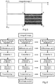
Fig. 4 shows an example of the positioning of a plurality of areas in a field of view of a camera; -
Fig. 5 shows an example of one of the plurality of areas in an integral image formed from the image shown inFig. 4 ; and -
Fig. 6 shows a detailed logic flow for the blockage detection algorithm utilized for detailed examples of the device, system and method for detecting windshield blockage of a vehicle. -
Fig. 1 shows an example of adevice 10 for detecting windshield blockage of a vehicle. Thedevice 10 comprises aninput unit 20, aprocessing unit 30 and anoutput unit 40. Theinput unit 20 is configured to provide theprocessing unit 30 with at least one initial image, the at least one initial image relating to a scene external to a vehicle viewed through a windshield of the vehicle. Theprocessing unit 30 is configured to transform each initial image of the at least one initial image into an integral image. Theprocessing unit 30 is configured also to calculate summed pixel values for each of a plurality of areas in the at least one integral image. Theprocessing unit 30 is configured to detect windshield blockage on the basis of at least one difference between the summed pixel values for at least a subset of the plurality of areas. Theoutput unit 40 is configured to output information that at least a part of the windshield has a blockage. - In an example, the at least one image was acquired by at least one camera that was not focussed on the windscreen of the vehicle.
- Thus in this manner, standard vehicle cameras that are viewing scenes external to the vehicle as part of navigation and/or safety systems, or as part of automatic driving systems can also be utilised to determine if a part or portion(s) of a vehicle's windscreen is blocked or partially blocked, where that part or portion is the portion of the windscreen associated with the field of view(s) of the camera(s) viewing the scene through the windscreen.
- According to an example, a value at a position x, y, in the integral image is calculated as the sum of all the pixels values above and to the left in the initial image including the pixel value at position x, y, in the initial image.
- According to an example, the plurality of areas each contain the same number of pixels.
- In an example, each area is 16x16 pixels in dimension.
- According to an example, the plurality of areas are situated along at least one line.
- In an example, the plurality of areas are situated along at least two lines that are angle one to the other.
- In an example, the plurality of areas are situated along at least three lines that are angled one to the other.
- In an example, the at least one line bisects the centre of the integral image.
- In an example, each of the at least one lines bisects the centre of the integral image.
- In an example, one of the at least one lines is a horizontal line and the at least three lines intersect in the centre of the horizontal line. In an example, the horizontal line can move up and down in the image from one image to the next. In other words, the three lines can intersect at the centre of a horizontal line that can move up and down whilst driving.
- In an example, one of the at least one lines is horizontally orientated in the at least one image.
- According to an example, the windshield blockage is detected on the basis of a plurality of differences between the summed pixel values for at least the subset of the plurality of areas.
- According to an example, the windshield blockage is detected on the basis of a plurality of differences between the summed pixels values for at least some of the adjacent pairs of the subset of the plurality of areas.
- According to an example, differences are calculated for all the available adjacent pairs of the subset of the plurality of areas.
- According to an example, the at least one line comprises a plurality of lines that are angled one to the other. At least one image segment is formed between at least parts of the plurality of lines. For a segment that is bounded on two sides by a part of one line and by a part of a second line, the at least one subset of the plurality of areas comprises the plurality of areas on the part of the first line and on the part of the second line.
- In an example, for each of the segments bounded by parts of lines, the processing unit is configured to similarly detect a windshield blockage for each of those segments on the basis of the differences between the summed pixel values for the plurality of areas on the parts of the lines that border each of those segments.
- According to an example, the at least one difference comprises a plurality of differences, and wherein the processing unit is configured to detect windshield blockage on the basis of a variation in at least a subset of the plurality of differences.
- In an example, the processing unit is configured to detect windshield blockage on the basis of a variation the plurality of differences.
- According to an example, detection of windshield blockage comprises utilisation of a training data set.
- In an example, the training data set comprises image data that exhibits windshield blockage. In an example, the training data set comprises image data that does not exhibit windshield blockage. This training data can be used to adjust the parameters of a classification algorithm, which decides based on the trained parameters if a new set of differences belongs to blocked/non-blocked regions.
- In an example, a plurality of cameras can be utilised to have different fields of view through a vehicle's windscreen, thereby covering more area of the windscreen.
-
Fig. 2 shows an example of asystem 100 for detecting windshield blockage for a vehicle. The system comprises at least onecamera 110 and adevice 10 for detecting windshield blockage of a vehicle as described above with respect to any of the examples ofFig. 1 . The at least onecamera 110 is configured to be located within avehicle 120 and the at least onecamera 110 is configured to acquire the at least one image relating to a scene external to thevehicle 120 viewed through awindshield 130 of the vehicle. The device is located on or within the vehicle. - In an example, the at least one
camera 110 is theinput unit 20. -
Fig. 3 shows amethod 200 for detecting windshield blockage of a vehicle in its basic steps. Themethod 200 comprises: - in a providing
step 210, also referred to as step a), providing a processing unit (30) with at least one initial image, the at least one initial image relating to a scene external to a vehicle viewed through a windshield of the vehicle; - in a transforming
step 220, also referred to as step b), transforming by the processing unit each initial image of the at least one initial image into an integral image; - in a calculating
step 230, also referred to as step c), calculating by the processing unit summed pixel values for each of a plurality of areas in the at least one integral image; - in a detecting
step 240, also referred to as step d), detecting by the processing unit windshield blockage on the basis of at least one difference between the summed pixel values for at least a subset of the plurality of areas; and - in an outputting
step 250, also referred to as step e), outputting with an output unit (40) output information that the at least a part of the windshield has a blockage. - In an example, a value at a position x, y, in the integral image is calculated as the sum of all the pixels values above and to the left in the initial image including the pixel value at position x, y, in the initial image.
- In an example, the plurality of areas each contain the same number of pixels.
- In an example, the plurality of areas are situated along at least one line.
- In an example, in step d) the windshield blockage is detected on the basis of a plurality of differences between the summed pixel values for at least the subset of the plurality of areas.
- In an example in step d) the windshield blockage is detected on the basis of a plurality of differences between the summed pixels values for at least some of the adjacent pairs of the subset of the plurality of areas.
- In an example, in step d) differences are calculated for all the available adjacent pairs of the subset of the plurality of areas.
- In an example, the at least one line comprises a plurality of lines that are angled one to the other, and wherein at least one image segment is formed between at least parts of the plurality of lines, and wherein for a segment that is bounded on two sides by a part of one line and by a part of a second line, the at least one subset of the plurality of areas comprises the plurality of areas on the part of the first line and on the part of the second line.
- In an example, the at least one difference comprises a plurality of differences, and wherein the processing unit is configured to detect windshield blockage on the basis of a variation in at least a subset of the plurality of differences.
- In an example, detection of windshield blockage comprises utilisation of a classifier.
- In an example, detection of windshield blockage comprises utilisation of a training data set.
- The device, system and method are now described in further detail with respect to
Figs. 4-6 . - The device, system and method described here enables the detection of detect blockage / partial blockage events occuring on the windscreen in front of the field of view of a camera-based driver assistance system. The design provides robustness of the blockage detection to external factors, such as illumination changes and partial obstructions. By utilizing the benefits of the image processing concept of the integral image, the present blockage detection algorithm reveals the strength of the spatial relationship of adiacent regions of the image. A weak spatial relationship between the regions can be used to indicate the presence of a blockage event, while a strong relationship between the regions can be used to indicate a clear field of view.
- Thus, as described above the algorithm uses the concept of the integral image. When a new (or initial) image I is processed by the detector, an integral image I' is first computed. When computing an integral image, a Summed Area Table (SAT) is created with the same size as the initial image I. The table is the integral image I'. In this table, at any point (x,y) the value is represented by the sum of all the pixel values above, to the left and including the original pixel value of (x,y) itself.
- The value in the SAT at (x,y) is simply calculated by:

- The SAT can be computed efficiently in a single pass over the image I, as the value in the SAT at (x,y) is

- The algorithm relies on the difference of sums of adjacent rectangles placed along 3 lines on the field of view of the camera. The rectangles for the ADAS blockage detector have a size of 16 by 16 pixels, but other dimensions can be used, depending on the application scenario. The rectangles are situated on 3 lines intersected at the center of the horizon line, as shown in
Fig. 4 . - Initially, the sum for all the 16 by 16 pixel blocks is computed by employing the integral image as discussed above. The windshield obstruction algorithm then computes the differences between sums of adjacent blocks of pixels and observes how much variation there is in a subset of differences.
-
Fig. 5 shows an area of 16 pixels in the integral image. Thus, once the above equation has been used to calculate and fill up the SAT, that is generate an integral image, the task of calculating the sum of pixels in any rectangle, which is a subset of the original image, is carried out. To compute the sum of a rectangle from the original image, 4 values from the SAT can be used. Only using only these 4 values, the sum S of the pixels within a region defined by 4 points, A(x,y), B(x,y), C(x,y) and D(x,y) is computed by using the following equation:
- Thus, although an integral image is calculated for the complete image, actually only integral image values need to be calculated for the rectangles shown in
Fig. 4 . - Returning to
Fig. 4 , the blocks of pixels (areas) are situated on 3 lines: one line is represented by the horizon line and the other two are symmetric to the first line, as observed inFig. 4 . The 3 lines form 6 segments, 2 from their intersection point to the left and right on the horizon line, 2 towards the top side and 2 towards the bottom side of the image. Thus one segment is bounded by part of one line of blocks of pixels at approx. 1 o' clock and by another part of one line of blocks at approx. 3 o' clock (30 degrees). A second segment is bounded by part of one line of blocks of pixels at approx. 3 o' clock and by another part of one line of blocks at approx. 4 o' clock (120 degrees). A third segment is bounded by part of one line of blocks of pixels at approx. 4 o' clock and by another part of one line of blocks at approx. 8 o' clock (240 degrees). A fourth segment is bounded by part of one line of blocks of pixels at approx. 8 o' clock and by another part of one line of blocks at approx. 9 o' clock (270 degrees). A fifth segment is bounded by part of one line of blocks of pixels at approx. 9 o' clock and by another part of one line of blocks at approx. 11 o' clock (330 degrees). And the sixth segment is bounded by part of one line of blocks of pixels at approx. 11 o' clock and by another part of one line of blocks at approx. 1 o' clock (30 degrees). The lines of blocks of pixels can be angled differently to that shown inFig. 4 , which is just an example. Also, there can be other numbers of lines of blocks of pixels (area) angled to one another as required, and as such there can be other numbers of segments bounded on both sides by blocks of pixels. - For each of the 6 segments, a set of differences between the sum of pixels between adjacent blocks is computed. If a segment has n blocks, n-1 differences will be generated. Thus, referring to the segment bounded by part of one line of segments at approx. 1 o' clock and by part of one line of segments at approx. 3 o' clock the n segments are those situated along both parts of those lines including the centre block of pixels. Thus the calculation of the differences between the summed values if adjacent blocks of pixels can be considered to start at one end of part of one line, progress to the centre pixel and then progress back out along the other part of the line that bounds a segment.
- Large or small values of the differences for each of the 6 segments are a measure of the strength of the spatial relationship between the different regions of the initial image. Six training sets are formed by extracting the 6 sets of values from positive and negative examples of camera blockage events from multiple images and 6 training sets. Using the training sets, a number of 6 "2-class" generic classifiers (e.g. logistic regression) are trained. After the training of the 2-class classifiers is conducted, when a new image is acquired by the camera and processed as discussed above, the 6 classifiers can be used to output a set of 6 probabilities between 0 and 1. The output from each of the 6 classifiers represents the likelihood of the corresponding region of the image being obstructed.
- Subsequently, for each line segment, a segment analyzer is used as a customizable algorithm to analyze the output of the 2-class classifiers. Each segment analyzer process a vector of outputs generated by one of the 2-class classifiers on a sequence of N frames. The segment analyzer performs a non-trainable mathematical operation, such as mean or median. The size of the vector N is variable and application specific. For a fast decision on a line segment, a small N can be chosen, while for an increased stability of the detector, a large value of N can be chosen.
- The output of the segment analyzers is integrated into a decision module. In the decision module, thresholding of the output of the segment analyzers with empirically determined thresholds takes place, for different areas of the image and for day/night driving. The thresholding operation outputs binary 0 or 1 values. If the segment analyzers corresponding to line segments below the horizon line produce values below the threshold, this indicates that there is a bottom partial blockage.
- As a vehicle (e.g. car) moves and a new frame is acquired, the 6 "2-class" classifiers produce their output and the corresponding segment analyzers update their vectors of probabilities. In this way, no abrupt changes occur in the output of the final detector, as only one of N components of the segment analyzers changes.
- The confidence of the detector is represented by the equation below:

-
Fig. 6 shows a detailed example of the logic flow of the blockage detection algorithm. The following steps are undertaken: - a) The image is received by the algorithm. An image can be seen as a matrix, with rows and columns.
- b) The integral image is computed, thus obtaining a new matrix.
- c) From the new matrix, the 6 sets of sums are computed.
- d) Then, the 6 sets of differences are computed
- e) The 6 sets of differences serve as input in the testing phase to a 2-class classifier. The classifier outputs a value between 0 and 1 representing the degree of confidence that a segment is part of a "blocked" region of the image (matrix).
- f) 6 segment analyzers process the output of the 2-class classifiers. Each segment analyzer process a vector of outputs generated by one of the 2-class classifiers on a sequence of N frames. The segment analyzer will typically perform a non-trainable mathematical operation, such as mean or median.
- g) In the decision module, thresholding of the output of the segment analyzers with empirically determined thresholds takes place.
- Here, more detail relating to the classification task is presented. The classification task is part of the pattern recognition or (machine learning) field. A 2-class classification algorithm has as output a set of 2 numbers, showing the "probability" of the input belonging to a class, and the other value is "1- the probability". The above described classification algorithm receives as input numbers (named features) and utilizes a "training" phase, during which it adjusts a set of parameters to best fit a separation hyperplane between the 2 classes. The testing phase uses a set of "training features", which are input values with known output value (class belonging). After fitting, the hyperplane is tuned according to the training examples. In the "testing" phase the classifier simply outputs the probability of the given input belonging to one of the 2 classes.
- The choice of the 2 class classification algorithm is application dependent: one could use naive Bayes classifier, or neural networks, or simple k-Nearest Neighbor. "Application dependent" here refers to hardware resources and desired level of accuracy, in other words to the specific application being considered.
- In another exemplary embodiment, a computer program or computer program element is provided that is characterized by being configured to execute the method steps of the method according to one of the preceding embodiments, on an appropriate system.
- The computer program element might therefore be stored on a computer unit, which might also be part of an embodiment. This computing unit may be configured to perform or induce performing of the steps of the method described above. Moreover, it may be configured to operate the components of the above described apparatus and/or system. The computing unit can be configured to operate automatically and/or to execute the orders of a user. A computer program may be loaded into a working memory of a data processor. The data processor may thus be equipped to carry out the method according to one of the preceding embodiments.
- According to a further exemplary embodiment of the present invention, a computer readable medium, such as a CD-ROM, is presented wherein the computer readable medium has a computer program element stored on it which computer program element is described by the preceding section.
- It has to be noted that embodiments of the invention are described with reference to different subject matters. In particular, some embodiments are described with reference to method type claims whereas other embodiments are described with reference to the device type claims. However, a person skilled in the art will gather from the above and the following description that, unless otherwise notified, in addition to any combination of features belonging to one type of subject matter also any combination between features relating to different subject matters is considered to be disclosed with this application. However, all features can be combined providing synergetic effects that are more than the simple summation of the features.
- While the invention has been illustrated and described in detail in the drawings and foregoing description, such illustration and description are to be considered illustrative or exemplary and not restrictive. The invention is not limited to the disclosed embodiments. Other variations to the disclosed embodiments can be understood and effected by those skilled in the art in practicing a claimed invention, from a study of the drawings, the disclosure, and the dependent claims.
- In the claims, the word "comprising" does not exclude other elements or steps, and the indefinite article "a" or "an" does not exclude a plurality. A single processor or other unit may fulfill the functions of several items re-cited in the claims. The mere fact that certain measures are re-cited in mutually different dependent claims does not indicate that a combination of these measures cannot be used to advantage. Any reference signs in the claims should not be construed as limiting the scope.
Claims (14)
- A device (10) for detecting windshield blockage of a vehicle, comprising:- an input unit (20);- a processing unit (30); and- an output unit (40);wherein, the input unit is configured to provide the processing unit with at least one initial image, the at least one initial image relating to a scene external to a vehicle viewed through a windshield of the vehicle;
wherein, the processing unit is configured to transform each initial image of the at least one initial image into an integral image;
wherein, the processing unit is configured to calculate summed pixel values for each of a plurality of areas in the at least one integral image;
wherein, the processing unit is configured to detect windshield blockage on the basis of at least one difference between the summed pixel values for at least a subset of the plurality of areas; and
wherein, the output unit is configured to output information that at least a part of the windshield has a blockage. - Device according to claim 1, wherein a value at a position x, y, in the integral image is calculated as the sum of all the pixels values above and to the left in the initial image including the pixel value at position x, y, in the initial image.
- Device according to any of claims 1-2, wherein the plurality of areas each contain the same number of pixels.
- Device according to any of claims 1-3, wherein the plurality of areas are situated along at least one line.
- Device according to claim 4, wherein the windshield blockage is detected on the basis of a plurality of differences between the summed pixel values for at least the subset of the plurality of areas.
- Device according to claim 5, wherein the windshield blockage is detected on the basis of a plurality of differences between the summed pixels values for at least some of the adjacent pairs of the subset of the plurality of areas.
- Device according to claim 6, wherein differences are calculated for all the available adjacent pairs of the subset of the plurality of areas.
- Device according to any of claims 4-7, wherein the at least one line comprises a plurality of lines that are angled one to the other, and wherein at least one image segment is formed between at least parts of the plurality of lines, and wherein for a segment that is bounded on two sides by a part of one line and by a part of a second line, the at least one subset of the plurality of areas comprises the plurality of areas on the part of the first line and on the part of the second line.
- Device according to any of claims 1-8, wherein the at least one difference comprises a plurality of differences, and wherein the processing unit is configured to detect windshield blockage on the basis of a variation in at least a subset of the plurality of differences.
- Device according to any of claims 1-9, detection of windshield blockage comprises utilisation of a training data set.
- A system (100) for detecting windshield blockage for a vehicle, comprising:- at least one camera (110);- a device (10) for detecting windshield blockage of a vehicle according to any of claims 1-10;wherein, the at least one camera is configured to be located within a vehicle (120) and the at least one camera is configured to acquire the at least one image relating to a scene external to the vehicle viewed through a windshield (130) of the vehicle; and
wherein, the device is located on or within the vehicle. - A method (200) for detecting windshield blockage of a vehicle, comprising:(a) providing (210) a processing unit (30) with at least one initial image, the at least one initial image relating to a scene external to a vehicle viewed through a windshield of the vehicle;(b) transforming (220) by the processing unit each initial image of the at least one initial image into an integral image;(c) calculating (230) by the processing unit summed pixel values for each of a plurality of areas in the at least one integral image;(d) detecting (240) by the processing unit windshield blockage on the basis of at least one difference between the summed pixel values for at least a subset of the plurality of areas; and(e) outputting (250) with an output unit (40) output information that the at least a part of the windshield has a blockage.
- A computer program element for controlling a device according to any one of claims 1 to 10 and/or a system according to claim 11, which when executed by a processor is configured to carry out the method of claim 12.
- A computer readable medium having stored the computer program element of claim 13.
Priority Applications (1)
| Application Number | Priority Date | Filing Date | Title |
|---|---|---|---|
| EP17465571.2A EP3483781B1 (en) | 2017-11-13 | 2017-11-13 | Device for detecting windshield blockage |
Applications Claiming Priority (1)
| Application Number | Priority Date | Filing Date | Title |
|---|---|---|---|
| EP17465571.2A EP3483781B1 (en) | 2017-11-13 | 2017-11-13 | Device for detecting windshield blockage |
Publications (2)
| Publication Number | Publication Date |
|---|---|
| EP3483781A1 true EP3483781A1 (en) | 2019-05-15 |
| EP3483781B1 EP3483781B1 (en) | 2021-10-06 |
Family
ID=60543490
Family Applications (1)
| Application Number | Title | Priority Date | Filing Date |
|---|---|---|---|
| EP17465571.2A Active EP3483781B1 (en) | 2017-11-13 | 2017-11-13 | Device for detecting windshield blockage |
Country Status (1)
| Country | Link |
|---|---|
| EP (1) | EP3483781B1 (en) |
Cited By (1)
| Publication number | Priority date | Publication date | Assignee | Title |
|---|---|---|---|---|
| WO2024051614A1 (en) * | 2022-09-06 | 2024-03-14 | 华为技术有限公司 | Driver assistance method and related apparatus |
Citations (3)
| Publication number | Priority date | Publication date | Assignee | Title |
|---|---|---|---|---|
| EP2879370A1 (en) * | 2012-07-27 | 2015-06-03 | Clarion Co., Ltd. | Vehicle-mounted image recognition device |
| US9319637B2 (en) | 2012-03-27 | 2016-04-19 | Magna Electronics Inc. | Vehicle vision system with lens pollution detection |
| EP3070928A1 (en) * | 2013-11-14 | 2016-09-21 | Clarion Co., Ltd. | Surrounding environment recognition device |
-
2017
- 2017-11-13 EP EP17465571.2A patent/EP3483781B1/en active Active
Patent Citations (3)
| Publication number | Priority date | Publication date | Assignee | Title |
|---|---|---|---|---|
| US9319637B2 (en) | 2012-03-27 | 2016-04-19 | Magna Electronics Inc. | Vehicle vision system with lens pollution detection |
| EP2879370A1 (en) * | 2012-07-27 | 2015-06-03 | Clarion Co., Ltd. | Vehicle-mounted image recognition device |
| EP3070928A1 (en) * | 2013-11-14 | 2016-09-21 | Clarion Co., Ltd. | Surrounding environment recognition device |
Non-Patent Citations (1)
| Title |
|---|
| ANONYMOUS: "Summed area table", 2 May 2016 (2016-05-02), XP055269859, Retrieved from the Internet <URL:https://en.wikipedia.org/wiki/Summed_area_table> [retrieved on 20160502] * |
Cited By (1)
| Publication number | Priority date | Publication date | Assignee | Title |
|---|---|---|---|---|
| WO2024051614A1 (en) * | 2022-09-06 | 2024-03-14 | 华为技术有限公司 | Driver assistance method and related apparatus |
Also Published As
| Publication number | Publication date |
|---|---|
| EP3483781B1 (en) | 2021-10-06 |
Similar Documents
| Publication | Publication Date | Title |
|---|---|---|
| US8050459B2 (en) | System and method for detecting pedestrians | |
| KR101569411B1 (en) | Pedestrian realization apparatus and method | |
| US7362885B2 (en) | Object tracking and eye state identification method | |
| EP1806697B1 (en) | Segmenting image elements | |
| Kim et al. | Feature point classification based global motion estimation for video stabilization | |
| CN109034136B (en) | Image processing method, image processing apparatus, image capturing device, and storage medium | |
| EP3726421A2 (en) | Recognition method and apparatus for false detection of an abandoned object and image processing device | |
| US20090202145A1 (en) | Learning appartus, learning method, recognition apparatus, recognition method, and program | |
| US9619699B2 (en) | System and method for enhancing human counting by fusing results of human detection modalities | |
| CN107292303B (en) | Method and apparatus for license plate detection by means of edge-type sliding concentric windows | |
| US20130322754A1 (en) | Apparatus and method for extracting target, and recording medium storing program for performing the method | |
| Kim | Realtime lane tracking of curved local road | |
| KR20190047243A (en) | Apparatus and method for warning contamination of camera lens | |
| US20170109892A1 (en) | Method and apparatus for detecting a traffic state and electronic equipment | |
| US10489916B2 (en) | Method and apparatus for updating a background model | |
| US9911197B1 (en) | Moving object spotting by forward-backward motion history accumulation | |
| EP3224764B1 (en) | Systems and methods for object detection | |
| US9489737B2 (en) | Object detection apparatus and method | |
| US10402696B2 (en) | Scene obstruction detection using high pass filters | |
| US20180205877A1 (en) | Information processing apparatus, information processing method, system, and non-transitory computer-readable storage medium | |
| KR101441107B1 (en) | Method and apparatus for determining abnormal behavior | |
| US7813530B2 (en) | Motion detecting method and apparatus | |
| US10115028B2 (en) | Method and device for classifying an object in an image | |
| EP3483781B1 (en) | Device for detecting windshield blockage | |
| US20050129274A1 (en) | Motion-based segmentor detecting vehicle occupants using optical flow method to remove effects of illumination |
Legal Events
| Date | Code | Title | Description |
|---|---|---|---|
| PUAI | Public reference made under article 153(3) epc to a published international application that has entered the european phase |
Free format text: ORIGINAL CODE: 0009012 |
|
| STAA | Information on the status of an ep patent application or granted ep patent |
Free format text: STATUS: THE APPLICATION HAS BEEN PUBLISHED |
|
| AK | Designated contracting states |
Kind code of ref document: A1 Designated state(s): AL AT BE BG CH CY CZ DE DK EE ES FI FR GB GR HR HU IE IS IT LI LT LU LV MC MK MT NL NO PL PT RO RS SE SI SK SM TR |
|
| AX | Request for extension of the european patent |
Extension state: BA ME |
|
| STAA | Information on the status of an ep patent application or granted ep patent |
Free format text: STATUS: REQUEST FOR EXAMINATION WAS MADE |
|
| 17P | Request for examination filed |
Effective date: 20191115 |
|
| RBV | Designated contracting states (corrected) |
Designated state(s): AL AT BE BG CH CY CZ DE DK EE ES FI FR GB GR HR HU IE IS IT LI LT LU LV MC MK MT NL NO PL PT RO RS SE SI SK SM TR |
|
| GRAP | Despatch of communication of intention to grant a patent |
Free format text: ORIGINAL CODE: EPIDOSNIGR1 |
|
| STAA | Information on the status of an ep patent application or granted ep patent |
Free format text: STATUS: GRANT OF PATENT IS INTENDED |
|
| INTG | Intention to grant announced |
Effective date: 20210601 |
|
| GRAS | Grant fee paid |
Free format text: ORIGINAL CODE: EPIDOSNIGR3 |
|
| GRAA | (expected) grant |
Free format text: ORIGINAL CODE: 0009210 |
|
| STAA | Information on the status of an ep patent application or granted ep patent |
Free format text: STATUS: THE PATENT HAS BEEN GRANTED |
|
| AK | Designated contracting states |
Kind code of ref document: B1 Designated state(s): AL AT BE BG CH CY CZ DE DK EE ES FI FR GB GR HR HU IE IS IT LI LT LU LV MC MK MT NL NO PL PT RO RS SE SI SK SM TR |
|
| REG | Reference to a national code |
Ref country code: GB Ref legal event code: FG4D |
|
| REG | Reference to a national code |
Ref country code: CH Ref legal event code: EP Ref country code: AT Ref legal event code: REF Ref document number: 1436868 Country of ref document: AT Kind code of ref document: T Effective date: 20211015 |
|
| REG | Reference to a national code |
Ref country code: IE Ref legal event code: FG4D |
|
| REG | Reference to a national code |
Ref country code: DE Ref legal event code: R096 Ref document number: 602017047091 Country of ref document: DE |
|
| REG | Reference to a national code |
Ref country code: DE Ref legal event code: R079 Ref document number: 602017047091 Country of ref document: DE Free format text: PREVIOUS MAIN CLASS: G06K0009000000 Ipc: G06V0010000000 |
|
| REG | Reference to a national code |
Ref country code: LT Ref legal event code: MG9D |
|
| REG | Reference to a national code |
Ref country code: NL Ref legal event code: MP Effective date: 20211006 |
|
| REG | Reference to a national code |
Ref country code: AT Ref legal event code: MK05 Ref document number: 1436868 Country of ref document: AT Kind code of ref document: T Effective date: 20211006 |
|
| PG25 | Lapsed in a contracting state [announced via postgrant information from national office to epo] |
Ref country code: RS Free format text: LAPSE BECAUSE OF FAILURE TO SUBMIT A TRANSLATION OF THE DESCRIPTION OR TO PAY THE FEE WITHIN THE PRESCRIBED TIME-LIMIT Effective date: 20211006 Ref country code: LT Free format text: LAPSE BECAUSE OF FAILURE TO SUBMIT A TRANSLATION OF THE DESCRIPTION OR TO PAY THE FEE WITHIN THE PRESCRIBED TIME-LIMIT Effective date: 20211006 Ref country code: FI Free format text: LAPSE BECAUSE OF FAILURE TO SUBMIT A TRANSLATION OF THE DESCRIPTION OR TO PAY THE FEE WITHIN THE PRESCRIBED TIME-LIMIT Effective date: 20211006 Ref country code: BG Free format text: LAPSE BECAUSE OF FAILURE TO SUBMIT A TRANSLATION OF THE DESCRIPTION OR TO PAY THE FEE WITHIN THE PRESCRIBED TIME-LIMIT Effective date: 20220106 Ref country code: AT Free format text: LAPSE BECAUSE OF FAILURE TO SUBMIT A TRANSLATION OF THE DESCRIPTION OR TO PAY THE FEE WITHIN THE PRESCRIBED TIME-LIMIT Effective date: 20211006 |
|
| PG25 | Lapsed in a contracting state [announced via postgrant information from national office to epo] |
Ref country code: IS Free format text: LAPSE BECAUSE OF FAILURE TO SUBMIT A TRANSLATION OF THE DESCRIPTION OR TO PAY THE FEE WITHIN THE PRESCRIBED TIME-LIMIT Effective date: 20220206 Ref country code: SE Free format text: LAPSE BECAUSE OF FAILURE TO SUBMIT A TRANSLATION OF THE DESCRIPTION OR TO PAY THE FEE WITHIN THE PRESCRIBED TIME-LIMIT Effective date: 20211006 Ref country code: PT Free format text: LAPSE BECAUSE OF FAILURE TO SUBMIT A TRANSLATION OF THE DESCRIPTION OR TO PAY THE FEE WITHIN THE PRESCRIBED TIME-LIMIT Effective date: 20220207 Ref country code: PL Free format text: LAPSE BECAUSE OF FAILURE TO SUBMIT A TRANSLATION OF THE DESCRIPTION OR TO PAY THE FEE WITHIN THE PRESCRIBED TIME-LIMIT Effective date: 20211006 Ref country code: NO Free format text: LAPSE BECAUSE OF FAILURE TO SUBMIT A TRANSLATION OF THE DESCRIPTION OR TO PAY THE FEE WITHIN THE PRESCRIBED TIME-LIMIT Effective date: 20220106 Ref country code: NL Free format text: LAPSE BECAUSE OF FAILURE TO SUBMIT A TRANSLATION OF THE DESCRIPTION OR TO PAY THE FEE WITHIN THE PRESCRIBED TIME-LIMIT Effective date: 20211006 Ref country code: LV Free format text: LAPSE BECAUSE OF FAILURE TO SUBMIT A TRANSLATION OF THE DESCRIPTION OR TO PAY THE FEE WITHIN THE PRESCRIBED TIME-LIMIT Effective date: 20211006 Ref country code: HR Free format text: LAPSE BECAUSE OF FAILURE TO SUBMIT A TRANSLATION OF THE DESCRIPTION OR TO PAY THE FEE WITHIN THE PRESCRIBED TIME-LIMIT Effective date: 20211006 Ref country code: GR Free format text: LAPSE BECAUSE OF FAILURE TO SUBMIT A TRANSLATION OF THE DESCRIPTION OR TO PAY THE FEE WITHIN THE PRESCRIBED TIME-LIMIT Effective date: 20220107 Ref country code: ES Free format text: LAPSE BECAUSE OF FAILURE TO SUBMIT A TRANSLATION OF THE DESCRIPTION OR TO PAY THE FEE WITHIN THE PRESCRIBED TIME-LIMIT Effective date: 20211006 |
|
| REG | Reference to a national code |
Ref country code: CH Ref legal event code: PL |
|
| REG | Reference to a national code |
Ref country code: DE Ref legal event code: R097 Ref document number: 602017047091 Country of ref document: DE |
|
| REG | Reference to a national code |
Ref country code: DE Ref legal event code: R081 Ref document number: 602017047091 Country of ref document: DE Owner name: CONTINENTAL AUTONOMOUS MOBILITY GERMANY GMBH, DE Free format text: FORMER OWNER: CONTINENTAL AUTOMOTIVE GMBH, 30165 HANNOVER, DE Ref country code: DE Ref legal event code: R081 Ref document number: 602017047091 Country of ref document: DE Owner name: AUMOVIO AUTONOMOUS MOBILITY GERMANY GMBH, DE Free format text: FORMER OWNER: CONTINENTAL AUTOMOTIVE GMBH, 30165 HANNOVER, DE |
|
| PG25 | Lapsed in a contracting state [announced via postgrant information from national office to epo] |
Ref country code: SM Free format text: LAPSE BECAUSE OF FAILURE TO SUBMIT A TRANSLATION OF THE DESCRIPTION OR TO PAY THE FEE WITHIN THE PRESCRIBED TIME-LIMIT Effective date: 20211006 Ref country code: SK Free format text: LAPSE BECAUSE OF FAILURE TO SUBMIT A TRANSLATION OF THE DESCRIPTION OR TO PAY THE FEE WITHIN THE PRESCRIBED TIME-LIMIT Effective date: 20211006 Ref country code: RO Free format text: LAPSE BECAUSE OF FAILURE TO SUBMIT A TRANSLATION OF THE DESCRIPTION OR TO PAY THE FEE WITHIN THE PRESCRIBED TIME-LIMIT Effective date: 20211006 Ref country code: MC Free format text: LAPSE BECAUSE OF FAILURE TO SUBMIT A TRANSLATION OF THE DESCRIPTION OR TO PAY THE FEE WITHIN THE PRESCRIBED TIME-LIMIT Effective date: 20211006 Ref country code: LU Free format text: LAPSE BECAUSE OF NON-PAYMENT OF DUE FEES Effective date: 20211113 Ref country code: EE Free format text: LAPSE BECAUSE OF FAILURE TO SUBMIT A TRANSLATION OF THE DESCRIPTION OR TO PAY THE FEE WITHIN THE PRESCRIBED TIME-LIMIT Effective date: 20211006 Ref country code: DK Free format text: LAPSE BECAUSE OF FAILURE TO SUBMIT A TRANSLATION OF THE DESCRIPTION OR TO PAY THE FEE WITHIN THE PRESCRIBED TIME-LIMIT Effective date: 20211006 Ref country code: CZ Free format text: LAPSE BECAUSE OF FAILURE TO SUBMIT A TRANSLATION OF THE DESCRIPTION OR TO PAY THE FEE WITHIN THE PRESCRIBED TIME-LIMIT Effective date: 20211006 Ref country code: BE Free format text: LAPSE BECAUSE OF NON-PAYMENT OF DUE FEES Effective date: 20211130 |
|
| REG | Reference to a national code |
Ref country code: BE Ref legal event code: MM Effective date: 20211130 |
|
| PLBE | No opposition filed within time limit |
Free format text: ORIGINAL CODE: 0009261 |
|
| STAA | Information on the status of an ep patent application or granted ep patent |
Free format text: STATUS: NO OPPOSITION FILED WITHIN TIME LIMIT |
|
| PG25 | Lapsed in a contracting state [announced via postgrant information from national office to epo] |
Ref country code: LI Free format text: LAPSE BECAUSE OF NON-PAYMENT OF DUE FEES Effective date: 20211130 Ref country code: CH Free format text: LAPSE BECAUSE OF NON-PAYMENT OF DUE FEES Effective date: 20211130 |
|
| 26N | No opposition filed |
Effective date: 20220707 |
|
| GBPC | Gb: european patent ceased through non-payment of renewal fee |
Effective date: 20220106 |
|
| PG25 | Lapsed in a contracting state [announced via postgrant information from national office to epo] |
Ref country code: IE Free format text: LAPSE BECAUSE OF NON-PAYMENT OF DUE FEES Effective date: 20211113 Ref country code: GB Free format text: LAPSE BECAUSE OF NON-PAYMENT OF DUE FEES Effective date: 20220106 Ref country code: AL Free format text: LAPSE BECAUSE OF FAILURE TO SUBMIT A TRANSLATION OF THE DESCRIPTION OR TO PAY THE FEE WITHIN THE PRESCRIBED TIME-LIMIT Effective date: 20211006 |
|
| PG25 | Lapsed in a contracting state [announced via postgrant information from national office to epo] |
Ref country code: SI Free format text: LAPSE BECAUSE OF FAILURE TO SUBMIT A TRANSLATION OF THE DESCRIPTION OR TO PAY THE FEE WITHIN THE PRESCRIBED TIME-LIMIT Effective date: 20211006 Ref country code: FR Free format text: LAPSE BECAUSE OF NON-PAYMENT OF DUE FEES Effective date: 20211206 |
|
| PG25 | Lapsed in a contracting state [announced via postgrant information from national office to epo] |
Ref country code: IT Free format text: LAPSE BECAUSE OF FAILURE TO SUBMIT A TRANSLATION OF THE DESCRIPTION OR TO PAY THE FEE WITHIN THE PRESCRIBED TIME-LIMIT Effective date: 20211006 |
|
| PG25 | Lapsed in a contracting state [announced via postgrant information from national office to epo] |
Ref country code: CY Free format text: LAPSE BECAUSE OF FAILURE TO SUBMIT A TRANSLATION OF THE DESCRIPTION OR TO PAY THE FEE WITHIN THE PRESCRIBED TIME-LIMIT Effective date: 20211006 |
|
| PG25 | Lapsed in a contracting state [announced via postgrant information from national office to epo] |
Ref country code: HU Free format text: LAPSE BECAUSE OF FAILURE TO SUBMIT A TRANSLATION OF THE DESCRIPTION OR TO PAY THE FEE WITHIN THE PRESCRIBED TIME-LIMIT; INVALID AB INITIO Effective date: 20171113 |
|
| PG25 | Lapsed in a contracting state [announced via postgrant information from national office to epo] |
Ref country code: MK Free format text: LAPSE BECAUSE OF FAILURE TO SUBMIT A TRANSLATION OF THE DESCRIPTION OR TO PAY THE FEE WITHIN THE PRESCRIBED TIME-LIMIT Effective date: 20211006 |
|
| PG25 | Lapsed in a contracting state [announced via postgrant information from national office to epo] |
Ref country code: TR Free format text: LAPSE BECAUSE OF FAILURE TO SUBMIT A TRANSLATION OF THE DESCRIPTION OR TO PAY THE FEE WITHIN THE PRESCRIBED TIME-LIMIT Effective date: 20211006 |
|
| PG25 | Lapsed in a contracting state [announced via postgrant information from national office to epo] |
Ref country code: MT Free format text: LAPSE BECAUSE OF FAILURE TO SUBMIT A TRANSLATION OF THE DESCRIPTION OR TO PAY THE FEE WITHIN THE PRESCRIBED TIME-LIMIT Effective date: 20211006 |
|
| REG | Reference to a national code |
Ref country code: DE Ref legal event code: R081 Ref document number: 602017047091 Country of ref document: DE Owner name: AUMOVIO AUTONOMOUS MOBILITY GERMANY GMBH, DE Free format text: FORMER OWNER: CONTINENTAL AUTONOMOUS MOBILITY GERMANY GMBH, 85057 INGOLSTADT, DE |
|
| PGFP | Annual fee paid to national office [announced via postgrant information from national office to epo] |
Ref country code: DE Payment date: 20251130 Year of fee payment: 9 |