EP3483528A1 - Refrigeration cycle system - Google Patents
Refrigeration cycle system Download PDFInfo
- Publication number
- EP3483528A1 EP3483528A1 EP16908152.8A EP16908152A EP3483528A1 EP 3483528 A1 EP3483528 A1 EP 3483528A1 EP 16908152 A EP16908152 A EP 16908152A EP 3483528 A1 EP3483528 A1 EP 3483528A1
- Authority
- EP
- European Patent Office
- Prior art keywords
- controller
- heat exchanger
- refrigeration cycle
- satisfied
- start condition
- Prior art date
- Legal status (The legal status is an assumption and is not a legal conclusion. Google has not performed a legal analysis and makes no representation as to the accuracy of the status listed.)
- Granted
Links
Images





Classifications
-
- F—MECHANICAL ENGINEERING; LIGHTING; HEATING; WEAPONS; BLASTING
- F25—REFRIGERATION OR COOLING; COMBINED HEATING AND REFRIGERATION SYSTEMS; HEAT PUMP SYSTEMS; MANUFACTURE OR STORAGE OF ICE; LIQUEFACTION SOLIDIFICATION OF GASES
- F25B—REFRIGERATION MACHINES, PLANTS OR SYSTEMS; COMBINED HEATING AND REFRIGERATION SYSTEMS; HEAT PUMP SYSTEMS
- F25B47/00—Arrangements for preventing or removing deposits or corrosion, not provided for in another subclass
- F25B47/02—Defrosting cycles
-
- F—MECHANICAL ENGINEERING; LIGHTING; HEATING; WEAPONS; BLASTING
- F25—REFRIGERATION OR COOLING; COMBINED HEATING AND REFRIGERATION SYSTEMS; HEAT PUMP SYSTEMS; MANUFACTURE OR STORAGE OF ICE; LIQUEFACTION SOLIDIFICATION OF GASES
- F25B—REFRIGERATION MACHINES, PLANTS OR SYSTEMS; COMBINED HEATING AND REFRIGERATION SYSTEMS; HEAT PUMP SYSTEMS
- F25B13/00—Compression machines, plants or systems, with reversible cycle
-
- F—MECHANICAL ENGINEERING; LIGHTING; HEATING; WEAPONS; BLASTING
- F25—REFRIGERATION OR COOLING; COMBINED HEATING AND REFRIGERATION SYSTEMS; HEAT PUMP SYSTEMS; MANUFACTURE OR STORAGE OF ICE; LIQUEFACTION SOLIDIFICATION OF GASES
- F25B—REFRIGERATION MACHINES, PLANTS OR SYSTEMS; COMBINED HEATING AND REFRIGERATION SYSTEMS; HEAT PUMP SYSTEMS
- F25B47/00—Arrangements for preventing or removing deposits or corrosion, not provided for in another subclass
- F25B47/02—Defrosting cycles
- F25B47/022—Defrosting cycles hot gas defrosting
-
- F—MECHANICAL ENGINEERING; LIGHTING; HEATING; WEAPONS; BLASTING
- F25—REFRIGERATION OR COOLING; COMBINED HEATING AND REFRIGERATION SYSTEMS; HEAT PUMP SYSTEMS; MANUFACTURE OR STORAGE OF ICE; LIQUEFACTION SOLIDIFICATION OF GASES
- F25B—REFRIGERATION MACHINES, PLANTS OR SYSTEMS; COMBINED HEATING AND REFRIGERATION SYSTEMS; HEAT PUMP SYSTEMS
- F25B47/00—Arrangements for preventing or removing deposits or corrosion, not provided for in another subclass
- F25B47/02—Defrosting cycles
- F25B47/022—Defrosting cycles hot gas defrosting
- F25B47/025—Defrosting cycles hot gas defrosting by reversing the cycle
-
- F—MECHANICAL ENGINEERING; LIGHTING; HEATING; WEAPONS; BLASTING
- F25—REFRIGERATION OR COOLING; COMBINED HEATING AND REFRIGERATION SYSTEMS; HEAT PUMP SYSTEMS; MANUFACTURE OR STORAGE OF ICE; LIQUEFACTION SOLIDIFICATION OF GASES
- F25D—REFRIGERATORS; COLD ROOMS; ICE-BOXES; COOLING OR FREEZING APPARATUS NOT OTHERWISE PROVIDED FOR
- F25D21/00—Defrosting; Preventing frosting; Removing condensed or defrost water
- F25D21/06—Removing frost
-
- F—MECHANICAL ENGINEERING; LIGHTING; HEATING; WEAPONS; BLASTING
- F25—REFRIGERATION OR COOLING; COMBINED HEATING AND REFRIGERATION SYSTEMS; HEAT PUMP SYSTEMS; MANUFACTURE OR STORAGE OF ICE; LIQUEFACTION SOLIDIFICATION OF GASES
- F25B—REFRIGERATION MACHINES, PLANTS OR SYSTEMS; COMBINED HEATING AND REFRIGERATION SYSTEMS; HEAT PUMP SYSTEMS
- F25B2313/00—Compression machines, plants or systems with reversible cycle not otherwise provided for
- F25B2313/008—Refrigerant heaters
-
- F—MECHANICAL ENGINEERING; LIGHTING; HEATING; WEAPONS; BLASTING
- F25—REFRIGERATION OR COOLING; COMBINED HEATING AND REFRIGERATION SYSTEMS; HEAT PUMP SYSTEMS; MANUFACTURE OR STORAGE OF ICE; LIQUEFACTION SOLIDIFICATION OF GASES
- F25B—REFRIGERATION MACHINES, PLANTS OR SYSTEMS; COMBINED HEATING AND REFRIGERATION SYSTEMS; HEAT PUMP SYSTEMS
- F25B2313/00—Compression machines, plants or systems with reversible cycle not otherwise provided for
- F25B2313/029—Control issues
- F25B2313/0293—Control issues related to the indoor fan, e.g. controlling speed
-
- F—MECHANICAL ENGINEERING; LIGHTING; HEATING; WEAPONS; BLASTING
- F25—REFRIGERATION OR COOLING; COMBINED HEATING AND REFRIGERATION SYSTEMS; HEAT PUMP SYSTEMS; MANUFACTURE OR STORAGE OF ICE; LIQUEFACTION SOLIDIFICATION OF GASES
- F25B—REFRIGERATION MACHINES, PLANTS OR SYSTEMS; COMBINED HEATING AND REFRIGERATION SYSTEMS; HEAT PUMP SYSTEMS
- F25B2313/00—Compression machines, plants or systems with reversible cycle not otherwise provided for
- F25B2313/029—Control issues
- F25B2313/0294—Control issues related to the outdoor fan, e.g. controlling speed
-
- F—MECHANICAL ENGINEERING; LIGHTING; HEATING; WEAPONS; BLASTING
- F25—REFRIGERATION OR COOLING; COMBINED HEATING AND REFRIGERATION SYSTEMS; HEAT PUMP SYSTEMS; MANUFACTURE OR STORAGE OF ICE; LIQUEFACTION SOLIDIFICATION OF GASES
- F25B—REFRIGERATION MACHINES, PLANTS OR SYSTEMS; COMBINED HEATING AND REFRIGERATION SYSTEMS; HEAT PUMP SYSTEMS
- F25B2313/00—Compression machines, plants or systems with reversible cycle not otherwise provided for
- F25B2313/031—Sensor arrangements
- F25B2313/0314—Temperature sensors near the indoor heat exchanger
-
- F—MECHANICAL ENGINEERING; LIGHTING; HEATING; WEAPONS; BLASTING
- F25—REFRIGERATION OR COOLING; COMBINED HEATING AND REFRIGERATION SYSTEMS; HEAT PUMP SYSTEMS; MANUFACTURE OR STORAGE OF ICE; LIQUEFACTION SOLIDIFICATION OF GASES
- F25B—REFRIGERATION MACHINES, PLANTS OR SYSTEMS; COMBINED HEATING AND REFRIGERATION SYSTEMS; HEAT PUMP SYSTEMS
- F25B2400/00—Component parts or details not otherwise provided for in this subclass
- F25B2400/01—Heaters
-
- F—MECHANICAL ENGINEERING; LIGHTING; HEATING; WEAPONS; BLASTING
- F25—REFRIGERATION OR COOLING; COMBINED HEATING AND REFRIGERATION SYSTEMS; HEAT PUMP SYSTEMS; MANUFACTURE OR STORAGE OF ICE; LIQUEFACTION SOLIDIFICATION OF GASES
- F25B—REFRIGERATION MACHINES, PLANTS OR SYSTEMS; COMBINED HEATING AND REFRIGERATION SYSTEMS; HEAT PUMP SYSTEMS
- F25B2600/00—Control issues
- F25B2600/11—Fan speed control
- F25B2600/112—Fan speed control of evaporator fans
-
- F—MECHANICAL ENGINEERING; LIGHTING; HEATING; WEAPONS; BLASTING
- F25—REFRIGERATION OR COOLING; COMBINED HEATING AND REFRIGERATION SYSTEMS; HEAT PUMP SYSTEMS; MANUFACTURE OR STORAGE OF ICE; LIQUEFACTION SOLIDIFICATION OF GASES
- F25B—REFRIGERATION MACHINES, PLANTS OR SYSTEMS; COMBINED HEATING AND REFRIGERATION SYSTEMS; HEAT PUMP SYSTEMS
- F25B2700/00—Sensing or detecting of parameters; Sensors therefor
- F25B2700/21—Temperatures
- F25B2700/2117—Temperatures of an evaporator
- F25B2700/21171—Temperatures of an evaporator of the fluid cooled by the evaporator
- F25B2700/21172—Temperatures of an evaporator of the fluid cooled by the evaporator at the inlet
-
- F—MECHANICAL ENGINEERING; LIGHTING; HEATING; WEAPONS; BLASTING
- F25—REFRIGERATION OR COOLING; COMBINED HEATING AND REFRIGERATION SYSTEMS; HEAT PUMP SYSTEMS; MANUFACTURE OR STORAGE OF ICE; LIQUEFACTION SOLIDIFICATION OF GASES
- F25B—REFRIGERATION MACHINES, PLANTS OR SYSTEMS; COMBINED HEATING AND REFRIGERATION SYSTEMS; HEAT PUMP SYSTEMS
- F25B2700/00—Sensing or detecting of parameters; Sensors therefor
- F25B2700/21—Temperatures
- F25B2700/2117—Temperatures of an evaporator
- F25B2700/21175—Temperatures of an evaporator of the refrigerant at the outlet of the evaporator
-
- Y—GENERAL TAGGING OF NEW TECHNOLOGICAL DEVELOPMENTS; GENERAL TAGGING OF CROSS-SECTIONAL TECHNOLOGIES SPANNING OVER SEVERAL SECTIONS OF THE IPC; TECHNICAL SUBJECTS COVERED BY FORMER USPC CROSS-REFERENCE ART COLLECTIONS [XRACs] AND DIGESTS
- Y02—TECHNOLOGIES OR APPLICATIONS FOR MITIGATION OR ADAPTATION AGAINST CLIMATE CHANGE
- Y02B—CLIMATE CHANGE MITIGATION TECHNOLOGIES RELATED TO BUILDINGS, e.g. HOUSING, HOUSE APPLIANCES OR RELATED END-USER APPLICATIONS
- Y02B30/00—Energy efficient heating, ventilation or air conditioning [HVAC]
- Y02B30/70—Efficient control or regulation technologies, e.g. for control of refrigerant flow, motor or heating
Definitions
- the present invention relates to a refrigeration cycle apparatus configured to perform defrosting operation.
- a refrigeration cycle apparatus configured to perform defrosting operation (defrost) for melting and removing frost formed on an evaporator has been conventionally known.
- defrosting operation defrost
- Japanese Patent Laying-Open No. 5-34049 discloses a refrigeration apparatus for a container configured to perform defrosting operation. According to the refrigeration apparatus for a container, switching between heating defrost and off-cycle defrost can be performed based on a prescribed condition, thereby reducing the consumed power required for the defrosting operation.
- Both liquid refrigerant and gas refrigerant exist in an evaporator.
- an amount of the liquid refrigerant in the evaporator is large at the start of the defrosting operation, an amount of heat used to vaporize the liquid refrigerant, of an amount of heat generated to melt frost, is large, and thus, an amount of heat used to melt frost is reduced.
- the length of time required for the defrosting operation corresponds to the interruption time of normal operation, and thus, it is desirable that the length of time required for the defrosting operation should be short.
- Japanese Patent Laying-Open No. 5-34049 (PTL 1) does not disclose a configuration for shortening the length of time required for the defrosting operation.
- the present invention has been made to solve the above-described problem, and an object of the present invention is to shorten a length of time required for defrosting operation.
- a refrigeration cycle apparatus is configured to circulate refrigerant in a first circulation direction in order of a first heat exchanger, a compressor, a second heat exchanger, and an expansion valve, and perform defrosting operation when a start condition for the defrosting operation is satisfied.
- the refrigeration cycle apparatus includes: a first blower; and a controller.
- the first blower is configured to blow air into the first heat exchanger.
- the controller is configured to control an amount of air blown by the first blower.
- the controller is configured to increase the amount of air blown by the first blower per unit time, when the start condition is satisfied.
- the amount of air blown by the first blower per unit time is larger after the start condition for the defrosting operation is satisfied than before the start condition is satisfied. Therefore, the heat exchange efficiency of an evaporator after the start condition for the defrosting operation is satisfied is increased and vaporization of liquid refrigerant is promoted. Since the defrosting operation is performed with an amount of the liquid refrigerant in the evaporator being small, an amount of heat used to melt frost, of an amount of heat used for defrosting, is large. As a result, the length of time required for the defrosting operation, i.e., the interruption time of normal operation, can be shortened and the user's comfort can be increased.
- Fig. 1 is a functional block diagram showing a configuration of a refrigerator 1 which is one example of a refrigeration cycle apparatus according to a first embodiment.
- refrigerator 1 includes an outdoor unit 11 and an indoor unit 21.
- Outdoor unit 11 includes a compressor 102, a condenser 103, an outdoor fan 112, and a controller 31.
- Indoor unit 21 includes an evaporator 101, an expansion valve 104, an indoor fan 111, an indoor heater 121, and temperature sensors 41 and 42.
- Controller 31 may be included in indoor unit 21, or may be arranged outside outdoor unit 11 and indoor unit 21.
- refrigerant circulates through evaporator 101, compressor 102, condenser 103, and expansion valve 104 in this order.
- Compressor 102 compresses low-pressure gas refrigerant received from evaporator 101, and outputs high-pressure gas refrigerant to condenser 103.
- Condenser 103 receives and condenses the high-temperature and high-pressure gas refrigerant from compressor 102, and discharges liquid refrigerant to expansion valve 104. Heat (condensation heat) generated when the gas refrigerant condenses to the liquid refrigerant is released from condenser 103.
- Outdoor fan 112 blows air into condenser 103.
- Expansion valve 104 adiabatically expands and decompresses the liquid refrigerant from condenser 103, and discharges wet vapor to evaporator 101.
- a linear expansion valve (LEV) can, for example, be used as expansion valve 104.
- Evaporator 101 receives the wet vapor from expansion valve 104, evaporates the liquid refrigerant included in the wet vapor, and discharges gas refrigerant to compressor 102. In evaporator 101, the liquid refrigerant deprives the indoor air of heat (vaporization heat) and evaporates.
- Indoor fan 111 blows air into evaporator 101.
- Indoor heater 121 operates during defrosting operation to heat evaporator 101.
- Temperature sensor 41 is disposed in a pipe of evaporator 101 and outputs the detected pipe temperature to controller 31.
- Temperature sensor 42 is disposed near an air inlet of evaporator 101 and outputs the detected air temperature to controller 31.
- Controller 31 controls a driving frequency of compressor 102 to thereby control an amount of the refrigerant discharged by compressor 102 per unit time. Controller 31 obtains the pipe temperature of evaporator 101 from temperature sensor 41. Controller 31 obtains the temperature of the air taken into evaporator 101 from temperature sensor 42. Controller 31 adjusts a rotation speed of each of indoor fan 111 and outdoor fan 112 to thereby control an amount of air blown by each of indoor fan 111 and outdoor fan 112 per unit time. Controller 31 has a control unit (not shown) including a processor such as, for example, a CPU (Central Processing Unit). The controller has a storage unit (not shown) including a nonvolatile memory such as, for example, a flash memory. The storage unit can store, for example, an OS (Operating System) read and executed by the control unit, programs for various applications (e.g., a program for controlling the defrosting operation), and various types of data used by the programs.
- OS Operating System
- frost may in some cases form on evaporator 101 arranged in indoor unit 21 having a low room temperature. Defrosting in the first embodiment is performed by stopping compressor 102 and heating evaporator 101 by indoor heater 121.
- Fig. 2 is a flowchart for illustrating one example of a process flow of defrosting operation performed in a general refrigeration cycle apparatus. The process shown in Fig. 2 is executed at certain time intervals by a not-shown main routine. Hereinafter, a step will be simply indicated as "S".
- the controller determines whether or not a defrosting start condition is satisfied.
- the defrosting start condition may be any condition as long as it is a condition indicating that the heat exchange efficiency of the evaporator falls below a reference value.
- Examples of the defrosting start condition can include a condition that a difference between the air temperature near the inlet of evaporator 101 and an evaporation temperature is greater than a prescribed value.
- the controller performs defrosting preparation operation, and moves the process to S31.
- the controller heats the evaporator for a certain time period, and moves the process to S41.
- Examples of a method for heating the evaporator can include a method for heating the evaporator by a heater, a method for heating the evaporator by the outdoor air, and a method for causing backflow of the refrigerant and causing the heat exchanger functioning as an evaporator to function as a condenser to thereby generate heat.
- the controller determines whether or not a defrosting end condition is satisfied.
- the defrosting end condition can include a condition that the pipe temperature of the evaporator is higher than a prescribed temperature.
- the controller returns the process to S31.
- the controller moves the process to S51.
- the controller executes the defrosting end process, and returns the process to the main routine.
- Both the liquid refrigerant and the gas refrigerant exist in the evaporator.
- an amount of the liquid refrigerant in the evaporator is large at the start of the defrosting operation, an amount of heat used to vaporize the liquid refrigerant, of an amount of heat generated to melt frost, is large, and thus, an amount of heat used to melt frost is reduced.
- a longer length of time is required for the defrosting operation.
- the length of time required for the defrosting operation corresponds to the interruption time of the normal operation, and thus, it is desirable that the length of time required for the defrosting operation should be short.
- Fig. 3 is a flowchart for illustrating an overview of a process flow of defrosting operation performed in the first embodiment.
- the defrosting shortening operation S110
- the defrosting shortening operation is performed prior to heating of the evaporator (S31), and thus, the liquid refrigerant in the evaporator can be reduced and the length of time required for heating of the evaporator can be shortened.
- the length of time required for the defrosting operation i.e., the interruption time of the normal operation, can be shortened and the user's comfort can be increased.
- the rotation speed of indoor fan 111 is increased and the amount of air blown by indoor fan 111 per unit time is increased to be larger than the amount of air before the defrosting start condition is satisfied.
- the heat exchange efficiency of evaporator 101 is increased and vaporization of the liquid refrigerant is promoted. As a result, the amount of the liquid refrigerant in evaporator 101 is reduced.
- Fig. 4 is a flowchart for illustrating a process flow of the defrosting operation performed in the first embodiment.
- controller 31 determines as the defrosting start condition whether or not the difference between the air temperature at the air inlet of evaporator 101 and the evaporation temperature is greater than a reference value ⁇ Te1.
- controller 31 returns the process to the main routine because the room temperature can be reduced to a target temperature by heat exchange between the air around evaporator 101 and the liquid refrigerant.
- controller 31 moves the process to S112 because the heat exchange efficiency of evaporator 101 decreases due to formation of frost and the room temperature cannot be reduced to the target temperature even if the normal operation is continued.
- controller 31 increases the rotation speed of indoor fan 111 to thereby increase the amount of air blown by indoor fan 111 per unit time, and moves the process to S114.
- controller 31 waits for a certain time period, and moves the process to S211. During waiting for the certain time period, the amount of the liquid refrigerant in evaporator 101 is reduced. How long controller 31 waits in S114 can be determined as appropriate by real machine experiment or simulation.
- controller 31 stops compressor 102, and moves the process to S212.
- controller 31 stops indoor fan 111 to prevent the air heated by indoor heater 121 from being discharged from indoor unit 21, and moves the process to S31.
- controller 31 In order to melt frost formed on evaporator 101, controller 31 operates indoor heater 121 to heat evaporator 101, and moves the process to S41.
- controller 31 determines as the defrosting end condition whether or not the pipe temperature of evaporator 101 is higher than a reference temperature Tdef1.
- controller 31 returns the process to S31 because heating of evaporator 101 is insufficient.
- controller 31 moves the process to S51 because evaporator 101 is sufficiently heated and defrosting is completed.
- controller 31 stops indoor heater 121, and returns the process to the main routine.
- Fig. 5 is a P-h diagram showing the relation between the pressure and the enthalpy of the refrigerant in the first embodiment.
- a curve LC1 represents a saturated liquid line of the refrigerant.
- a curve GC1 represents a saturated vapor line of the refrigerant.
- a point CP1 represents a critical point of the refrigerant. The critical point is a point indicating a limit of a range in which a phase change between the liquid refrigerant and the gas refrigerant can occur, and is an intersection point of the saturated liquid line and the saturated vapor line.
- the phase change between the liquid refrigerant and the gas refrigerant no longer occurs.
- the refrigerant In a region lower in enthalpy than the saturated liquid line, the refrigerant is in a liquid state.
- the refrigerant In a region sandwiched between the saturated liquid line and the saturated vapor line, the refrigerant is in a gas-liquid two-phase state (wet vapor). In a region higher in enthalpy than the saturated vapor line, the refrigerant is in a gas state.
- a cycle C1 represents circulation of the refrigerant during the normal operation.
- a process of a state change from a point R1 to a point R2 represents a process of compression of the refrigerant by compressor 102.
- a process of a state change from point R2 to a point R3 represents a process of condensation by condenser 103.
- a process of a state change from point R3 to a point R4 represents a process of adiabatic expansion by expansion valve 104.
- a process of a state change from point R4 to point R1 represents a process of evaporation by evaporator 101.
- a cycle C10 represents circulation of the refrigerant during the defrosting shortening operation.
- an arrival point R11 of the evaporation process by evaporator 101 in cycle C10 is higher in enthalpy than an arrival point R1 of the evaporation process in cycle C1. That is, cycle C10 is higher in degree of superheating than cycle C1.
- the amount of air blown by the indoor fan per unit time after the start condition for the defrosting operation is satisfied is increased to be larger than the amount of air before the start condition is satisfied, and thus, the amount of the liquid refrigerant in the evaporator can be reduced.
- the length of time required for the defrosting operation can be shortened and the user's comfort can be increased.
- the first embodiment has given a description of the case of increasing the rotation speed of the indoor fan in order to reduce the amount of the liquid refrigerant in the evaporator.
- the process for reducing the amount of the liquid refrigerant in the evaporator is not limited to increasing the rotation speed of the indoor fan.
- the defrosting time can be further shortened. Three modifications will be described below, in which other processes are executed during the defrosting shortening operation, in addition to increasing the rotation speed of the indoor fan.
- a degree of opening of the expansion valve is decreased during the defrosting shortening operation.
- an amount of the wet vapor flowing into the evaporator decreases.
- the amount of the liquid refrigerant in the evaporator can be reduced.
- a difference between the first embodiment and the first modification is a process flow of the defrosting operation. That is, Fig. 4 is replaced with Fig. 6 . Since the remaining configuration is similar, description will not be repeated.
- Fig. 6 is a flowchart for illustrating a process flow of defrosting operation performed in the first modification of the first embodiment.
- S110 in Fig. 4 is replaced with S110A.
- the controller decreases the degree of opening of expansion valve 104 to be lower than the degree of opening before the defrosting start condition is satisfied in S111. Thereafter, similarly to the first embodiment, the controller increases the rotation speed of indoor fan 111 in S112, waits for a certain time period in S114, and moves the process to S21. In S21, the controller stops compressor 102 (S211) and stops indoor fan 111 (S212), and moves the process to S31.
- the controller heats evaporator 101 by indoor heater 121 until the defrosting end condition is satisfied (YES in S41). Thereafter, in S51, the controller stops indoor heater 121, and returns the process to the main routine.
- the degree of opening of expansion valve 104 is decreased during the defrosting shortening operation, and thus, the amount of the liquid refrigerant in the evaporator can be reduced as compared with the first embodiment.
- the length of time required for the defrosting operation can be shortened and the user's comfort can be further increased as compared with the first embodiment.
- the rotation speed of the outdoor fan is increased during the defrosting shortening operation.
- the heat exchange efficiency of the condenser increases. Condensation of the gas refrigerant is promoted, and thus, an amount of the gas refrigerant in the condenser decreases and a condensation pressure decreases. Therefore, a pressure difference of the refrigerant before and after the refrigerant passes through the expansion valve (differential pressure of the expansion valve) decreases.
- differential pressure of the expansion valve decreases, an amount of the refrigerant passing through the expansion valve decreases and an amount of the refrigerant flowing into the evaporator decreases. As a result, the amount of the liquid refrigerant in the evaporator can be reduced.
- a difference between the first embodiment and the second modification is a process flow of defrosting operation and a P-h diagram. That is, Figs. 4 and 5 are replaced with Figs. 7 and 8 , respectively. Since the remaining configuration is similar, description will not be repeated.
- Fig. 7 is a flowchart for illustrating a process flow of defrosting operation performed in the second modification of the first embodiment.
- S110 and S21 in Fig. 4 are replaced with S110B and S21B.
- the controller increases the rotation speed of indoor fan 111 in S112 similarly to the first embodiment, increases the rotation speed of outdoor fan 112 in S113, and then, waits for a certain time period in S114 and moves the process to S21B.
- the controller stops compressor 102 (S211) and stops indoor fan 111 and outdoor fan 112 (S212 and S213), and moves the process to S31.
- the controller heats evaporator 101 by indoor heater 121 (S31) until the defrosting end condition is satisfied (YES in S41). Thereafter, in S51, the controller stops indoor heater 121, and returns the process to the main routine.
- Fig. 8 is a P-h diagram showing the relation between the pressure and the enthalpy of the refrigerant in the second modification of the first embodiment.
- a cycle C12 represents circulation of the refrigerant during the defrosting shortening operation.
- an arrival point R11B of the evaporation process by evaporator 101 is higher in enthalpy than arrival point R1 of the evaporation process in cycle C1 because the rotation speed of indoor fan 111 is increased.
- a pressure (condensation pressure) in a condensation process expressed as a state change from a point R12B to a point R13 is lower than that in cycle C1.
- the condensation pressure decreases, the differential pressure of expansion valve 104 decreases and the amount of the refrigerant passing through expansion valve 104 decreases.
- the amount of the refrigerant flowing into evaporator 101 decreases, and thus, the amount of the liquid refrigerant in evaporator 101 can be reduced.
- the rotation speed of the outdoor fan is increased during the defrosting shortening operation, and thus, the amount of the liquid refrigerant in the evaporator can be reduced as compared with the first embodiment.
- the length of time required for the defrosting operation can be shortened and the user's comfort can be further increased as compared with the first embodiment.
- a third modification of the first embodiment in addition to increasing the rotation speed of the indoor fan, the degree of opening of the expansion valve is decreased and the rotation speed of the outdoor fan is increased during the defrosting shortening operation.
- the amount of the liquid refrigerant in the evaporator can be reduced during the defrosting shortening operation as compared with the first and second modifications of the first embodiment.
- the length of time required for the defrosting operation can be shortened and the user's comfort can be further increased as compared with the first and second modifications of the first embodiment.
- a second embodiment will give a description of a configuration in which the high-temperature gas refrigerant (hot gas) output from the compressor joins a flow path connecting the expansion valve and the evaporator during the defrosting shortening operation.
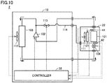
- Fig. 10 is a functional block diagram showing a configuration of a refrigerator 2 which is one example of a refrigeration cycle apparatus according to the second embodiment.
- refrigerator 2 is configured such that an on-off valve 113 and a bypass flow path 114 are added to the configuration of refrigerator 1 shown in Fig. 1 and controller 31 is replaced with a controller 32. Opening and closing of on-off valve 113 are controlled by controller 32.
- Bypass flow path 114 branches off from a flow path between compressor 102 and condenser 103, passes through on-off valve 113, and joins a flow path between expansion valve 104 and evaporator 101.
- On-off valve 113 is desirably an electromagnetic valve that can be opened and closed instantaneously.
- Fig. 11 is a flowchart for illustrating a process flow of defrosting operation performed in the second embodiment.
- S110 and S21 in Fig. 4 are replaced with S120 and S22, respectively.
- controller 32 increases the rotation speed of indoor fan 111 in S121 similarly to the first embodiment, opens on-off valve 113 in S122, and then, waits for a certain time period in S123 and moves the process to S22.
- controller 32 stops compressor 102 and indoor fan 111 (S221 and S222) and closes on-off valve 113 (S223), and moves the process to S31.
- Controller 32 heats evaporator 101 by indoor heater 121 until the defrosting end condition is satisfied (YES in S41). Thereafter, in S51, controller 32 stops indoor heater 121, and returns the process to the main routine.
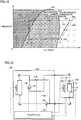
- Fig. 12 is a P-h diagram showing the relation between the pressure and the enthalpy of the refrigerant in the second embodiment.
- a cycle C20 represents circulation of the refrigerant during the defrosting shortening operation.
- an arrival point R21 of the evaporation process by evaporator 101 is higher in enthalpy than arrival point R1 of the evaporation process in cycle C1 because the rotation speed of indoor fan 111 is increased.
- the enthalpy in an adiabatic expansion process expressed as a state change from a point R23 to a point R24 in cycle C12 is higher than that in cycle C1.
- the enthalpy of the wet vapor flowing into evaporator 101 increases, and thus, vaporization of the liquid refrigerant in evaporator 101 is promoted. As a result, the amount of the liquid refrigerant in evaporator 101 can be reduced.
- the hot gas joins the wet vapor flowing into the evaporator during the defrosting shortening operation, and thus, the amount of the liquid refrigerant in the evaporator can be reduced as compared with the first embodiment.
- the length of time required for the defrosting operation can be shortened and the user's comfort can be further increased as compared with the first embodiment.
- the second embodiment has given a description of the case in which the bypass flow path is disposed so as to extend from the outdoor unit to the indoor unit.
- a modification of the second embodiment will give a description of the case in which the entire bypass flow path is arranged in the outdoor unit.
- Fig. 13 is a functional block diagram showing a configuration of a refrigerator 2A which is one example of a refrigeration cycle apparatus according to the modification of the second embodiment.
- expansion valve 104 is arranged in an outdoor unit 12A.
- a bypass flow path 114A joins a portion of a flow path between expansion valve 104 and evaporator 101 that is included in outdoor unit 12A. As a result, bypass flow path 114A as a whole is arranged in outdoor unit 12A.
- the defrosting time can be shortened and the user's comfort can be further increased as compared with the first embodiment, and the cost required for disposing the bypass flow path can be reduced.
- the first embodiment has given a description of the case in which the process of heating the evaporator by the indoor heater is executed after the defrosting shortening operation.
- a third embodiment will give a description of the case of heating the condenser by an outdoor heater during the defrosting shortening operation.
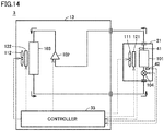
- Fig. 14 is a functional block diagram showing a configuration of a refrigerator 3 which is one example of a refrigeration cycle apparatus according to the third embodiment.
- Refrigerator 3 shown in Fig. 14 is configured such that an outdoor heater 122 is added to the configuration of refrigerator 1 in Fig. 1 and controller 31 is replaced with a controller 33. Since the remaining configuration is similar, description thereof will not be repeated.
- Outdoor heater 122 is controlled by controller 33 to heat condenser 103.
- Fig. 15 is a flowchart for illustrating a process flow of defrosting operation performed in the third embodiment.
- S110 and S21 in Fig. 4 are replaced with S130 and S23, respectively.
- controller 33 increases the rotation speed of indoor fan 111 in S131 similarly to the first embodiment, and operates outdoor heater 122 to start heating of condenser 103 in S132, and then, waits for a certain time period in S133 and moves the process to S23.
- controller 33 stops compressor 102 and indoor fan 111 (S231 and S232) and stops outdoor heater 122 (S233), and then, moves the process to S31.
- Controller 33 heats evaporator 101 by indoor heater 121 until the defrosting end condition is satisfied (YES in S41). Thereafter, in S51, controller 33 stops indoor heater 121, and returns the process to the main routine.
- Fig. 16 is a P-h diagram showing the relation between the pressure and the enthalpy of the refrigerant in the third embodiment.
- a cycle C30 represents circulation of the refrigerant during the defrosting shortening operation.
- an arrival point R31 of the evaporation process by evaporator 101 is higher in enthalpy than arrival point R1 of the evaporation process in cycle C1 because the rotation speed of indoor fan 111 is increased.
- the condensation pressure in the condensation process expressed as a state change from a point R32 to a point R33 in cycle C30 is higher than that in cycle C1 because the temperature of the refrigerant rises.
- the enthalpy in the adiabatic expansion process expressed as a state change from point R33 to a point R34 in cycle C30 is higher than that in cycle C1. Therefore, vaporization of the liquid refrigerant in the adiabatic expansion process by expansion valve 104 is promoted. As a result, the amount of the liquid refrigerant in evaporator 101 can be reduced.
- the condenser in addition to increasing the rotation speed of the indoor fan, the condenser is heated during the defrosting shortening operation, and thus, the amount of the liquid refrigerant in the evaporator can be reduced as compared with the first embodiment. As a result, the length of time required for the defrosting operation can be shortened and the user's comfort can be further increased as compared with the first embodiment.
- the first embodiment has given a description of the refrigeration cycle apparatus in which the circulation direction of the refrigerant does not change.
- a fourth embodiment will give a description of a refrigeration cycle apparatus in which the circulation direction of the refrigerant during the heating operation is opposite to the circulation direction of the refrigerant during the cooling operation.
- Fig. 17 is a functional block diagram showing a configuration of an air conditioning apparatus 4 which is one example of a refrigeration cycle apparatus according to the fourth embodiment.
- Fig. 17(a) shows a flow of the refrigerant during the heating operation.
- Fig. 17(b) shows a flow of the refrigerant during the cooling operation and the defrosting operation.
- air conditioning apparatus 4 includes an outdoor unit 14 and an indoor unit 24.
- Outdoor unit 14 includes a heat exchanger 141, a compressor 142, a four-way valve 145, an outdoor fan 151, an outdoor heater 161, a controller 34, and temperature sensors 81 and 82.
- Indoor unit 24 includes a heat exchanger 143, an expansion valve 144 and an indoor fan 152. Controller 34 may be included in indoor unit 24, or may be arranged outside outdoor unit 14 and indoor unit 24.
- Four-way valve 145 is controlled by controller 34, and during the heating operation, four-way valve 145 forms a flow path such that the refrigerant circulates through heat exchanger 141, compressor 142, heat exchanger 143, and expansion valve 144 in this order as shown in Fig. 17(a) .
- four-way valve 145 forms a flow path such that the refrigerant circulates through compressor 142, heat exchanger 141, expansion valve 144, and heat exchanger 143 in this order as shown in Fig. 17(b) .
- Compressor 142 compresses low-pressure gas refrigerant and outputs high-pressure gas refrigerant.
- Heat exchanger 141 functions as a condenser during the cooling operation and the defrosting operation, and functions as an evaporator during the heating operation.
- Outdoor fan 151 blows air into heat exchanger 141.
- Outdoor heater 161 operates during the defrosting operation to heat heat exchanger 141.
- Temperature sensor 81 is disposed in a pipe of heat exchanger 141 and outputs the detected pipe temperature to controller 34.
- Temperature sensor 82 is disposed near an air inlet of heat exchanger 141 and outputs the detected air temperature to controller 34.
- Expansion valve 144 adiabatically expands and decompresses liquid refrigerant and discharges wet vapor.
- a linear expansion valve (LEV) can, for example, be used as expansion valve 144.
- Heat exchanger 143 functions as an evaporator during the cooling operation and the defrosting operation, and functions as a condenser during the heating operation.
- Indoor fan 152 blows air into heat exchanger 143.
- Controller 34 controls a driving frequency of compressor 142 to thereby control an amount of the refrigerant discharged by compressor 142 per unit time. Controller 34 obtains the pipe temperature of heat exchanger 141 from temperature sensor 81. Controller 34 obtains the temperature of the air taken into heat exchanger 141 from temperature sensor 82. Controller 34 adjusts a rotation speed of each of outdoor fan 151 and indoor fan 152 to thereby control an amount of air blown by each of outdoor fan 151 and indoor fan 152 per unit time.
- frost may in some cases form on heat exchanger 141 arranged in outdoor unit 14 having a low outdoor air temperature and functioning as an evaporator that deprives the outdoor air of heat.
- the defrosting operation is performed, with the heating operation being interrupted. Defrosting in the fourth embodiment is performed by heating heat exchanger 141 by outdoor heater 161 and causing the refrigerant to flow reversely to the refrigerant flow during the heating operation, without stopping the compressor, and causing heat exchanger 141 to function as a condenser to thereby release heat.
- Fig. 18 is a flowchart for illustrating a process flow of defrosting operation performed in the fourth embodiment.
- controller 34 determines as the defrosting start condition whether or not a difference between the air temperature at the air inlet of heat exchanger 141 and the evaporation temperature is greater than a reference value ⁇ Te4.
- ⁇ Te4 reference value
- controller 34 returns the process to the main routine because the air temperature around heat exchanger 141 is sufficiently reduced by heat exchange between the air around heat exchanger 141 and the liquid refrigerant.
- controller 34 moves the process to S141 because the heat exchange efficiency of heat exchanger 141 decreases due to formation of frost and thus the air conditioning capacity of air conditioning apparatus 4 decreases and continuation of the heating operation becomes difficult.
- controller 34 increases the rotation speed of outdoor fan 151, and moves the process to S142.
- controller 34 waits for a certain time period, and moves the process to S24.
- controller 34 controls four-way valve 145 to switch the circulation direction of the refrigerant from the circulation direction during the heating operation to the circulation direction during the defrosting operation, and moves the process to S34.
- controller 34 operates outdoor heater 161 to heat heat exchanger 141 in S34, and moves the process to S44.
- controller 34 determines as the defrosting end condition whether or not the pipe temperature of heat exchanger 141 is higher than a reference temperature Tdef4.
- controller 34 returns the process to S34 because heating of heat exchanger 141 is insufficient.
- controller 34 moves the process to S541 because heat exchanger 141 is sufficiently heated and defrosting is completed. Controller 34 stops outdoor heater 161 in S541, and then, controls the four-way valve to switch the circulation direction of the refrigerant from the circulation direction during the defrosting operation to the circulation direction during the heating operation in S542, and returns the process to the main routine.
- the rotation speed of the outdoor fan is increased during the defrosting shortening operation, and thus, the amount of the liquid refrigerant in the heat exchanger subjected to defrosting can be reduced, also in the refrigeration cycle apparatus in which the circulation direction of the refrigerant during the heating operation is opposite to the circulation direction of the refrigerant during the cooling operation.
- the length of time required for the defrosting operation can be shortened and the user's comfort can be increased.
- a fifth embodiment will give a description of a configuration in which the hot gas output from the compressor joins a flow path connecting the expansion valve and the heat exchanger functioning as an evaporator.
- the hot gas to increase the enthalpy of the wet vapor flowing into the heat exchanger functioning as an evaporator, vaporization of the liquid refrigerant in the heat exchanger is promoted. As a result, the amount of the liquid refrigerant in the heat exchanger functioning as an evaporator can be reduced.
- Fig. 19 is a functional block diagram showing a configuration of an air conditioning apparatus 5 which is one example of a refrigeration cycle apparatus according to the fifth embodiment.
- air conditioning apparatus 5 is configured such that an on-off valve 213 and a bypass flow path 214 are added to the configuration of air conditioning apparatus 4 shown in Fig. 17(a) and controller 34 is replaced with a controller 35. Opening and closing of on-off valve 213 are controlled by controller 35.
- Bypass flow path 214 branches off from a flow path between compressor 142 and heat exchanger 143, passes through on-off valve 213, and joins a flow path between expansion valve 144 and heat exchanger 141.
- On-off valve 213 is desirably an electromagnetic valve that can be opened and closed instantaneously.
- Fig. 20 is a flowchart for illustrating a process flow of defrosting operation performed in the fifth embodiment.
- S140 and S24 in Fig. 18 are replaced with S150 and S25, respectively.
- controller 35 increases the rotation speed of outdoor fan 151 in S151 similarly to the fourth embodiment, and opens on-off valve 213 in S152, and then, waits for a certain time period in S153 and moves the process to S251.
- Controller 35 closes on-off valve 213 in S251, and then, controls four-way valve 145 to switch the circulation direction of the refrigerant in S252 and moves the process to S34.
- Controller 35 heats heat exchanger 141 by outdoor heater 161 until the defrosting end condition is satisfied (YES in S44). Thereafter, controller 35 stops outdoor heater 161 in S541, and then, controls four-way valve 145 to switch the circulation direction of the refrigerant in S542, and returns the process to the main routine.
- the hot gas joins the wet vapor flowing into the heat exchanger functioning as an evaporator during the defrosting shortening operation, and thus, the amount of the liquid refrigerant in the heat exchanger can be reduced as compared with the fourth embodiment.
- the length of time required for the defrosting operation can be shortened and the user's comfort can be further increased as compared with the fourth embodiment.
- the fourth and fifth embodiments have given a description of the case in which the process of heating the heat exchanger functioning as an evaporator by the outdoor heater is executed during the defrosting shortening operation.
- the circulation direction of the refrigerant is reversed during the defrosting operation, and thus, the heat exchanger subjected to defrosting functions as a condenser to thereby release heat. Therefore, the consumed power is suppressed, and thus, heating by the outdoor heater is not necessarily required during the defrosting operation.
- the first to fifth embodiments have given a description of the case in which the refrigeration cycle apparatus includes one outdoor unit and one indoor unit.
- the refrigeration cycle apparatus according to the present invention may include a plurality of outdoor units, or may include a plurality of indoor units.
Landscapes
- Engineering & Computer Science (AREA)
- Physics & Mathematics (AREA)
- Mechanical Engineering (AREA)
- Thermal Sciences (AREA)
- General Engineering & Computer Science (AREA)
- Chemical & Material Sciences (AREA)
- Combustion & Propulsion (AREA)
- Air Conditioning Control Device (AREA)
- Defrosting Systems (AREA)
Abstract
Description
- The present invention relates to a refrigeration cycle apparatus configured to perform defrosting operation.
- A refrigeration cycle apparatus configured to perform defrosting operation (defrost) for melting and removing frost formed on an evaporator has been conventionally known. For example, Japanese Patent Laying-Open No.
5-34049 - PTL 1: Japanese Patent Laying-Open No.
5-34049 - Both liquid refrigerant and gas refrigerant exist in an evaporator. When an amount of the liquid refrigerant in the evaporator is large at the start of the defrosting operation, an amount of heat used to vaporize the liquid refrigerant, of an amount of heat generated to melt frost, is large, and thus, an amount of heat used to melt frost is reduced. As a result, a longer length of time is required for the defrosting operation. The length of time required for the defrosting operation corresponds to the interruption time of normal operation, and thus, it is desirable that the length of time required for the defrosting operation should be short. However, Japanese Patent Laying-Open No.
5-34049 - The present invention has been made to solve the above-described problem, and an object of the present invention is to shorten a length of time required for defrosting operation.
- A refrigeration cycle apparatus according to the present invention is configured to circulate refrigerant in a first circulation direction in order of a first heat exchanger, a compressor, a second heat exchanger, and an expansion valve, and perform defrosting operation when a start condition for the defrosting operation is satisfied. The refrigeration cycle apparatus includes: a first blower; and a controller. The first blower is configured to blow air into the first heat exchanger. The controller is configured to control an amount of air blown by the first blower. The controller is configured to increase the amount of air blown by the first blower per unit time, when the start condition is satisfied.
- In the refrigeration cycle apparatus according to the present invention, the amount of air blown by the first blower per unit time is larger after the start condition for the defrosting operation is satisfied than before the start condition is satisfied. Therefore, the heat exchange efficiency of an evaporator after the start condition for the defrosting operation is satisfied is increased and vaporization of liquid refrigerant is promoted. Since the defrosting operation is performed with an amount of the liquid refrigerant in the evaporator being small, an amount of heat used to melt frost, of an amount of heat used for defrosting, is large. As a result, the length of time required for the defrosting operation, i.e., the interruption time of normal operation, can be shortened and the user's comfort can be increased.
-
-
Fig. 1 is a functional block diagram showing a configuration of a refrigerator which is one example of a refrigeration cycle apparatus according to a first embodiment. -
Fig. 2 is a flowchart for illustrating one example of a process flow of defrosting operation performed in a general refrigeration cycle apparatus. -
Fig. 3 is a flowchart for illustrating an overview of a process flow of defrosting operation performed in the first embodiment. -
Fig. 4 is a flowchart for illustrating the process flow of the defrosting operation performed in the first embodiment. -
Fig. 5 is a P-h diagram showing the relation between the pressure and the enthalpy of refrigerant in the first embodiment. -
Fig. 6 is a flowchart for illustrating a process flow of defrosting operation performed in a first modification of the first embodiment. -
Fig. 7 is a flowchart for illustrating a process flow of defrosting operation performed in a second modification of the first embodiment. -
Fig. 8 is a P-h diagram showing the relation between the pressure and the enthalpy of refrigerant in the second modification of the first embodiment. -
Fig. 9 is a flowchart for illustrating a process flow of defrosting operation performed in a third modification of the first embodiment. -
Fig. 10 is a functional block diagram showing a configuration of a refrigerator which is one example of a refrigeration cycle apparatus according to a second embodiment. -
Fig. 11 is a flowchart for illustrating a process flow of defrosting operation performed in the second embodiment. -
Fig. 12 is a P-h diagram showing the relation between the pressure and the enthalpy of refrigerant in the second embodiment. -
Fig. 13 is a functional block diagram showing a configuration of a refrigerator which is one example of a refrigeration cycle apparatus according to a modification of the second embodiment. -
Fig. 14 is a functional block diagram showing a configuration of a refrigerator which is one example of a refrigeration cycle apparatus according to a third embodiment. -
Fig. 15 is a flowchart for illustrating a process flow of defrosting operation performed in the third embodiment. -
Fig. 16 is a P-h diagram showing the relation between the pressure and the enthalpy of refrigerant in the third embodiment. -
Fig. 17 is a functional block diagram showing a configuration of an air conditioning apparatus which is one example of the refrigeration cycle apparatus according to a fourth embodiment. -
Fig. 18 is a flowchart for illustrating a process flow of defrosting operation performed in the fourth embodiment. -
Fig. 19 is a functional block diagram showing a configuration of an air conditioning apparatus which is one example of a refrigeration cycle apparatus according to a fifth embodiment. -
Fig. 20 is a flowchart for illustrating a process flow of defrosting operation performed in the fifth embodiment. - Embodiments of the present invention will be described in detail hereinafter with reference to the drawings, in which the same or corresponding portions are denoted by the same reference characters and description thereof will not be repeated in principle.
-
Fig. 1 is a functional block diagram showing a configuration of arefrigerator 1 which is one example of a refrigeration cycle apparatus according to a first embodiment. As shown inFig. 1 ,refrigerator 1 includes anoutdoor unit 11 and anindoor unit 21. -
Outdoor unit 11 includes acompressor 102, acondenser 103, anoutdoor fan 112, and acontroller 31.Indoor unit 21 includes anevaporator 101, anexpansion valve 104, anindoor fan 111, anindoor heater 121, andtemperature sensors Controller 31 may be included inindoor unit 21, or may be arranged outsideoutdoor unit 11 andindoor unit 21. - In
refrigerator 1, refrigerant circulates throughevaporator 101,compressor 102,condenser 103, andexpansion valve 104 in this order. -
Compressor 102 compresses low-pressure gas refrigerant received fromevaporator 101, and outputs high-pressure gas refrigerant to condenser 103.Condenser 103 receives and condenses the high-temperature and high-pressure gas refrigerant fromcompressor 102, and discharges liquid refrigerant toexpansion valve 104. Heat (condensation heat) generated when the gas refrigerant condenses to the liquid refrigerant is released fromcondenser 103.Outdoor fan 112 blows air intocondenser 103. -
Expansion valve 104 adiabatically expands and decompresses the liquid refrigerant fromcondenser 103, and discharges wet vapor toevaporator 101. A linear expansion valve (LEV) can, for example, be used asexpansion valve 104. Evaporator 101 receives the wet vapor fromexpansion valve 104, evaporates the liquid refrigerant included in the wet vapor, and discharges gas refrigerant tocompressor 102. Inevaporator 101, the liquid refrigerant deprives the indoor air of heat (vaporization heat) and evaporates.Indoor fan 111 blows air intoevaporator 101.Indoor heater 121 operates during defrosting operation to heatevaporator 101.Temperature sensor 41 is disposed in a pipe ofevaporator 101 and outputs the detected pipe temperature tocontroller 31.Temperature sensor 42 is disposed near an air inlet ofevaporator 101 and outputs the detected air temperature tocontroller 31. -
Controller 31 controls a driving frequency ofcompressor 102 to thereby control an amount of the refrigerant discharged bycompressor 102 per unit time.Controller 31 obtains the pipe temperature ofevaporator 101 fromtemperature sensor 41.Controller 31 obtains the temperature of the air taken intoevaporator 101 fromtemperature sensor 42.Controller 31 adjusts a rotation speed of each ofindoor fan 111 andoutdoor fan 112 to thereby control an amount of air blown by each ofindoor fan 111 andoutdoor fan 112 per unit time.Controller 31 has a control unit (not shown) including a processor such as, for example, a CPU (Central Processing Unit). The controller has a storage unit (not shown) including a nonvolatile memory such as, for example, a flash memory. The storage unit can store, for example, an OS (Operating System) read and executed by the control unit, programs for various applications (e.g., a program for controlling the defrosting operation), and various types of data used by the programs. - In the first embodiment, during normal operation, frost may in some cases form on
evaporator 101 arranged inindoor unit 21 having a low room temperature. Defrosting in the first embodiment is performed by stoppingcompressor 102 andheating evaporator 101 byindoor heater 121. -
Fig. 2 is a flowchart for illustrating one example of a process flow of defrosting operation performed in a general refrigeration cycle apparatus. The process shown inFig. 2 is executed at certain time intervals by a not-shown main routine. Hereinafter, a step will be simply indicated as "S". - As shown in
Fig. 2 , in S11, the controller determines whether or not a defrosting start condition is satisfied. The defrosting start condition may be any condition as long as it is a condition indicating that the heat exchange efficiency of the evaporator falls below a reference value. Examples of the defrosting start condition can include a condition that a difference between the air temperature near the inlet ofevaporator 101 and an evaporation temperature is greater than a prescribed value. When the defrosting start condition is not satisfied (NO in S11), the controller returns the process to the main routine. When the defrosting start condition is satisfied (YES in S11), the controller moves the process to S21. - In S21, the controller performs defrosting preparation operation, and moves the process to S31. In S31, the controller heats the evaporator for a certain time period, and moves the process to S41. Examples of a method for heating the evaporator can include a method for heating the evaporator by a heater, a method for heating the evaporator by the outdoor air, and a method for causing backflow of the refrigerant and causing the heat exchanger functioning as an evaporator to function as a condenser to thereby generate heat.
- In S41, the controller determines whether or not a defrosting end condition is satisfied. Examples of the defrosting end condition can include a condition that the pipe temperature of the evaporator is higher than a prescribed temperature. When the defrosting end condition is not satisfied (NO in S41), the controller returns the process to S31. When the defrosting end condition is satisfied (YES in S41), the controller moves the process to S51. In S51, the controller executes the defrosting end process, and returns the process to the main routine.
- Both the liquid refrigerant and the gas refrigerant exist in the evaporator. When an amount of the liquid refrigerant in the evaporator is large at the start of the defrosting operation, an amount of heat used to vaporize the liquid refrigerant, of an amount of heat generated to melt frost, is large, and thus, an amount of heat used to melt frost is reduced. As a result, a longer length of time is required for the defrosting operation. The length of time required for the defrosting operation corresponds to the interruption time of the normal operation, and thus, it is desirable that the length of time required for the defrosting operation should be short.
- Accordingly, in the first embodiment, the amount of the liquid refrigerant in the evaporator is reduced and an operation for shortening the defrosting time (defrosting shortening operation) is performed.
Fig. 3 is a flowchart for illustrating an overview of a process flow of defrosting operation performed in the first embodiment. As shown inFig. 3 , in the first embodiment, the defrosting shortening operation (S110) is performed after the defrosting start condition is satisfied and before the defrosting preparation operation is performed. The defrosting shortening operation is performed prior to heating of the evaporator (S31), and thus, the liquid refrigerant in the evaporator can be reduced and the length of time required for heating of the evaporator can be shortened. As a result, the length of time required for the defrosting operation, i.e., the interruption time of the normal operation, can be shortened and the user's comfort can be increased. - In the first embodiment, during the defrosting shortening operation, the rotation speed of
indoor fan 111 is increased and the amount of air blown byindoor fan 111 per unit time is increased to be larger than the amount of air before the defrosting start condition is satisfied. The heat exchange efficiency ofevaporator 101 is increased and vaporization of the liquid refrigerant is promoted. As a result, the amount of the liquid refrigerant inevaporator 101 is reduced. -
Fig. 4 is a flowchart for illustrating a process flow of the defrosting operation performed in the first embodiment. As shown inFig. 4 , in S11,controller 31 determines as the defrosting start condition whether or not the difference between the air temperature at the air inlet ofevaporator 101 and the evaporation temperature is greater than a reference value ΔTe1. When the difference between the air temperature at the air inlet ofevaporator 101 and the evaporation temperature is equal to or smaller than reference value ΔTe1 (NO in S11),controller 31 returns the process to the main routine because the room temperature can be reduced to a target temperature by heat exchange between the air aroundevaporator 101 and the liquid refrigerant. When the difference between the air temperature at the air inlet ofevaporator 101 and the evaporation temperature is greater than reference value ΔTe1 (YES in S11),controller 31 moves the process to S112 because the heat exchange efficiency ofevaporator 101 decreases due to formation of frost and the room temperature cannot be reduced to the target temperature even if the normal operation is continued. - In S112,
controller 31 increases the rotation speed ofindoor fan 111 to thereby increase the amount of air blown byindoor fan 111 per unit time, and moves the process to S114. In S114,controller 31 waits for a certain time period, and moves the process to S211. During waiting for the certain time period, the amount of the liquid refrigerant inevaporator 101 is reduced. Howlong controller 31 waits in S114 can be determined as appropriate by real machine experiment or simulation. - In S211,
controller 31 stopscompressor 102, and moves the process to S212. In S212,controller 31 stopsindoor fan 111 to prevent the air heated byindoor heater 121 from being discharged fromindoor unit 21, and moves the process to S31. - In order to melt frost formed on
evaporator 101,controller 31 operatesindoor heater 121 to heatevaporator 101, and moves the process to S41. - In S41,
controller 31 determines as the defrosting end condition whether or not the pipe temperature ofevaporator 101 is higher than a reference temperature Tdef1. When the pipe temperature ofevaporator 101 is equal to or lower than reference temperature Tdef1 (NO in S41),controller 31 returns the process to S31 because heating ofevaporator 101 is insufficient. When the pipe temperature ofevaporator 101 is higher than reference temperature Tdef1 (YES in S41),controller 31 moves the process to S51 becauseevaporator 101 is sufficiently heated and defrosting is completed. In S51,controller 31 stopsindoor heater 121, and returns the process to the main routine. -
Fig. 5 is a P-h diagram showing the relation between the pressure and the enthalpy of the refrigerant in the first embodiment. InFig. 5 , a curve LC1 represents a saturated liquid line of the refrigerant. A curve GC1 represents a saturated vapor line of the refrigerant. A point CP1 represents a critical point of the refrigerant. The critical point is a point indicating a limit of a range in which a phase change between the liquid refrigerant and the gas refrigerant can occur, and is an intersection point of the saturated liquid line and the saturated vapor line. When the pressure of the refrigerant becomes higher than the pressure at the critical point, the phase change between the liquid refrigerant and the gas refrigerant no longer occurs. In a region lower in enthalpy than the saturated liquid line, the refrigerant is in a liquid state. In a region sandwiched between the saturated liquid line and the saturated vapor line, the refrigerant is in a gas-liquid two-phase state (wet vapor). In a region higher in enthalpy than the saturated vapor line, the refrigerant is in a gas state. - In
Fig. 5 , a cycle C1 represents circulation of the refrigerant during the normal operation. A process of a state change from a point R1 to a point R2 represents a process of compression of the refrigerant bycompressor 102. A process of a state change from point R2 to a point R3 represents a process of condensation bycondenser 103. A process of a state change from point R3 to a point R4 represents a process of adiabatic expansion byexpansion valve 104. A process of a state change from point R4 to point R1 represents a process of evaporation byevaporator 101. - In
Fig. 5 , a cycle C10 represents circulation of the refrigerant during the defrosting shortening operation. As shown inFig. 5 , an arrival point R11 of the evaporation process byevaporator 101 in cycle C10 is higher in enthalpy than an arrival point R1 of the evaporation process in cycle C1. That is, cycle C10 is higher in degree of superheating than cycle C1. This is because, by increasing the rotation speed ofindoor fan 111 during the defrosting shortening operation, the heat exchange efficiency ofevaporator 101 is increased and vaporization of the liquid refrigerant is promoted, and thus, the amount of the liquid refrigerant inevaporator 101 decreases and an amount of heat absorbed into the gas refrigerant inevaporator 101 during the evaporation process increases. - As described above, according to the first embodiment, the amount of air blown by the indoor fan per unit time after the start condition for the defrosting operation is satisfied is increased to be larger than the amount of air before the start condition is satisfied, and thus, the amount of the liquid refrigerant in the evaporator can be reduced. As a result, the length of time required for the defrosting operation can be shortened and the user's comfort can be increased.
- The first embodiment has given a description of the case of increasing the rotation speed of the indoor fan in order to reduce the amount of the liquid refrigerant in the evaporator. The process for reducing the amount of the liquid refrigerant in the evaporator is not limited to increasing the rotation speed of the indoor fan. By combining another process with increasing the rotation speed of the indoor fan, the defrosting time can be further shortened. Three modifications will be described below, in which other processes are executed during the defrosting shortening operation, in addition to increasing the rotation speed of the indoor fan.
- In a first modification of the first embodiment, in addition to increasing the rotation speed of the indoor fan, a degree of opening of the expansion valve is decreased during the defrosting shortening operation. By decreasing the degree of opening of the expansion valve, an amount of the wet vapor flowing into the evaporator decreases. As a result, the amount of the liquid refrigerant in the evaporator can be reduced.
- A difference between the first embodiment and the first modification is a process flow of the defrosting operation. That is,
Fig. 4 is replaced withFig. 6 . Since the remaining configuration is similar, description will not be repeated. -
Fig. 6 is a flowchart for illustrating a process flow of defrosting operation performed in the first modification of the first embodiment. In the flowchart shown inFig. 6 , S110 inFig. 4 is replaced with S110A. - As shown in
Fig. 6 , when the defrosting start condition is satisfied in S11, the controller decreases the degree of opening ofexpansion valve 104 to be lower than the degree of opening before the defrosting start condition is satisfied in S111. Thereafter, similarly to the first embodiment, the controller increases the rotation speed ofindoor fan 111 in S112, waits for a certain time period in S114, and moves the process to S21. In S21, the controller stops compressor 102 (S211) and stops indoor fan 111 (S212), and moves the process to S31. - The controller heats
evaporator 101 byindoor heater 121 until the defrosting end condition is satisfied (YES in S41). Thereafter, in S51, the controller stopsindoor heater 121, and returns the process to the main routine. - As described above, according to the first modification of the first embodiment, in addition to increasing the rotation speed of the indoor fan, the degree of opening of
expansion valve 104 is decreased during the defrosting shortening operation, and thus, the amount of the liquid refrigerant in the evaporator can be reduced as compared with the first embodiment. As a result, the length of time required for the defrosting operation can be shortened and the user's comfort can be further increased as compared with the first embodiment. - In a second modification of the first embodiment, in addition to increasing the rotation speed of the indoor fan, the rotation speed of the outdoor fan is increased during the defrosting shortening operation. By increasing the rotation speed of the outdoor fan, the heat exchange efficiency of the condenser increases. Condensation of the gas refrigerant is promoted, and thus, an amount of the gas refrigerant in the condenser decreases and a condensation pressure decreases. Therefore, a pressure difference of the refrigerant before and after the refrigerant passes through the expansion valve (differential pressure of the expansion valve) decreases. When the differential pressure of the expansion valve decreases, an amount of the refrigerant passing through the expansion valve decreases and an amount of the refrigerant flowing into the evaporator decreases. As a result, the amount of the liquid refrigerant in the evaporator can be reduced.
- A difference between the first embodiment and the second modification is a process flow of defrosting operation and a P-h diagram. That is,
Figs. 4 and5 are replaced withFigs. 7 and8 , respectively. Since the remaining configuration is similar, description will not be repeated. -
Fig. 7 is a flowchart for illustrating a process flow of defrosting operation performed in the second modification of the first embodiment. In the flowchart shown inFig. 7 , S110 and S21 inFig. 4 are replaced with S110B and S21B. - As shown in
Fig. 7 , when the defrosting start condition is satisfied in S11, the controller increases the rotation speed ofindoor fan 111 in S112 similarly to the first embodiment, increases the rotation speed ofoutdoor fan 112 in S113, and then, waits for a certain time period in S114 and moves the process to S21B. In S21B, the controller stops compressor 102 (S211) and stopsindoor fan 111 and outdoor fan 112 (S212 and S213), and moves the process to S31. - The controller heats
evaporator 101 by indoor heater 121 (S31) until the defrosting end condition is satisfied (YES in S41). Thereafter, in S51, the controller stopsindoor heater 121, and returns the process to the main routine. -
Fig. 8 is a P-h diagram showing the relation between the pressure and the enthalpy of the refrigerant in the second modification of the first embodiment. InFig. 8 , a cycle C12 represents circulation of the refrigerant during the defrosting shortening operation. As shown inFig. 8 , similarly to the first embodiment, an arrival point R11B of the evaporation process byevaporator 101 is higher in enthalpy than arrival point R1 of the evaporation process in cycle C1 because the rotation speed ofindoor fan 111 is increased. In the second modification of the first embodiment, as the effect of increasing the rotation speed ofoutdoor fan 112, a pressure (condensation pressure) in a condensation process expressed as a state change from a point R12B to a point R13 is lower than that in cycle C1. When the condensation pressure decreases, the differential pressure ofexpansion valve 104 decreases and the amount of the refrigerant passing throughexpansion valve 104 decreases. As a result, the amount of the refrigerant flowing intoevaporator 101 decreases, and thus, the amount of the liquid refrigerant inevaporator 101 can be reduced. - As described above, according to the second modification of the first embodiment, in addition to increasing the rotation speed of the indoor fan, the rotation speed of the outdoor fan is increased during the defrosting shortening operation, and thus, the amount of the liquid refrigerant in the evaporator can be reduced as compared with the first embodiment. As a result, the length of time required for the defrosting operation can be shortened and the user's comfort can be further increased as compared with the first embodiment.
- In a third modification of the first embodiment, as shown by S110C in
Fig. 9 , in addition to increasing the rotation speed of the indoor fan, the degree of opening of the expansion valve is decreased and the rotation speed of the outdoor fan is increased during the defrosting shortening operation. According to the third modification of the first embodiment, the amount of the liquid refrigerant in the evaporator can be reduced during the defrosting shortening operation as compared with the first and second modifications of the first embodiment. As a result, the length of time required for the defrosting operation can be shortened and the user's comfort can be further increased as compared with the first and second modifications of the first embodiment. - A second embodiment will give a description of a configuration in which the high-temperature gas refrigerant (hot gas) output from the compressor joins a flow path connecting the expansion valve and the evaporator during the defrosting shortening operation. By increasing the enthalpy of the wet vapor flowing into the evaporator due to the high-temperature refrigerant, vaporization of the liquid refrigerant in the evaporator is promoted. As a result, the amount of the liquid refrigerant in the evaporator can be reduced.
-
Fig. 10 is a functional block diagram showing a configuration of arefrigerator 2 which is one example of a refrigeration cycle apparatus according to the second embodiment. As shown inFig. 10 ,refrigerator 2 is configured such that an on-offvalve 113 and abypass flow path 114 are added to the configuration ofrefrigerator 1 shown inFig. 1 andcontroller 31 is replaced with acontroller 32. Opening and closing of on-offvalve 113 are controlled bycontroller 32.Bypass flow path 114 branches off from a flow path betweencompressor 102 andcondenser 103, passes through on-offvalve 113, and joins a flow path betweenexpansion valve 104 andevaporator 101. On-offvalve 113 is desirably an electromagnetic valve that can be opened and closed instantaneously. -
Fig. 11 is a flowchart for illustrating a process flow of defrosting operation performed in the second embodiment. In the flowchart shown inFig. 11 , S110 and S21 inFig. 4 are replaced with S120 and S22, respectively. As shown inFig. 11 , when the defrosting start condition is satisfied in S11,controller 32 increases the rotation speed ofindoor fan 111 in S121 similarly to the first embodiment, opens on-offvalve 113 in S122, and then, waits for a certain time period in S123 and moves the process to S22. In S22,controller 32 stopscompressor 102 and indoor fan 111 (S221 and S222) and closes on-off valve 113 (S223), and moves the process to S31.Controller 32 heats evaporator 101 byindoor heater 121 until the defrosting end condition is satisfied (YES in S41). Thereafter, in S51,controller 32 stopsindoor heater 121, and returns the process to the main routine. -
Fig. 12 is a P-h diagram showing the relation between the pressure and the enthalpy of the refrigerant in the second embodiment. InFig. 12 , a cycle C20 represents circulation of the refrigerant during the defrosting shortening operation. As shown inFig. 12 , similarly to the first embodiment, an arrival point R21 of the evaporation process byevaporator 101 is higher in enthalpy than arrival point R1 of the evaporation process in cycle C1 because the rotation speed ofindoor fan 111 is increased. In the second embodiment, as the effect of allowing the hot gas to join the wet vapor flowing intoevaporator 101, the enthalpy in an adiabatic expansion process expressed as a state change from a point R23 to a point R24 in cycle C12 is higher than that in cycle C1. The enthalpy of the wet vapor flowing intoevaporator 101 increases, and thus, vaporization of the liquid refrigerant inevaporator 101 is promoted. As a result, the amount of the liquid refrigerant inevaporator 101 can be reduced. - As described above, according to the second embodiment, in addition to increasing the rotation speed of the indoor fan, the hot gas joins the wet vapor flowing into the evaporator during the defrosting shortening operation, and thus, the amount of the liquid refrigerant in the evaporator can be reduced as compared with the first embodiment. As a result, the length of time required for the defrosting operation can be shortened and the user's comfort can be further increased as compared with the first embodiment.
- The second embodiment has given a description of the case in which the bypass flow path is disposed so as to extend from the outdoor unit to the indoor unit. A modification of the second embodiment will give a description of the case in which the entire bypass flow path is arranged in the outdoor unit. By arranging the entire bypass flow path in the outdoor unit, a length of a pipe of the bypass flow path can be reduced. In addition, the work for disposing the pipe so as to extend from the outdoor unit to the indoor unit can be omitted. As a result, the cost required for disposing the bypass flow path can be reduced.
-
Fig. 13 is a functional block diagram showing a configuration of arefrigerator 2A which is one example of a refrigeration cycle apparatus according to the modification of the second embodiment. Inrefrigerator 2A shown inFig. 13 ,expansion valve 104 is arranged in anoutdoor unit 12A. Abypass flow path 114A joins a portion of a flow path betweenexpansion valve 104 andevaporator 101 that is included inoutdoor unit 12A. As a result,bypass flow path 114A as a whole is arranged inoutdoor unit 12A. - As described above, according to the modification of the second embodiment, similarly to the second embodiment, the defrosting time can be shortened and the user's comfort can be further increased as compared with the first embodiment, and the cost required for disposing the bypass flow path can be reduced.
- The first embodiment has given a description of the case in which the process of heating the evaporator by the indoor heater is executed after the defrosting shortening operation. A third embodiment will give a description of the case of heating the condenser by an outdoor heater during the defrosting shortening operation. By heating the condenser during the defrosting shortening operation, the enthalpy of the liquid refrigerant output from the condenser increases, and thus, vaporization of the liquid refrigerant in the adiabatic expansion process by the expansion valve is promoted. As a result, the amount of the liquid refrigerant in the evaporator can be reduced.
-
Fig. 14 is a functional block diagram showing a configuration of arefrigerator 3 which is one example of a refrigeration cycle apparatus according to the third embodiment.Refrigerator 3 shown inFig. 14 is configured such that anoutdoor heater 122 is added to the configuration ofrefrigerator 1 inFig. 1 andcontroller 31 is replaced with acontroller 33. Since the remaining configuration is similar, description thereof will not be repeated.Outdoor heater 122 is controlled bycontroller 33 to heatcondenser 103. -
Fig. 15 is a flowchart for illustrating a process flow of defrosting operation performed in the third embodiment. In the flowchart shown inFig. 15 , S110 and S21 inFig. 4 are replaced with S130 and S23, respectively. As shown inFig. 15 , when the defrosting start condition is satisfied in S11,controller 33 increases the rotation speed ofindoor fan 111 in S131 similarly to the first embodiment, and operatesoutdoor heater 122 to start heating ofcondenser 103 in S132, and then, waits for a certain time period in S133 and moves the process to S23. In S23,controller 33 stopscompressor 102 and indoor fan 111 (S231 and S232) and stops outdoor heater 122 (S233), and then, moves the process to S31.Controller 33 heats evaporator 101 byindoor heater 121 until the defrosting end condition is satisfied (YES in S41). Thereafter, in S51,controller 33 stopsindoor heater 121, and returns the process to the main routine. -
Fig. 16 is a P-h diagram showing the relation between the pressure and the enthalpy of the refrigerant in the third embodiment. InFig. 16 , a cycle C30 represents circulation of the refrigerant during the defrosting shortening operation. As shown inFig. 16 , similarly to the first embodiment, an arrival point R31 of the evaporation process byevaporator 101 is higher in enthalpy than arrival point R1 of the evaporation process in cycle C1 because the rotation speed ofindoor fan 111 is increased. In the third embodiment, as the effect ofheating condenser 103 byoutdoor heater 122, firstly, the condensation pressure in the condensation process expressed as a state change from a point R32 to a point R33 in cycle C30 is higher than that in cycle C1 because the temperature of the refrigerant rises. In addition, the enthalpy in the adiabatic expansion process expressed as a state change from point R33 to a point R34 in cycle C30 is higher than that in cycle C1. Therefore, vaporization of the liquid refrigerant in the adiabatic expansion process byexpansion valve 104 is promoted. As a result, the amount of the liquid refrigerant inevaporator 101 can be reduced. - As described above, according to the third embodiment, in addition to increasing the rotation speed of the indoor fan, the condenser is heated during the defrosting shortening operation, and thus, the amount of the liquid refrigerant in the evaporator can be reduced as compared with the first embodiment. As a result, the length of time required for the defrosting operation can be shortened and the user's comfort can be further increased as compared with the first embodiment.
- The first embodiment has given a description of the refrigeration cycle apparatus in which the circulation direction of the refrigerant does not change. A fourth embodiment will give a description of a refrigeration cycle apparatus in which the circulation direction of the refrigerant during the heating operation is opposite to the circulation direction of the refrigerant during the cooling operation.
-
Fig. 17 is a functional block diagram showing a configuration of anair conditioning apparatus 4 which is one example of a refrigeration cycle apparatus according to the fourth embodiment.Fig. 17(a) shows a flow of the refrigerant during the heating operation.Fig. 17(b) shows a flow of the refrigerant during the cooling operation and the defrosting operation. - As shown in
Fig. 17 ,air conditioning apparatus 4 includes anoutdoor unit 14 and anindoor unit 24.Outdoor unit 14 includes aheat exchanger 141, acompressor 142, a four-way valve 145, anoutdoor fan 151, anoutdoor heater 161, acontroller 34, andtemperature sensors Indoor unit 24 includes aheat exchanger 143, anexpansion valve 144 and anindoor fan 152.Controller 34 may be included inindoor unit 24, or may be arranged outsideoutdoor unit 14 andindoor unit 24. - Four-
way valve 145 is controlled bycontroller 34, and during the heating operation, four-way valve 145 forms a flow path such that the refrigerant circulates throughheat exchanger 141,compressor 142,heat exchanger 143, andexpansion valve 144 in this order as shown inFig. 17(a) . During the cooling operation and the defrosting operation, four-way valve 145 forms a flow path such that the refrigerant circulates throughcompressor 142,heat exchanger 141,expansion valve 144, andheat exchanger 143 in this order as shown inFig. 17(b) . -
Compressor 142 compresses low-pressure gas refrigerant and outputs high-pressure gas refrigerant.Heat exchanger 141 functions as a condenser during the cooling operation and the defrosting operation, and functions as an evaporator during the heating operation.Outdoor fan 151 blows air intoheat exchanger 141.Outdoor heater 161 operates during the defrosting operation to heatheat exchanger 141.Temperature sensor 81 is disposed in a pipe ofheat exchanger 141 and outputs the detected pipe temperature tocontroller 34.Temperature sensor 82 is disposed near an air inlet ofheat exchanger 141 and outputs the detected air temperature tocontroller 34. -
Expansion valve 144 adiabatically expands and decompresses liquid refrigerant and discharges wet vapor. A linear expansion valve (LEV) can, for example, be used asexpansion valve 144.Heat exchanger 143 functions as an evaporator during the cooling operation and the defrosting operation, and functions as a condenser during the heating operation.Indoor fan 152 blows air intoheat exchanger 143. -
Controller 34 controls a driving frequency ofcompressor 142 to thereby control an amount of the refrigerant discharged bycompressor 142 per unit time.Controller 34 obtains the pipe temperature ofheat exchanger 141 fromtemperature sensor 81.Controller 34 obtains the temperature of the air taken intoheat exchanger 141 fromtemperature sensor 82.Controller 34 adjusts a rotation speed of each ofoutdoor fan 151 andindoor fan 152 to thereby control an amount of air blown by each ofoutdoor fan 151 andindoor fan 152 per unit time. - In the fourth embodiment, during the heating operation, frost may in some cases form on
heat exchanger 141 arranged inoutdoor unit 14 having a low outdoor air temperature and functioning as an evaporator that deprives the outdoor air of heat. In the fourth embodiment, the defrosting operation is performed, with the heating operation being interrupted. Defrosting in the fourth embodiment is performed byheating heat exchanger 141 byoutdoor heater 161 and causing the refrigerant to flow reversely to the refrigerant flow during the heating operation, without stopping the compressor, and causingheat exchanger 141 to function as a condenser to thereby release heat. -
Fig. 18 is a flowchart for illustrating a process flow of defrosting operation performed in the fourth embodiment. As shown inFig. 18 , in S14,controller 34 determines as the defrosting start condition whether or not a difference between the air temperature at the air inlet ofheat exchanger 141 and the evaporation temperature is greater than a reference value ΔTe4. When the difference between the air temperature at the air inlet ofheat exchanger 141 and the evaporation temperature is equal to or smaller than reference value ΔTe4 (NO in S14),controller 34 returns the process to the main routine because the air temperature aroundheat exchanger 141 is sufficiently reduced by heat exchange between the air aroundheat exchanger 141 and the liquid refrigerant. When the difference between the air temperature at the air inlet ofheat exchanger 141 and the evaporation temperature is greater than reference value ΔTe4 (YES in S14),controller 34 moves the process to S141 because the heat exchange efficiency ofheat exchanger 141 decreases due to formation of frost and thus the air conditioning capacity ofair conditioning apparatus 4 decreases and continuation of the heating operation becomes difficult. - In S141,
controller 34 increases the rotation speed ofoutdoor fan 151, and moves the process to S142. In S142,controller 34 waits for a certain time period, and moves the process to S24. In S24,controller 34 controls four-way valve 145 to switch the circulation direction of the refrigerant from the circulation direction during the heating operation to the circulation direction during the defrosting operation, and moves the process to S34. In order to melt frost formed onheat exchanger 141,controller 34 operatesoutdoor heater 161 to heatheat exchanger 141 in S34, and moves the process to S44. - In S44,
controller 34 determines as the defrosting end condition whether or not the pipe temperature ofheat exchanger 141 is higher than a reference temperature Tdef4. When the pipe temperature ofheat exchanger 141 is equal to or lower than reference temperature Tdef4 (NO in S44),controller 34 returns the process to S34 because heating ofheat exchanger 141 is insufficient. When the pipe temperature ofheat exchanger 141 is higher than reference temperature Tdef4 (YES in S44),controller 34 moves the process to S541 becauseheat exchanger 141 is sufficiently heated and defrosting is completed.Controller 34 stopsoutdoor heater 161 in S541, and then, controls the four-way valve to switch the circulation direction of the refrigerant from the circulation direction during the defrosting operation to the circulation direction during the heating operation in S542, and returns the process to the main routine. - As described above, according to the fourth embodiment, the rotation speed of the outdoor fan is increased during the defrosting shortening operation, and thus, the amount of the liquid refrigerant in the heat exchanger subjected to defrosting can be reduced, also in the refrigeration cycle apparatus in which the circulation direction of the refrigerant during the heating operation is opposite to the circulation direction of the refrigerant during the cooling operation. As a result, the length of time required for the defrosting operation can be shortened and the user's comfort can be increased.
- A fifth embodiment will give a description of a configuration in which the hot gas output from the compressor joins a flow path connecting the expansion valve and the heat exchanger functioning as an evaporator. Similarly to the second embodiment, by using the hot gas to increase the enthalpy of the wet vapor flowing into the heat exchanger functioning as an evaporator, vaporization of the liquid refrigerant in the heat exchanger is promoted. As a result, the amount of the liquid refrigerant in the heat exchanger functioning as an evaporator can be reduced.
-
Fig. 19 is a functional block diagram showing a configuration of anair conditioning apparatus 5 which is one example of a refrigeration cycle apparatus according to the fifth embodiment. As shown inFig. 19 ,air conditioning apparatus 5 is configured such that an on-offvalve 213 and abypass flow path 214 are added to the configuration ofair conditioning apparatus 4 shown inFig. 17(a) andcontroller 34 is replaced with acontroller 35. Opening and closing of on-offvalve 213 are controlled bycontroller 35.Bypass flow path 214 branches off from a flow path betweencompressor 142 andheat exchanger 143, passes through on-offvalve 213, and joins a flow path betweenexpansion valve 144 andheat exchanger 141. On-offvalve 213 is desirably an electromagnetic valve that can be opened and closed instantaneously. -
Fig. 20 is a flowchart for illustrating a process flow of defrosting operation performed in the fifth embodiment. In the flowchart shown inFig. 20 , S140 and S24 inFig. 18 are replaced with S150 and S25, respectively. As shown inFig. 20 , when the defrosting start condition is satisfied in S14,controller 35 increases the rotation speed ofoutdoor fan 151 in S151 similarly to the fourth embodiment, and opens on-offvalve 213 in S152, and then, waits for a certain time period in S153 and moves the process to S251.Controller 35 closes on-offvalve 213 in S251, and then, controls four-way valve 145 to switch the circulation direction of the refrigerant in S252 and moves the process to S34.Controller 35heats heat exchanger 141 byoutdoor heater 161 until the defrosting end condition is satisfied (YES in S44). Thereafter,controller 35 stopsoutdoor heater 161 in S541, and then, controls four-way valve 145 to switch the circulation direction of the refrigerant in S542, and returns the process to the main routine. - As described above, according to the fifth embodiment, in addition to increasing the rotation speed of the outdoor fan, the hot gas joins the wet vapor flowing into the heat exchanger functioning as an evaporator during the defrosting shortening operation, and thus, the amount of the liquid refrigerant in the heat exchanger can be reduced as compared with the fourth embodiment. As a result, the length of time required for the defrosting operation can be shortened and the user's comfort can be further increased as compared with the fourth embodiment.
- The fourth and fifth embodiments have given a description of the case in which the process of heating the heat exchanger functioning as an evaporator by the outdoor heater is executed during the defrosting shortening operation. In the fourth and fifth embodiments, the circulation direction of the refrigerant is reversed during the defrosting operation, and thus, the heat exchanger subjected to defrosting functions as a condenser to thereby release heat. Therefore, the consumed power is suppressed, and thus, heating by the outdoor heater is not necessarily required during the defrosting operation.
- The first to fifth embodiments have given a description of the case in which the refrigeration cycle apparatus includes one outdoor unit and one indoor unit. The refrigeration cycle apparatus according to the present invention may include a plurality of outdoor units, or may include a plurality of indoor units.
- The embodiments disclosed herein are also intended to be implemented in combination as appropriate to the extent that they are consistent. It should be understood that the embodiments disclosed herein are illustrative and non-restrictive in every respect. The scope of the present invention is defined by the terms of the claims, rather than the description above, and is intended to include any modifications within the scope and meaning equivalent to the terms of the claims.
- 1, 2, 2A, 3 refrigerator; 4, 5 air conditioning apparatus; 11, 12A, 14 outdoor unit; 21, 24 indoor unit; 31, 32, 33, 34, 35 controller; 41, 42, 81, 82 temperature sensor; 101 evaporator; 102, 142 compressor; 103 condenser; 104, 144 expansion valve; 111, 152 indoor fan; 112, 151 outdoor fan; 113, 213 on-off valve; 114, 114A, 214 bypass flow path; 121 indoor heater; 122, 161 outdoor heater; 141, 143 heat exchanger; 145 four-way valve.
Claims (10)
- A refrigeration cycle apparatus configured to circulate refrigerant in a first circulation direction in order of a first heat exchanger, a compressor, a second heat exchanger, and an expansion valve, and perform defrosting operation when a start condition for the defrosting operation is satisfied, the refrigeration cycle apparatus comprising:a first blower configured to blow air into the first heat exchanger; anda controller configured to control an amount of air blown by the first blower,the controller being configured to increase the amount of air blown by the first blower per unit time, when the start condition is satisfied.
- The refrigeration cycle apparatus according to claim 1, further comprising
a first heating device configured to heat the first heat exchanger, wherein
the controller is configured to stop the compressor and the first blower and then operate the first heating device, when a certain time period elapses after the start condition is satisfied. - The refrigeration cycle apparatus according to claim 2, wherein
the controller is configured to increase a degree of opening of the expansion valve when the start condition is satisfied. - The refrigeration cycle apparatus according to claim 2, further comprising
a second blower configured to blow air into the second heat exchanger, wherein
the controller is configured to increase an amount of air blown by the second blower per unit time, when the start condition is satisfied. - The refrigeration cycle apparatus according to claim 2, further comprising:a first on-off valve; anda first bypass flow path branching off from a first flow path between the compressor and the second heat exchanger, passing through the first on-off valve, and joining a second flow path between the expansion valve and the first heat exchanger, whereinthe controller is configured to close the first on-off valve when the start condition is not satisfied, and to open the first on-off valve when the start condition is satisfied.
- The refrigeration cycle apparatus according to claim 5, further comprising:an outdoor unit configured to house the compressor, the second heat exchanger and the expansion valve; andan indoor unit configured to house the first heat exchanger, whereinthe first bypass flow path is housed in the outdoor unit.
- The refrigeration cycle apparatus according to claim 2, further comprising
a second heating device configured to heat the second heat exchanger, wherein
the controller is configured to operate the second heating device when the start condition is satisfied. - The refrigeration cycle apparatus according to claim 1, further comprising
a flow path switching device configured to switch a circulation direction of the refrigerant between the first circulation direction and a second circulation direction opposite to the first circulation direction, wherein
the controller is configured to switch the circulation direction of the refrigerant from the first circulation direction to the second circulation direction when the start condition is satisfied. - The refrigeration cycle apparatus according to claim 8, further comprising:a second on-off valve; anda second bypass flow path branching off from a third flow path between the compressor and the second heat exchanger, passing through the second on-off valve, and joining a fourth flow path between the expansion valve and the first heat exchanger, whereinthe controller is configured to close the second on-off valve when the start condition is not satisfied, and to open the second on-off valve when the start condition is satisfied.
- The refrigeration cycle apparatus according to claim 1, wherein
the start condition is a condition indicating that a heat exchange efficiency of the first heat exchanger falls below a reference value.
Applications Claiming Priority (1)
| Application Number | Priority Date | Filing Date | Title |
|---|---|---|---|
| PCT/JP2016/070015 WO2018008108A1 (en) | 2016-07-06 | 2016-07-06 | Refrigeration cycle system |
Publications (3)
| Publication Number | Publication Date |
|---|---|
| EP3483528A1 true EP3483528A1 (en) | 2019-05-15 |
| EP3483528A4 EP3483528A4 (en) | 2019-08-14 |
| EP3483528B1 EP3483528B1 (en) | 2021-05-05 |
Family
ID=60901737
Family Applications (1)
| Application Number | Title | Priority Date | Filing Date |
|---|---|---|---|
| EP16908152.8A Active EP3483528B1 (en) | 2016-07-06 | 2016-07-06 | Refrigeration cycle system |
Country Status (3)
| Country | Link |
|---|---|
| EP (1) | EP3483528B1 (en) |
| JP (1) | JP6788008B2 (en) |
| WO (1) | WO2018008108A1 (en) |
Families Citing this family (4)
| Publication number | Priority date | Publication date | Assignee | Title |
|---|---|---|---|---|
| CN110470002B (en) * | 2019-08-02 | 2022-09-02 | 青岛海尔空调器有限总公司 | Control method and device for defrosting of air conditioner and air conditioner |
| JPWO2021186490A1 (en) * | 2020-03-16 | 2021-09-23 | ||
| JP7638947B2 (en) * | 2022-12-15 | 2025-03-04 | 三菱重工サーマルシステムズ株式会社 | CONDENSING UNIT CONTROL DEVICE, TRANSPORTATION REFRIGERATION DEVICE EQUIPPED WITH SAME, AND CONDENSING UNIT CONTROL METHOD |
| WO2024154207A1 (en) * | 2023-01-16 | 2024-07-25 | 三菱電機株式会社 | Binary refrigeration device |
Family Cites Families (14)
| Publication number | Priority date | Publication date | Assignee | Title |
|---|---|---|---|---|
| JPS5954062U (en) * | 1982-10-01 | 1984-04-09 | 株式会社東芝 | air conditioner |
| JPS61175430A (en) * | 1985-01-31 | 1986-08-07 | Tohoku Electric Power Co Inc | Refrigerating cycle |
| JPH0534049A (en) * | 1991-07-30 | 1993-02-09 | Daikin Ind Ltd | Defrosting operation control device for container refrigeration system |
| JP3583570B2 (en) * | 1996-11-26 | 2004-11-04 | シャープ株式会社 | refrigerator |
| JP2005195295A (en) * | 2004-01-09 | 2005-07-21 | Matsushita Electric Ind Co Ltd | refrigerator |
| JP4605065B2 (en) * | 2006-03-27 | 2011-01-05 | パナソニック株式会社 | Air conditioner |
| EP2180279A3 (en) * | 2008-10-24 | 2013-02-27 | Thermo King Corporation | Controlling frozen state of a cargo |
| KR20120012620A (en) * | 2010-08-02 | 2012-02-10 | 위니아만도 주식회사 | Control method of defrosting operation of air conditioner |
| JP5249293B2 (en) * | 2010-09-09 | 2013-07-31 | パナソニック株式会社 | Air conditioner |
| JP2012087952A (en) * | 2010-10-15 | 2012-05-10 | Sharp Corp | Refrigerator freezer |
| US20130312436A1 (en) * | 2012-05-22 | 2013-11-28 | Nordyne Llc | Heat pump with improved defrost cycle and method of defrosting a heat exchanger |
| JP5958411B2 (en) * | 2013-04-22 | 2016-08-02 | 株式会社デンソー | HEAT PUMP SYSTEM AND ITS CONTROL DEVICE |
| JP5826438B1 (en) * | 2014-09-17 | 2015-12-02 | 三菱電機株式会社 | Refrigeration cycle apparatus and air conditioner |
| JP6402661B2 (en) * | 2015-03-20 | 2018-10-10 | ダイキン工業株式会社 | Refrigeration equipment |
-
2016
- 2016-07-06 EP EP16908152.8A patent/EP3483528B1/en active Active
- 2016-07-06 WO PCT/JP2016/070015 patent/WO2018008108A1/en not_active Ceased
- 2016-07-06 JP JP2018525878A patent/JP6788008B2/en not_active Expired - Fee Related
Also Published As
| Publication number | Publication date |
|---|---|
| JPWO2018008108A1 (en) | 2019-02-28 |
| WO2018008108A1 (en) | 2018-01-11 |
| EP3483528A4 (en) | 2019-08-14 |
| JP6788008B2 (en) | 2020-11-18 |
| EP3483528B1 (en) | 2021-05-05 |
Similar Documents
| Publication | Publication Date | Title |
|---|---|---|
| US10018388B2 (en) | Heat source side unit and refrigeration cycle apparatus | |
| CN102032698B (en) | Refrigeration cycle apparatus and hot water heater | |
| CN113710971B (en) | air conditioner | |
| JP6602403B2 (en) | Refrigeration cycle equipment | |
| JP5308220B2 (en) | Heat pump type hot water supply / air conditioner | |
| KR100944312B1 (en) | Refrigeration cycle apparatus | |
| WO2012039153A1 (en) | Air-cooling hot-water supply device and air-cooling hot-water supply method | |
| EP3483528B1 (en) | Refrigeration cycle system | |
| CN108027185A (en) | Refrigerating circulatory device | |
| JP2015064169A (en) | Hot water generator | |
| CN103097824A (en) | Air conditioner | |
| WO2015075882A1 (en) | Heat pump cycle device | |
| WO2010070932A1 (en) | Refrigeration equipment | |
| US11397035B2 (en) | Controller of air conditioning apparatus, outdoor unit, relay unit, heat source unit, and air conditioning apparatus | |
| CN103776185B (en) | Heat pump assembly | |
| KR101692243B1 (en) | Heat pump with cascade refrigerating cycle | |
| JP2017009269A5 (en) | ||
| JP4462435B2 (en) | Refrigeration equipment | |
| US11015851B2 (en) | Refrigeration cycle device | |
| JP6188932B2 (en) | Refrigeration cycle apparatus and air conditioner equipped with the refrigeration cycle apparatus | |
| JP6529579B2 (en) | Heat pump system | |
| JP6272481B2 (en) | Air conditioner | |
| KR20100088378A (en) | Air conditioner and defrosting driving method of the same | |
| KR20070064908A (en) | Air conditioner and its operation method | |
| CN118251573A (en) | air conditioner |
Legal Events
| Date | Code | Title | Description |
|---|---|---|---|
| STAA | Information on the status of an ep patent application or granted ep patent |
Free format text: STATUS: THE INTERNATIONAL PUBLICATION HAS BEEN MADE |
|
| PUAI | Public reference made under article 153(3) epc to a published international application that has entered the european phase |
Free format text: ORIGINAL CODE: 0009012 |
|
| STAA | Information on the status of an ep patent application or granted ep patent |
Free format text: STATUS: REQUEST FOR EXAMINATION WAS MADE |
|
| 17P | Request for examination filed |
Effective date: 20181109 |
|
| AK | Designated contracting states |
Kind code of ref document: A1 Designated state(s): AL AT BE BG CH CY CZ DE DK EE ES FI FR GB GR HR HU IE IS IT LI LT LU LV MC MK MT NL NO PL PT RO RS SE SI SK SM TR |
|
| AX | Request for extension of the european patent |
Extension state: BA ME |
|
| A4 | Supplementary search report drawn up and despatched |
Effective date: 20190711 |
|
| RIC1 | Information provided on ipc code assigned before grant |
Ipc: F25B 13/00 20060101ALI20190705BHEP Ipc: F25B 47/02 20060101AFI20190705BHEP Ipc: F25D 21/06 20060101ALI20190705BHEP |
|
| DAV | Request for validation of the european patent (deleted) | ||
| DAX | Request for extension of the european patent (deleted) | ||
| GRAJ | Information related to disapproval of communication of intention to grant by the applicant or resumption of examination proceedings by the epo deleted |
Free format text: ORIGINAL CODE: EPIDOSDIGR1 |
|
| GRAP | Despatch of communication of intention to grant a patent |
Free format text: ORIGINAL CODE: EPIDOSNIGR1 |
|
| GRAP | Despatch of communication of intention to grant a patent |
Free format text: ORIGINAL CODE: EPIDOSNIGR1 |
|
| STAA | Information on the status of an ep patent application or granted ep patent |
Free format text: STATUS: GRANT OF PATENT IS INTENDED |
|
| INTG | Intention to grant announced |
Effective date: 20200903 |
|
| INTC | Intention to grant announced (deleted) | ||
| INTG | Intention to grant announced |
Effective date: 20200929 |
|
| GRAJ | Information related to disapproval of communication of intention to grant by the applicant or resumption of examination proceedings by the epo deleted |
Free format text: ORIGINAL CODE: EPIDOSDIGR1 |
|
| STAA | Information on the status of an ep patent application or granted ep patent |
Free format text: STATUS: REQUEST FOR EXAMINATION WAS MADE |
|
| GRAP | Despatch of communication of intention to grant a patent |
Free format text: ORIGINAL CODE: EPIDOSNIGR1 |
|
| STAA | Information on the status of an ep patent application or granted ep patent |
Free format text: STATUS: GRANT OF PATENT IS INTENDED |
|
| INTC | Intention to grant announced (deleted) | ||
| INTG | Intention to grant announced |
Effective date: 20210201 |
|
| GRAS | Grant fee paid |
Free format text: ORIGINAL CODE: EPIDOSNIGR3 |
|
| GRAA | (expected) grant |
Free format text: ORIGINAL CODE: 0009210 |
|
| STAA | Information on the status of an ep patent application or granted ep patent |
Free format text: STATUS: THE PATENT HAS BEEN GRANTED |
|
| AK | Designated contracting states |
Kind code of ref document: B1 Designated state(s): AL AT BE BG CH CY CZ DE DK EE ES FI FR GB GR HR HU IE IS IT LI LT LU LV MC MK MT NL NO PL PT RO RS SE SI SK SM TR |
|
| REG | Reference to a national code |
Ref country code: GB Ref legal event code: FG4D |
|
| REG | Reference to a national code |
Ref country code: CH Ref legal event code: EP |
|
| REG | Reference to a national code |
Ref country code: AT Ref legal event code: REF Ref document number: 1390303 Country of ref document: AT Kind code of ref document: T Effective date: 20210515 |
|
| REG | Reference to a national code |
Ref country code: DE Ref legal event code: R096 Ref document number: 602016057634 Country of ref document: DE |
|
| REG | Reference to a national code |
Ref country code: IE Ref legal event code: FG4D |
|
| REG | Reference to a national code |
Ref country code: LT Ref legal event code: MG9D |
|
| REG | Reference to a national code |
Ref country code: AT Ref legal event code: MK05 Ref document number: 1390303 Country of ref document: AT Kind code of ref document: T Effective date: 20210505 |
|
| PG25 | Lapsed in a contracting state [announced via postgrant information from national office to epo] |
Ref country code: BG Free format text: LAPSE BECAUSE OF FAILURE TO SUBMIT A TRANSLATION OF THE DESCRIPTION OR TO PAY THE FEE WITHIN THE PRESCRIBED TIME-LIMIT Effective date: 20210805 Ref country code: AT Free format text: LAPSE BECAUSE OF FAILURE TO SUBMIT A TRANSLATION OF THE DESCRIPTION OR TO PAY THE FEE WITHIN THE PRESCRIBED TIME-LIMIT Effective date: 20210505 Ref country code: HR Free format text: LAPSE BECAUSE OF FAILURE TO SUBMIT A TRANSLATION OF THE DESCRIPTION OR TO PAY THE FEE WITHIN THE PRESCRIBED TIME-LIMIT Effective date: 20210505 Ref country code: LT Free format text: LAPSE BECAUSE OF FAILURE TO SUBMIT A TRANSLATION OF THE DESCRIPTION OR TO PAY THE FEE WITHIN THE PRESCRIBED TIME-LIMIT Effective date: 20210505 Ref country code: FI Free format text: LAPSE BECAUSE OF FAILURE TO SUBMIT A TRANSLATION OF THE DESCRIPTION OR TO PAY THE FEE WITHIN THE PRESCRIBED TIME-LIMIT Effective date: 20210505 |
|
| PG25 | Lapsed in a contracting state [announced via postgrant information from national office to epo] |
Ref country code: SE Free format text: LAPSE BECAUSE OF FAILURE TO SUBMIT A TRANSLATION OF THE DESCRIPTION OR TO PAY THE FEE WITHIN THE PRESCRIBED TIME-LIMIT Effective date: 20210505 Ref country code: RS Free format text: LAPSE BECAUSE OF FAILURE TO SUBMIT A TRANSLATION OF THE DESCRIPTION OR TO PAY THE FEE WITHIN THE PRESCRIBED TIME-LIMIT Effective date: 20210505 Ref country code: NO Free format text: LAPSE BECAUSE OF FAILURE TO SUBMIT A TRANSLATION OF THE DESCRIPTION OR TO PAY THE FEE WITHIN THE PRESCRIBED TIME-LIMIT Effective date: 20210805 Ref country code: PL Free format text: LAPSE BECAUSE OF FAILURE TO SUBMIT A TRANSLATION OF THE DESCRIPTION OR TO PAY THE FEE WITHIN THE PRESCRIBED TIME-LIMIT Effective date: 20210505 Ref country code: PT Free format text: LAPSE BECAUSE OF FAILURE TO SUBMIT A TRANSLATION OF THE DESCRIPTION OR TO PAY THE FEE WITHIN THE PRESCRIBED TIME-LIMIT Effective date: 20210906 Ref country code: GR Free format text: LAPSE BECAUSE OF FAILURE TO SUBMIT A TRANSLATION OF THE DESCRIPTION OR TO PAY THE FEE WITHIN THE PRESCRIBED TIME-LIMIT Effective date: 20210806 Ref country code: LV Free format text: LAPSE BECAUSE OF FAILURE TO SUBMIT A TRANSLATION OF THE DESCRIPTION OR TO PAY THE FEE WITHIN THE PRESCRIBED TIME-LIMIT Effective date: 20210505 Ref country code: IS Free format text: LAPSE BECAUSE OF FAILURE TO SUBMIT A TRANSLATION OF THE DESCRIPTION OR TO PAY THE FEE WITHIN THE PRESCRIBED TIME-LIMIT Effective date: 20210905 |
|
| REG | Reference to a national code |
Ref country code: NL Ref legal event code: MP Effective date: 20210505 |
|
| PG25 | Lapsed in a contracting state [announced via postgrant information from national office to epo] |
Ref country code: NL Free format text: LAPSE BECAUSE OF FAILURE TO SUBMIT A TRANSLATION OF THE DESCRIPTION OR TO PAY THE FEE WITHIN THE PRESCRIBED TIME-LIMIT Effective date: 20210505 |
|
| PG25 | Lapsed in a contracting state [announced via postgrant information from national office to epo] |
Ref country code: DK Free format text: LAPSE BECAUSE OF FAILURE TO SUBMIT A TRANSLATION OF THE DESCRIPTION OR TO PAY THE FEE WITHIN THE PRESCRIBED TIME-LIMIT Effective date: 20210505 Ref country code: CZ Free format text: LAPSE BECAUSE OF FAILURE TO SUBMIT A TRANSLATION OF THE DESCRIPTION OR TO PAY THE FEE WITHIN THE PRESCRIBED TIME-LIMIT Effective date: 20210505 Ref country code: EE Free format text: LAPSE BECAUSE OF FAILURE TO SUBMIT A TRANSLATION OF THE DESCRIPTION OR TO PAY THE FEE WITHIN THE PRESCRIBED TIME-LIMIT Effective date: 20210505 Ref country code: RO Free format text: LAPSE BECAUSE OF FAILURE TO SUBMIT A TRANSLATION OF THE DESCRIPTION OR TO PAY THE FEE WITHIN THE PRESCRIBED TIME-LIMIT Effective date: 20210505 Ref country code: ES Free format text: LAPSE BECAUSE OF FAILURE TO SUBMIT A TRANSLATION OF THE DESCRIPTION OR TO PAY THE FEE WITHIN THE PRESCRIBED TIME-LIMIT Effective date: 20210505 Ref country code: SK Free format text: LAPSE BECAUSE OF FAILURE TO SUBMIT A TRANSLATION OF THE DESCRIPTION OR TO PAY THE FEE WITHIN THE PRESCRIBED TIME-LIMIT Effective date: 20210505 Ref country code: SM Free format text: LAPSE BECAUSE OF FAILURE TO SUBMIT A TRANSLATION OF THE DESCRIPTION OR TO PAY THE FEE WITHIN THE PRESCRIBED TIME-LIMIT Effective date: 20210505 |
|
| REG | Reference to a national code |
Ref country code: DE Ref legal event code: R119 Ref document number: 602016057634 Country of ref document: DE |
|
| REG | Reference to a national code |
Ref country code: CH Ref legal event code: PL |
|
| PLBE | No opposition filed within time limit |
Free format text: ORIGINAL CODE: 0009261 |
|
| STAA | Information on the status of an ep patent application or granted ep patent |
Free format text: STATUS: NO OPPOSITION FILED WITHIN TIME LIMIT |
|
| PG25 | Lapsed in a contracting state [announced via postgrant information from national office to epo] |
Ref country code: MC Free format text: LAPSE BECAUSE OF FAILURE TO SUBMIT A TRANSLATION OF THE DESCRIPTION OR TO PAY THE FEE WITHIN THE PRESCRIBED TIME-LIMIT Effective date: 20210505 |
|
| REG | Reference to a national code |
Ref country code: BE Ref legal event code: MM Effective date: 20210731 |
|
| 26N | No opposition filed |
Effective date: 20220208 |
|
| PG25 | Lapsed in a contracting state [announced via postgrant information from national office to epo] |
Ref country code: LI Free format text: LAPSE BECAUSE OF NON-PAYMENT OF DUE FEES Effective date: 20210731 Ref country code: DE Free format text: LAPSE BECAUSE OF NON-PAYMENT OF DUE FEES Effective date: 20220201 Ref country code: CH Free format text: LAPSE BECAUSE OF NON-PAYMENT OF DUE FEES Effective date: 20210731 |
|
| PG25 | Lapsed in a contracting state [announced via postgrant information from national office to epo] |
Ref country code: IS Free format text: LAPSE BECAUSE OF FAILURE TO SUBMIT A TRANSLATION OF THE DESCRIPTION OR TO PAY THE FEE WITHIN THE PRESCRIBED TIME-LIMIT Effective date: 20210905 Ref country code: LU Free format text: LAPSE BECAUSE OF NON-PAYMENT OF DUE FEES Effective date: 20210706 Ref country code: AL Free format text: LAPSE BECAUSE OF FAILURE TO SUBMIT A TRANSLATION OF THE DESCRIPTION OR TO PAY THE FEE WITHIN THE PRESCRIBED TIME-LIMIT Effective date: 20210505 |
|
| PG25 | Lapsed in a contracting state [announced via postgrant information from national office to epo] |
Ref country code: IT Free format text: LAPSE BECAUSE OF FAILURE TO SUBMIT A TRANSLATION OF THE DESCRIPTION OR TO PAY THE FEE WITHIN THE PRESCRIBED TIME-LIMIT Effective date: 20210505 Ref country code: IE Free format text: LAPSE BECAUSE OF NON-PAYMENT OF DUE FEES Effective date: 20210706 Ref country code: BE Free format text: LAPSE BECAUSE OF NON-PAYMENT OF DUE FEES Effective date: 20210731 |
|
| P01 | Opt-out of the competence of the unified patent court (upc) registered |
Effective date: 20230512 |
|
| PG25 | Lapsed in a contracting state [announced via postgrant information from national office to epo] |
Ref country code: CY Free format text: LAPSE BECAUSE OF FAILURE TO SUBMIT A TRANSLATION OF THE DESCRIPTION OR TO PAY THE FEE WITHIN THE PRESCRIBED TIME-LIMIT Effective date: 20210505 |
|
| PG25 | Lapsed in a contracting state [announced via postgrant information from national office to epo] |
Ref country code: HU Free format text: LAPSE BECAUSE OF FAILURE TO SUBMIT A TRANSLATION OF THE DESCRIPTION OR TO PAY THE FEE WITHIN THE PRESCRIBED TIME-LIMIT; INVALID AB INITIO Effective date: 20160706 |
|
| REG | Reference to a national code |
Ref country code: GB Ref legal event code: 746 Effective date: 20240402 |
|
| PG25 | Lapsed in a contracting state [announced via postgrant information from national office to epo] |
Ref country code: MK Free format text: LAPSE BECAUSE OF FAILURE TO SUBMIT A TRANSLATION OF THE DESCRIPTION OR TO PAY THE FEE WITHIN THE PRESCRIBED TIME-LIMIT Effective date: 20210505 |
|
| PG25 | Lapsed in a contracting state [announced via postgrant information from national office to epo] |
Ref country code: TR Free format text: LAPSE BECAUSE OF FAILURE TO SUBMIT A TRANSLATION OF THE DESCRIPTION OR TO PAY THE FEE WITHIN THE PRESCRIBED TIME-LIMIT Effective date: 20210505 |
|
| PGFP | Annual fee paid to national office [announced via postgrant information from national office to epo] |
Ref country code: GB Payment date: 20240530 Year of fee payment: 9 |
|
| PGFP | Annual fee paid to national office [announced via postgrant information from national office to epo] |
Ref country code: FR Payment date: 20240611 Year of fee payment: 9 |
|
| PG25 | Lapsed in a contracting state [announced via postgrant information from national office to epo] |
Ref country code: MT Free format text: LAPSE BECAUSE OF FAILURE TO SUBMIT A TRANSLATION OF THE DESCRIPTION OR TO PAY THE FEE WITHIN THE PRESCRIBED TIME-LIMIT Effective date: 20210505 |
|
| GBPC | Gb: european patent ceased through non-payment of renewal fee |
Effective date: 20250706 |
|
| PG25 | Lapsed in a contracting state [announced via postgrant information from national office to epo] |
Ref country code: GB Free format text: LAPSE BECAUSE OF NON-PAYMENT OF DUE FEES Effective date: 20250706 |
|
| PG25 | Lapsed in a contracting state [announced via postgrant information from national office to epo] |
Ref country code: FR Free format text: LAPSE BECAUSE OF NON-PAYMENT OF DUE FEES Effective date: 20250731 |