EP3483489A1 - Coined seat for metal-to-metal seating - Google Patents
Coined seat for metal-to-metal seating Download PDFInfo
- Publication number
- EP3483489A1 EP3483489A1 EP18205973.3A EP18205973A EP3483489A1 EP 3483489 A1 EP3483489 A1 EP 3483489A1 EP 18205973 A EP18205973 A EP 18205973A EP 3483489 A1 EP3483489 A1 EP 3483489A1
- Authority
- EP
- European Patent Office
- Prior art keywords
- minor
- corners
- ball
- major
- metering hole
- Prior art date
- Legal status (The legal status is an assumption and is not a legal conclusion. Google has not performed a legal analysis and makes no representation as to the accuracy of the status listed.)
- Granted
Links
Images


Classifications
-
- F—MECHANICAL ENGINEERING; LIGHTING; HEATING; WEAPONS; BLASTING
- F16—ENGINEERING ELEMENTS AND UNITS; GENERAL MEASURES FOR PRODUCING AND MAINTAINING EFFECTIVE FUNCTIONING OF MACHINES OR INSTALLATIONS; THERMAL INSULATION IN GENERAL
- F16K—VALVES; TAPS; COCKS; ACTUATING-FLOATS; DEVICES FOR VENTING OR AERATING
- F16K17/00—Safety valves; Equalising valves, e.g. pressure relief valves
- F16K17/02—Safety valves; Equalising valves, e.g. pressure relief valves opening on surplus pressure on one side; closing on insufficient pressure on one side
- F16K17/04—Safety valves; Equalising valves, e.g. pressure relief valves opening on surplus pressure on one side; closing on insufficient pressure on one side spring-loaded
- F16K17/0406—Safety valves; Equalising valves, e.g. pressure relief valves opening on surplus pressure on one side; closing on insufficient pressure on one side spring-loaded in the form of balls
-
- F—MECHANICAL ENGINEERING; LIGHTING; HEATING; WEAPONS; BLASTING
- F16—ENGINEERING ELEMENTS AND UNITS; GENERAL MEASURES FOR PRODUCING AND MAINTAINING EFFECTIVE FUNCTIONING OF MACHINES OR INSTALLATIONS; THERMAL INSULATION IN GENERAL
- F16K—VALVES; TAPS; COCKS; ACTUATING-FLOATS; DEVICES FOR VENTING OR AERATING
- F16K17/00—Safety valves; Equalising valves, e.g. pressure relief valves
- F16K17/02—Safety valves; Equalising valves, e.g. pressure relief valves opening on surplus pressure on one side; closing on insufficient pressure on one side
- F16K17/04—Safety valves; Equalising valves, e.g. pressure relief valves opening on surplus pressure on one side; closing on insufficient pressure on one side spring-loaded
-
- F—MECHANICAL ENGINEERING; LIGHTING; HEATING; WEAPONS; BLASTING
- F16—ENGINEERING ELEMENTS AND UNITS; GENERAL MEASURES FOR PRODUCING AND MAINTAINING EFFECTIVE FUNCTIONING OF MACHINES OR INSTALLATIONS; THERMAL INSULATION IN GENERAL
- F16K—VALVES; TAPS; COCKS; ACTUATING-FLOATS; DEVICES FOR VENTING OR AERATING
- F16K15/00—Check valves
- F16K15/02—Check valves with guided rigid valve members
- F16K15/04—Check valves with guided rigid valve members shaped as balls
- F16K15/044—Check valves with guided rigid valve members shaped as balls spring-loaded
-
- F—MECHANICAL ENGINEERING; LIGHTING; HEATING; WEAPONS; BLASTING
- F16—ENGINEERING ELEMENTS AND UNITS; GENERAL MEASURES FOR PRODUCING AND MAINTAINING EFFECTIVE FUNCTIONING OF MACHINES OR INSTALLATIONS; THERMAL INSULATION IN GENERAL
- F16K—VALVES; TAPS; COCKS; ACTUATING-FLOATS; DEVICES FOR VENTING OR AERATING
- F16K17/00—Safety valves; Equalising valves, e.g. pressure relief valves
- F16K17/02—Safety valves; Equalising valves, e.g. pressure relief valves opening on surplus pressure on one side; closing on insufficient pressure on one side
- F16K17/04—Safety valves; Equalising valves, e.g. pressure relief valves opening on surplus pressure on one side; closing on insufficient pressure on one side spring-loaded
- F16K17/0466—Safety valves; Equalising valves, e.g. pressure relief valves opening on surplus pressure on one side; closing on insufficient pressure on one side spring-loaded with a special seating surface
-
- G—PHYSICS
- G05—CONTROLLING; REGULATING
- G05D—SYSTEMS FOR CONTROLLING OR REGULATING NON-ELECTRIC VARIABLES
- G05D7/00—Control of flow
-
- F—MECHANICAL ENGINEERING; LIGHTING; HEATING; WEAPONS; BLASTING
- F15—FLUID-PRESSURE ACTUATORS; HYDRAULICS OR PNEUMATICS IN GENERAL
- F15B—SYSTEMS ACTING BY MEANS OF FLUIDS IN GENERAL; FLUID-PRESSURE ACTUATORS, e.g. SERVOMOTORS; DETAILS OF FLUID-PRESSURE SYSTEMS, NOT OTHERWISE PROVIDED FOR
- F15B15/00—Fluid-actuated devices for displacing a member from one position to another; Gearing associated therewith
- F15B15/20—Other details, e.g. assembly with regulating devices
- F15B15/26—Locking mechanisms
- F15B15/261—Locking mechanisms using positive interengagement, e.g. balls and grooves, for locking in the end positions
-
- F—MECHANICAL ENGINEERING; LIGHTING; HEATING; WEAPONS; BLASTING
- F16—ENGINEERING ELEMENTS AND UNITS; GENERAL MEASURES FOR PRODUCING AND MAINTAINING EFFECTIVE FUNCTIONING OF MACHINES OR INSTALLATIONS; THERMAL INSULATION IN GENERAL
- F16K—VALVES; TAPS; COCKS; ACTUATING-FLOATS; DEVICES FOR VENTING OR AERATING
- F16K27/00—Construction of housing; Use of materials therefor
- F16K27/02—Construction of housing; Use of materials therefor of lift valves
- F16K27/0245—Construction of housing; Use of materials therefor of lift valves with ball-shaped valve members
Definitions
- the following description relates to actuators and, more specifically, to hydraulic locking actuators with pressure relief valves in which the valve seat is for metal-to-metal seating.
- PRVs pressure relief valves
- PRV design is based on metallic sealing in which a spring-loaded ball is held against a metallic seat.
- a PRV includes a first housing part and a second housing part.
- the first housing part includes first major and minor surfaces and a first deformed corner at an intersection of the first major and minor surfaces.
- the second housing part includes second major and minor surfaces and a second deformed corner at an intersection of the second major and minor surfaces.
- the first and second housing parts are disposed with the first and second minor surfaces facing oppositely at a distance to define a metering hole and the first and second deformed corners are deformed by a coining ball to cooperatively form a coined seat at the metering hole for seating and re-seating a sealing ball.
- the first and second deformed corners have respective radii of curvatures resulting from deformation which are larger than that of the sealing ball.
- the coined seat includes a first curved edge and first corners at opposite ends of the first curved edge at the first housing part and the coined seat includes a second curved edge and second corners at opposite ends of the second curved edge at the second housing part.
- the respective radii of curvatures of the first and second curved edges are similar to that of the coining ball.
- the first corners include a first major surface corner which protrudes upwardly from a plane of the first major surface and a first minor surface corner which protrudes inwardly from a plane of the first minor surface and the second sealing lips include a second major surface corner which protrudes upwardly from a plane of the second major surface and a second minor surface corner which protrudes inwardly from a plane of the second minor surface.
- the first and second minor surface corners are disposed at the metering hole to define a sealing hole having a smaller diameter than the metering hole.
- the first and second minor surface corners are disposed at the metering hole to define a sealing hole having a diameter which is about 10% smaller than that of the metering hole.
- the first and second housing parts are up to 55 absolute hardness.
- a pressure relief valve includes first and second housing parts respectively including first and second major and minor surfaces and first and second deformed corners at respective intersections of the first and second major and minor surfaces, the first and second housing parts being disposed with the first and second minor surfaces facing oppositely at a distance to define a metering hole and a sealing ball which is elastically biased toward the metering hole.
- the first and second deformed corners are deformed by a coining ball having a larger diameter than the sealing ball to cooperatively form a coined seat at the metering hole for seating and re-seating the sealing ball.
- a third housing part fixed relative to the first and second housing parts and an elastic element coupled at opposite ends thereof to the sealing ball and the third housing part to elastically bias the sealing ball toward the metering hole.
- the coined seat includes a first curved edge and first corners at opposite ends of the first curved edge at the first housing part and the coined seat includes a second curved edge and second corners at opposite ends of the second curved edge at the second housing part.
- first and second curved edges have respective radii of curvatures similar to that of the coining ball and greater than that of the sealing ball.
- the first corners include a first major surface corner which protrudes upwardly from a plane of the first major surface and a first minor surface corner which protrudes inwardly from a plane of the first minor surface and the second sealing lips include a second major surface corner which protrudes upwardly from a plane of the second major surface and a second minor surface corner which protrudes inwardly from a plane of the second minor surface.
- the first and second minor surface corners are disposed at the metering hole to define a sealing hole having a smaller diameter than the metering hole.
- the first and second minor surface corners are disposed at the metering hole to define a sealing hole having a diameter which is about 10% smaller than that of the metering hole.
- first and second housing parts and the sealing ball have similar absolute hardness and are less hard than the coining ball.
- the first and second housing parts are up to 55 absolute hardness
- the sealing ball has 40-70 absolute hardness and the first and second housing parts and the sealing ball are less hard than the coining ball.
- a hydraulic locking actuator includes an actuator element, an inlet by which fluid is provided to the actuator element and the PRV disposed along the inlet to prevent an overpressure condition at the actuator element.
- a method of assembling a pressure relief valve includes providing first and second housing parts respectively including first and second major and minor surfaces and first and second corners at respective intersections of the first and second major and minor surfaces, disposing the first and second housing parts such that the first and second minor surfaces face oppositely at a distance to define a metering hole toward which a sealing ball will be elastically biased and deforming the first and second corners with a coining ball having a larger diameter than the sealing ball such that the first and second housing parts cooperatively form a coined seat at the metering hole for seating and re-seating the sealing ball.
- the method further includes selecting materials for the coining ball which are harder than those of the first and second housing parts and the sealing ball.
- the deforming includes increasing a load on the coining ball until further deformation is negligible.
- PRVs in aircraft applications are sized for cracking, flow point and re-seat pressures. Since the actuators to which the PRVs are often connected are hydraulic locking actuators, there exists a leakage requirement for the PRVs at a re-seat pressure so that the hydraulic lock actuators do not descend in the loaded condition, due to leakage. This leakage requirement may be, for example, less than or equal to 3 drops per minute.
- the coined-seat is formed with a coining ball that is substantially the same size as the PRV assembly ball. This leads to substantially excessive leakage of about 7 to 8 drops per 10 seconds at the re-seat pressure as well as unreliable re-seat operations due to the excessive leakage (i.e., a continuous or nearly continuous stream of fluid at pressures less than 1/3 rd of the re-seat pressure can prevent reliable re-seating).
- the coining ball diameter was increased so as to be slightly larger than the assembly or PRV ball diameter. This still did not result in improved leakage prevention, however, and continued excessive and uncontrolled leakage were observed on PRVs.
- the coined seat evolved from the notion that a load exists at which a coined seat is produced in a housing and, based on iteratively increasing load applications, the yielding (plastic deformation) of the edge of the housing occurs. That is, as loads are increased during coining operations, localized plastic yielding occurs on the edge of the housing being coined.
- the resulting deformation leads to a deformed edge that takes the shape of the coining ball (e.g., circular) because the volume of the yielded material effectively flows around the coining ball in a free zone (i.e., outwardly and inwardly with respect to the metering hole).
- the material which flows inwards with respect to the metering hole forms the seat for the sealing ball upon assembly and is referred to as a coined seat.
- the coined-seat attains an equilibrium state after a certain load level is reached, beyond which further seat deformation is negligible. This load level is referred to as the "coining load" to form the coined seat.
- a hydraulic locking actuator 10 is provided for use in various applications such as, but not limited to, aircraft and engine nacelle actuation.
- the hydraulic actuator 10 includes an actuator element 11, an inlet 12 by which fluid is provided to the actuator element 11 and a PRV 20.
- the PRV 20 is disposed along the inlet 12 and is configured to prevent an overpressure condition at the actuator element 11.
- the PRV 20 includes a housing 21, a sealing ball 22 and an elastic element 23.
- the housing 21 includes a first housing part 210, a second housing part 211 and a third housing part 212 which is fixed relative to the first and second housing parts 210 and 211.
- the first housing part 210 includes a first major surface 2101, a first minor surface 2102 and a first corner 2103 (see FIG. 6 ) at an intersection of the first major and minor surfaces 2101 and 2102.
- the second housing part 211 includes a second major surface 2111, a second minor surface 2112 and a second corner 2113 (see FIG. 6 ) at an intersection of the second major and minor surfaces 2111 and 2112.
- the first and second housing parts 210 and 211 are disposed with the first and second minor surfaces 2102 and 2112 facing each other in opposite directions and at a distance to define a metering hole 30.
- the respective planes P1 major and P2 major of the first and second major surfaces 2101 and 2111 are substantially parallel and co-planar.
- the respective planes P1 minor and P2 minor of the first and second minor surfaces 2102 and 2112 are substantially parallel.
- the distance between planes P1 minor and P2 minor is a diameter DM of the metering hole 30.
- the elastic element 23 may be provided as a spring and is coupled at a first end thereof to the third housing part 212 and at a second end thereof to the sealing ball 22. The elastic element 23 thus elastically biases the sealing ball 22 toward the metering hole 30.
- the first and second corners 2103 and 2113 are deformed.
- This deformation results from a coining ball 40 being applied to the first and second corners 2103 and 2113 and loaded until deformation begins.
- the loading is increased steadily or discretely while deformation continues and is ceased once further increased loading causes negligible increases in further deformation (this process will be described in further detail below).
- the diameter DC (see FIG. 2A ) of the coining ball 40 may be larger than the diameter DS (see FIG. 2B ) of the sealing ball 22.
- the first and second corners 2103 and 2113 (having been deformed by the loading of the coining ball 40) cooperatively form a coined seat 50 at the metering hole 30.
- the diameter DC of the coining ball 40 may be about 20% larger than the diameter DS of the sealing ball 22.
- the first and second housing parts 210 and 211 and the sealing ball 22 may have a similar absolute hardness and may be less hard than the coining ball 40.
- the first and second housing parts 210 and 211 and the sealing ball 22 may be formed from stainless and/or hardened steel or other similar materials (but may also be formed from dissimilar materials during assembly processes in particular to prevent galvanic corrosion).
- the first and second housing parts 210 and 211 may be up to 55 absolute hardness and the sealing ball 22 may have 40-70 absolute hardness.
- the coined seat 50 is disposed and configured to provide for seating and re-seating the sealing ball 22. That is, as fluid pressure acting on the sealing ball 22 in the seated condition increases, the sealing ball 22 moves out of the seated condition in opposition to the elastic bias of the elastic element 23 (see FIG. 2B ). Conversely, as fluid pressure decreases, the sealing ball 22 is urged by the bias of the elastic element 23 back toward and into the re-seating condition (see FIG. 2A ).
- the structure and characteristics of the coined seat 50 are such that the PRV 20 exhibits no leakage (or leakage well within acceptable limits) with the sealing ball 22 in the seated or re-seated conditions.
- the coined seat 50 includes a first curved edge 51 (or a first special surface) and first corners 52, including a first major surface corner 520 and a first minor surface corner 521, at opposite ends of the first curved edge 51 at the first housing part 210 as well as a second curved edge 53 (or a second special surface) and second corners 54, including a second major surface corner 540 and a second minor surface corner 541, at opposite ends of the second curved edge 53 at the second housing part 211.
- the first and second curved edges 51 and 53 have respective radii of curvatures which are similar to that of the coining ball 40.
- the sealing ball 22 has a radius of curvature which is less than those of the first and second curved edges 51 and 53 and that of the coining ball 40. This results in the sealing ball 22 tending to engage with the first and second minor surface corners 521 and 541 as a result of the bias applied thereto by the elastic element 23.
- the first corners 52 include the first major surface corner 520 and the first minor surface corner 521.
- the first major surface corner 520 protrudes upwardly from the plane P1 major and the first minor surface corner 521 protrudes inwardly into the metering hole 30 from the plane P1 minor .
- the second corners 54 include a second major surface corner 540 and a second minor surface corner 541.
- the second major surface corner 540 protrudes upwardly from the plane P2 major and the second minor surface corner 541 protrudes inwardly into the metering hole 30 from the plane P2 minor .
- the first and second minor surface corners 521 and 541 may be larger than the first and second major surface corners 520 and 540, respectively.
- the first and second minor surface corners 521 and 541 are disposed at the metering hole 30 to define a sealing hole 60.
- a diameter DS of the sealing hole 60 is measured as a horizontal distance between respective interior tips of the first and second minor surface corners 521 and 541 and is smaller than the diameter DM of the metering hole 30 measured as a horizontal distance between the first and second minor surfaces 2102 and 2112.
- the diameter DS of the sealing hole 60 may be about 10% smaller than the diameter DM of the metering hole 30 (e.g., the diameter DM of the metering hole 30 may be about 3mm and the diameter DS of the sealing hole 60 may be about 2.7 mm).
- a method of assembling a PRV such as PRV 20, is provided.
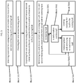
- the method includes initially selecting materials for the coining ball 40 which are harder than those of the first and second housing parts 210 and 211 and the sealing ball 22 (block 501), providing the first and second housing parts 210 and 211 to have respective structures as described above (block 502) and disposing the first and second housing parts 210 and 211 such that the first and second minor surfaces 2102 and 2112 face each other in opposite directions and at a distance to define the metering hole 30 toward which the sealing ball 22 will be elastically biased by the elastic element 23 (block 503).
- the method further includes deforming the first and second corners 2103 and 2113 with the coining ball 40 as described above such that the first and second housing parts 210 and 211 cooperatively form the coined seat 50 described above at the metering hole 30 for seating and re-seating the sealing ball 22 (block 504).
- the deforming of block 504 of FIG. 5 may include increasing a load on the coining ball 40 as deformation begins (block 5041), determining whether the deformation is continuing (block 5042), continuing to increase the load of the coining ball 40 in an event the deformation is determined to be continuing in block 5042 (block 5043) and ceasing the loading of the coining ball 40 in an event continued deformation is determined to be negligible in block 5042 due to the coined seat 50 reaching a state of equilibrium which varies for different materials (block 5044).
- the deformation is realized as a localized plastic yielding of the materials of the first and second housing parts 210 and 211 whereby the materials effectively take the shape of the coining ball 40. During this deformation, the volume of the yielded materials flows around the coining ball 40 and thus forms the first and second sealing lips 52 and 54 (see FIGS. 3 and 4 ).
- FIGS. 6-9 an execution of the method of FIG. 5 is illustrated.
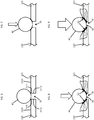
- FIG. 6 shows that the coining ball 40 is applied to the first and second housing parts 210 and 211 and the first and second corners 2103 and 2113 and
- FIG. 7 shows that the deformation of the first and second housing parts 210 and 211 commences with the coining ball 40 being increasingly loaded.
- FIG. 8 shows that the deformation of FIG. 7 continues as the loading of the coining ball 40 continues to be increased.
- FIG. 9 shows that further increases of the loading of the coining ball 40 do not result in further deformation beyond what is shown in FIG. 8 .
- FIG. 9 represents a late stage of the assembly process at which the loading is ceased and the sealing hole 60 is substantially fully formed in the metering hole 30.
- the PRV 20 described herein establishes clear and distinguishable pressure characteristics between crack, re-seat and flow point pressures.
- the PRV 20 also enables reduced valve sizes. This is a significant achievement especially with respect to aerospace qualified PRVs and is far away from any comparable relief valves available in the industry.
- the PRV 20 produces reliable metallic-to-metallic sealing (i.e., zero leakage/leakage well within acceptable limits) with clearly distinguishable pressure characteristics.
Landscapes
- Engineering & Computer Science (AREA)
- General Engineering & Computer Science (AREA)
- Mechanical Engineering (AREA)
- Physics & Mathematics (AREA)
- General Physics & Mathematics (AREA)
- Automation & Control Theory (AREA)
- Safety Valves (AREA)
- Check Valves (AREA)
Abstract
Description
- This application claims the benefit of Indian Application No.
201711040415, which was filed November 13, 2017 - The following description relates to actuators and, more specifically, to hydraulic locking actuators with pressure relief valves in which the valve seat is for metal-to-metal seating.
- Hydraulic locking actuators on aircraft often incorporate pressure relief valves (PRVs) to maintain system pressure within specified limits. This protects the actuator and actuator mounting brackets on aircraft nacelles from overload conditions due to over-pressurization. Typically, PRV design is based on metallic sealing in which a spring-loaded ball is held against a metallic seat.
- According to an aspect of the disclosure, a PRV is provided. The PRV includes a first housing part and a second housing part. The first housing part includes first major and minor surfaces and a first deformed corner at an intersection of the first major and minor surfaces. The second housing part includes second major and minor surfaces and a second deformed corner at an intersection of the second major and minor surfaces. The first and second housing parts are disposed with the first and second minor surfaces facing oppositely at a distance to define a metering hole and the first and second deformed corners are deformed by a coining ball to cooperatively form a coined seat at the metering hole for seating and re-seating a sealing ball. The first and second deformed corners have respective radii of curvatures resulting from deformation which are larger than that of the sealing ball.
- In accordance with additional or alternative embodiments, the coined seat includes a first curved edge and first corners at opposite ends of the first curved edge at the first housing part and the coined seat includes a second curved edge and second corners at opposite ends of the second curved edge at the second housing part.
- In accordance with additional or alternative embodiments, the respective radii of curvatures of the first and second curved edges are similar to that of the coining ball.
- In accordance with additional or alternative embodiments, the first corners include a first major surface corner which protrudes upwardly from a plane of the first major surface and a first minor surface corner which protrudes inwardly from a plane of the first minor surface and the second sealing lips include a second major surface corner which protrudes upwardly from a plane of the second major surface and a second minor surface corner which protrudes inwardly from a plane of the second minor surface.
- In accordance with additional or alternative embodiments, the first and second minor surface corners are disposed at the metering hole to define a sealing hole having a smaller diameter than the metering hole.
- In accordance with additional or alternative embodiments, the first and second minor surface corners are disposed at the metering hole to define a sealing hole having a diameter which is about 10% smaller than that of the metering hole.
- In accordance with additional or alternative embodiments, the first and second housing parts are up to 55 absolute hardness.
- According to another aspect of the disclosure, a pressure relief valve (PRV) is provided and includes first and second housing parts respectively including first and second major and minor surfaces and first and second deformed corners at respective intersections of the first and second major and minor surfaces, the first and second housing parts being disposed with the first and second minor surfaces facing oppositely at a distance to define a metering hole and a sealing ball which is elastically biased toward the metering hole. The first and second deformed corners are deformed by a coining ball having a larger diameter than the sealing ball to cooperatively form a coined seat at the metering hole for seating and re-seating the sealing ball.
- In accordance with additional or alternative embodiments, a third housing part fixed relative to the first and second housing parts and an elastic element coupled at opposite ends thereof to the sealing ball and the third housing part to elastically bias the sealing ball toward the metering hole.
- In accordance with additional or alternative embodiments, the coined seat includes a first curved edge and first corners at opposite ends of the first curved edge at the first housing part and the coined seat includes a second curved edge and second corners at opposite ends of the second curved edge at the second housing part.
- In accordance with additional or alternative embodiments, the first and second curved edges have respective radii of curvatures similar to that of the coining ball and greater than that of the sealing ball.
- In accordance with additional or alternative embodiments, the first corners include a first major surface corner which protrudes upwardly from a plane of the first major surface and a first minor surface corner which protrudes inwardly from a plane of the first minor surface and the second sealing lips include a second major surface corner which protrudes upwardly from a plane of the second major surface and a second minor surface corner which protrudes inwardly from a plane of the second minor surface.
- In accordance with additional or alternative embodiments, the first and second minor surface corners are disposed at the metering hole to define a sealing hole having a smaller diameter than the metering hole.
- In accordance with additional or alternative embodiments, the first and second minor surface corners are disposed at the metering hole to define a sealing hole having a diameter which is about 10% smaller than that of the metering hole.
- In accordance with additional or alternative embodiments, the first and second housing parts and the sealing ball have similar absolute hardness and are less hard than the coining ball.
- In accordance with additional or alternative embodiments, the first and second housing parts are up to 55 absolute hardness, the sealing ball has 40-70 absolute hardness and the first and second housing parts and the sealing ball are less hard than the coining ball.
- In accordance with additional or alternative embodiments, a hydraulic locking actuator is provided and includes an actuator element, an inlet by which fluid is provided to the actuator element and the PRV disposed along the inlet to prevent an overpressure condition at the actuator element.
- According to yet another aspect of the disclosure, a method of assembling a pressure relief valve is provided and includes providing first and second housing parts respectively including first and second major and minor surfaces and first and second corners at respective intersections of the first and second major and minor surfaces, disposing the first and second housing parts such that the first and second minor surfaces face oppositely at a distance to define a metering hole toward which a sealing ball will be elastically biased and deforming the first and second corners with a coining ball having a larger diameter than the sealing ball such that the first and second housing parts cooperatively form a coined seat at the metering hole for seating and re-seating the sealing ball.
- In accordance with additional or alternative embodiments, the method further includes selecting materials for the coining ball which are harder than those of the first and second housing parts and the sealing ball.
- In accordance with additional or alternative embodiments, the deforming includes increasing a load on the coining ball until further deformation is negligible.
- These and other advantages and features will become more apparent from the following description taken in conjunction with the drawings.
- The subject matter, which is regarded as the disclosure, is particularly pointed out and distinctly claimed in the claims at the conclusion of the specification. The foregoing and other features and advantages of the disclosure are apparent from the following detailed description taken in conjunction with the accompanying drawings in which:
-
FIG. 1 is a schematic illustration of a hydraulic locking actuator in accordance with embodiments; -
FIG. 2A is a side view of a pressure relief valve of the hydraulic locking actuator ofFIG. 1 with a seated sealing ball in accordance with embodiments; -
FIG. 2B is a side view of a pressure relief valve of the hydraulic locking actuator ofFIG. 1 with an unseated sealing ball in accordance with embodiments; -
FIG. 3 is an enlarged side view of a portion of the pressure relief valve ofFIG. 2A in accordance with embodiments; -
FIG. 4 is an enlarged side view of a portion of the pressure relief valve ofFIG. 2A in accordance with embodiments; -
FIG. 5 is a flow diagram illustrating a method of assembling a pressure relief valve in accordance with embodiments; -
FIG. 6 is an illustration of an early stage of the method ofFIG. 5 in accordance with embodiments; -
FIG. 7 is an illustration of an intermediate stage of the method ofFIG. 5 in accordance with embodiments; -
FIG. 8 is an illustration of an intermediate stage of the method ofFIG. 5 in accordance with embodiments; and -
FIG. 9 is an illustration of a late stage of the method ofFIG. 5 in accordance with embodiments. - These and other advantages and features will become more apparent from the following description taken in conjunction with the drawings.
- PRVs in aircraft applications are sized for cracking, flow point and re-seat pressures. Since the actuators to which the PRVs are often connected are hydraulic locking actuators, there exists a leakage requirement for the PRVs at a re-seat pressure so that the hydraulic lock actuators do not descend in the loaded condition, due to leakage. This leakage requirement may be, for example, less than or equal to 3 drops per minute.
- In conventional PRVs, the coined-seat is formed with a coining ball that is substantially the same size as the PRV assembly ball. This leads to substantially excessive leakage of about 7 to 8 drops per 10 seconds at the re-seat pressure as well as unreliable re-seat operations due to the excessive leakage (i.e., a continuous or nearly continuous stream of fluid at pressures less than 1/3rd of the re-seat pressure can prevent reliable re-seating).
- Thus, as an improvement in some PRVs, the coining ball diameter was increased so as to be slightly larger than the assembly or PRV ball diameter. This still did not result in improved leakage prevention, however, and continued excessive and uncontrolled leakage were observed on PRVs.
- As will be described below, a coined seat is provided. The coined seat evolved from the notion that a load exists at which a coined seat is produced in a housing and, based on iteratively increasing load applications, the yielding (plastic deformation) of the edge of the housing occurs. That is, as loads are increased during coining operations, localized plastic yielding occurs on the edge of the housing being coined. The resulting deformation leads to a deformed edge that takes the shape of the coining ball (e.g., circular) because the volume of the yielded material effectively flows around the coining ball in a free zone (i.e., outwardly and inwardly with respect to the metering hole). The material which flows inwards with respect to the metering hole forms the seat for the sealing ball upon assembly and is referred to as a coined seat. The coined-seat attains an equilibrium state after a certain load level is reached, beyond which further seat deformation is negligible. This load level is referred to as the "coining load" to form the coined seat.
- With reference to
FIG. 1 , ahydraulic locking actuator 10 is provided for use in various applications such as, but not limited to, aircraft and engine nacelle actuation. Thehydraulic actuator 10 includes anactuator element 11, aninlet 12 by which fluid is provided to theactuator element 11 and aPRV 20. ThePRV 20 is disposed along theinlet 12 and is configured to prevent an overpressure condition at theactuator element 11. - With continued reference to
FIG. 1 and with additional reference toFIGS. 2A, 2B ,3 and 4 , thePRV 20 includes ahousing 21, a sealingball 22 and anelastic element 23. At least initially, thehousing 21 includes afirst housing part 210, asecond housing part 211 and athird housing part 212 which is fixed relative to the first andsecond housing parts first housing part 210 includes a firstmajor surface 2101, a firstminor surface 2102 and a first corner 2103 (seeFIG. 6 ) at an intersection of the first major andminor surfaces second housing part 211 includes a secondmajor surface 2111, a secondminor surface 2112 and a second corner 2113 (seeFIG. 6 ) at an intersection of the second major andminor surfaces - As shown in
FIGS. 1, 2A, 2B ,3 and 4 , the first andsecond housing parts minor surfaces metering hole 30. The respective planes P1major and P2major of the first and secondmajor surfaces minor surfaces metering hole 30. Theelastic element 23 may be provided as a spring and is coupled at a first end thereof to thethird housing part 212 and at a second end thereof to the sealingball 22. Theelastic element 23 thus elastically biases the sealingball 22 toward themetering hole 30. - As shown in
FIGS. 2A, 2B ,3 and 4 , the first andsecond corners ball 40 being applied to the first andsecond corners FIG. 2A ) of the coiningball 40 may be larger than the diameter DS (seeFIG. 2B ) of the sealingball 22. As such, the first andsecond corners 2103 and 2113 (having been deformed by the loading of the coining ball 40) cooperatively form a coinedseat 50 at themetering hole 30. In accordance with embodiments, the diameter DC of the coiningball 40 may be about 20% larger than the diameter DS of the sealingball 22. - In accordance with embodiments, the first and
second housing parts ball 22 may have a similar absolute hardness and may be less hard than the coiningball 40. The first andsecond housing parts ball 22 may be formed from stainless and/or hardened steel or other similar materials (but may also be formed from dissimilar materials during assembly processes in particular to prevent galvanic corrosion). In accordance with further embodiments, the first andsecond housing parts ball 22 may have 40-70 absolute hardness. - The coined
seat 50 is disposed and configured to provide for seating and re-seating the sealingball 22. That is, as fluid pressure acting on the sealingball 22 in the seated condition increases, the sealingball 22 moves out of the seated condition in opposition to the elastic bias of the elastic element 23 (seeFIG. 2B ). Conversely, as fluid pressure decreases, the sealingball 22 is urged by the bias of theelastic element 23 back toward and into the re-seating condition (seeFIG. 2A ). - In accordance with embodiments, the structure and characteristics of the coined
seat 50 are such that thePRV 20 exhibits no leakage (or leakage well within acceptable limits) with the sealingball 22 in the seated or re-seated conditions. - With continued reference to
FIGS. 3 and 4 , the coinedseat 50 includes a first curved edge 51 (or a first special surface) andfirst corners 52, including a firstmajor surface corner 520 and a firstminor surface corner 521, at opposite ends of the firstcurved edge 51 at thefirst housing part 210 as well as a second curved edge 53 (or a second special surface) andsecond corners 54, including a secondmajor surface corner 540 and a secondminor surface corner 541, at opposite ends of the secondcurved edge 53 at thesecond housing part 211. The first and secondcurved edges ball 40. The sealingball 22 has a radius of curvature which is less than those of the first and secondcurved edges ball 40. This results in the sealingball 22 tending to engage with the first and secondminor surface corners elastic element 23. - As noted above, the
first corners 52 include the firstmajor surface corner 520 and the firstminor surface corner 521. The firstmajor surface corner 520 protrudes upwardly from the plane P1major and the firstminor surface corner 521 protrudes inwardly into themetering hole 30 from the plane P1minor. Thesecond corners 54 include a secondmajor surface corner 540 and a secondminor surface corner 541. The secondmajor surface corner 540 protrudes upwardly from the plane P2major and the secondminor surface corner 541 protrudes inwardly into themetering hole 30 from the plane P2minor. The first and secondminor surface corners major surface corners - In any case, the first and second
minor surface corners metering hole 30 to define a sealinghole 60. A diameter DS of the sealinghole 60 is measured as a horizontal distance between respective interior tips of the first and secondminor surface corners metering hole 30 measured as a horizontal distance between the first and secondminor surfaces hole 60 may be about 10% smaller than the diameter DM of the metering hole 30 (e.g., the diameter DM of themetering hole 30 may be about 3mm and the diameter DS of the sealinghole 60 may be about 2.7 mm). - With reference to
FIGS. 5 and6-9 , a method of assembling a PRV, such asPRV 20, is provided. - As shown in
FIG. 5 , the method includes initially selecting materials for the coiningball 40 which are harder than those of the first andsecond housing parts second housing parts second housing parts minor surfaces metering hole 30 toward which the sealingball 22 will be elastically biased by the elastic element 23 (block 503). The method further includes deforming the first andsecond corners ball 40 as described above such that the first andsecond housing parts seat 50 described above at themetering hole 30 for seating and re-seating the sealing ball 22 (block 504). - In accordance with embodiments, the deforming of
block 504 ofFIG. 5 may include increasing a load on the coiningball 40 as deformation begins (block 5041), determining whether the deformation is continuing (block 5042), continuing to increase the load of the coiningball 40 in an event the deformation is determined to be continuing in block 5042 (block 5043) and ceasing the loading of the coiningball 40 in an event continued deformation is determined to be negligible in block 5042 due to the coinedseat 50 reaching a state of equilibrium which varies for different materials (block 5044). The deformation is realized as a localized plastic yielding of the materials of the first andsecond housing parts ball 40. During this deformation, the volume of the yielded materials flows around the coiningball 40 and thus forms the first and second sealinglips 52 and 54 (seeFIGS. 3 and 4 ). - As shown in
FIGS. 6-9 , an execution of the method ofFIG. 5 is illustrated.FIG. 6 shows that the coiningball 40 is applied to the first andsecond housing parts second corners FIG. 7 shows that the deformation of the first andsecond housing parts ball 40 being increasingly loaded.FIG. 8 shows that the deformation ofFIG. 7 continues as the loading of the coiningball 40 continues to be increased.FIG. 9 , however, shows that further increases of the loading of the coiningball 40 do not result in further deformation beyond what is shown inFIG. 8 . Thus,FIG. 9 represents a late stage of the assembly process at which the loading is ceased and the sealinghole 60 is substantially fully formed in themetering hole 30. - The
PRV 20 described herein establishes clear and distinguishable pressure characteristics between crack, re-seat and flow point pressures. ThePRV 20 also enables reduced valve sizes. This is a significant achievement especially with respect to aerospace qualified PRVs and is far away from any comparable relief valves available in the industry. In addition, thePRV 20 produces reliable metallic-to-metallic sealing (i.e., zero leakage/leakage well within acceptable limits) with clearly distinguishable pressure characteristics. - While the disclosure is provided in detail in connection with only a limited number of embodiments, it should be readily understood that the disclosure is not limited to such disclosed embodiments. Rather, the disclosure can be modified to incorporate any number of variations, alterations, substitutions or equivalent arrangements not heretofore described, but which are commensurate with the scope of the invention as defined by the claims. Additionally, while various embodiments of the disclosure have been described, it is to be understood that the exemplary embodiment(s) may include only some of the described exemplary aspects. Accordingly, the disclosure is not to be seen as limited by the foregoing description, but is only limited by the scope of the appended claims.
Claims (15)
- A pressure relief valve (PRV), comprising:a first housing part (210) comprising first major (2101) and minor (2102) surfaces and a first deformed corner (2103) at an intersection of the first major and minor surfaces; anda second housing part (211) comprising second major (2111) and minor (2112) surfaces and a second deformed corner (2113) at an intersection of the second major and minor surfaces,the first and second housing parts being disposed with the first and second minor surfaces facing oppositely at a distance to define a metering hole (30),the first and second deformed corners being deformed by a coining ball (40) to cooperatively form a coined seat (50) at the metering hole for seating and re-seating a sealing ball (22), andthe first and second deformed corners having respective radii of curvatures resulting from deformation which are larger than that of the sealing ball.
- The PRV according to claim 1, wherein:at the first housing part, the coined seat (50) comprises a first curved edge (51) and first corners (52) at opposite ends of the first curved edge, andat the second housing part, the coined seat comprises a second curved edge (53) and second corners (54) at opposite ends of the second curved edge.
- The PRV according to claim 2, wherein the respective radii of curvatures of the first and second curved edges are similar to that of the coining ball.
- The PRV according to claim 2 or 3, wherein:the first corners comprise a first major surface corner (520) which protrudes upwardly from a plane of the first major surface and a first minor surface corner (521) which protrudes inwardly from a plane of the first minor surface, andthe second corners comprise a second major surface corner (540) which protrudes upwardly from a plane of the second major surface and a second minor surface corner (541) which protrudes inwardly from a plane of the second minor surface.
- The PRV according to claim 4, wherein the first and second minor surface corners are disposed at the metering hole (30) to define a sealing hole (60) having a smaller diameter than the metering hole.
- The PRV according to claim 4, wherein the first and second minor surface corners are disposed at the metering hole to define a sealing hole having a diameter which is about 10% smaller than that of the metering hole.
- The PRV according to claim 1, wherein the first and second housing parts are up to 55 absolute hardness.
- A pressure relief valve (PRV), comprising:first and second housing parts (210,211) respectively comprising first and second major and minor surfaces (2101,2111,2102,2112) and first and second deformed corners (2103,2113) at respective intersections of the first and second major and minor surfaces,the first and second housing parts being disposed with the first and second minor surfaces facing oppositely at a distance to define a metering hole (30); anda sealing ball (22) which is elastically biased toward the metering hole,the first and second deformed corners being deformed by a coining ball (40) having a larger diameter than the sealing ball to cooperatively form a coined seat (50) at the metering hole for seating and re-seating the sealing ball.
- The PRV according to claim 8, further comprising:a third housing part (212) fixed relative to the first and second housing parts; andan elastic element (23) coupled at opposite ends thereof to the sealing ball and the third housing part to elastically bias the sealing ball toward the metering hole.
- The PRV according to claim 8, wherein:at the first housing part, the coined seat comprises a first curved edge (51) and first corners (52) at opposite ends of the first curved edge, andat the second housing part, the coined seat comprises a second curved edge (53) and second corners (54) at opposite ends of the second curved edge.
- The PRV according to claim 10, wherein the first and second curved edges have respective radii of curvatures similar to that of the coining ball and greater than that of the sealing ball.
- The PRV according to claim 10, wherein:the first corners comprise a first major surface corner (520) which protrudes upwardly from a plane of the first major surface and a first minor surface corner (521) which protrudes inwardly from a plane of the first minor surface, andthe second corners comprise a second major surface corner (540) which protrudes upwardly from a plane of the second major surface and a second minor surface corner (541) which protrudes inwardly from a plane of the second minor surface.
- The PRV according to claim 12, wherein the first and second minor surface corners are disposed at the metering hole (30) to define a sealing hole (60) having a smaller diameter than the metering hole.
- The PRV according to claim 12, wherein the first and second minor surface corners are disposed at the metering hole to define a sealing hole having a diameter which is about 10% smaller than that of the metering hole.
- The PRV according to claim 8, wherein the first and second housing parts and the sealing ball have similar absolute hardness and are less hard than the coining ball.
Applications Claiming Priority (1)
| Application Number | Priority Date | Filing Date | Title |
|---|---|---|---|
| IN201711040415 | 2017-11-13 |
Publications (2)
| Publication Number | Publication Date |
|---|---|
| EP3483489A1 true EP3483489A1 (en) | 2019-05-15 |
| EP3483489B1 EP3483489B1 (en) | 2024-04-17 |
Family
ID=64308641
Family Applications (1)
| Application Number | Title | Priority Date | Filing Date |
|---|---|---|---|
| EP18205973.3A Active EP3483489B1 (en) | 2017-11-13 | 2018-11-13 | Coined seat for metal-to-metal seating |
Country Status (4)
| Country | Link |
|---|---|
| US (1) | US11204103B2 (en) |
| EP (1) | EP3483489B1 (en) |
| BR (1) | BR102018073264A2 (en) |
| CA (1) | CA3024058A1 (en) |
Cited By (2)
| Publication number | Priority date | Publication date | Assignee | Title |
|---|---|---|---|---|
| WO2022221841A1 (en) | 2021-04-14 | 2022-10-20 | Dresser, Llc | Improving safety valves for use at extremely high temperatures |
| CN117662987A (en) * | 2023-12-13 | 2024-03-08 | 北京天玛智控科技股份有限公司 | Hydrogen refueling port and vehicle |
Families Citing this family (2)
| Publication number | Priority date | Publication date | Assignee | Title |
|---|---|---|---|---|
| DE102021101831A1 (en) * | 2021-01-27 | 2022-07-28 | Dionex Softron Gmbh | valve assembly |
| EP4528138A1 (en) | 2023-09-19 | 2025-03-26 | Microtecnica S.r.l. | Valve |
Citations (6)
| Publication number | Priority date | Publication date | Assignee | Title |
|---|---|---|---|---|
| US2697953A (en) * | 1951-02-05 | 1954-12-28 | Aeroprojects Inc | Dimpling |
| DE19509776A1 (en) * | 1995-03-17 | 1996-09-19 | Rexroth Mannesmann Gmbh | Direction-controlled pressure control valve, esp. for pressure redn. and relay valves |
| US7832661B2 (en) * | 2003-09-29 | 2010-11-16 | Continental Automotive Systems Us, Inc. | Injector seat that includes a coined seal band with radius |
| JP2011154957A (en) * | 2010-01-28 | 2011-08-11 | Fuji Hatsujo Kk | Sealing plate for battery, method and metal mold for manufacturing the same |
| US8382454B2 (en) * | 2007-10-23 | 2013-02-26 | Shimadzu Corporation | Check valve, infusion device using the same, and method of manufacturing the same |
| US9797519B2 (en) * | 2007-01-10 | 2017-10-24 | Fritz Gyger Ag | Micro-valve |
Family Cites Families (5)
| Publication number | Priority date | Publication date | Assignee | Title |
|---|---|---|---|---|
| US3035610A (en) * | 1959-09-10 | 1962-05-22 | Oliver Corp | Control valve for hydraulic actuator |
| US5107890A (en) | 1990-05-03 | 1992-04-28 | Huron Products Industries, Inc. | Ball check valve |
| US6840270B2 (en) | 2002-10-09 | 2005-01-11 | Visteon Global Technologies, Inc. | Low deviation pressure relief valve for fuel pumps |
| DE10360706A1 (en) * | 2003-12-19 | 2005-07-14 | Aweco Appliance Systems Gmbh & Co. Kg | Valve and method for manufacturing a valve |
| JP2005201303A (en) | 2004-01-13 | 2005-07-28 | Toyota Industries Corp | Valve device manufacturing method |
-
2018
- 2018-09-05 US US16/122,469 patent/US11204103B2/en active Active
- 2018-11-12 BR BR102018073264-1A patent/BR102018073264A2/en not_active Application Discontinuation
- 2018-11-13 EP EP18205973.3A patent/EP3483489B1/en active Active
- 2018-11-13 CA CA3024058A patent/CA3024058A1/en active Pending
Patent Citations (6)
| Publication number | Priority date | Publication date | Assignee | Title |
|---|---|---|---|---|
| US2697953A (en) * | 1951-02-05 | 1954-12-28 | Aeroprojects Inc | Dimpling |
| DE19509776A1 (en) * | 1995-03-17 | 1996-09-19 | Rexroth Mannesmann Gmbh | Direction-controlled pressure control valve, esp. for pressure redn. and relay valves |
| US7832661B2 (en) * | 2003-09-29 | 2010-11-16 | Continental Automotive Systems Us, Inc. | Injector seat that includes a coined seal band with radius |
| US9797519B2 (en) * | 2007-01-10 | 2017-10-24 | Fritz Gyger Ag | Micro-valve |
| US8382454B2 (en) * | 2007-10-23 | 2013-02-26 | Shimadzu Corporation | Check valve, infusion device using the same, and method of manufacturing the same |
| JP2011154957A (en) * | 2010-01-28 | 2011-08-11 | Fuji Hatsujo Kk | Sealing plate for battery, method and metal mold for manufacturing the same |
Cited By (4)
| Publication number | Priority date | Publication date | Assignee | Title |
|---|---|---|---|---|
| WO2022221841A1 (en) | 2021-04-14 | 2022-10-20 | Dresser, Llc | Improving safety valves for use at extremely high temperatures |
| CN117043499A (en) * | 2021-04-14 | 2023-11-10 | 德莱赛有限责任公司 | Improving safety valves for use at extremely high temperatures |
| EP4323675A4 (en) * | 2021-04-14 | 2025-02-26 | Dresser, LLC | Improving safety valves for use at extremely high temperatures |
| CN117662987A (en) * | 2023-12-13 | 2024-03-08 | 北京天玛智控科技股份有限公司 | Hydrogen refueling port and vehicle |
Also Published As
| Publication number | Publication date |
|---|---|
| EP3483489B1 (en) | 2024-04-17 |
| BR102018073264A2 (en) | 2019-06-04 |
| US20190145537A1 (en) | 2019-05-16 |
| US11204103B2 (en) | 2021-12-21 |
| CA3024058A1 (en) | 2019-05-13 |
Similar Documents
| Publication | Publication Date | Title |
|---|---|---|
| EP3483489B1 (en) | Coined seat for metal-to-metal seating | |
| CN112166270A (en) | Valves and Seats with Seals | |
| KR102392776B1 (en) | Valve device | |
| US7591450B1 (en) | Valve body and seal assembly | |
| KR20080001627A (en) | Flow control valve | |
| EP3468323B1 (en) | Perimeter seal | |
| US20160131285A1 (en) | Piping joint structure | |
| AU2022265430B2 (en) | Gasket apparatus and method of forming | |
| US20160153572A1 (en) | Non chattering pressure relief valve | |
| EP3494335B1 (en) | Seal, assembly, and retention method | |
| US20140264134A1 (en) | Valve seal assembly with relief volume | |
| EP3647605B1 (en) | Accumulator | |
| US20040222593A1 (en) | O-ring forming sealing washer | |
| EP1500855A1 (en) | Pressure control valve | |
| US20160251910A1 (en) | Riser bearing with high shape factor | |
| EP3012017A1 (en) | Lining structure | |
| EP3236113B1 (en) | Improvements in or relating to metal-to-metal sealing | |
| US6361052B1 (en) | Seal for preventing leakage of fluids between irregular areas on mating surfaces | |
| ES2682036T3 (en) | Apparatus for determining and verifying a set point in a valve assembly | |
| WO2012092166A1 (en) | Hydraulic flange connection | |
| EP2682618B1 (en) | Integral spherical bearing and corresponding mounting method | |
| EP1925865A1 (en) | Metal stem seal | |
| JP7762051B2 (en) | non-return valve | |
| US9416880B2 (en) | Rotary metering valve assembly and method of modifying contact surface for reducing gauge wringing | |
| US20250172215A1 (en) | Check valve |
Legal Events
| Date | Code | Title | Description |
|---|---|---|---|
| PUAI | Public reference made under article 153(3) epc to a published international application that has entered the european phase |
Free format text: ORIGINAL CODE: 0009012 |
|
| STAA | Information on the status of an ep patent application or granted ep patent |
Free format text: STATUS: THE APPLICATION HAS BEEN PUBLISHED |
|
| AK | Designated contracting states |
Kind code of ref document: A1 Designated state(s): AL AT BE BG CH CY CZ DE DK EE ES FI FR GB GR HR HU IE IS IT LI LT LU LV MC MK MT NL NO PL PT RO RS SE SI SK SM TR |
|
| AX | Request for extension of the european patent |
Extension state: BA ME |
|
| STAA | Information on the status of an ep patent application or granted ep patent |
Free format text: STATUS: REQUEST FOR EXAMINATION WAS MADE |
|
| 17P | Request for examination filed |
Effective date: 20191115 |
|
| RBV | Designated contracting states (corrected) |
Designated state(s): AL AT BE BG CH CY CZ DE DK EE ES FI FR GB GR HR HU IE IS IT LI LT LU LV MC MK MT NL NO PL PT RO RS SE SI SK SM TR |
|
| STAA | Information on the status of an ep patent application or granted ep patent |
Free format text: STATUS: EXAMINATION IS IN PROGRESS |
|
| 17Q | First examination report despatched |
Effective date: 20201029 |
|
| GRAP | Despatch of communication of intention to grant a patent |
Free format text: ORIGINAL CODE: EPIDOSNIGR1 |
|
| STAA | Information on the status of an ep patent application or granted ep patent |
Free format text: STATUS: GRANT OF PATENT IS INTENDED |
|
| INTG | Intention to grant announced |
Effective date: 20231122 |
|
| GRAS | Grant fee paid |
Free format text: ORIGINAL CODE: EPIDOSNIGR3 |
|
| GRAA | (expected) grant |
Free format text: ORIGINAL CODE: 0009210 |
|
| STAA | Information on the status of an ep patent application or granted ep patent |
Free format text: STATUS: THE PATENT HAS BEEN GRANTED |
|
| AK | Designated contracting states |
Kind code of ref document: B1 Designated state(s): AL AT BE BG CH CY CZ DE DK EE ES FI FR GB GR HR HU IE IS IT LI LT LU LV MC MK MT NL NO PL PT RO RS SE SI SK SM TR |
|
| REG | Reference to a national code |
Ref country code: GB Ref legal event code: FG4D |
|
| REG | Reference to a national code |
Ref country code: CH Ref legal event code: EP |
|
| REG | Reference to a national code |
Ref country code: DE Ref legal event code: R096 Ref document number: 602018068124 Country of ref document: DE |
|
| REG | Reference to a national code |
Ref country code: IE Ref legal event code: FG4D |
|
| REG | Reference to a national code |
Ref country code: LT Ref legal event code: MG9D |
|
| REG | Reference to a national code |
Ref country code: NL Ref legal event code: MP Effective date: 20240417 |
|
| REG | Reference to a national code |
Ref country code: AT Ref legal event code: MK05 Ref document number: 1677545 Country of ref document: AT Kind code of ref document: T Effective date: 20240417 |
|
| PG25 | Lapsed in a contracting state [announced via postgrant information from national office to epo] |
Ref country code: NL Free format text: LAPSE BECAUSE OF FAILURE TO SUBMIT A TRANSLATION OF THE DESCRIPTION OR TO PAY THE FEE WITHIN THE PRESCRIBED TIME-LIMIT Effective date: 20240417 |
|
| PG25 | Lapsed in a contracting state [announced via postgrant information from national office to epo] |
Ref country code: NL Free format text: LAPSE BECAUSE OF FAILURE TO SUBMIT A TRANSLATION OF THE DESCRIPTION OR TO PAY THE FEE WITHIN THE PRESCRIBED TIME-LIMIT Effective date: 20240417 |
|
| PG25 | Lapsed in a contracting state [announced via postgrant information from national office to epo] |
Ref country code: IS Free format text: LAPSE BECAUSE OF FAILURE TO SUBMIT A TRANSLATION OF THE DESCRIPTION OR TO PAY THE FEE WITHIN THE PRESCRIBED TIME-LIMIT Effective date: 20240817 |
|
| PG25 | Lapsed in a contracting state [announced via postgrant information from national office to epo] |
Ref country code: BG Free format text: LAPSE BECAUSE OF FAILURE TO SUBMIT A TRANSLATION OF THE DESCRIPTION OR TO PAY THE FEE WITHIN THE PRESCRIBED TIME-LIMIT Effective date: 20240417 |
|
| PG25 | Lapsed in a contracting state [announced via postgrant information from national office to epo] |
Ref country code: HR Free format text: LAPSE BECAUSE OF FAILURE TO SUBMIT A TRANSLATION OF THE DESCRIPTION OR TO PAY THE FEE WITHIN THE PRESCRIBED TIME-LIMIT Effective date: 20240417 Ref country code: FI Free format text: LAPSE BECAUSE OF FAILURE TO SUBMIT A TRANSLATION OF THE DESCRIPTION OR TO PAY THE FEE WITHIN THE PRESCRIBED TIME-LIMIT Effective date: 20240417 |
|
| PG25 | Lapsed in a contracting state [announced via postgrant information from national office to epo] |
Ref country code: GR Free format text: LAPSE BECAUSE OF FAILURE TO SUBMIT A TRANSLATION OF THE DESCRIPTION OR TO PAY THE FEE WITHIN THE PRESCRIBED TIME-LIMIT Effective date: 20240718 |
|
| PG25 | Lapsed in a contracting state [announced via postgrant information from national office to epo] |
Ref country code: PT Free format text: LAPSE BECAUSE OF FAILURE TO SUBMIT A TRANSLATION OF THE DESCRIPTION OR TO PAY THE FEE WITHIN THE PRESCRIBED TIME-LIMIT Effective date: 20240819 |
|
| PG25 | Lapsed in a contracting state [announced via postgrant information from national office to epo] |
Ref country code: ES Free format text: LAPSE BECAUSE OF FAILURE TO SUBMIT A TRANSLATION OF THE DESCRIPTION OR TO PAY THE FEE WITHIN THE PRESCRIBED TIME-LIMIT Effective date: 20240417 |
|
| PG25 | Lapsed in a contracting state [announced via postgrant information from national office to epo] |
Ref country code: AT Free format text: LAPSE BECAUSE OF FAILURE TO SUBMIT A TRANSLATION OF THE DESCRIPTION OR TO PAY THE FEE WITHIN THE PRESCRIBED TIME-LIMIT Effective date: 20240417 |
|
| PG25 | Lapsed in a contracting state [announced via postgrant information from national office to epo] |
Ref country code: PL Free format text: LAPSE BECAUSE OF FAILURE TO SUBMIT A TRANSLATION OF THE DESCRIPTION OR TO PAY THE FEE WITHIN THE PRESCRIBED TIME-LIMIT Effective date: 20240417 |
|
| PG25 | Lapsed in a contracting state [announced via postgrant information from national office to epo] |
Ref country code: LV Free format text: LAPSE BECAUSE OF FAILURE TO SUBMIT A TRANSLATION OF THE DESCRIPTION OR TO PAY THE FEE WITHIN THE PRESCRIBED TIME-LIMIT Effective date: 20240417 |
|
| PG25 | Lapsed in a contracting state [announced via postgrant information from national office to epo] |
Ref country code: PT Free format text: LAPSE BECAUSE OF FAILURE TO SUBMIT A TRANSLATION OF THE DESCRIPTION OR TO PAY THE FEE WITHIN THE PRESCRIBED TIME-LIMIT Effective date: 20240819 Ref country code: PL Free format text: LAPSE BECAUSE OF FAILURE TO SUBMIT A TRANSLATION OF THE DESCRIPTION OR TO PAY THE FEE WITHIN THE PRESCRIBED TIME-LIMIT Effective date: 20240417 Ref country code: NO Free format text: LAPSE BECAUSE OF FAILURE TO SUBMIT A TRANSLATION OF THE DESCRIPTION OR TO PAY THE FEE WITHIN THE PRESCRIBED TIME-LIMIT Effective date: 20240717 Ref country code: LV Free format text: LAPSE BECAUSE OF FAILURE TO SUBMIT A TRANSLATION OF THE DESCRIPTION OR TO PAY THE FEE WITHIN THE PRESCRIBED TIME-LIMIT Effective date: 20240417 Ref country code: IS Free format text: LAPSE BECAUSE OF FAILURE TO SUBMIT A TRANSLATION OF THE DESCRIPTION OR TO PAY THE FEE WITHIN THE PRESCRIBED TIME-LIMIT Effective date: 20240817 Ref country code: HR Free format text: LAPSE BECAUSE OF FAILURE TO SUBMIT A TRANSLATION OF THE DESCRIPTION OR TO PAY THE FEE WITHIN THE PRESCRIBED TIME-LIMIT Effective date: 20240417 Ref country code: GR Free format text: LAPSE BECAUSE OF FAILURE TO SUBMIT A TRANSLATION OF THE DESCRIPTION OR TO PAY THE FEE WITHIN THE PRESCRIBED TIME-LIMIT Effective date: 20240718 Ref country code: FI Free format text: LAPSE BECAUSE OF FAILURE TO SUBMIT A TRANSLATION OF THE DESCRIPTION OR TO PAY THE FEE WITHIN THE PRESCRIBED TIME-LIMIT Effective date: 20240417 Ref country code: ES Free format text: LAPSE BECAUSE OF FAILURE TO SUBMIT A TRANSLATION OF THE DESCRIPTION OR TO PAY THE FEE WITHIN THE PRESCRIBED TIME-LIMIT Effective date: 20240417 Ref country code: BG Free format text: LAPSE BECAUSE OF FAILURE TO SUBMIT A TRANSLATION OF THE DESCRIPTION OR TO PAY THE FEE WITHIN THE PRESCRIBED TIME-LIMIT Effective date: 20240417 Ref country code: AT Free format text: LAPSE BECAUSE OF FAILURE TO SUBMIT A TRANSLATION OF THE DESCRIPTION OR TO PAY THE FEE WITHIN THE PRESCRIBED TIME-LIMIT Effective date: 20240417 Ref country code: RS Free format text: LAPSE BECAUSE OF FAILURE TO SUBMIT A TRANSLATION OF THE DESCRIPTION OR TO PAY THE FEE WITHIN THE PRESCRIBED TIME-LIMIT Effective date: 20240717 |
|
| PG25 | Lapsed in a contracting state [announced via postgrant information from national office to epo] |
Ref country code: DK Free format text: LAPSE BECAUSE OF FAILURE TO SUBMIT A TRANSLATION OF THE DESCRIPTION OR TO PAY THE FEE WITHIN THE PRESCRIBED TIME-LIMIT Effective date: 20240417 |
|
| REG | Reference to a national code |
Ref country code: DE Ref legal event code: R097 Ref document number: 602018068124 Country of ref document: DE |
|
| PG25 | Lapsed in a contracting state [announced via postgrant information from national office to epo] |
Ref country code: EE Free format text: LAPSE BECAUSE OF FAILURE TO SUBMIT A TRANSLATION OF THE DESCRIPTION OR TO PAY THE FEE WITHIN THE PRESCRIBED TIME-LIMIT Effective date: 20240417 |
|
| PG25 | Lapsed in a contracting state [announced via postgrant information from national office to epo] |
Ref country code: CZ Free format text: LAPSE BECAUSE OF FAILURE TO SUBMIT A TRANSLATION OF THE DESCRIPTION OR TO PAY THE FEE WITHIN THE PRESCRIBED TIME-LIMIT Effective date: 20240417 |
|
| PG25 | Lapsed in a contracting state [announced via postgrant information from national office to epo] |
Ref country code: SK Free format text: LAPSE BECAUSE OF FAILURE TO SUBMIT A TRANSLATION OF THE DESCRIPTION OR TO PAY THE FEE WITHIN THE PRESCRIBED TIME-LIMIT Effective date: 20240417 Ref country code: RO Free format text: LAPSE BECAUSE OF FAILURE TO SUBMIT A TRANSLATION OF THE DESCRIPTION OR TO PAY THE FEE WITHIN THE PRESCRIBED TIME-LIMIT Effective date: 20240417 |
|
| PG25 | Lapsed in a contracting state [announced via postgrant information from national office to epo] |
Ref country code: SM Free format text: LAPSE BECAUSE OF FAILURE TO SUBMIT A TRANSLATION OF THE DESCRIPTION OR TO PAY THE FEE WITHIN THE PRESCRIBED TIME-LIMIT Effective date: 20240417 |
|
| PG25 | Lapsed in a contracting state [announced via postgrant information from national office to epo] |
Ref country code: SM Free format text: LAPSE BECAUSE OF FAILURE TO SUBMIT A TRANSLATION OF THE DESCRIPTION OR TO PAY THE FEE WITHIN THE PRESCRIBED TIME-LIMIT Effective date: 20240417 Ref country code: SK Free format text: LAPSE BECAUSE OF FAILURE TO SUBMIT A TRANSLATION OF THE DESCRIPTION OR TO PAY THE FEE WITHIN THE PRESCRIBED TIME-LIMIT Effective date: 20240417 Ref country code: RO Free format text: LAPSE BECAUSE OF FAILURE TO SUBMIT A TRANSLATION OF THE DESCRIPTION OR TO PAY THE FEE WITHIN THE PRESCRIBED TIME-LIMIT Effective date: 20240417 Ref country code: EE Free format text: LAPSE BECAUSE OF FAILURE TO SUBMIT A TRANSLATION OF THE DESCRIPTION OR TO PAY THE FEE WITHIN THE PRESCRIBED TIME-LIMIT Effective date: 20240417 Ref country code: DK Free format text: LAPSE BECAUSE OF FAILURE TO SUBMIT A TRANSLATION OF THE DESCRIPTION OR TO PAY THE FEE WITHIN THE PRESCRIBED TIME-LIMIT Effective date: 20240417 Ref country code: CZ Free format text: LAPSE BECAUSE OF FAILURE TO SUBMIT A TRANSLATION OF THE DESCRIPTION OR TO PAY THE FEE WITHIN THE PRESCRIBED TIME-LIMIT Effective date: 20240417 |
|
| PLBE | No opposition filed within time limit |
Free format text: ORIGINAL CODE: 0009261 |
|
| STAA | Information on the status of an ep patent application or granted ep patent |
Free format text: STATUS: NO OPPOSITION FILED WITHIN TIME LIMIT |
|
| 26N | No opposition filed |
Effective date: 20250120 |
|
| PG25 | Lapsed in a contracting state [announced via postgrant information from national office to epo] |
Ref country code: SI Free format text: LAPSE BECAUSE OF FAILURE TO SUBMIT A TRANSLATION OF THE DESCRIPTION OR TO PAY THE FEE WITHIN THE PRESCRIBED TIME-LIMIT Effective date: 20240417 |
|
| REG | Reference to a national code |
Ref country code: CH Ref legal event code: PL |
|
| PG25 | Lapsed in a contracting state [announced via postgrant information from national office to epo] |
Ref country code: MC Free format text: LAPSE BECAUSE OF FAILURE TO SUBMIT A TRANSLATION OF THE DESCRIPTION OR TO PAY THE FEE WITHIN THE PRESCRIBED TIME-LIMIT Effective date: 20240417 |
|
| PG25 | Lapsed in a contracting state [announced via postgrant information from national office to epo] |
Ref country code: LU Free format text: LAPSE BECAUSE OF NON-PAYMENT OF DUE FEES Effective date: 20241113 |
|
| REG | Reference to a national code |
Ref country code: CH Ref legal event code: PL |
|
| PG25 | Lapsed in a contracting state [announced via postgrant information from national office to epo] |
Ref country code: CH Free format text: LAPSE BECAUSE OF NON-PAYMENT OF DUE FEES Effective date: 20241130 |
|
| REG | Reference to a national code |
Ref country code: BE Ref legal event code: MM Effective date: 20241130 |
|
| PG25 | Lapsed in a contracting state [announced via postgrant information from national office to epo] |
Ref country code: SE Free format text: LAPSE BECAUSE OF FAILURE TO SUBMIT A TRANSLATION OF THE DESCRIPTION OR TO PAY THE FEE WITHIN THE PRESCRIBED TIME-LIMIT Effective date: 20240417 |
|
| PG25 | Lapsed in a contracting state [announced via postgrant information from national office to epo] |
Ref country code: BE Free format text: LAPSE BECAUSE OF NON-PAYMENT OF DUE FEES Effective date: 20241130 |
|
| PG25 | Lapsed in a contracting state [announced via postgrant information from national office to epo] |
Ref country code: IE Free format text: LAPSE BECAUSE OF NON-PAYMENT OF DUE FEES Effective date: 20241113 |
|
| PGFP | Annual fee paid to national office [announced via postgrant information from national office to epo] |
Ref country code: DE Payment date: 20251117 Year of fee payment: 8 |
|
| PGFP | Annual fee paid to national office [announced via postgrant information from national office to epo] |
Ref country code: GB Payment date: 20251126 Year of fee payment: 8 |
|
| PGFP | Annual fee paid to national office [announced via postgrant information from national office to epo] |
Ref country code: IT Payment date: 20251107 Year of fee payment: 8 |
|
| PGFP | Annual fee paid to national office [announced via postgrant information from national office to epo] |
Ref country code: FR Payment date: 20251128 Year of fee payment: 8 |
|
| PG25 | Lapsed in a contracting state [announced via postgrant information from national office to epo] |
Ref country code: HU Free format text: LAPSE BECAUSE OF FAILURE TO SUBMIT A TRANSLATION OF THE DESCRIPTION OR TO PAY THE FEE WITHIN THE PRESCRIBED TIME-LIMIT; INVALID AB INITIO Effective date: 20181113 |
|
| PG25 | Lapsed in a contracting state [announced via postgrant information from national office to epo] |
Ref country code: CY Free format text: LAPSE BECAUSE OF FAILURE TO SUBMIT A TRANSLATION OF THE DESCRIPTION OR TO PAY THE FEE WITHIN THE PRESCRIBED TIME-LIMIT; INVALID AB INITIO Effective date: 20181113 |