EP3483476A1 - Conveyance device - Google Patents
Conveyance device Download PDFInfo
- Publication number
- EP3483476A1 EP3483476A1 EP16908763.2A EP16908763A EP3483476A1 EP 3483476 A1 EP3483476 A1 EP 3483476A1 EP 16908763 A EP16908763 A EP 16908763A EP 3483476 A1 EP3483476 A1 EP 3483476A1
- Authority
- EP
- European Patent Office
- Prior art keywords
- transfer
- rod
- opposite
- shaped
- peripheral surface
- Prior art date
- Legal status (The legal status is an assumption and is not a legal conclusion. Google has not performed a legal analysis and makes no representation as to the accuracy of the status listed.)
- Granted
Links
Images






Classifications
-
- H—ELECTRICITY
- H01—ELECTRIC ELEMENTS
- H01F—MAGNETS; INDUCTANCES; TRANSFORMERS; SELECTION OF MATERIALS FOR THEIR MAGNETIC PROPERTIES
- H01F7/00—Magnets
- H01F7/02—Permanent magnets [PM]
- H01F7/0205—Magnetic circuits with PM in general
- H01F7/0221—Mounting means for PM, supporting, coating, encapsulating PM
-
- B—PERFORMING OPERATIONS; TRANSPORTING
- B65—CONVEYING; PACKING; STORING; HANDLING THIN OR FILAMENTARY MATERIAL
- B65G—TRANSPORT OR STORAGE DEVICES, e.g. CONVEYORS FOR LOADING OR TIPPING, SHOP CONVEYOR SYSTEMS OR PNEUMATIC TUBE CONVEYORS
- B65G54/00—Non-mechanical conveyors not otherwise provided for
- B65G54/02—Non-mechanical conveyors not otherwise provided for electrostatic, electric, or magnetic
-
- F—MECHANICAL ENGINEERING; LIGHTING; HEATING; WEAPONS; BLASTING
- F16—ENGINEERING ELEMENTS AND UNITS; GENERAL MEASURES FOR PRODUCING AND MAINTAINING EFFECTIVE FUNCTIONING OF MACHINES OR INSTALLATIONS; THERMAL INSULATION IN GENERAL
- F16H—GEARING
- F16H25/00—Gearings comprising primarily only cams, cam-followers and screw-and-nut mechanisms
- F16H25/18—Gearings comprising primarily only cams, cam-followers and screw-and-nut mechanisms for conveying or interconverting oscillating or reciprocating motions
- F16H25/20—Screw mechanisms
- F16H25/24—Elements essential to such mechanisms, e.g. screws, nuts
-
- H—ELECTRICITY
- H01—ELECTRIC ELEMENTS
- H01F—MAGNETS; INDUCTANCES; TRANSFORMERS; SELECTION OF MATERIALS FOR THEIR MAGNETIC PROPERTIES
- H01F7/00—Magnets
- H01F7/02—Permanent magnets [PM]
-
- H—ELECTRICITY
- H01—ELECTRIC ELEMENTS
- H01F—MAGNETS; INDUCTANCES; TRANSFORMERS; SELECTION OF MATERIALS FOR THEIR MAGNETIC PROPERTIES
- H01F7/00—Magnets
- H01F7/02—Permanent magnets [PM]
- H01F7/0231—Magnetic circuits with PM for power or force generation
- H01F7/0242—Magnetic drives, magnetic coupling devices
Definitions
- the present invention relates to a transfer technique, more particularly to a transfer apparatus.
- a male magnetic screw made of a magnetic material is rotated to move a female magnetic screw such as a nut made of a magnetic material in a direction of a central axis of the male magnetic screw (see, for example, PTL 1).
- a transfer member on which an article to be transferred is disposed is fixed to the female magnetic screw. The transfer member also moves in the direction of the central axis of the male magnetic screw together with the movement of the female magnetic screw.
- One object of the invention is to provide a transfer apparatus in which a member including a magnetic material can be easily fixed to a transfer member.
- a transfer apparatus including (a) a rod-shaped member that includes a magnetic material; (b) an arc-shaped opposite member that is opposed to a part of a side surface of the rod-shaped member, includes a magnetic material, and has a connection surface that makes connection between an outer peripheral surface and an inner peripheral surface; (c) a driving device configured to rotate the rod-shaped member about a central axis of the rod-shaped member to change a relative position between the rod-shaped member and the opposite member; and (d) a transfer member that has the opposite member therein and has a holding surface that makes contact with the connection surface of the arc-shaped opposite member.
- connection surface of the opposite member may be parallel with the central axis of the rod-shaped member.
- the transfer member may have an inner wall that makes contact with the outer peripheral surface of the opposite member.
- the transfer apparatus described above may further include a fixing member that is fixed to the transfer member so as to make contact with an end surface of the opposite member.
- the opposite member may include a magnetic material member that has the inner peripheral surface and a cover that has the outer peripheral surface and covers the magnetic material member.
- the cover may be made of a ferromagnetic material.
- a concave portion may be provided in the outer peripheral surface of the opposite member and a projection that engages with the concave portion provided in the outer peripheral surface of the opposite member may be provided on the transfer member.
- the transfer apparatus described above may further include a guide configured to allow the transfer member to move in a direction of the central axis of the rod-shaped member and prevent the transfer member from rotating.
- the transfer member may have a through-hole and the guide may pass through the through-hole of the transfer member.
- the guide may be a rail and the transfer member may have a wheel that engages with the rail.
- a transfer apparatus includes a rod-shaped member 2 that includes a magnetic material, an arc-shaped opposite member 3 that is opposed to a part of a side surface of the rod-shaped member 2, includes a magnetic material, and has connection surfaces 13A and 13B, parallel with a central axis of the rod-shaped member 2, that make connection between an outer peripheral surface and an inner peripheral surface, a driving device configured to rotate the rod-shaped member 2 about the central axis of the rod-shaped member 2 to change a relative position between the rod-shaped member 2 and the opposite member 3, and a transfer member 6 that has the opposite member 3 therein and has holding surfaces 16A and 16B that make contact with the connection surfaces 13A and 13B of the arc-shaped opposite member 3.
- the cylindrical rod-shaped member 2 is held by, for example, a bearing.
- the rod-shaped member 2 is a male magnetic screw.
- a trapezoidal or rectangular projection made of a ferromagnetic material is provided spirally on an outer peripheral surface of the rod-shaped member 2.
- an S pole magnetized zone and an N pole magnetized zone that are permanent magnets may be alternately provided spirally on the outer peripheral surface of the rod-shaped member 2.
- the rod-shaped member 2 may be inserted into a thin-walled pipe made of a nonmagnetic material.
- the pipe is made of, for example, stainless steel.
- the rod-shaped member 2 and the pipe are integrated with each other and, when the rod-shaped member 2 rotates, the pipe also rotates about the central axis of the rod-shaped member 2.
- the arc-shaped opposite member 3 is formed by removing a part of a cylindrical side wall from one end portion to the other end portion in the longitudinal direction. Accordingly, the arc-shaped opposite member 3 includes an outer peripheral surface 23, an inner peripheral surface 33, and the connection surfaces 13A and 13B that make connection between the outer peripheral surface 23 and the inner peripheral surface 33. The cross-section of the outer peripheral surface 23 and the cross-section of the inner peripheral surface 33 are arc-shaped.
- the opposite member 3 is a magnetic nut including a hard magnetic material and the inner periphery of the opposite member 3 is larger than the outer periphery of the rod-shaped member 2. As illustrated in Fig. 2 and Fig.
- the rod-shaped member 2 passes inside the nut-shaped opposite member 3.
- An S pole magnetized zone and an N pole magnetized zone that are permanent magnets are alternately provided spirally on the inner peripheral surface 33 of the hole of the opposite member 3.
- the pitch of the magnetized zones of the opposite member 3 is substantially the same as the pitch of the magnetized zones of the rod-shaped member 2.
- the transfer member 6 has, for example, a rectangular parallelepiped shape having a concave portion 26 on a bottom surface. However, the transfer member 6 has any outside shape. An article to be transferred or the like is disposed on the transfer member 6. Alternatively, the transfer member 6 makes contact with and pushes the article to be transferred or the like. At least a part of an inner wall 36 of the concave portion 26 of the transfer member 6 has a shape that makes contact with the outer peripheral surface 23 of the opposite member 3 illustrated in Fig. 5 . As illustrated in Fig. 7 and Fig. 8 , steps 46A and 46B are provided on the inner wall 36 of the concave portion 26 of the transfer member 6.
- the steps 46A and 46B may be integrated with other parts of the transfer member 6.
- An upper surface of the step 46A makes contact with the connection surface 13A of the opposite member 3 illustrated in Fig. 5 and functions as the holding surface 16A that holds the opposite member 3.
- an upper surface of the step 46B illustrated in Fig. 7 makes contact with the connection surface 13B of the opposite member 3 illustrated in Fig. 5 and functions as the holding surface 16B that holds the opposite member 3.
- the transfer member 6 has through-holes 56A and 56B into which rod-shaped linear guides 12A and 12B illustrated in Fig. 1 are inserted.
- the through-holes 56A and 56B are provided in parallel with the direction of the central axis of the rod-shaped member 2.
- the transfer member 6 is made of, for example, metal.
- the linear guides 12A and 12B illustrated in Fig. 1 , Fig. 2, and Fig. 3 function as guides that allow the transfer member 6 to move in the direction of the central axis of the rod-shaped member 2 and prevent the transfer member 6 from rotating.
- the opposite member 3 When the transfer apparatus according to the first embodiment is assembled, the opposite member 3 is inserted into the concave portion 26 of the transfer member 6 as illustrated in Fig. 9, Fig. 10 , and Fig. 11 .
- the outer peripheral surface 23 of the opposite member 3 illustrated in Fig. 5 makes contact with and engages with the inner wall 36 of the concave portion 26 of the transfer member 6 illustrated in Fig. 7 .
- the connection surfaces 13A and 13B of the opposite member 3 illustrated in Fig. 5 make contact with and engage with the holding surfaces 16A and 16B of the transfer member 6 illustrated in Fig. 7 , respectively. This prevents the opposite member 3 from rotating about the center of arcs of the cross-sections of the outer peripheral surface 23 and the inner peripheral surface 33 inside the transfer member 6.
- the linear guides 12A and 12B are inserted into the through-holes 56A and 56B of the transfer member 6.
- the linear guides 12A and 12B are fixed so as not to move. This enables the movement of the transfer member 6 in the direction of the long axes of the linear guides 12A and 12B and prevents the movement of the transfer member 6 in the direction orthogonal to the long axes of the linear guides 12A and 12B and the rotation of the transfer member 6.
- the rod-shaped member 2 is passed through the hollow portion of the opposite member 3 and the rod-shaped member 2 is rotatably held by a bearing or the like.
- the center of the circle in the cross-section of the rod-shaped member 2 coincides with the center of the arcs in the cross-sections of the outer peripheral surface 23 and the inner peripheral surface 33 of the opposite member 3.
- a driving device is connected to one end or the like of the rod-shaped member 2. The disposition of the driving device is fixed and the rod-shaped member 2 connected to the driving device cannot move in the direction of the central axis thereof.
- connection surfaces 13A and 13B of the opposite member 3 make contact with the holding surfaces 16A and 16B of the transfer member 6. Therefore, when the rod-shaped member 2 rotates, a rotating force is applied to the opposite member 3 and thus the transfer member 6.
- the transfer member 6 is prevented from rotating by the linear guides 12A and 12B, the rotation of the opposite member 3 is blocked by a coupling surface between the connection surfaces 13A and 13B and the holding surfaces 16A and 16B. Accordingly, the opposite member 3 can be prevented from rotating without securing the opposite member 3 to the transfer member 6 by press-fitting, screws, or an adhesive.
- a transfer apparatus further includes fixing members 7A and 7B fixed to the transfer member 6 so as to make contact with the end surfaces of the opposite member 3 as illustrated in Fig. 12 , Fig. 13, and Fig. 14 .
- the other components of the transfer apparatus according to the second embodiment are the same as those of the first embodiment.
- the fixing member 7A has an insertion portion 17A that is inserted into the concave portion 26 of the transfer member 6 and has an end surface making contact with the opposite member 3 and a flange portion 27A, making contact with a side surface of the transfer member 6, that is connected to the insertion portion 17A.
- the cross-section of the insertion portion 17A of the fixing member 7A has the same shape as the cross-section of the opposite member 3 and the insertion portion 17A includes an outer peripheral surface, an inner peripheral surface, and a connection surface that makes contact between the outer peripheral surface and the inner peripheral surface.
- the cross-section of the outer peripheral surface and the cross-section of the inner peripheral surface are arc-shaped.
- the fixing member 7B has the same shape as the fixing member 7A.
- the fixing members 7A and 7B are made of, for example, metal or the like.
- the opposite member 3 is inserted into the concave portion 26 of the transfer member 6 as in the first embodiment.
- the fixing members 7A and 7B are inserted into the concave portion 26 of the transfer member 6 so as to sandwich the opposite member 3.
- the outer peripheral surfaces of the fixing members 7A and 7B make close contact with and engage with the inner wall 36 of the concave portion 26 of the transfer member 6.
- the connection surfaces of the fixing members 7A and 7B make close contact with and engage with the holding surfaces 16A and 16B of the transfer member 6.
- the end surface of the insertion portion 17A of the fixing member 7A makes contact with one end surface of the opposite member 3 and an end surface of an insertion portion 17B of the fixing member 7B makes contact with the other end surface of the opposite member 3.
- the fixing members 7A and 7B are press-fitted into the concave portion 26 of the transfer member 6 so as not to move in the direction of the central axis of the rod-shaped member 2. Therefore, the outer dimensions of the insertion portions of the fixing members 7A and 7B may be slightly larger than the outer dimensions of the opposite member 3. Alternatively, the flange portions of the fixing members 7A and 7B may be secured to the side surfaces of the transfer member 6 by screws.
- the opposite member 3 moves in the direction of the central axis of the rod-shaped member 2 and the transfer member 6 moves together with the opposite member 3 by a friction force.
- the fixing members 7A and 7B suppress a deviation of the movement of the transfer member 6 with respect to the movement of the opposite member 3. It should be noted here that only one of the fixing members 7A and 7B may be fixed to the transfer member 6. Alternatively, one of the fixing members 7A and 7B may be integrated with the transfer member 6. In this case, the opposite member 3 is inserted into the transfer member 6 from the side with which the fixing member is not integrated.
- the opposite member 3 has a magnetic material member 43 having the inner peripheral surface 33 and a cover 53 having the outer peripheral surface 23 and covering the magnetic material member 43.
- the S pole magnetized zone and the N pole magnetized zone that are permanent magnets are alternately provided spirally on the inner peripheral surface 33.
- the cover 53 is made of, for example, a ferromagnetic material. The cover 53 improves the magnetic force between the opposite member 3 and the rod-shaped member 2 by causing a magnetic flux from the inner peripheral surface 33 to the outer peripheral surface 23 to flow back to the inner peripheral surface 33.
- the other components of the transfer apparatus according to the third embodiment are the same as those of the first or second embodiment.
- a concave portion 63 is provided in the outer peripheral surface 23 of the opposite member 3 as illustrated in Fig. 21 and Fig. 22 and a projection 66 that engages with the concave portion 63 provided in the outer peripheral surface 23 of the opposite member 3 is provided on the transfer member 6 as illustrated in Fig. 23 .
- the concave portion 63 provided in the outer peripheral surface 23 of the opposite member 3 does not need to reach the inner peripheral surface 33.
- the opposite member 3 can be fixed to the transfer member 6 more certainly by engaging the concave portion 63 with the projection 66.
- the other components of the transfer apparatus according to the fourth embodiment are the same as those of the first, second, or third embodiment.
- the transfer member 6 may be held so that the transfer member 6 can move in the direction of the central axis of the rod-shaped member 2 and cannot rotate by providing a guide such as a rail 22 that has a hexagonal cross-section and has a V-shaped projection on the side thereof on a board and providing guide followers such as wheels 32A and 32B that have V-shaped grooves engaging with the both sides of the rail 22 on the bottom surface of the transfer member.
- the rail 22 extends in parallel with the direction of the central axis of the rod-shaped member 2.
- the opposite member 3 may have various shapes as illustrated in Fig. 24 . As described above, it should be understood that the invention encompasses various embodiments and the like not described in the description.
Landscapes
- Engineering & Computer Science (AREA)
- General Engineering & Computer Science (AREA)
- Physics & Mathematics (AREA)
- Electromagnetism (AREA)
- Power Engineering (AREA)
- Mechanical Engineering (AREA)
- Non-Mechanical Conveyors (AREA)
Abstract
Description
- The present invention relates to a transfer technique, more particularly to a transfer apparatus.
- In a transfer apparatus using a magnetic screw, a male magnetic screw made of a magnetic material is rotated to move a female magnetic screw such as a nut made of a magnetic material in a direction of a central axis of the male magnetic screw (see, for example, PTL 1). A transfer member on which an article to be transferred is disposed is fixed to the female magnetic screw. The transfer member also moves in the direction of the central axis of the male magnetic screw together with the movement of the female magnetic screw.
- When molds are used to manufacture male magnetic screws and female magnetic screws, magnets are exposed to high heat and magnetic forces thereof are reduced. Therefore, when a male magnetic screw and a female magnetic screw are manufactured, use of molds is not desirable. In addition, plastic magnets manufactured by mixing a resin material with a magnetic material and molding the mixed materials have a low magnetic force per unit area. Therefore, use of a plastic magnet for a transfer apparatus is also not desirable.
- PTL 1:
JP-A-9-317840 - One object of the invention is to provide a transfer apparatus in which a member including a magnetic material can be easily fixed to a transfer member.
- According to an aspect of the invention, there is provided a transfer apparatus including (a) a rod-shaped member that includes a magnetic material; (b) an arc-shaped opposite member that is opposed to a part of a side surface of the rod-shaped member, includes a magnetic material, and has a connection surface that makes connection between an outer peripheral surface and an inner peripheral surface; (c) a driving device configured to rotate the rod-shaped member about a central axis of the rod-shaped member to change a relative position between the rod-shaped member and the opposite member; and (d) a transfer member that has the opposite member therein and has a holding surface that makes contact with the connection surface of the arc-shaped opposite member.
- In the transfer apparatus described above, the connection surface of the opposite member may be parallel with the central axis of the rod-shaped member.
- In the transfer apparatus described above, the transfer member may have an inner wall that makes contact with the outer peripheral surface of the opposite member.
- The transfer apparatus described above may further include a fixing member that is fixed to the transfer member so as to make contact with an end surface of the opposite member.
- In the transfer apparatus described above, the opposite member may include a magnetic material member that has the inner peripheral surface and a cover that has the outer peripheral surface and covers the magnetic material member. The cover may be made of a ferromagnetic material.
- In the transfer apparatus described above, a concave portion may be provided in the outer peripheral surface of the opposite member and a projection that engages with the concave portion provided in the outer peripheral surface of the opposite member may be provided on the transfer member.
- The transfer apparatus described above may further include a guide configured to allow the transfer member to move in a direction of the central axis of the rod-shaped member and prevent the transfer member from rotating.
- In the transfer apparatus described above, the transfer member may have a through-hole and the guide may pass through the through-hole of the transfer member.
- In the transfer apparatus described above, the guide may be a rail and the transfer member may have a wheel that engages with the rail.
- According to the invention, it is possible to provide a transfer apparatus in which the member including magnetic material can be easily fixed to the transfer member.
-
-
Fig. 1 is a schematic plan view illustrating a transfer apparatus according to a first embodiment of the invention. -
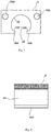
Fig. 2 is a schematic side view illustrating the transfer apparatus according to the first embodiment of the invention, seen along direction II-II inFig. 1 . -
Fig. 3 is a schematic cross-sectional view illustrating the transfer apparatus according to the first embodiment of the invention, seen along direction III-III inFig. 1 . -
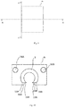
Fig. 4 is a schematic plan view illustrating an opposite member according to the first embodiment of the invention. -
Fig. 5 is a schematic side view illustrating the opposite member according to the first embodiment of the invention, seen along direction V-V inFig. 4 . -
Fig. 6 is a schematic plan view illustrating a transfer member according to the first embodiment of the invention. -
Fig. 7 is a schematic side view illustrating the transfer member according to the first embodiment of the invention, seen along direction VII-VII inFig. 6 . -
Fig. 8 is a schematic cross-sectional view illustrating the transfer member according to the first embodiment of the invention, seen along direction VIII-VIII inFig. 6 . -
Fig. 9 is a schematic plan view illustrating the transfer member into which the opposite member according to the first embodiment of the invention has been inserted. -
Fig. 10 is a schematic side view illustrating the transfer member into which the opposite member according to the first embodiment of the invention has been inserted, seen along direction X-X inFig. 9 . -
Fig. 11 is a schematic cross-sectional view illustrating the transfer member into which the opposite member according to the first embodiment of the invention has been inserted, seen along direction XI-XI inFig. 9 . -
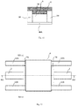
Fig. 12 is a schematic plan view illustrating a transfer apparatus according to a second embodiment of the invention. -
Fig. 13 is a schematic side view illustrating the transfer apparatus according to the second embodiment of the invention, seen along direction XIII-XIII inFig. 12 . -
Fig. 14 is a schematic cross-sectional view illustrating the transfer apparatus according to the second embodiment of the invention, seen along direction XIV-XIV inFig. 12 . -
Fig. 15 is a schematic plan view illustrating a fixing member according to the second embodiment of the invention. -
Fig. 16 is a schematic side view illustrating the fixing member according to the second embodiment of the invention, seen along direction XVI-XVI inFig. 15 . -
Fig. 17 is a schematic plan view illustrating a transfer member into which an opposite member and the fixing member according to the second embodiment of the invention have been inserted. -
Fig. 18 is a schematic side view illustrating the transfer member into which the opposite member and the fixing member according to the second embodiment of the invention have been inserted, seen along direction XVIII-XVIII inFig. 17 . -
Fig. 19 is a schematic cross-sectional view illustrating the transfer member into which the opposite member and the fixing member according to the second embodiment of the invention have been inserted, seen along direction XIX-XIX inFig. 17 . -
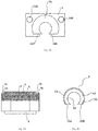
Fig. 20 is a schematic side view illustrating an opposite member according to a third embodiment. -
Fig. 21 is a schematic plan view illustrating an opposite member according to a fourth embodiment. -
Fig. 22 is a schematic side view illustrating the opposite member according to the fourth embodiment, seen along direction XXII-XXII inFig. 21 . -
Fig. 23 is a schematic side view illustrating a transfer member according to the fourth embodiment. -
Fig. 24 is a schematic side view illustrating opposite members according to other embodiments. -
Fig. 25 is a schematic side view illustrating a transfer apparatus according to another embodiment. -
Fig. 26 is a schematic plan view illustrating a rail and a wheel according to another embodiment. - Embodiments of the invention will be described below. In the description of the drawings given below, the same or similar parts are denoted by the same or similar reference numerals. However, the drawings are illustrated schematically. Accordingly, specific dimensions and the like should be decided with reference to the following description. It will be appreciated that the relationship or the ratio between dimensions may be different among the drawings.
- As illustrated in
Fig. 1 ,Fig. 2, and Fig. 3 , a transfer apparatus according to a first embodiment of the invention includes a rod-shaped member 2 that includes a magnetic material, an arc-shapedopposite member 3 that is opposed to a part of a side surface of the rod-shaped member 2, includes a magnetic material, and hasconnection surfaces shaped member 2, that make connection between an outer peripheral surface and an inner peripheral surface, a driving device configured to rotate the rod-shaped member 2 about the central axis of the rod-shaped member 2 to change a relative position between the rod-shaped member 2 and theopposite member 3, and atransfer member 6 that has theopposite member 3 therein and has holdingsurfaces connection surfaces opposite member 3. - The cylindrical rod-
shaped member 2 is held by, for example, a bearing. The rod-shaped member 2 is a male magnetic screw. A trapezoidal or rectangular projection made of a ferromagnetic material is provided spirally on an outer peripheral surface of the rod-shaped member 2. Alternatively, an S pole magnetized zone and an N pole magnetized zone that are permanent magnets may be alternately provided spirally on the outer peripheral surface of the rod-shapedmember 2. The rod-shapedmember 2 may be inserted into a thin-walled pipe made of a nonmagnetic material. The pipe is made of, for example, stainless steel. The rod-shapedmember 2 and the pipe are integrated with each other and, when the rod-shapedmember 2 rotates, the pipe also rotates about the central axis of the rod-shapedmember 2. - As illustrated in
Fig. 4 and Fig. 5 , the arc-shapedopposite member 3 is formed by removing a part of a cylindrical side wall from one end portion to the other end portion in the longitudinal direction. Accordingly, the arc-shapedopposite member 3 includes an outerperipheral surface 23, an innerperipheral surface 33, and the connection surfaces 13A and 13B that make connection between the outerperipheral surface 23 and the innerperipheral surface 33. The cross-section of the outerperipheral surface 23 and the cross-section of the innerperipheral surface 33 are arc-shaped. Theopposite member 3 is a magnetic nut including a hard magnetic material and the inner periphery of theopposite member 3 is larger than the outer periphery of the rod-shapedmember 2. As illustrated inFig. 2 and Fig. 3 , the rod-shapedmember 2 passes inside the nut-shapedopposite member 3. An S pole magnetized zone and an N pole magnetized zone that are permanent magnets are alternately provided spirally on the innerperipheral surface 33 of the hole of theopposite member 3. The pitch of the magnetized zones of theopposite member 3 is substantially the same as the pitch of the magnetized zones of the rod-shapedmember 2. - As illustrated in
Fig. 6 ,Fig. 7, and Fig. 8 , thetransfer member 6 has, for example, a rectangular parallelepiped shape having aconcave portion 26 on a bottom surface. However, thetransfer member 6 has any outside shape. An article to be transferred or the like is disposed on thetransfer member 6. Alternatively, thetransfer member 6 makes contact with and pushes the article to be transferred or the like. At least a part of aninner wall 36 of theconcave portion 26 of thetransfer member 6 has a shape that makes contact with the outerperipheral surface 23 of theopposite member 3 illustrated inFig. 5 . As illustrated inFig. 7 and Fig. 8 ,steps inner wall 36 of theconcave portion 26 of thetransfer member 6. Thesteps transfer member 6. An upper surface of thestep 46A makes contact with theconnection surface 13A of theopposite member 3 illustrated inFig. 5 and functions as the holdingsurface 16A that holds theopposite member 3. In addition, an upper surface of thestep 46B illustrated inFig. 7 makes contact with theconnection surface 13B of theopposite member 3 illustrated inFig. 5 and functions as the holdingsurface 16B that holds theopposite member 3. - In addition, as illustrated in
Fig. 7 , thetransfer member 6 has through-holes linear guides Fig. 1 are inserted. The through-holes member 2. Thetransfer member 6 is made of, for example, metal. Thelinear guides Fig. 1 ,Fig. 2, and Fig. 3 function as guides that allow thetransfer member 6 to move in the direction of the central axis of the rod-shapedmember 2 and prevent thetransfer member 6 from rotating. - When the transfer apparatus according to the first embodiment is assembled, the
opposite member 3 is inserted into theconcave portion 26 of thetransfer member 6 as illustrated inFig. 9, Fig. 10 , andFig. 11 . The outerperipheral surface 23 of theopposite member 3 illustrated inFig. 5 makes contact with and engages with theinner wall 36 of theconcave portion 26 of thetransfer member 6 illustrated inFig. 7 . In addition, the connection surfaces 13A and 13B of theopposite member 3 illustrated inFig. 5 make contact with and engage with the holdingsurfaces transfer member 6 illustrated inFig. 7 , respectively. This prevents theopposite member 3 from rotating about the center of arcs of the cross-sections of the outerperipheral surface 23 and the innerperipheral surface 33 inside thetransfer member 6. - Next, as illustrated in
Fig. 1 ,Fig. 2, and Fig. 3 , thelinear guides holes transfer member 6. In addition, thelinear guides transfer member 6 in the direction of the long axes of thelinear guides transfer member 6 in the direction orthogonal to the long axes of thelinear guides transfer member 6. In addition, the rod-shapedmember 2 is passed through the hollow portion of theopposite member 3 and the rod-shapedmember 2 is rotatably held by a bearing or the like. The center of the circle in the cross-section of the rod-shapedmember 2 coincides with the center of the arcs in the cross-sections of the outerperipheral surface 23 and the innerperipheral surface 33 of theopposite member 3. In addition, a driving device is connected to one end or the like of the rod-shapedmember 2. The disposition of the driving device is fixed and the rod-shapedmember 2 connected to the driving device cannot move in the direction of the central axis thereof. - When the rod-shaped
member 2 is rotated by the driving device after assembly, a magnetic force acts between the magnetized zone of the rod-shapedmember 2 and the magnetized zone of theopposite member 3. Since theopposite member 3 is held by thetransfer member 6 and the rotation of thetransfer member 6 is prevented by thelinear guides opposite member 3 cannot rotate. Therefore, when the rod-shapedmember 2 is rotated, theopposite member 3 moves along the central axis of the rod-shapedmember 2 and thetransfer member 6 also moves with the movement of theopposite member 3. - Since a sintered magnet or the like is easily broken by receiving a large force, it is preferable not to fix the
opposite member 3 to thetransfer member 6 by press-fitting or screws. In addition, when the transfer apparatus is used in a clean room or the like or when the transfer apparatus is used to transfer articles captured in human bodies, such as foods or medicines, it is preferable not to secure theopposite member 3 to thetransfer member 6 with an adhesive. This is because a part of an adhesive may change to powder and scatter due to aged deterioration or temperature changes, be attached to the article transferred by the transfer apparatus as a foreign matter, and adversely affect the article. - In contrast, in the transfer apparatus according to the first embodiment, the connection surfaces 13A and 13B of the
opposite member 3 make contact with the holdingsurfaces transfer member 6. Therefore, when the rod-shapedmember 2 rotates, a rotating force is applied to theopposite member 3 and thus thetransfer member 6. However, since thetransfer member 6 is prevented from rotating by thelinear guides opposite member 3 is blocked by a coupling surface between the connection surfaces 13A and 13B and the holdingsurfaces opposite member 3 can be prevented from rotating without securing theopposite member 3 to thetransfer member 6 by press-fitting, screws, or an adhesive. - A transfer apparatus according to a second embodiment further includes fixing
members transfer member 6 so as to make contact with the end surfaces of theopposite member 3 as illustrated inFig. 12 ,Fig. 13, and Fig. 14 . The other components of the transfer apparatus according to the second embodiment are the same as those of the first embodiment. - As illustrated in
Fig. 15 and Fig. 16 , the fixingmember 7A has aninsertion portion 17A that is inserted into theconcave portion 26 of thetransfer member 6 and has an end surface making contact with theopposite member 3 and aflange portion 27A, making contact with a side surface of thetransfer member 6, that is connected to theinsertion portion 17A. For example, the cross-section of theinsertion portion 17A of the fixingmember 7A has the same shape as the cross-section of theopposite member 3 and theinsertion portion 17A includes an outer peripheral surface, an inner peripheral surface, and a connection surface that makes contact between the outer peripheral surface and the inner peripheral surface. The cross-section of the outer peripheral surface and the cross-section of the inner peripheral surface are arc-shaped. The fixingmember 7B has the same shape as the fixingmember 7A. The fixingmembers - When the transfer apparatus according to the second embodiment is assembled, the
opposite member 3 is inserted into theconcave portion 26 of thetransfer member 6 as in the first embodiment. Next, as illustrated inFig. 17 ,Fig. 18, and Fig. 19 , the fixingmembers concave portion 26 of thetransfer member 6 so as to sandwich theopposite member 3. The outer peripheral surfaces of the fixingmembers inner wall 36 of theconcave portion 26 of thetransfer member 6. In addition, the connection surfaces of the fixingmembers surfaces transfer member 6. In addition, the end surface of theinsertion portion 17A of the fixingmember 7A makes contact with one end surface of theopposite member 3 and an end surface of an insertion portion 17B of the fixingmember 7B makes contact with the other end surface of theopposite member 3. - The fixing
members concave portion 26 of thetransfer member 6 so as not to move in the direction of the central axis of the rod-shapedmember 2. Therefore, the outer dimensions of the insertion portions of the fixingmembers opposite member 3. Alternatively, the flange portions of the fixingmembers transfer member 6 by screws. - When the rod-shaped
member 2 illustrated inFig. 12 ,Fig. 13, and Fig. 14 is rotated, theopposite member 3 moves in the direction of the central axis of the rod-shapedmember 2 and thetransfer member 6 moves together with theopposite member 3 by a friction force. The fixingmembers transfer member 6 with respect to the movement of theopposite member 3. It should be noted here that only one of the fixingmembers transfer member 6. Alternatively, one of the fixingmembers transfer member 6. In this case, theopposite member 3 is inserted into thetransfer member 6 from the side with which the fixing member is not integrated. - In a transfer apparatus according to a third embodiment, as illustrated in
Fig. 20 , theopposite member 3 has amagnetic material member 43 having the innerperipheral surface 33 and acover 53 having the outerperipheral surface 23 and covering themagnetic material member 43. As described in the first embodiment, the S pole magnetized zone and the N pole magnetized zone that are permanent magnets are alternately provided spirally on the innerperipheral surface 33. Thecover 53 is made of, for example, a ferromagnetic material. Thecover 53 improves the magnetic force between theopposite member 3 and the rod-shapedmember 2 by causing a magnetic flux from the innerperipheral surface 33 to the outerperipheral surface 23 to flow back to the innerperipheral surface 33. The other components of the transfer apparatus according to the third embodiment are the same as those of the first or second embodiment. - In a transfer apparatus according to a fourth embodiment, a
concave portion 63 is provided in the outerperipheral surface 23 of theopposite member 3 as illustrated inFig. 21 and Fig. 22 and aprojection 66 that engages with theconcave portion 63 provided in the outerperipheral surface 23 of theopposite member 3 is provided on thetransfer member 6 as illustrated inFig. 23 . As illustrated inFig. 22 , theconcave portion 63 provided in the outerperipheral surface 23 of theopposite member 3 does not need to reach the innerperipheral surface 33. Theopposite member 3 can be fixed to thetransfer member 6 more certainly by engaging theconcave portion 63 with theprojection 66. The other components of the transfer apparatus according to the fourth embodiment are the same as those of the first, second, or third embodiment. - Although the invention has been described by embodiments as described above, it should not be understood that the description and the drawings that are parts of the disclosure limit the invention. It must be apparent to those skilled in the art that various alternative embodiments, examples, and operational techniques are clarified based on the disclosure. For example, an example in which the linear guides passing through the transfer member are used has been described in the embodiments. However, the member that holds the transfer member so that the transfer member can move in the direction of the central axis of the rod-shaped member and cannot rotate is not limited to the linear guides that pass through the transfer member. For example, as illustrated in
Fig. 25 andFig. 26 , thetransfer member 6 may be held so that thetransfer member 6 can move in the direction of the central axis of the rod-shapedmember 2 and cannot rotate by providing a guide such as arail 22 that has a hexagonal cross-section and has a V-shaped projection on the side thereof on a board and providing guide followers such aswheels rail 22 on the bottom surface of the transfer member. Therail 22 extends in parallel with the direction of the central axis of the rod-shapedmember 2. In addition, theopposite member 3 may have various shapes as illustrated inFig. 24 . As described above, it should be understood that the invention encompasses various embodiments and the like not described in the description. -
- 2: rod-shaped member
- 3: opposite member
- 5: cover
- 6: transfer member
- 7A, 7B: fixing member
- 12A, 12B: linear guide
- 13A, 13B: connection surface
- 16A, 16B: holding surface
- 17A, 17B: insertion portion
- 22: rail
- 23: outer peripheral surface
- 26: concave portion
- 27A: flange portion
- 32A, 32B: wheel
- 33: inner peripheral surface
- 36: inner wall
- 43: magnetic material member
- 46A, 46B: step
- 53: cover
- 56A, 56B: through-hole
- 63: concave portion
- 66: projection
Claims (10)
- A transfer apparatus comprising:a rod-shaped member that includes a magnetic material;an arc-shaped opposite member that is opposed to a part of a side surface of the rod-shaped member, includes a magnetic material, and has a connection surface that makes connection between an outer peripheral surface and an inner peripheral surface;a driving device configured to rotate the rod-shaped member about a central axis of the rod-shaped member to change a relative position between the rod-shaped member and the opposite member; anda transfer member that has the opposite member therein and has a holding surface that makes contact with the connection surface of the arc-shaped opposite member.
- The transfer apparatus according to claim 1,
wherein the connection surface of the opposite member is parallel with the central axis of the rod-shaped member. - The transfer apparatus according to claim 1 or 2,
wherein the transfer member has an inner wall that makes contact with the outer peripheral surface of the opposite member. - The transfer apparatus according to any one of claims 1 to 3, further comprising a fixing member that is fixed to the transfer member so as to make contact with an end surface of the opposite member.
- The transfer apparatus according to any one of claims 1 to 4,
wherein the opposite member includes a magnetic material member that has the inner peripheral surface and a cover that has the outer peripheral surface and covers the magnetic material member. - The transfer apparatus according to claim 5,
wherein the cover is made of a ferromagnetic material. - The transfer apparatus according to any one of claims 1 to 5,
wherein a concave portion is provided in the outer peripheral surface of the opposite member and
a projection that engages with the concave portion provided in the outer peripheral surface of the opposite member is provided on the transfer member. - The transfer apparatus according to claim 1, further comprising a guide configured to allow the transfer member to move in a direction of the central axis of the rod-shaped member and prevent the transfer member from rotating.
- The transfer apparatus according to claim 8,
wherein the transfer member has a through-hole and the guide passes through the through-hole of the transfer member. - The transfer apparatus according to claim 8,
wherein the guide is a rail and the transfer member has a wheel that engages with the rail.
Applications Claiming Priority (1)
| Application Number | Priority Date | Filing Date | Title |
|---|---|---|---|
| PCT/JP2016/070444 WO2018011859A1 (en) | 2016-07-11 | 2016-07-11 | Conveyance device |
Publications (3)
| Publication Number | Publication Date |
|---|---|
| EP3483476A1 true EP3483476A1 (en) | 2019-05-15 |
| EP3483476A4 EP3483476A4 (en) | 2020-03-18 |
| EP3483476B1 EP3483476B1 (en) | 2023-06-21 |
Family
ID=60952010
Family Applications (1)
| Application Number | Title | Priority Date | Filing Date |
|---|---|---|---|
| EP16908763.2A Active EP3483476B1 (en) | 2016-07-11 | 2016-07-11 | Conveyance device |
Country Status (4)
| Country | Link |
|---|---|
| US (1) | US10611581B2 (en) |
| EP (1) | EP3483476B1 (en) |
| CN (1) | CN109477562A (en) |
| WO (1) | WO2018011859A1 (en) |
Family Cites Families (15)
| Publication number | Priority date | Publication date | Assignee | Title |
|---|---|---|---|---|
| JP2777131B2 (en) * | 1987-11-09 | 1998-07-16 | 旭精工株式会社 | A mechanism that converts rotary motion into linear motion |
| US5047676A (en) | 1990-04-02 | 1991-09-10 | Hitachi Metals, Ltd. | Brushless linear actuator with sensor-activated coils |
| DE69432192T2 (en) * | 1993-10-12 | 2003-12-04 | Smc K.K., Tokio/Tokyo | linear actuator |
| JP2685723B2 (en) * | 1994-04-26 | 1997-12-03 | シーケーディ株式会社 | Magnetic screw |
| KR100224117B1 (en) * | 1995-08-29 | 1999-10-15 | 아마노 시게루 | Magnetic screw carrier device |
| DE69622336T2 (en) * | 1995-09-13 | 2003-02-27 | Shimonishi Seisakusyo Co., Ltd. | transport device |
| JP3122367B2 (en) * | 1996-05-28 | 2001-01-09 | シーケーディ株式会社 | Magnetic screw conveyor |
| JP3124940B2 (en) * | 1996-11-27 | 2001-01-15 | 光洋機械工業株式会社 | Magnetic screw device |
| JP4264868B2 (en) * | 2001-07-18 | 2009-05-20 | 日立金属株式会社 | Conveying mechanism using magnetic screw |
| JP2010117598A (en) * | 2008-11-13 | 2010-05-27 | Sharp Corp | Fixing apparatus, image forming apparatus, heating member, and method of fixing heating element of heating member |
| JP5687049B2 (en) * | 2010-12-27 | 2015-03-18 | キヤノンアネルバ株式会社 | Conveying apparatus and vacuum processing apparatus |
| DE102013203066A1 (en) * | 2013-02-25 | 2014-08-28 | Robert Bosch Gmbh | Transport device and method for operating the transport device |
| CN103303686B (en) * | 2013-07-01 | 2016-02-03 | 沈阳工业大学 | The dustless conveyer of energy-saving permanent magnet suspension |
| CN103979251A (en) * | 2014-06-05 | 2014-08-13 | 安徽理工大学 | Magnetic levitation synchronous belt conveyor |
| CN204999309U (en) * | 2015-08-28 | 2016-01-27 | 杭州东华链条集团有限公司 | Spiral magnetism conveyer |
-
2016
- 2016-07-11 EP EP16908763.2A patent/EP3483476B1/en active Active
- 2016-07-11 WO PCT/JP2016/070444 patent/WO2018011859A1/en not_active Ceased
- 2016-07-11 CN CN201680087508.7A patent/CN109477562A/en active Pending
- 2016-07-11 US US16/316,480 patent/US10611581B2/en active Active
Also Published As
| Publication number | Publication date |
|---|---|
| WO2018011859A1 (en) | 2018-01-18 |
| US10611581B2 (en) | 2020-04-07 |
| US20190218043A1 (en) | 2019-07-18 |
| CN109477562A (en) | 2019-03-15 |
| EP3483476A4 (en) | 2020-03-18 |
| EP3483476B1 (en) | 2023-06-21 |
Similar Documents
| Publication | Publication Date | Title |
|---|---|---|
| EP2891029B1 (en) | Friction hinge system | |
| CN101307817B (en) | Gearing for an adjustment device, especially an automotive adjustment device | |
| US11035402B2 (en) | Method of assembling a rolling element intermediate shaft assembly | |
| JP2010093869A (en) | Motor | |
| US10578241B2 (en) | Closure device for securing an electronic device on a holding device | |
| US9103423B2 (en) | Linear actuator | |
| US6347462B1 (en) | Measuring cable travel sensor with housing | |
| CN102442342B (en) | Rack driven electric power steering apparatus | |
| CN101956757B (en) | Hinging device | |
| CN107923501B (en) | Ball screw | |
| EP2251564A1 (en) | Ball speed reducer and rotary table device using same | |
| CN103032471A (en) | Split type bearing cage connection scheme | |
| JP2010253649A5 (en) | ||
| EP2778493A3 (en) | Filling connection, use thereof and filling method | |
| CN104334898B (en) | Outer barrel is divided tripartite linear motion bearing | |
| US20170373557A1 (en) | Linear bearing for an electromagnetic solenoid and solenoid having said linear bearing | |
| US10611581B2 (en) | Transfer apparatus | |
| TW201837344A (en) | Screw device | |
| JP2015059633A (en) | Ball screw | |
| CN107923763A (en) | Position sensor | |
| DE102016015731B4 (en) | magnetic clutch rotor | |
| KR20210023335A (en) | Magnetic coupling for conveyor | |
| CN103883695B (en) | Drive mechanism | |
| CN109067047A (en) | Winding framework, magnetic suspension bearing and motor | |
| JP2006138405A (en) | Nut with flange and sliding screw device |
Legal Events
| Date | Code | Title | Description |
|---|---|---|---|
| STAA | Information on the status of an ep patent application or granted ep patent |
Free format text: STATUS: THE INTERNATIONAL PUBLICATION HAS BEEN MADE |
|
| PUAI | Public reference made under article 153(3) epc to a published international application that has entered the european phase |
Free format text: ORIGINAL CODE: 0009012 |
|
| STAA | Information on the status of an ep patent application or granted ep patent |
Free format text: STATUS: REQUEST FOR EXAMINATION WAS MADE |
|
| 17P | Request for examination filed |
Effective date: 20181212 |
|
| AK | Designated contracting states |
Kind code of ref document: A1 Designated state(s): AL AT BE BG CH CY CZ DE DK EE ES FI FR GB GR HR HU IE IS IT LI LT LU LV MC MK MT NL NO PL PT RO RS SE SI SK SM TR |
|
| AX | Request for extension of the european patent |
Extension state: BA ME |
|
| DAV | Request for validation of the european patent (deleted) | ||
| DAX | Request for extension of the european patent (deleted) | ||
| A4 | Supplementary search report drawn up and despatched |
Effective date: 20200213 |
|
| RIC1 | Information provided on ipc code assigned before grant |
Ipc: F16H 25/24 20060101AFI20200207BHEP Ipc: H01F 7/02 20060101ALI20200207BHEP Ipc: B65G 54/02 20060101ALI20200207BHEP |
|
| STAA | Information on the status of an ep patent application or granted ep patent |
Free format text: STATUS: EXAMINATION IS IN PROGRESS |
|
| 17Q | First examination report despatched |
Effective date: 20211203 |
|
| GRAP | Despatch of communication of intention to grant a patent |
Free format text: ORIGINAL CODE: EPIDOSNIGR1 |
|
| STAA | Information on the status of an ep patent application or granted ep patent |
Free format text: STATUS: GRANT OF PATENT IS INTENDED |
|
| INTG | Intention to grant announced |
Effective date: 20230313 |
|
| GRAS | Grant fee paid |
Free format text: ORIGINAL CODE: EPIDOSNIGR3 |
|
| GRAA | (expected) grant |
Free format text: ORIGINAL CODE: 0009210 |
|
| STAA | Information on the status of an ep patent application or granted ep patent |
Free format text: STATUS: THE PATENT HAS BEEN GRANTED |
|
| AK | Designated contracting states |
Kind code of ref document: B1 Designated state(s): AL AT BE BG CH CY CZ DE DK EE ES FI FR GB GR HR HU IE IS IT LI LT LU LV MC MK MT NL NO PL PT RO RS SE SI SK SM TR |
|
| REG | Reference to a national code |
Ref country code: CH Ref legal event code: EP |
|
| REG | Reference to a national code |
Ref country code: DE Ref legal event code: R096 Ref document number: 602016080542 Country of ref document: DE |
|
| REG | Reference to a national code |
Ref country code: AT Ref legal event code: REF Ref document number: 1581095 Country of ref document: AT Kind code of ref document: T Effective date: 20230715 |
|
| REG | Reference to a national code |
Ref country code: IE Ref legal event code: FG4D |
|
| REG | Reference to a national code |
Ref country code: LT Ref legal event code: MG9D |
|
| REG | Reference to a national code |
Ref country code: NL Ref legal event code: MP Effective date: 20230621 |
|
| PG25 | Lapsed in a contracting state [announced via postgrant information from national office to epo] |
Ref country code: SE Free format text: LAPSE BECAUSE OF FAILURE TO SUBMIT A TRANSLATION OF THE DESCRIPTION OR TO PAY THE FEE WITHIN THE PRESCRIBED TIME-LIMIT Effective date: 20230621 Ref country code: NO Free format text: LAPSE BECAUSE OF FAILURE TO SUBMIT A TRANSLATION OF THE DESCRIPTION OR TO PAY THE FEE WITHIN THE PRESCRIBED TIME-LIMIT Effective date: 20230921 |
|
| REG | Reference to a national code |
Ref country code: AT Ref legal event code: MK05 Ref document number: 1581095 Country of ref document: AT Kind code of ref document: T Effective date: 20230621 |
|
| PG25 | Lapsed in a contracting state [announced via postgrant information from national office to epo] |
Ref country code: RS Free format text: LAPSE BECAUSE OF FAILURE TO SUBMIT A TRANSLATION OF THE DESCRIPTION OR TO PAY THE FEE WITHIN THE PRESCRIBED TIME-LIMIT Effective date: 20230621 Ref country code: NL Free format text: LAPSE BECAUSE OF FAILURE TO SUBMIT A TRANSLATION OF THE DESCRIPTION OR TO PAY THE FEE WITHIN THE PRESCRIBED TIME-LIMIT Effective date: 20230621 Ref country code: LV Free format text: LAPSE BECAUSE OF FAILURE TO SUBMIT A TRANSLATION OF THE DESCRIPTION OR TO PAY THE FEE WITHIN THE PRESCRIBED TIME-LIMIT Effective date: 20230621 Ref country code: LT Free format text: LAPSE BECAUSE OF FAILURE TO SUBMIT A TRANSLATION OF THE DESCRIPTION OR TO PAY THE FEE WITHIN THE PRESCRIBED TIME-LIMIT Effective date: 20230621 Ref country code: HR Free format text: LAPSE BECAUSE OF FAILURE TO SUBMIT A TRANSLATION OF THE DESCRIPTION OR TO PAY THE FEE WITHIN THE PRESCRIBED TIME-LIMIT Effective date: 20230621 Ref country code: GR Free format text: LAPSE BECAUSE OF FAILURE TO SUBMIT A TRANSLATION OF THE DESCRIPTION OR TO PAY THE FEE WITHIN THE PRESCRIBED TIME-LIMIT Effective date: 20230922 |
|
| PG25 | Lapsed in a contracting state [announced via postgrant information from national office to epo] |
Ref country code: FI Free format text: LAPSE BECAUSE OF FAILURE TO SUBMIT A TRANSLATION OF THE DESCRIPTION OR TO PAY THE FEE WITHIN THE PRESCRIBED TIME-LIMIT Effective date: 20230621 |
|
| PG25 | Lapsed in a contracting state [announced via postgrant information from national office to epo] |
Ref country code: SK Free format text: LAPSE BECAUSE OF FAILURE TO SUBMIT A TRANSLATION OF THE DESCRIPTION OR TO PAY THE FEE WITHIN THE PRESCRIBED TIME-LIMIT Effective date: 20230621 |
|
| PG25 | Lapsed in a contracting state [announced via postgrant information from national office to epo] |
Ref country code: ES Free format text: LAPSE BECAUSE OF FAILURE TO SUBMIT A TRANSLATION OF THE DESCRIPTION OR TO PAY THE FEE WITHIN THE PRESCRIBED TIME-LIMIT Effective date: 20230621 |
|
| PG25 | Lapsed in a contracting state [announced via postgrant information from national office to epo] |
Ref country code: IS Free format text: LAPSE BECAUSE OF FAILURE TO SUBMIT A TRANSLATION OF THE DESCRIPTION OR TO PAY THE FEE WITHIN THE PRESCRIBED TIME-LIMIT Effective date: 20231021 |
|
| PG25 | Lapsed in a contracting state [announced via postgrant information from national office to epo] |
Ref country code: SM Free format text: LAPSE BECAUSE OF FAILURE TO SUBMIT A TRANSLATION OF THE DESCRIPTION OR TO PAY THE FEE WITHIN THE PRESCRIBED TIME-LIMIT Effective date: 20230621 Ref country code: SK Free format text: LAPSE BECAUSE OF FAILURE TO SUBMIT A TRANSLATION OF THE DESCRIPTION OR TO PAY THE FEE WITHIN THE PRESCRIBED TIME-LIMIT Effective date: 20230621 Ref country code: RO Free format text: LAPSE BECAUSE OF FAILURE TO SUBMIT A TRANSLATION OF THE DESCRIPTION OR TO PAY THE FEE WITHIN THE PRESCRIBED TIME-LIMIT Effective date: 20230621 Ref country code: PT Free format text: LAPSE BECAUSE OF FAILURE TO SUBMIT A TRANSLATION OF THE DESCRIPTION OR TO PAY THE FEE WITHIN THE PRESCRIBED TIME-LIMIT Effective date: 20231023 Ref country code: IS Free format text: LAPSE BECAUSE OF FAILURE TO SUBMIT A TRANSLATION OF THE DESCRIPTION OR TO PAY THE FEE WITHIN THE PRESCRIBED TIME-LIMIT Effective date: 20231021 Ref country code: ES Free format text: LAPSE BECAUSE OF FAILURE TO SUBMIT A TRANSLATION OF THE DESCRIPTION OR TO PAY THE FEE WITHIN THE PRESCRIBED TIME-LIMIT Effective date: 20230621 Ref country code: EE Free format text: LAPSE BECAUSE OF FAILURE TO SUBMIT A TRANSLATION OF THE DESCRIPTION OR TO PAY THE FEE WITHIN THE PRESCRIBED TIME-LIMIT Effective date: 20230621 Ref country code: CZ Free format text: LAPSE BECAUSE OF FAILURE TO SUBMIT A TRANSLATION OF THE DESCRIPTION OR TO PAY THE FEE WITHIN THE PRESCRIBED TIME-LIMIT Effective date: 20230621 Ref country code: AT Free format text: LAPSE BECAUSE OF FAILURE TO SUBMIT A TRANSLATION OF THE DESCRIPTION OR TO PAY THE FEE WITHIN THE PRESCRIBED TIME-LIMIT Effective date: 20230621 |
|
| PG25 | Lapsed in a contracting state [announced via postgrant information from national office to epo] |
Ref country code: PL Free format text: LAPSE BECAUSE OF FAILURE TO SUBMIT A TRANSLATION OF THE DESCRIPTION OR TO PAY THE FEE WITHIN THE PRESCRIBED TIME-LIMIT Effective date: 20230621 |
|
| REG | Reference to a national code |
Ref country code: CH Ref legal event code: PL |
|
| PG25 | Lapsed in a contracting state [announced via postgrant information from national office to epo] |
Ref country code: MC Free format text: LAPSE BECAUSE OF FAILURE TO SUBMIT A TRANSLATION OF THE DESCRIPTION OR TO PAY THE FEE WITHIN THE PRESCRIBED TIME-LIMIT Effective date: 20230621 |
|
| REG | Reference to a national code |
Ref country code: BE Ref legal event code: MM Effective date: 20230731 |
|
| PG25 | Lapsed in a contracting state [announced via postgrant information from national office to epo] |
Ref country code: LU Free format text: LAPSE BECAUSE OF NON-PAYMENT OF DUE FEES Effective date: 20230711 |
|
| REG | Reference to a national code |
Ref country code: DE Ref legal event code: R097 Ref document number: 602016080542 Country of ref document: DE |
|
| PG25 | Lapsed in a contracting state [announced via postgrant information from national office to epo] |
Ref country code: MC Free format text: LAPSE BECAUSE OF FAILURE TO SUBMIT A TRANSLATION OF THE DESCRIPTION OR TO PAY THE FEE WITHIN THE PRESCRIBED TIME-LIMIT Effective date: 20230621 Ref country code: LU Free format text: LAPSE BECAUSE OF NON-PAYMENT OF DUE FEES Effective date: 20230711 |
|
| REG | Reference to a national code |
Ref country code: IE Ref legal event code: MM4A |
|
| PLBE | No opposition filed within time limit |
Free format text: ORIGINAL CODE: 0009261 |
|
| STAA | Information on the status of an ep patent application or granted ep patent |
Free format text: STATUS: NO OPPOSITION FILED WITHIN TIME LIMIT |
|
| PG25 | Lapsed in a contracting state [announced via postgrant information from national office to epo] |
Ref country code: DK Free format text: LAPSE BECAUSE OF FAILURE TO SUBMIT A TRANSLATION OF THE DESCRIPTION OR TO PAY THE FEE WITHIN THE PRESCRIBED TIME-LIMIT Effective date: 20230621 Ref country code: CH Free format text: LAPSE BECAUSE OF NON-PAYMENT OF DUE FEES Effective date: 20230731 |
|
| PG25 | Lapsed in a contracting state [announced via postgrant information from national office to epo] |
Ref country code: SI Free format text: LAPSE BECAUSE OF FAILURE TO SUBMIT A TRANSLATION OF THE DESCRIPTION OR TO PAY THE FEE WITHIN THE PRESCRIBED TIME-LIMIT Effective date: 20230621 |
|
| 26N | No opposition filed |
Effective date: 20240322 |
|
| GBPC | Gb: european patent ceased through non-payment of renewal fee |
Effective date: 20230921 |
|
| PG25 | Lapsed in a contracting state [announced via postgrant information from national office to epo] |
Ref country code: SI Free format text: LAPSE BECAUSE OF FAILURE TO SUBMIT A TRANSLATION OF THE DESCRIPTION OR TO PAY THE FEE WITHIN THE PRESCRIBED TIME-LIMIT Effective date: 20230621 Ref country code: BE Free format text: LAPSE BECAUSE OF NON-PAYMENT OF DUE FEES Effective date: 20230731 |
|
| PG25 | Lapsed in a contracting state [announced via postgrant information from national office to epo] |
Ref country code: IE Free format text: LAPSE BECAUSE OF NON-PAYMENT OF DUE FEES Effective date: 20230711 |
|
| PG25 | Lapsed in a contracting state [announced via postgrant information from national office to epo] |
Ref country code: GB Free format text: LAPSE BECAUSE OF NON-PAYMENT OF DUE FEES Effective date: 20230921 |
|
| PG25 | Lapsed in a contracting state [announced via postgrant information from national office to epo] |
Ref country code: IE Free format text: LAPSE BECAUSE OF NON-PAYMENT OF DUE FEES Effective date: 20230711 Ref country code: GB Free format text: LAPSE BECAUSE OF NON-PAYMENT OF DUE FEES Effective date: 20230921 Ref country code: FR Free format text: LAPSE BECAUSE OF NON-PAYMENT OF DUE FEES Effective date: 20230821 |
|
| REG | Reference to a national code |
Ref country code: DE Ref legal event code: R081 Ref document number: 602016080542 Country of ref document: DE Owner name: AZBIL TELSTAR TECHNOLOGIES. S.L., ES Free format text: FORMER OWNER: AZBIL CORPORATION, TOKYO, JP Ref country code: DE Ref legal event code: R081 Ref document number: 602016080542 Country of ref document: DE Owner name: SYNTEGON TELSTAR TECHNOLOGIES, S.L.U., ES Free format text: FORMER OWNER: AZBIL CORPORATION, TOKYO, JP |
|
| PG25 | Lapsed in a contracting state [announced via postgrant information from national office to epo] |
Ref country code: BG Free format text: LAPSE BECAUSE OF FAILURE TO SUBMIT A TRANSLATION OF THE DESCRIPTION OR TO PAY THE FEE WITHIN THE PRESCRIBED TIME-LIMIT Effective date: 20230621 |
|
| PG25 | Lapsed in a contracting state [announced via postgrant information from national office to epo] |
Ref country code: BG Free format text: LAPSE BECAUSE OF FAILURE TO SUBMIT A TRANSLATION OF THE DESCRIPTION OR TO PAY THE FEE WITHIN THE PRESCRIBED TIME-LIMIT Effective date: 20230621 |
|
| PGFP | Annual fee paid to national office [announced via postgrant information from national office to epo] |
Ref country code: IT Payment date: 20241227 Year of fee payment: 10 |
|
| PG25 | Lapsed in a contracting state [announced via postgrant information from national office to epo] |
Ref country code: CY Free format text: LAPSE BECAUSE OF FAILURE TO SUBMIT A TRANSLATION OF THE DESCRIPTION OR TO PAY THE FEE WITHIN THE PRESCRIBED TIME-LIMIT; INVALID AB INITIO Effective date: 20160711 |
|
| REG | Reference to a national code |
Ref country code: DE Ref legal event code: R081 Ref document number: 602016080542 Country of ref document: DE Owner name: SYNTEGON TELSTAR TECHNOLOGIES, S.L.U., ES Free format text: FORMER OWNER: AZBIL TELSTAR TECHNOLOGIES. S.L., TERRASSA, ES |
|
| PG25 | Lapsed in a contracting state [announced via postgrant information from national office to epo] |
Ref country code: HU Free format text: LAPSE BECAUSE OF FAILURE TO SUBMIT A TRANSLATION OF THE DESCRIPTION OR TO PAY THE FEE WITHIN THE PRESCRIBED TIME-LIMIT; INVALID AB INITIO Effective date: 20160711 |
|
| PGFP | Annual fee paid to national office [announced via postgrant information from national office to epo] |
Ref country code: DE Payment date: 20250722 Year of fee payment: 10 |
|
| PG25 | Lapsed in a contracting state [announced via postgrant information from national office to epo] |
Ref country code: TR Free format text: LAPSE BECAUSE OF FAILURE TO SUBMIT A TRANSLATION OF THE DESCRIPTION OR TO PAY THE FEE WITHIN THE PRESCRIBED TIME-LIMIT Effective date: 20230621 |