EP3483462A1 - Rolling body uniform arrangement method for rolling bearing, rolling bearing, machine, and vehicle production method - Google Patents
Rolling body uniform arrangement method for rolling bearing, rolling bearing, machine, and vehicle production method Download PDFInfo
- Publication number
- EP3483462A1 EP3483462A1 EP18736129.0A EP18736129A EP3483462A1 EP 3483462 A1 EP3483462 A1 EP 3483462A1 EP 18736129 A EP18736129 A EP 18736129A EP 3483462 A1 EP3483462 A1 EP 3483462A1
- Authority
- EP
- European Patent Office
- Prior art keywords
- rolling
- rolling elements
- circumferential
- mounting space
- element mounting
- Prior art date
- Legal status (The legal status is an assumption and is not a legal conclusion. Google has not performed a legal analysis and makes no representation as to the accuracy of the status listed.)
- Granted
Links
Images




Classifications
-
- F—MECHANICAL ENGINEERING; LIGHTING; HEATING; WEAPONS; BLASTING
- F16—ENGINEERING ELEMENTS AND UNITS; GENERAL MEASURES FOR PRODUCING AND MAINTAINING EFFECTIVE FUNCTIONING OF MACHINES OR INSTALLATIONS; THERMAL INSULATION IN GENERAL
- F16C—SHAFTS; FLEXIBLE SHAFTS; ELEMENTS OR CRANKSHAFT MECHANISMS; ROTARY BODIES OTHER THAN GEARING ELEMENTS; BEARINGS
- F16C43/00—Assembling bearings
- F16C43/04—Assembling rolling-contact bearings
- F16C43/06—Placing rolling bodies in cages or bearings
- F16C43/065—Placing rolling bodies in cages or bearings in cages
-
- B—PERFORMING OPERATIONS; TRANSPORTING
- B23—MACHINE TOOLS; METAL-WORKING NOT OTHERWISE PROVIDED FOR
- B23P—METAL-WORKING NOT OTHERWISE PROVIDED FOR; COMBINED OPERATIONS; UNIVERSAL MACHINE TOOLS
- B23P15/00—Making specific metal objects by operations not covered by a single other subclass or a group in this subclass
- B23P15/003—Making specific metal objects by operations not covered by a single other subclass or a group in this subclass bearings
-
- B—PERFORMING OPERATIONS; TRANSPORTING
- B23—MACHINE TOOLS; METAL-WORKING NOT OTHERWISE PROVIDED FOR
- B23P—METAL-WORKING NOT OTHERWISE PROVIDED FOR; COMBINED OPERATIONS; UNIVERSAL MACHINE TOOLS
- B23P19/00—Machines for simply fitting together or separating metal parts or objects, or metal and non-metal parts, whether or not involving some deformation; Tools or devices therefor so far as not provided for in other classes
- B23P19/008—Machines for simply fitting together or separating metal parts or objects, or metal and non-metal parts, whether or not involving some deformation; Tools or devices therefor so far as not provided for in other classes the parts being continuously transported through the machine during assembling or disassembling
-
- B—PERFORMING OPERATIONS; TRANSPORTING
- B23—MACHINE TOOLS; METAL-WORKING NOT OTHERWISE PROVIDED FOR
- B23P—METAL-WORKING NOT OTHERWISE PROVIDED FOR; COMBINED OPERATIONS; UNIVERSAL MACHINE TOOLS
- B23P19/00—Machines for simply fitting together or separating metal parts or objects, or metal and non-metal parts, whether or not involving some deformation; Tools or devices therefor so far as not provided for in other classes
- B23P19/04—Machines for simply fitting together or separating metal parts or objects, or metal and non-metal parts, whether or not involving some deformation; Tools or devices therefor so far as not provided for in other classes for assembling or disassembling parts
-
- F—MECHANICAL ENGINEERING; LIGHTING; HEATING; WEAPONS; BLASTING
- F16—ENGINEERING ELEMENTS AND UNITS; GENERAL MEASURES FOR PRODUCING AND MAINTAINING EFFECTIVE FUNCTIONING OF MACHINES OR INSTALLATIONS; THERMAL INSULATION IN GENERAL
- F16C—SHAFTS; FLEXIBLE SHAFTS; ELEMENTS OR CRANKSHAFT MECHANISMS; ROTARY BODIES OTHER THAN GEARING ELEMENTS; BEARINGS
- F16C33/00—Parts of bearings; Special methods for making bearings or parts thereof
-
- F—MECHANICAL ENGINEERING; LIGHTING; HEATING; WEAPONS; BLASTING
- F16—ENGINEERING ELEMENTS AND UNITS; GENERAL MEASURES FOR PRODUCING AND MAINTAINING EFFECTIVE FUNCTIONING OF MACHINES OR INSTALLATIONS; THERMAL INSULATION IN GENERAL
- F16C—SHAFTS; FLEXIBLE SHAFTS; ELEMENTS OR CRANKSHAFT MECHANISMS; ROTARY BODIES OTHER THAN GEARING ELEMENTS; BEARINGS
- F16C43/00—Assembling bearings
- F16C43/04—Assembling rolling-contact bearings
- F16C43/06—Placing rolling bodies in cages or bearings
-
- F—MECHANICAL ENGINEERING; LIGHTING; HEATING; WEAPONS; BLASTING
- F16—ENGINEERING ELEMENTS AND UNITS; GENERAL MEASURES FOR PRODUCING AND MAINTAINING EFFECTIVE FUNCTIONING OF MACHINES OR INSTALLATIONS; THERMAL INSULATION IN GENERAL
- F16C—SHAFTS; FLEXIBLE SHAFTS; ELEMENTS OR CRANKSHAFT MECHANISMS; ROTARY BODIES OTHER THAN GEARING ELEMENTS; BEARINGS
- F16C19/00—Bearings with rolling contact, for exclusively rotary movement
- F16C19/02—Bearings with rolling contact, for exclusively rotary movement with bearing balls essentially of the same size in one or more circular rows
- F16C19/04—Bearings with rolling contact, for exclusively rotary movement with bearing balls essentially of the same size in one or more circular rows for radial load mainly
- F16C19/06—Bearings with rolling contact, for exclusively rotary movement with bearing balls essentially of the same size in one or more circular rows for radial load mainly with a single row or balls
-
- F—MECHANICAL ENGINEERING; LIGHTING; HEATING; WEAPONS; BLASTING
- F16—ENGINEERING ELEMENTS AND UNITS; GENERAL MEASURES FOR PRODUCING AND MAINTAINING EFFECTIVE FUNCTIONING OF MACHINES OR INSTALLATIONS; THERMAL INSULATION IN GENERAL
- F16C—SHAFTS; FLEXIBLE SHAFTS; ELEMENTS OR CRANKSHAFT MECHANISMS; ROTARY BODIES OTHER THAN GEARING ELEMENTS; BEARINGS
- F16C33/00—Parts of bearings; Special methods for making bearings or parts thereof
- F16C33/30—Parts of ball or roller bearings
- F16C33/38—Ball cages
- F16C33/41—Ball cages comb-shaped
-
- F—MECHANICAL ENGINEERING; LIGHTING; HEATING; WEAPONS; BLASTING
- F16—ENGINEERING ELEMENTS AND UNITS; GENERAL MEASURES FOR PRODUCING AND MAINTAINING EFFECTIVE FUNCTIONING OF MACHINES OR INSTALLATIONS; THERMAL INSULATION IN GENERAL
- F16C—SHAFTS; FLEXIBLE SHAFTS; ELEMENTS OR CRANKSHAFT MECHANISMS; ROTARY BODIES OTHER THAN GEARING ELEMENTS; BEARINGS
- F16C33/00—Parts of bearings; Special methods for making bearings or parts thereof
- F16C33/30—Parts of ball or roller bearings
- F16C33/38—Ball cages
- F16C33/42—Ball cages made from wire or sheet metal strips
- F16C33/422—Ball cages made from wire or sheet metal strips made from sheet metal
- F16C33/427—Ball cages made from wire or sheet metal strips made from sheet metal from two parts, e.g. ribbon cages with two corrugated annular parts
Definitions
- the present invention relates to a method of equally distributing rolling elements of a rolling bearing, and manufacturing methods of a rolling bearing, a machine and a vehicle.
- a rolling bearing such as a ball bearing 1 shown in FIG. 1 is incorporated to a rotation support part of a variety of mechanical devices.
- a plurality of rolling elements 6, 6 is mounted between an inner ring raceway 3 provided on an outer peripheral surface of an inner ring 2 and an outer ring raceway 5 provided on an inner peripheral surface of an outer ring 4, and the rolling elements 6, 6 are then arranged at equal intervals (equally distributed) in a circumferential direction.
- a pair of cage elements 8, 8 is inserted from both axial sides into a rolling element mounting space 7 between the inner ring raceway 3 and the outer ring raceway 5, and is coupled by a plurality of rivets to configure a cage 9, so that the rolling elements 6, 6 are rollably held.
- Patent Document 1 discloses an example of a method of arranging the rolling elements 6, 6 at equal intervals in the circumferential direction.
- the plurality of rolling elements (balls) mounted in the rolling element mounting space is once collected to one circumferential place in the rolling element mounting space by using a pair of arms, and is then divided into a plurality of blocks and arranged at a plurality of circumferential places in the rolling element mounting space.
- a comb-shaped cylindrical ball distribution jig is axially inserted into the rolling element mounting space, so that the rolling elements divided into blocks each including the plurality of rolling elements are arranged at equal intervals at the plurality of circumferential places.
- Patent Document 1 since it is possible to shorten axial lengths of teeth (operation arrows) configuring the ball distribution jig, it is possible to prevent wear and deformation of the ball distribution jig. Also, since it is possible to reduce an insertion load upon the insertion of the ball distribution jig into the rolling element mounting space, it is possible to efficiently prevent the damage of the rolling elements and the deformation of the ball distribution jig.
- Patent Document 1 JP-A-2008-200789
- Patent Document 1 there is a room for further improvement, from a standpoint of improving productivity (assemblability) of the rolling bearing. That is, according to the method disclosed in Patent Document 1, on an assembly line of the rolling bearing, it is necessary to perform all of the operation (ball collection operation) of collecting the rolling elements to one circumferential place in the rolling element mounting space, the operation (block division operation) of dividing the rolling elements into blocks each including the plurality of rolling elements, and the operation (equal distribution operation) of arranging the rolling elements at equal intervals at the plurality of circumferential places, at one operation position (in the same assembly process).
- the operation ball collection operation
- block division operation of dividing the rolling elements into blocks each including the plurality of rolling elements
- equal distribution operation of arranging the rolling elements at equal intervals at the plurality of circumferential places, at one operation position (in the same assembly process).
- the present invention has been made in view of the above situations, and an object thereof is to improve a method of equally distributing rolling elements of a rolling bearing, and manufacturing methods of a rolling bearing, a machine, and a vehicle capable of improving assemblability of a rolling bearing.
- a method of equally distributing rolling elements of a rolling bearing of the present invention is a method for arranging a plurality of rolling elements at equal intervals at a plurality of circumferential places in a rolling element mounting space between an inner ring raceway provided on an outer peripheral surface of an inner ring and an outer ring raceway provided on an inner peripheral surface of an outer ring.
- a method of equally distributing rolling elements of a rolling bearing including collecting the rolling elements to one circumferential place in the rolling element mounting space, and conveying the rolling bearing to a next process in a state where a positional misalignment prevention member is inserted in a circumferential gap existing between the rolling elements, which are located at both circumferential ends, at both the circumferential ends of the rolling elements collected to one circumferential place in the rolling element mounting space.
- a method of equally distributing rolling elements of a rolling bearing including dividing the rolling elements into blocks each including a plurality of rolling elements and arranging the same at a plurality of circumferential places in the rolling element mounting space, and conveying the rolling bearing to a next process in a state where a positional misalignment prevention member is inserted in a circumferential gap existing between the rolling elements located at both circumferential ends of each block.
- the first aspect and the second aspect may be implemented at the same time.
- the positional misalignment prevention member that is to be used in the first aspect and the positional misalignment prevention member that is to be used in the second aspect have different shapes.
- the present invention can be preferably applied to a ball bearing in which balls are used as the rolling elements.
- the present invention can also be applied to a cylindrical roller bearing in which a cylindrical roller (including a needle) is used as the rolling element or a tapered roller bearing in which a tapered roller is used as the rolling element.
- the method of equally distributing rolling elements of a rolling bearing can be applied to a manufacturing method of a rolling bearing, a manufacturing method of a machine, and a manufacturing method of a vehicle.
- FIGS. 1 to 13B depict an example of an embodiment of the present invention.
- a ball bearing 1 which is a target of the example, is configured by mounting a plurality of rolling elements (balls) 6, 6 between an inner ring 2 and an outer ring 4 arranged coaxially with each other.
- the inner ring 2 has an inner ring raceway 3 provided at an axially intermediate part of an outer peripheral surface thereof.
- the outer ring 4 has an outer ring raceway 5 provided at an axially intermediate part of an inner peripheral surface thereof.
- the rolling elements 6, 6 are rollably arranged between the inner ring raceway 3 and the outer ring raceway 5 with being held by a cage 9.
- the cage 9 is a corrugated cage and has a pair of cage elements 8, 8, each of which has an annular disk shape and is bent into a wave form in a circumferential direction, coupled by a plurality of rivets.
- a crown-shaped cage which has an annular rim part and a plurality of column parts protruding axially from one axial surface of the rim part and in which a part having three surfaces surrounded by one axial surface of the rim part and circumferential side surfaces of the column parts adjacent to each other in a circumferential direction is configured as a pocket for holding a rolling element, may also be used.
- the ball bearing 1 as described above is assembled by a transfer machine in which a series of assembling operations are incorporated in one assembly line. Specifically, a plurality of operation positions P 0 to P 3 ... is provided at predetermined intervals along the assembly line on an operating table 10. While conveying the ball bearing 1 put at each of the operation positions P 0 to P 3 ... to the next operation positions P 1 to P 3 ... by a conveyance mechanism 11, each process of the assembling operation is implemented at each of the operation positions P 0 to P 3 ..., so that the ball bearing 1 is assembled.
- the parts, which match the respective operation positions P 0 to P 3 ..., of the operating table 10 are formed with circular holes 20a to 20d vertically penetrating the operating table 10.
- the conveyance mechanism 11 has a plurality of conveyance arms 12a to 12d provided at predetermined intervals along the assembly line. When conveying the ball bearing 1, the conveyance mechanism 11 is first displaced in a direction of coming close to the operating table 10. Thereby, the ball bearing 1 is arranged between leading end portions of the conveyance arms 12a to 12d adjacent to each other.
- the conveyance mechanism 11 is slid along the assembly line by a predetermined amount, so that the outer peripheral surface of (the outer ring 4 of) the ball bearing 1 is pushed and moved by a side surface of the leading end portion of each of the conveyance arms 12a to 12d, which is located upstream of the assembly line, of the adjacent conveyance arms 12a to 12d.
- the ball bearing 1 is conveyed to the next operation positions P 1 to P 3 ....
- FIGS. 2A to 9 regarding the series of assembling operations of assembling the ball bearing 1, only parts relating to each process for arranging the rolling elements 6, 6, which have been unequally spaced in the rolling element mounting space 7 between the inner ring raceway 3 and the outer ring raceway 5, at equal intervals are shown.
- FIGS. 2A to 9 for convenience sake, only one ball bearing 1 is shown. Actually, however, the ball bearing 1 is respectively arranged at each of the plurality of operation positions P 0 to P 3 ..., and the assembling process corresponding to the operation positions P 0 to P 3 ... is implemented for each of the ball bearings 1.
- the rolling elements 6, 6 are first mounted in the rolling element mounting space 7, and the rolling bearing 1 is placed at an initial position P 0 .
- the rolling elements 6, 6 are unequally spaced in the circumferential direction in the rolling element mounting space 7.
- the rolling elements 6, 6 unequally spaced in the rolling element mounting space 7 are collected to a position of one circumferential place in the rolling element mounting space 7.
- the ball bearing 1 is conveyed (moved) to a block division operation position P 2 , and the rolling elements 6, 6 collected at the position of one circumferential place are divided into a plurality of blocks, and are arranged at a plurality of circumferential places in the rolling element mounting space 7.
- the ball bearing 1 is conveyed to an equal distribution operation position P 3 , and the rolling elements 6, 6 divided into the blocks are arranged at equal intervals at the plurality of circumferential places in the rolling element mounting space 7.
- positional misalignment prevention members 13a, 13b are axially inserted into circumferential gaps between the rolling elements 6, 6.
- the rolling elements 6, 6 are prevented from being dispersedly scattered and positionally misaligned.
- the inner ring 2 When assembling the ball bearing 1, the inner ring 2 is first arranged at a radially inner side of the outer ring 4 in a state where a central axis of the inner ring 2 is offset relative to a central axis of the outer ring 4.
- the plurality of (seven, in the example of FIGS. 2A to 2F ) rolling elements 6, 6 is introduced from a radially large dimension part of an axial opening of a substantially partially cylindrical space (a substantially crescent-shaped space, as seen from the axial direction) between the inner ring raceway 3 and the outer ring raceway 5 into the substantially partially cylindrical space.
- the central axis of the inner ring 2 and the central axis of the outer ring 4 are made to coincide with each other.
- the rolling elements 6, 6 are unequally spaced in the rolling element mounting space 7 between the inner ring raceway 3 and the outer ring raceway 5.
- the ball bearing 1 of which the rolling elements 6, 6 are unequally spaced in the rolling element mounting space 7 is placed at the initial position P 0 on the operating table 10.
- the ball bearing 1 placed at the initial position P 0 is conveyed to the ball collection operation position P 1 on the operating table 10 by the conveyance mechanism 11.
- the conveyance mechanism 11 is displaced in the direction of coming close to the operating table 10, and the leading end portions of the adjacent conveyance arms 12a, 12b are arranged at both sides of the ball bearing 1 placed at the initial position P 0 (the ball bearing 1 is arranged between the leading end portions of the adjacent conveyance arms 12a, 12b).
- the conveyance mechanism 11 is slid in a direction shown with the arrow A 1 in FIG.
- the conveyance mechanism 11 is displaced upward and the conveyance arms 12a, 12b are retreated from both sides of the ball bearing 1. Thereafter, the conveyance mechanism 11 is further displaced in a direction of separating from the operating table 10 with respect to a direction perpendicular to the assembly line and is thus retreated from the operating table 10.
- a ball collection process of collecting the rolling elements 6, 6 unequally spaced in the rolling element mounting space 7 of the ball bearing 1 to one circumferential place in the rolling element mounting space 7 is implemented.
- the ball collection process is performed by inserting a partially cylindrical ball collection jig 14 into the rolling element mounting space 7 in the axial direction (from above, in the shown example).
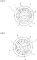
- a circumferential width dimension of the ball collection jig 14 is substantially the same as a circumferential length L 1 of a circumferential gap between the rolling elements 6, 6 located at both circumferential ends thereof in the state where the rolling elements 6, 6 are collected to one circumferential place.
- the circumferential length L 1 of the circumferential gap between the rolling elements 6, 6 located at both the circumferential ends is a circumferential length on a pitch circle C of the rolling elements 6, 6, as shown in FIG. 10 .
- a leading end face (lower end face) of the ball collection jig 14 is configured as an inclined surface (a mountain shape) having a circumferentially central part most protruding and inclined upward toward both circumferential sides thereof.
- the leading end face of the ball collection jig 14 may be configured as an inclined surface (a shape inclined in one direction) having one circumferential end side most protruding and inclined upward toward the other circumferential end side.
- the rolling elements 6, 6 are moved in the rolling element mounting space 7. Thereby, the rolling elements 6, 6 are collected to one circumferential place in the rolling element mounting space 7.
- the ball collection jig 14 is pulled out from the rolling element mounting space 7.
- the conveyance mechanism 11 is moved in a direction (a direction facing toward an upstream side of the assembly line) shown with the arrow A 3 in FIG. 5 along the assembly line, and is thus returned to the original position.
- the ball bearing 1 is conveyed from the ball collection operation position P 1 to the block division operation position P 2 by the conveyance mechanism 11.
- a partially cylindrical positional misalignment prevention member 13a is inserted into the circumferential gap between the rolling elements 6, 6 located at both the circumferential ends, instead of the ball collection jig 14.
- the ball bearing 1 is conveyed from the ball collection operation position P 1 to the block division operation position P 2 .
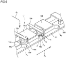
- a support arm 15a is provided between the conveyance arms 12b, 12c of the conveyance mechanism 11, and a leading end portion of the support arm 15a is provided with an annular disk part 16a.
- the annular disk part 16a is configured so that it is located above a part between the leading end portions of the conveyance arms 12b, 12c.
- the positional misalignment prevention member 13a is formed to protrude downward from a lower surface of the annular disk part 16a.
- a circumferential width dimension of the positional misalignment prevention member 13a is substantially the same as the circumferential width dimension of the ball collection jig 14.
- the conveyance mechanism 11 When conveying the ball bearing 1 from the ball collection operation position P 1 to the block division operation position P 2 , the conveyance mechanism 11 is first displaced in the direction of coming close to the operating table 10 with respect to the direction perpendicular to the assembly line and is then displaced downward, as shown with the arrow A 4 in FIG. 6 . Thereby, the leading end portions of the conveyance arms 12b, 12c of the conveyance mechanism 11 are arranged at both sides of the ball bearing 1 placed at the ball collection operation position P 1 (the ball bearing 1 is arranged between the leading end portions of the adjacent conveyance arms 12b, 12c).
- the positional misalignment prevention member 13a is inserted into the circumferential gap, which exists between the rolling elements 6, 6 located at both the circumferential ends of the rolling elements 6, 6 collected to one circumferential place in the rolling element mounting space 7, from above so that the circumferential gap is to be filled.
- the conveyance mechanism 11 is slid in the direction shown with the arrow A 1 in FIG. 6 along the assembly line by a predetermined amount, thereby pushing and moving the outer peripheral surface of the ball bearing 1 by the side surface of the leading end portion of the conveyance arm 12b, which is located upstream of the assembly line, of the adjacent conveyance arms 12b, 12c. Then, the ball bearing 1 is conveyed to the block division operation position P 2 . After conveying the ball bearing 1 to the block division operation position P 2 , the conveyance mechanism 11 is displaced upward, as shown with the arrow A 2 in FIG. 7 , so that the positional misalignment prevention member 13a is pulled out from the circumferential gap.
- conveyance arms 12b, 12c are retreated from both sides of the ball bearing 1, and the conveyance mechanism 11 is further displaced in the direction of separating from the operating table 10 with respect to the direction perpendicular to the assembly line and is thus retreated from the operating table 10.
- a block division process of dividing and arranging the rolling elements 6, 6 collected to one circumferential place in the rolling element mounting space 7 into blocks each including a plurality of rolling elements 6 (a block including three rolling elements 6 and a block including four rolling elements 6, in the shown example) at a plurality of circumferential places in the rolling element mounting space 7 is implemented.
- the block division process is performed by inserting a pair of block division jigs 17, 17 each having a partially cylindrical shape into the rolling element mounting space 7 from above.
- a circumferential width dimension of each of the pair of block division jigs 17, 17 is substantially the same as each of circumferential lengths L 2 , L 2 of circumferential gaps between the rolling elements 6, 6 located at both the circumferential ends of each block in the state where the rolling elements 6, 6 are divided and arranged into blocks each including the plurality of rolling elements at the plurality of circumferential places in the rolling element mounting space 7.
- the rolling elements 6, 6 are divided and arranged into the blocks each including the plurality of rolling elements 6 at the plurality of circumferential places in the rolling element mounting space 7.
- each of the circumferential length L 2 , L 2 of the circumferential gaps between the rolling elements 6, 6 located at both the circumferential ends of each block is a circumferential length on the pitch circle C of the rolling elements 6, 6, as shown in FIG. 11 .
- the circumferential lengths L 2 , L 2 ( ⁇ the circumferential dimensions of the pair of block division jigs 17, 17) of the circumferential gaps between the rolling elements 6, 6 located at both the circumferential ends of each block are the same.
- the circumferential lengths of the respective circumferential gaps may be made to be different from each other.
- a leading end face (lower surface) of one block division jig 17 of the pair of block division jigs 17, 17 is configured as an inclined surface inclined upward from one circumferential side toward the other circumferential side.
- a leading end face (lower surface) of the other block division jig 17 is configured as an inclined surface inclined upward from the other circumferential side toward one circumferential side. Therefore, when the pair of block division jigs 17, 17 is inserted into the rolling element mounting space 7 from above until the leading end portions of the pair of block division jigs 17, 17 protrude downward beyond the lower surface of the operating table 10 through the circular hole 20c, the rolling elements 6, 6 are moved in the rolling element mounting space 7.
- the rolling elements 6, 6 are divided into blocks each including the plurality of rolling elements 6 (the block including three rolling elements 6 and the block including four rolling elements 6, in the shown example) at the plurality of circumferential places in the rolling element mounting space 7.
- the rolling elements are preferably divided into blocks each including the same number of rolling elements 6.
- circumferential phases of the insertion positions of the pair of block division jigs 17, 17 are controlled.
- one or more (in the shown example, one from one circumferential side and two from the other circumferential side) of the rolling elements 6, 6 collected to one circumferential place in the rolling element mounting space 7 are moved from each of both the circumferential sides, so that the rolling elements 6, 6 are divided into the blocks each including the plurality of rolling elements 6.
- the total number of the rolling elements 6, 6 is an even number, the same number of the rolling elements are preferably moved from each of both the circumferential sides.
- one or more of the rolling elements 6, 6 collected to one circumferential place in the rolling element mounting space 7 are moved from each of both the circumferential sides, so that the rolling elements 6, 6 are divided blocks each including the plurality of rolling elements 6. Therefore, it is possible to suppress the force of inserting the pair of block division jigs 17, 17 into the rolling element mounting space 7 from above. In the meantime, when the force of inserting the pair of block division jigs 17, 17 is sufficiently high, some of the rolling elements 6, 6 collected to one circumferential place in the rolling element mounting space 7 may be moved from only one circumferential side to divide the rolling elements 6, 6 into blocks each including the plurality of rolling elements 6.
- the rolling elements 6, 6 are divided into blocks each including the plurality of rolling elements 6 at the plurality of circumferential places in the rolling element mounting space 7, the pair of block division jigs 17, 17 is thereafter pulled out from the rolling element mounting space 7. Also, the conveyance mechanism 11 is moved in the direction shown with the arrow A 3 in FIG. 8 along the assembly line, and is thus returned to the original position thereof.
- the plurality of rolling elements 6, 6 is divided into blocks each including the plurality of rolling elements 6 at the two circumferential places by the pair of block division jigs 17, 17.
- the rolling elements 6, 6 can be divided into the three or more blocks.
- the ball bearing 1 is conveyed from the block division operation position P 2 shown in FIG. 9 to the equal distribution operation position P 3 by the conveyance mechanism 11.
- the positional misalignment prevention members 13b, 13b each having a partially circular arc shape are inserted, instead of the pair of block division jigs 17, 17, into the circumferential gaps between the rolling elements 6, 6, which are located at both the circumferential ends of each block, of the rolling elements 6, 6 divided into blocks each including the plurality of rolling elements at the plurality of circumferential places in the rolling element mounting space 7.
- the ball bearing 1 is conveyed from the block division operation position P 2 to the equal distribution operation position P 3 .
- a support arm 15b is provided between the adjacent conveyance arms 12c, 12d of the conveyance mechanism 11, and a leading end portion of the support arm 15b is provided with an annular disk part 16b.
- the annular disk part 16b is configured to be located above a part between the leading end portions of the conveyance arms 12c, 12d.
- the positional misalignment prevention members 13b, 13b are formed to protrude downward from a plurality of circumferential places (in this example, two places substantially opposite to each other in the radial direction) of an outer peripheral edge portion of a lower surface of the annular disk part 16b.
- a circumferential width dimension of each of the positional misalignment prevention members 13b, 13b is substantially the same as the circumferential width dimension of each of the pair of block division jigs 17, 17.
- the conveyance mechanism 11 When moving the ball bearing 1 from the block division operation position P 2 to the equal distribution operation position P 3 , the conveyance mechanism 11 is first displaced in the direction of coming close to the operating table 10 with respect to the direction perpendicular to the assembly line and is then displaced downward, as shown with the arrow A 4 in FIG. 9 . Thereby, the leading end portions of the conveyance arms 12c, 12d of the conveyance mechanism 11 are arranged at both sides of the ball bearing 1 placed at the block division operation position P 2 (the ball bearing 1 is arranged between the leading end portions of the adjacent conveyance arms 12c, 12d). Also, the positional misalignment prevention members 13b, 13b are inserted into the circumferential gaps, which exist between the rolling elements 6, 6 located at both the circumferential ends of each block, from above so that the respective circumferential gaps are to be filled.
- the conveyance mechanism 11 is slid in the direction shown with the arrow A 1 in FIG. 9 along the assembly line by a predetermined amount. Thereby, the outer peripheral surface of the ball bearing 1 is pushed and moved along the operating table 10 by the side surface of the leading end portion of the conveyance arm 12c, which is located upstream of the assembly line, of the adjacent conveyance arms 12c, 12d, so that the ball bearing 1 is conveyed to the equal distribution operation position P 3 . After conveying the ball bearing 1 to the equal distribution operation position P 3 , the conveyance mechanism 11 is displaced upward, so that the positional misalignment prevention members 13a, 13b are pulled out from the circumferential gaps.
- conveyance arms 12c, 12d are retreated from both sides of the ball bearing 1, and the conveyance mechanism 11 is further displaced in the direction of separating from the operating table 10 with respect to the direction perpendicular to the assembly line and is thus retreated from the operating table 10.
- an equal distribution process of arranging the rolling elements 6, 6, which have been divided into the blocks each including the plurality of rolling elements 6 at the plurality of circumferential places in the rolling element mounting space 7, at equal intervals at a plurality of circumferential places in the rolling element mounting space 7 is implemented.
- the equal distribution process is performed by axially inserting teeth 19, 19 configuring a comb-shaped cylindrical equal distribution jig 18 into the rolling element mounting space 7.
- a circumferential dimension between circumferential side surfaces of the respective teeth 19, 19 is substantially the same as each diameter of the rolling elements 6, 6.
- a leading end face of each of the teeth 19, 19 is configured as an inclined surface (inclined in a mountain shape of which a circumferentially central part most protrudes or inclined upward toward one circumferential side or the other circumferential side) so as to guide the movement of the rolling elements 6, 6 in the rolling element mounting space 7 as the equal distribution jig 18 is inserted into the rolling element mounting space 7. Therefore, when the teeth 19, 19 configuring the equal distribution jig 18 are axially inserted into the rolling element mounting space 7, the rolling elements 6, 6 are moved in the rolling element mounting space 7 with being guided by the leading end faces of the respective teeth 19, 19. Then, as shown in FIG. 2F , the rolling elements are arranged at equal intervals at the plurality of circumferential places in the rolling element mounting space 7.
- the rolling elements 6, 6 are arranged at equal intervals in the circumferential direction, as described above, the teeth 19, 19 of the equal distribution jig 18 are thereafter pulled out from the rolling element mounting space 7. Then, the pair of cage elements 8, 8 is inserted into the rolling element mounting space 7 from both axial sides and is coupled by a plurality of rivets to configure the cage 9 and to rollably keep the rolling elements 6, 6, so that the ball bearing 1 is configured.
- a crown-shaped cage is used as the cage, the crown-shaped cage is inserted from one axial opening of the rolling element mounting space and is incorporated.
- the positional misalignment prevention members 13a, 13b are inserted into the circumferential gaps between the rolling elements 6, 6.
- the rolling elements 6, 6 are prevented from being dispersedly scattered and positionally misaligned. That is, the positions of the rolling elements 6, 6 are restrained so that the rolling elements are not to be moved in the circumferential direction.
- the positional misalignment prevention members 13a, 13b, the ball collection jig 14 and the block division jigs 17, 17 may be inserted into the rolling element mounting space 7 and the circumferential gaps in any vertical direction inasmuch as the direction is the axial direction of the ball bearing 1.
- the insertion directions of the ball collection jig 14 and the positional misalignment prevention member 13a may be opposite to each other, and the ball collection jig 14 may be pulled out from the rolling element mounting space 7 and the positional misalignment prevention member 13a may be simultaneously inserted into the rolling element mounting space 7.
- the ball collection jig 14 is inserted into the rolling element mounting space 7 from below through the circular hole 20a of the operating table 10. Then, in order to convey the ball bearing 1 to the block division operation position P 2 , the conveyance mechanism 11 is displaced downward so as to be moved to a predetermined position. Accompanied by this, the leading end face (the upper end face) of the ball collection jig 14 is pressed by the leading end face (the lower end face) of the positional misalignment prevention member 13a to displace downward the ball collection jig 14, thereby pulling out the ball collection jig from the rolling element mounting space 7 and inserting the positional misalignment prevention member 13a into the rolling element mounting space 7.
- the positional misalignment prevention member 13a is at the same time inserted into the rolling element mounting space 7.
- the insertion directions of the block division jigs 17, 17 and the positional misalignment prevention member 13b, 13b may be opposite to each other, and the block division jigs 17, 17 may be pulled out from the rolling element mounting space 7 and the positional misalignment prevention member 13b, 13b may be simultaneously inserted into the rolling element mounting space 7.
- the rolling elements 6, 6 are arranged at equal intervals in the circumferential direction and the positional misalignment prevention members are then inserted into the circumferential gaps between the respective rolling elements 6, 6.
- the ball bearing 1 may be conveyed to the next operation position, the positional misalignment prevention members may be removed, and the cage 9 may be incorporated.
- the present invention is applied to the assembling operation of the radial ball bearing of the single-row deep groove ball type.
- the present invention is not limited to the ball bearing of the single-row deep groove ball type, and can also be applied to the radial rolling bearing such as an angular ball bearing, a tapered roller bearing, a cylindrical roller bearing and the like.
- the method of conveying the rolling bearing along the assembly line is not limited to the method of using the conveyance mechanism 11, and the diverse methods known in the related art can also be used.
- the rolling bearing can be conveyed by a variety of conveyors or a hanging-down or hanging-up type conveyance device configured to sandwich and convey the rolling bearing by a pair of arms.
- the method of collecting the rolling elements to one circumferential place in the rolling element mounting space, the method of dividing and arranging the rolling elements into blocks each including the plurality of rolling elements, and the method of arranging the rolling elements at equal intervals are not limited to the above-described methods, and the diverse methods known in the related art can also be used.
- the rolling elements balls
- the rolling elements may be collected to one circumferential place in the rolling element mounting space and divided into blocks each including the plurality of rolling elements by using a pair of arms.
- the ball collection operation, the block division operation, and the equal distribution operation are individually implemented at the operation positions P 1 to P 3 .
- the ball collection operation and the block division operation may be implemented at one operation position.
- the rolling bearing is conveyed to the next operation position with the positional misalignment prevention member being inserted in the circumferential gap between the rolling elements located at both the circumferential ends of each block and the equal distribution operation is then implemented.
- the block division operation and the equal distribution operation may be implemented at one operation position.
- the rolling bearing is conveyed to the next operation position with the positional misalignment prevention member being inserted in the circumferential gap existing at both the circumferential ends of the rolling elements collected to one circumferential place, and the block division operation and the equal distribution operation are implemented at one operation position. Also, after the ball collection operation is implemented, the rolling bearing may be conveyed to the next operation position with the positional misalignment prevention member being inserted in the circumferential gap existing at both the circumferential ends of the rolling elements collected to one circumferential place, and the block collection operation may be implemented without performing the ball division operation.
- the method of equally distributing rolling elements of a rolling bearing can be applied to not only the rolling bearing but also a variety of machines (including an instrument of which power is to be manually fed).
- the present invention can be widely applied to a vehicle including diverse mechanisms such as an electric power steering device, a machine tool, a home device and the like.
- the machine, the vehicle and the like obtained in this way can be configured at lower cost and with higher quality, as compared to the related art.
Landscapes
- Engineering & Computer Science (AREA)
- General Engineering & Computer Science (AREA)
- Mechanical Engineering (AREA)
- Mounting Of Bearings Or Others (AREA)
- Rolling Contact Bearings (AREA)
- Automatic Assembly (AREA)
- Support Of The Bearing (AREA)
Abstract


Description
- The present invention relates to a method of equally distributing rolling elements of a rolling bearing, and manufacturing methods of a rolling bearing, a machine and a vehicle.
- For example, a rolling bearing such as a ball bearing 1 shown in
FIG. 1 is incorporated to a rotation support part of a variety of mechanical devices. When assembling the ball bearing 1, a plurality ofrolling elements inner ring 2 and anouter ring raceway 5 provided on an inner peripheral surface of anouter ring 4, and therolling elements cage elements element mounting space 7 between the inner ring raceway 3 and theouter ring raceway 5, and is coupled by a plurality of rivets to configure acage 9, so that therolling elements - In the state where the plurality of
rolling elements element mounting space 7, therolling elements element mounting space 7.Patent Document 1 discloses an example of a method of arranging therolling elements - According to the method disclosed in
Patent Document 1, since it is possible to shorten axial lengths of teeth (operation arrows) configuring the ball distribution jig, it is possible to prevent wear and deformation of the ball distribution jig. Also, since it is possible to reduce an insertion load upon the insertion of the ball distribution jig into the rolling element mounting space, it is possible to efficiently prevent the damage of the rolling elements and the deformation of the ball distribution jig. - Patent Document 1:
JP-A-2008-200789 - According to the method disclosed in
Patent Document 1, there is a room for further improvement, from a standpoint of improving productivity (assemblability) of the rolling bearing. That is, according to the method disclosed inPatent Document 1, on an assembly line of the rolling bearing, it is necessary to perform all of the operation (ball collection operation) of collecting the rolling elements to one circumferential place in the rolling element mounting space, the operation (block division operation) of dividing the rolling elements into blocks each including the plurality of rolling elements, and the operation (equal distribution operation) of arranging the rolling elements at equal intervals at the plurality of circumferential places, at one operation position (in the same assembly process). For this reason, an operation amount in the process of arranging the rolling elements unequally spaced in the rolling element mounting space, at equal intervals increases, and the corresponding process becomes a bottle neck on the assembly line of the rolling bearing, so that the assemblability of the rolling bearing may be deteriorated. - The present invention has been made in view of the above situations, and an object thereof is to improve a method of equally distributing rolling elements of a rolling bearing, and manufacturing methods of a rolling bearing, a machine, and a vehicle capable of improving assemblability of a rolling bearing.
- A method of equally distributing rolling elements of a rolling bearing of the present invention is a method for arranging a plurality of rolling elements at equal intervals at a plurality of circumferential places in a rolling element mounting space between an inner ring raceway provided on an outer peripheral surface of an inner ring and an outer ring raceway provided on an inner peripheral surface of an outer ring.
- In a first aspect of the present invention, there is provided a method of equally distributing rolling elements of a rolling bearing including collecting the rolling elements to one circumferential place in the rolling element mounting space, and conveying the rolling bearing to a next process in a state where a positional misalignment prevention member is inserted in a circumferential gap existing between the rolling elements, which are located at both circumferential ends, at both the circumferential ends of the rolling elements collected to one circumferential place in the rolling element mounting space.
- In a second aspect of the present invention, there is provided a method of equally distributing rolling elements of a rolling bearing including dividing the rolling elements into blocks each including a plurality of rolling elements and arranging the same at a plurality of circumferential places in the rolling element mounting space, and conveying the rolling bearing to a next process in a state where a positional misalignment prevention member is inserted in a circumferential gap existing between the rolling elements located at both circumferential ends of each block.
- When implementing the method of equally distributing rolling elements of a rolling bearing of the present invention, the first aspect and the second aspect may be implemented at the same time. In the meantime, the positional misalignment prevention member that is to be used in the first aspect and the positional misalignment prevention member that is to be used in the second aspect have different shapes.
- The present invention can be preferably applied to a ball bearing in which balls are used as the rolling elements. Alternatively, the present invention can also be applied to a cylindrical roller bearing in which a cylindrical roller (including a needle) is used as the rolling element or a tapered roller bearing in which a tapered roller is used as the rolling element.
- Also, the method of equally distributing rolling elements of a rolling bearing can be applied to a manufacturing method of a rolling bearing, a manufacturing method of a machine, and a manufacturing method of a vehicle.
- According to the method of equally distributing rolling elements of a rolling bearing, and the manufacturing methods of the rolling bearing, the machine and the vehicle of the present invention, it is possible to easily improve the assemblability of the rolling bearing.
-
-
FIG. 1 is a partially cut perspective view depicting a ball bearing, which is a target of an example of an embodiment of the present invention. -
FIGS. 2A to 2F are perspective views depicting the example of the embodiment of the present invention, in process order with the ball bearing being taken out. -
FIG. 3 is a perspective view depicting an aspect in which the ball bearing is conveyed to a ball collection operation position, in the example of the embodiment of the present invention. -
FIG. 4 is a perspective view depicting an aspect in which a conveyance mechanism is retreated after conveying the ball bearing to the ball collection operation position. -
FIG. 5 is a perspective view depicting an aspect in which a ball collection process is implemented. -
FIG. 6 is a perspective view depicting an aspect in which the ball bearing is conveyed to a block division operation position with a positional misalignment prevention member being inserted in a circumferential gap existing between rolling elements. -
FIG. 7 is a perspective view depicting an aspect in which the conveyance mechanism is retreated after the ball bearing is conveyed to the block division operation position. -
FIG. 8 is a perspective view depicting an aspect in which a block division process is implemented. -
FIG. 9 is a perspective view depicting an aspect in which the ball bearing is conveyed to an equal distribution operation position with the positional misalignment prevention member being inserted in the circumferential gap existing between the rolling elements. -
FIG. 10 is a plan view of the ball bearing, depicting a state in which the rolling elements are collected to one circumferential place in a rolling element mounting space. -
FIG. 11 is a plan view of the ball bearing, depicting a state in which the rolling elements are divided into a plurality of blocks at a plurality of circumferential places in the rolling element mounting space. -
FIGS. 12A and 12B are plan views for illustrating a method of dividing the rolling elements, which have been collected to one circumferential place in the rolling element mounting space, into blocks each including the plurality of rolling elements. -
FIGS. 13A and 13B are plan view depicting another example of the method of dividing the rolling elements, which have been collected to one circumferential place in the rolling element mounting space, into blocks each including the plurality of rolling elements. -
FIGS. 1 to 13B depict an example of an embodiment of the present invention. As shown inFIG. 1 , a ball bearing 1, which is a target of the example, is configured by mounting a plurality of rolling elements (balls) 6, 6 between aninner ring 2 and anouter ring 4 arranged coaxially with each other. Theinner ring 2 has an inner ring raceway 3 provided at an axially intermediate part of an outer peripheral surface thereof. Theouter ring 4 has anouter ring raceway 5 provided at an axially intermediate part of an inner peripheral surface thereof. Therolling elements outer ring raceway 5 with being held by acage 9. Thecage 9 is a corrugated cage and has a pair ofcage elements - The ball bearing 1 as described above is assembled by a transfer machine in which a series of assembling operations are incorporated in one assembly line. Specifically, a plurality of operation positions P0 to P3... is provided at predetermined intervals along the assembly line on an operating table 10. While conveying the ball bearing 1 put at each of the operation positions P0 to P3... to the next operation positions P1 to P3... by a
conveyance mechanism 11, each process of the assembling operation is implemented at each of the operation positions P0 to P3..., so that the ball bearing 1 is assembled. The parts, which match the respective operation positions P0 to P3..., of the operating table 10 are formed withcircular holes 20a to 20d vertically penetrating the operating table 10. An inner diameter of each of thecircular holes 20a to 20d is made smaller than an outer diameter of theouter ring 4 and larger than an inner diameter of the outer ring 4 (a cylindrical surface existing at a part deviating from the outer ring raceway 5). Theconveyance mechanism 11 has a plurality ofconveyance arms 12a to 12d provided at predetermined intervals along the assembly line. When conveying the ball bearing 1, theconveyance mechanism 11 is first displaced in a direction of coming close to the operating table 10. Thereby, the ball bearing 1 is arranged between leading end portions of theconveyance arms 12a to 12d adjacent to each other. Then, theconveyance mechanism 11 is slid along the assembly line by a predetermined amount, so that the outer peripheral surface of (theouter ring 4 of) the ball bearing 1 is pushed and moved by a side surface of the leading end portion of each of theconveyance arms 12a to 12d, which is located upstream of the assembly line, of theadjacent conveyance arms 12a to 12d. Thereby, the ball bearing 1 is conveyed to the next operation positions P1 to P3.... InFIGS. 2A to 9 , regarding the series of assembling operations of assembling theball bearing 1, only parts relating to each process for arranging the rollingelements element mounting space 7 between the inner ring raceway 3 and theouter ring raceway 5, at equal intervals are shown. InFIGS. 2A to 9 , for convenience sake, only oneball bearing 1 is shown. Actually, however, theball bearing 1 is respectively arranged at each of the plurality of operation positions P0 to P3..., and the assembling process corresponding to the operation positions P0 to P3... is implemented for each of theball bearings 1. - In this example, the rolling
elements element mounting space 7, and the rollingbearing 1 is placed at an initial position P0. In this state, the rollingelements element mounting space 7. Then, at a ball collection operation position P1, the rollingelements element mounting space 7 are collected to a position of one circumferential place in the rollingelement mounting space 7. Then, theball bearing 1 is conveyed (moved) to a block division operation position P2, and the rollingelements element mounting space 7. Thereafter, theball bearing 1 is conveyed to an equal distribution operation position P3, and the rollingelements element mounting space 7. Particularly, in this example, when conveying theball bearing 1 from the ball collection operation position P1 to the block division operation position P2, and when conveying theball bearing 1 from the block division operation position P2 to the equal distribution operation position P3, positionalmisalignment prevention members rolling elements elements elements element mounting space 7 at equal intervals is described in detail with reference toFIGS. 2A to 9 . - When assembling the
ball bearing 1, theinner ring 2 is first arranged at a radially inner side of theouter ring 4 in a state where a central axis of theinner ring 2 is offset relative to a central axis of theouter ring 4. In this state, the plurality of (seven, in the example ofFIGS. 2A to 2F ) rollingelements outer ring raceway 5 into the substantially partially cylindrical space. Then, the central axis of theinner ring 2 and the central axis of theouter ring 4 are made to coincide with each other. In this stage, the rollingelements element mounting space 7 between the inner ring raceway 3 and theouter ring raceway 5. Theball bearing 1 of which the rollingelements element mounting space 7 is placed at the initial position P0 on the operating table 10. - Then, the
ball bearing 1 placed at the initial position P0 is conveyed to the ball collection operation position P1 on the operating table 10 by theconveyance mechanism 11. To this end, theconveyance mechanism 11 is displaced in the direction of coming close to the operating table 10, and the leading end portions of theadjacent conveyance arms ball bearing 1 placed at the initial position P0 (theball bearing 1 is arranged between the leading end portions of theadjacent conveyance arms conveyance mechanism 11 is slid in a direction shown with the arrow A1 inFIG. 3 (a direction facing toward a downstream side of the assembly line) along the assembly line by a predetermined amount, thereby pushing and moving the outer peripheral surface of theball bearing 1 by the side surface of the leading end portion of theconveyance arms 12a, which is located upstream of the assembly line, of theadjacent conveyance arms ball bearing 1 is conveyed to the ball collection operation position P1. After conveying theball bearing 1 to the ball collection operation position P1, as shown with the arrow A2 inFIG. 4 , theconveyance mechanism 11 is displaced upward and theconveyance arms ball bearing 1. Thereafter, theconveyance mechanism 11 is further displaced in a direction of separating from the operating table 10 with respect to a direction perpendicular to the assembly line and is thus retreated from the operating table 10. - Then, a ball collection process of collecting the rolling
elements element mounting space 7 of theball bearing 1 to one circumferential place in the rollingelement mounting space 7 is implemented. As shown inFIGS. 2A and5 , the ball collection process is performed by inserting a partially cylindricalball collection jig 14 into the rollingelement mounting space 7 in the axial direction (from above, in the shown example). A circumferential width dimension of theball collection jig 14 is substantially the same as a circumferential length L1 of a circumferential gap between therolling elements elements elements rolling elements elements FIG. 10 . A leading end face (lower end face) of theball collection jig 14 is configured as an inclined surface (a mountain shape) having a circumferentially central part most protruding and inclined upward toward both circumferential sides thereof. In addition to the mountain shape, the leading end face of theball collection jig 14 may be configured as an inclined surface (a shape inclined in one direction) having one circumferential end side most protruding and inclined upward toward the other circumferential end side. In any shape, when theball collection jig 14 is inserted into the rollingelement mounting space 7 from above until the leading end portion of theball collection jig 14 protrudes downward beyond a lower surface of the operating table 10 through thecircular hole 20b, the rollingelements element mounting space 7. Thereby, the rollingelements element mounting space 7. When the rollingelements element mounting space 7, theball collection jig 14 is pulled out from the rollingelement mounting space 7. Theconveyance mechanism 11 is moved in a direction (a direction facing toward an upstream side of the assembly line) shown with the arrow A3 inFIG. 5 along the assembly line, and is thus returned to the original position. - Subsequently, the
ball bearing 1 is conveyed from the ball collection operation position P1 to the block division operation position P2 by theconveyance mechanism 11. In this example, at both the circumferential ends of the rollingelements element mounting space 7, a partially cylindrical positionalmisalignment prevention member 13a is inserted into the circumferential gap between therolling elements ball collection jig 14. In this state, theball bearing 1 is conveyed from the ball collection operation position P1 to the block division operation position P2. To this end, asupport arm 15a is provided between theconveyance arms conveyance mechanism 11, and a leading end portion of thesupport arm 15a is provided with anannular disk part 16a. Theannular disk part 16a is configured so that it is located above a part between the leading end portions of theconveyance arms misalignment prevention member 13a is formed to protrude downward from a lower surface of theannular disk part 16a. A circumferential width dimension of the positionalmisalignment prevention member 13a is substantially the same as the circumferential width dimension of theball collection jig 14. - When conveying the
ball bearing 1 from the ball collection operation position P1 to the block division operation position P2, theconveyance mechanism 11 is first displaced in the direction of coming close to the operating table 10 with respect to the direction perpendicular to the assembly line and is then displaced downward, as shown with the arrow A4 inFIG. 6 . Thereby, the leading end portions of theconveyance arms conveyance mechanism 11 are arranged at both sides of theball bearing 1 placed at the ball collection operation position P1 (theball bearing 1 is arranged between the leading end portions of theadjacent conveyance arms misalignment prevention member 13a is inserted into the circumferential gap, which exists between therolling elements elements element mounting space 7, from above so that the circumferential gap is to be filled. - Then, the
conveyance mechanism 11 is slid in the direction shown with the arrow A1 inFIG. 6 along the assembly line by a predetermined amount, thereby pushing and moving the outer peripheral surface of theball bearing 1 by the side surface of the leading end portion of theconveyance arm 12b, which is located upstream of the assembly line, of theadjacent conveyance arms ball bearing 1 is conveyed to the block division operation position P2. After conveying theball bearing 1 to the block division operation position P2, theconveyance mechanism 11 is displaced upward, as shown with the arrow A2 inFIG. 7 , so that the positionalmisalignment prevention member 13a is pulled out from the circumferential gap. Also, theconveyance arms ball bearing 1, and theconveyance mechanism 11 is further displaced in the direction of separating from the operating table 10 with respect to the direction perpendicular to the assembly line and is thus retreated from the operating table 10. - Then, a block division process of dividing and arranging the rolling
elements element mounting space 7 into blocks each including a plurality of rolling elements 6 (a block including threerolling elements 6 and a block including fourrolling elements 6, in the shown example) at a plurality of circumferential places in the rollingelement mounting space 7 is implemented. As shown inFIGS. 2C and8 , the block division process is performed by inserting a pair of block division jigs 17, 17 each having a partially cylindrical shape into the rollingelement mounting space 7 from above. A circumferential width dimension of each of the pair of block division jigs 17, 17 is substantially the same as each of circumferential lengths L2, L2 of circumferential gaps between therolling elements elements element mounting space 7. The rollingelements elements 6 at the plurality of circumferential places in the rollingelement mounting space 7. In this state, each of the circumferential length L2, L2 of the circumferential gaps between therolling elements elements FIG. 11 . In the shown example, the circumferential lengths L2, L2 (≒ the circumferential dimensions of the pair of block division jigs 17, 17) of the circumferential gaps between therolling elements block division jig 17 of the pair of block division jigs 17, 17 is configured as an inclined surface inclined upward from one circumferential side toward the other circumferential side. Also, a leading end face (lower surface) of the otherblock division jig 17 is configured as an inclined surface inclined upward from the other circumferential side toward one circumferential side. Therefore, when the pair of block division jigs 17, 17 is inserted into the rollingelement mounting space 7 from above until the leading end portions of the pair of block division jigs 17, 17 protrude downward beyond the lower surface of the operating table 10 through thecircular hole 20c, the rollingelements element mounting space 7. Thereby, the rollingelements rolling elements 6 and the block including fourrolling elements 6, in the shown example) at the plurality of circumferential places in the rollingelement mounting space 7. When a total number of the rollingelements rolling elements 6. - In this example, circumferential phases of the insertion positions of the pair of block division jigs 17, 17 are controlled. Thereby, as shown in
FIGS. 12A to 12B , one or more (in the shown example, one from one circumferential side and two from the other circumferential side) of the rollingelements element mounting space 7 are moved from each of both the circumferential sides, so that the rollingelements elements 6. When the total number of the rollingelements element mounting space 7 from above is suppressed. That is, as shown inFIGS. 13A to 13B , when some of the rollingelements element mounting space 7 are moved from only one circumferential side to divide the rollingelements elements 6, it is necessary to move the rollingelements elements element mounting space 7 from above is increased. In contrast, in this example, one or more of the rollingelements element mounting space 7 are moved from each of both the circumferential sides, so that the rollingelements elements 6. Therefore, it is possible to suppress the force of inserting the pair of block division jigs 17, 17 into the rollingelement mounting space 7 from above. In the meantime, when the force of inserting the pair of block division jigs 17, 17 is sufficiently high, some of the rollingelements element mounting space 7 may be moved from only one circumferential side to divide the rollingelements elements 6. - When the rolling
elements elements 6 at the plurality of circumferential places in the rollingelement mounting space 7, the pair of block division jigs 17, 17 is thereafter pulled out from the rollingelement mounting space 7. Also, theconveyance mechanism 11 is moved in the direction shown with the arrow A3 inFIG. 8 along the assembly line, and is thus returned to the original position thereof. - In the shown example, the plurality of rolling
elements elements 6 at the two circumferential places by the pair of block division jigs 17, 17. However, when three or more of the block division jigs are used, the rollingelements - Subsequently, the
ball bearing 1 is conveyed from the block division operation position P2 shown inFIG. 9 to the equal distribution operation position P3 by theconveyance mechanism 11. In this example, the positionalmisalignment prevention members rolling elements elements element mounting space 7. In this state, theball bearing 1 is conveyed from the block division operation position P2 to the equal distribution operation position P3. To this end, asupport arm 15b is provided between theadjacent conveyance arms conveyance mechanism 11, and a leading end portion of thesupport arm 15b is provided with anannular disk part 16b. Theannular disk part 16b is configured to be located above a part between the leading end portions of theconveyance arms misalignment prevention members annular disk part 16b. A circumferential width dimension of each of the positionalmisalignment prevention members - When moving the
ball bearing 1 from the block division operation position P2 to the equal distribution operation position P3, theconveyance mechanism 11 is first displaced in the direction of coming close to the operating table 10 with respect to the direction perpendicular to the assembly line and is then displaced downward, as shown with the arrow A4 inFIG. 9 . Thereby, the leading end portions of theconveyance arms conveyance mechanism 11 are arranged at both sides of theball bearing 1 placed at the block division operation position P2 (theball bearing 1 is arranged between the leading end portions of theadjacent conveyance arms misalignment prevention members rolling elements - Then, the
conveyance mechanism 11 is slid in the direction shown with the arrow A1 inFIG. 9 along the assembly line by a predetermined amount. Thereby, the outer peripheral surface of theball bearing 1 is pushed and moved along the operating table 10 by the side surface of the leading end portion of theconveyance arm 12c, which is located upstream of the assembly line, of theadjacent conveyance arms ball bearing 1 is conveyed to the equal distribution operation position P3. After conveying theball bearing 1 to the equal distribution operation position P3, theconveyance mechanism 11 is displaced upward, so that the positionalmisalignment prevention members conveyance arms ball bearing 1, and theconveyance mechanism 11 is further displaced in the direction of separating from the operating table 10 with respect to the direction perpendicular to the assembly line and is thus retreated from the operating table 10. - Subsequently, an equal distribution process of arranging the rolling
elements elements 6 at the plurality of circumferential places in the rollingelement mounting space 7, at equal intervals at a plurality of circumferential places in the rollingelement mounting space 7 is implemented. As shown inFIG. 2E , the equal distribution process is performed by axially insertingteeth equal distribution jig 18 into the rollingelement mounting space 7. A circumferential dimension between circumferential side surfaces of therespective teeth elements teeth elements element mounting space 7 as theequal distribution jig 18 is inserted into the rollingelement mounting space 7. Therefore, when theteeth equal distribution jig 18 are axially inserted into the rollingelement mounting space 7, the rollingelements element mounting space 7 with being guided by the leading end faces of therespective teeth FIG. 2F , the rolling elements are arranged at equal intervals at the plurality of circumferential places in the rollingelement mounting space 7. - When the rolling
elements teeth equal distribution jig 18 are thereafter pulled out from the rollingelement mounting space 7. Then, the pair ofcage elements element mounting space 7 from both axial sides and is coupled by a plurality of rivets to configure thecage 9 and to rollably keep therolling elements ball bearing 1 is configured. When a crown-shaped cage is used as the cage, the crown-shaped cage is inserted from one axial opening of the rolling element mounting space and is incorporated. - According to the example as described above, when conveying the ball bearing from the ball collection operation position P1 to the block division operation position P2, and when conveying the ball bearing from the block division operation position P2 to the equal distribution operation position P3, the positional
misalignment prevention members rolling elements elements elements elements element mounting space 7, the operation (the ball division operation) of dividing the rolling elements into blocks each including the plurality of rolling elements and the operation (the equal distribution operation) of arranging the rolling elements at equal intervals at the plurality of circumferential places, at the separate operation positions P1 to P3. Therefore, unlikePatent Document 1, it is possible to prevent the situation where an operation amount in the process of arranging the rolling elements unequally spaced in the rolling element mounting space, at equal intervals increases and the corresponding process becomes a bottle neck on the assembly line of the rolling bearing, so that it is possible to improve the assemblability of theball bearing 1. - When implementing the embodiment described above, the positional
misalignment prevention members ball collection jig 14 and the block division jigs 17, 17 may be inserted into the rollingelement mounting space 7 and the circumferential gaps in any vertical direction inasmuch as the direction is the axial direction of theball bearing 1. For example, the insertion directions of theball collection jig 14 and the positionalmisalignment prevention member 13a may be opposite to each other, and theball collection jig 14 may be pulled out from the rollingelement mounting space 7 and the positionalmisalignment prevention member 13a may be simultaneously inserted into the rollingelement mounting space 7. Specifically, for example, when implementing the ball collection process, theball collection jig 14 is inserted into the rollingelement mounting space 7 from below through thecircular hole 20a of the operating table 10. Then, in order to convey theball bearing 1 to the block division operation position P2, theconveyance mechanism 11 is displaced downward so as to be moved to a predetermined position. Accompanied by this, the leading end face (the upper end face) of theball collection jig 14 is pressed by the leading end face (the lower end face) of the positionalmisalignment prevention member 13a to displace downward theball collection jig 14, thereby pulling out the ball collection jig from the rollingelement mounting space 7 and inserting the positionalmisalignment prevention member 13a into the rollingelement mounting space 7. In this way, while pulling out theball collection jig 14 from the rollingelement mounting space 7, the positionalmisalignment prevention member 13a is at the same time inserted into the rollingelement mounting space 7. Thereby, after theball collection jig 14 is pulled out until the positionalmisalignment prevention member 13a is inserted, it is possible to securely prevent therolling elements misalignment prevention member element mounting space 7 and the positionalmisalignment prevention member element mounting space 7. - In the equal distribution process, the rolling
elements respective rolling elements ball bearing 1 may be conveyed to the next operation position, the positional misalignment prevention members may be removed, and thecage 9 may be incorporated. - In the example of the embodiment, the present invention is applied to the assembling operation of the radial ball bearing of the single-row deep groove ball type. However, the present invention is not limited to the ball bearing of the single-row deep groove ball type, and can also be applied to the radial rolling bearing such as an angular ball bearing, a tapered roller bearing, a cylindrical roller bearing and the like.
- The method of conveying the rolling bearing along the assembly line is not limited to the method of using the
conveyance mechanism 11, and the diverse methods known in the related art can also be used. For example, the rolling bearing can be conveyed by a variety of conveyors or a hanging-down or hanging-up type conveyance device configured to sandwich and convey the rolling bearing by a pair of arms. - The method of collecting the rolling elements to one circumferential place in the rolling element mounting space, the method of dividing and arranging the rolling elements into blocks each including the plurality of rolling elements, and the method of arranging the rolling elements at equal intervals are not limited to the above-described methods, and the diverse methods known in the related art can also be used. For example, like the method disclosed in
Patent Document 1, the rolling elements (balls) may be collected to one circumferential place in the rolling element mounting space and divided into blocks each including the plurality of rolling elements by using a pair of arms. - In the example of the embodiment, the ball collection operation, the block division operation, and the equal distribution operation are individually implemented at the operation positions P1 to P3. However, the ball collection operation and the block division operation may be implemented at one operation position. In this case, after the ball collection operation and the block division operation are implemented at one operation position, the rolling bearing is conveyed to the next operation position with the positional misalignment prevention member being inserted in the circumferential gap between the rolling elements located at both the circumferential ends of each block and the equal distribution operation is then implemented. Also, the block division operation and the equal distribution operation may be implemented at one operation position. In this case, after the ball collection operation is implemented, the rolling bearing is conveyed to the next operation position with the positional misalignment prevention member being inserted in the circumferential gap existing at both the circumferential ends of the rolling elements collected to one circumferential place, and the block division operation and the equal distribution operation are implemented at one operation position. Also, after the ball collection operation is implemented, the rolling bearing may be conveyed to the next operation position with the positional misalignment prevention member being inserted in the circumferential gap existing at both the circumferential ends of the rolling elements collected to one circumferential place, and the block collection operation may be implemented without performing the ball division operation.
- The method of equally distributing rolling elements of a rolling bearing can be applied to not only the rolling bearing but also a variety of machines (including an instrument of which power is to be manually fed). For example, the present invention can be widely applied to a vehicle including diverse mechanisms such as an electric power steering device, a machine tool, a home device and the like. The machine, the vehicle and the like obtained in this way can be configured at lower cost and with higher quality, as compared to the related art.
- The subject application is based on Japanese Patent Application No.
2017-389 filed on January 5, 2017 -
- 1: ball bearing
- 2: inner ring
- 3: inner ring raceway
- 4: outer ring
- 5: outer ring raceway
- 6: rolling element
- 7: rolling element mounting space
- 9: cage
- 13a, 13b: positional misalignment prevention member
Claims (6)
- A method of equally distributing rolling elements of a rolling bearing, the method for arranging a plurality of rolling elements at equal intervals at a plurality of circumferential places in a rolling element mounting space between an inner ring raceway provided on an outer peripheral surface of an inner ring and an outer ring raceway provided on an inner peripheral surface of an outer ring,
wherein the method comprises:collecting the rolling elements to one circumferential place in the rolling element mounting space; andconveying the rolling bearing to a next process in a state where a positional misalignment prevention member is inserted in a circumferential gap existing between the rolling elements, which are located at both circumferential ends, at both the circumferential ends of the rolling elements collected to one circumferential place in the rolling element mounting space. - A method of equally distributing rolling elements of a rolling bearing, the method for arranging a plurality of rolling elements at equal intervals at a plurality of circumferential places in a rolling element mounting space between an inner ring raceway provided on an outer peripheral surface of an inner ring and an outer ring raceway provided on an inner peripheral surface of an outer ring,
wherein the method comprises:dividing the rolling elements into blocks each including a plurality of rolling elements and arranging the blocks at a plurality of circumferential places in the rolling element mounting space; andconveying the rolling bearing to a next process in a state where a positional misalignment prevention member is inserted in a circumferential gap existing between the rolling elements located at both circumferential ends of each block. - The method of equally distributing rolling elements of the rolling bearing according to claim 1 or 2,
wherein the rolling element is a ball. - A manufacturing method of a rolling bearing comprising using the method of equally distributing rolling elements of the rolling bearing according to any one of claims 1 to 3.
- A manufacturing method of a machine comprising using the method of equally distributing rolling elements of the rolling bearing according to any one of claims 1 to 3.
- A manufacturing method of a vehicle comprising using the method of equally distributing rolling elements of the rolling bearing according to any one of claims 1 to 3.
Applications Claiming Priority (2)
| Application Number | Priority Date | Filing Date | Title |
|---|---|---|---|
| JP2017000389 | 2017-01-05 | ||
| PCT/JP2018/000005 WO2018128174A1 (en) | 2017-01-05 | 2018-01-04 | Rolling body uniform arrangement method for rolling bearing, rolling bearing, machine, and vehicle production method |
Publications (3)
| Publication Number | Publication Date |
|---|---|
| EP3483462A1 true EP3483462A1 (en) | 2019-05-15 |
| EP3483462A4 EP3483462A4 (en) | 2019-09-18 |
| EP3483462B1 EP3483462B1 (en) | 2023-05-10 |
Family
ID=62791280
Family Applications (1)
| Application Number | Title | Priority Date | Filing Date |
|---|---|---|---|
| EP18736129.0A Active EP3483462B1 (en) | 2017-01-05 | 2018-01-04 | Rolling body uniform arrangement method for rolling bearing |
Country Status (8)
| Country | Link |
|---|---|
| US (1) | US10240639B2 (en) |
| EP (1) | EP3483462B1 (en) |
| JP (2) | JP6358413B1 (en) |
| KR (1) | KR20190087624A (en) |
| CN (1) | CN110382894B (en) |
| MY (1) | MY196274A (en) |
| SG (1) | SG11201906137TA (en) |
| WO (1) | WO2018128174A1 (en) |
Cited By (2)
| Publication number | Priority date | Publication date | Assignee | Title |
|---|---|---|---|---|
| CN109296655A (en) * | 2018-09-30 | 2019-02-01 | 安徽工程大学 | Bearing assembly equipment integrating ball separation and ball fixing functions and its use method |
| EP4335582B1 (en) * | 2022-06-17 | 2026-03-18 | NSK Ltd. | Ball placement method for ball bearing, ball bearing manufacturing method and manufacturing device, and machine and vehicle manufacturing method |
Families Citing this family (12)
| Publication number | Priority date | Publication date | Assignee | Title |
|---|---|---|---|---|
| JP7159782B2 (en) * | 2018-10-18 | 2022-10-25 | 日本精工株式会社 | Conveying device and method for ring-shaped member, rolling bearing, machine, and manufacturing method for vehicle |
| CN110821967B (en) * | 2019-11-15 | 2021-07-23 | 湖南美蓓达科技股份有限公司 | A ball equalizing device for miniature bearings |
| CN111140599B (en) * | 2019-12-25 | 2024-05-03 | 浙江德清富源智能装备科技有限公司 | High-precision ball separating device and separating method for ball bearing |
| DE102020200086A1 (en) * | 2020-01-07 | 2021-07-08 | Aktiebolaget Skf | Transport securing unit, method for attaching a transport securing unit and method for assembly |
| JP7404904B2 (en) * | 2020-02-03 | 2023-12-26 | 日本精工株式会社 | Methods for manufacturing rolling bearings, and methods for manufacturing machines and vehicles |
| CN111156259A (en) * | 2020-02-05 | 2020-05-15 | 王录红 | Steel ball positioning mechanism based on semi-automatic assembly of ball bearing |
| CN112081819A (en) * | 2020-10-15 | 2020-12-15 | 慈溪市新中天轴承有限公司 | Deep groove ball bearing and preparation process thereof |
| CN112296636B (en) * | 2020-11-02 | 2022-06-10 | 深圳市伙伴气动精密机械有限公司 | Rolling device for automatic roller pressing |
| CN112456074B (en) * | 2020-11-25 | 2022-10-28 | 合肥迈亚家具有限公司 | End cover feeding equipment |
| WO2023243148A1 (en) * | 2022-06-17 | 2023-12-21 | 日本精工株式会社 | Ball placement method for ball bearing, ball bearing manufacturing method and manufacturing device, and machine and vehicle manufacturing method |
| KR102722084B1 (en) * | 2024-05-28 | 2024-10-25 | 주식회사 대신캐스터 | Automatic grease application and bearing ball insertion device |
| CN119508375B (en) * | 2025-01-20 | 2025-04-18 | 江苏福依特机械制造有限公司 | A ball filler for assembling a double-row ball slewing bearing |
Family Cites Families (21)
| Publication number | Priority date | Publication date | Assignee | Title |
|---|---|---|---|---|
| US2931095A (en) * | 1956-12-13 | 1960-04-05 | Sheffield Corp | Assembly apparatus |
| US3079678A (en) * | 1956-12-14 | 1963-03-05 | Sheffield Corp | Assembly apparatus |
| US3148437A (en) * | 1963-04-30 | 1964-09-15 | Skf Ind Inc | Method and apparatus for assembling rolling bearings |
| US3135041A (en) * | 1963-06-27 | 1964-06-02 | Knobel Max | Apparatus for assembling ball bearings |
| US3340590A (en) * | 1965-03-01 | 1967-09-12 | Rehnberg Jacobson Mfg Co Inc | Ball bearing separator |
| US3382016A (en) * | 1965-11-01 | 1968-05-07 | Roller Bearing Co Of America | Arrangement of tandem rollers in a roller bearing and method of assembling same |
| JPS52114843A (en) * | 1976-03-22 | 1977-09-27 | Korona Denshi Kk | Apparatus for evenly distributing balls |
| JPS5711701Y2 (en) * | 1977-05-09 | 1982-03-08 | ||
| JPS58196939A (en) * | 1982-05-11 | 1983-11-16 | Ntn Toyo Bearing Co Ltd | Method for arranging balls uniformly and its device |
| JPH02266113A (en) * | 1989-04-06 | 1990-10-30 | Nobuo Takada | Ball distribution |
| GB2240370B (en) * | 1990-01-25 | 1994-11-23 | Nippon Seiko Kk | Method for assembling preload-type double-row ball bearing |
| JP3304602B2 (en) * | 1994-04-25 | 2002-07-22 | 日本精工株式会社 | A method of arranging balls constituting a ball bearing at equal intervals |
| JPH09225757A (en) * | 1996-02-26 | 1997-09-02 | Toyota Motor Corp | Ball offset and equal distribution device and bearing assembly device |
| JP3872580B2 (en) * | 1997-11-25 | 2007-01-24 | ユニシア ジェーケーシー ステアリングシステム株式会社 | Ball bearing and its assembly method |
| JP3931521B2 (en) * | 2000-02-25 | 2007-06-20 | 日本精工株式会社 | Method and apparatus for arranging balls constituting ball bearing at equal intervals |
| JP4171865B2 (en) * | 2001-01-25 | 2008-10-29 | 日本精工株式会社 | Ball row assembly equipment for double row ball bearings |
| JP4888971B2 (en) * | 2007-02-16 | 2012-02-29 | セイコーインスツル株式会社 | Rolling element equalizing device and rolling element equal interval arranging method |
| JP2008200789A (en) * | 2007-02-19 | 2008-09-04 | Nsk Ltd | Ball bearing ball distribution method and ball splitting jig |
| DE102008026250A1 (en) * | 2008-05-30 | 2009-12-03 | Ab Skf | Mounting aid and method for mounting a rolling bearing |
| CN201487067U (en) * | 2009-08-31 | 2010-05-26 | 浙江新昌皮尔轴承有限公司 | Bearing ball separation riveting press |
| JP6256271B2 (en) * | 2014-09-12 | 2018-01-10 | 日本精工株式会社 | Ball arrangement method and ball arrangement apparatus for ball bearing |
-
2018
- 2018-01-04 SG SG11201906137TA patent/SG11201906137TA/en unknown
- 2018-01-04 CN CN201880015965.4A patent/CN110382894B/en active Active
- 2018-01-04 WO PCT/JP2018/000005 patent/WO2018128174A1/en not_active Ceased
- 2018-01-04 MY MYPI2019003875A patent/MY196274A/en unknown
- 2018-01-04 US US16/074,990 patent/US10240639B2/en active Active
- 2018-01-04 JP JP2018518529A patent/JP6358413B1/en active Active
- 2018-01-04 KR KR1020197019266A patent/KR20190087624A/en not_active Ceased
- 2018-01-04 EP EP18736129.0A patent/EP3483462B1/en active Active
- 2018-06-14 JP JP2018113218A patent/JP2018146115A/en active Pending
Cited By (2)
| Publication number | Priority date | Publication date | Assignee | Title |
|---|---|---|---|---|
| CN109296655A (en) * | 2018-09-30 | 2019-02-01 | 安徽工程大学 | Bearing assembly equipment integrating ball separation and ball fixing functions and its use method |
| EP4335582B1 (en) * | 2022-06-17 | 2026-03-18 | NSK Ltd. | Ball placement method for ball bearing, ball bearing manufacturing method and manufacturing device, and machine and vehicle manufacturing method |
Also Published As
| Publication number | Publication date |
|---|---|
| SG11201906137TA (en) | 2019-08-27 |
| CN110382894A (en) | 2019-10-25 |
| WO2018128174A1 (en) | 2018-07-12 |
| EP3483462A4 (en) | 2019-09-18 |
| US20190040913A1 (en) | 2019-02-07 |
| MY196274A (en) | 2023-03-24 |
| JP2018146115A (en) | 2018-09-20 |
| JP6358413B1 (en) | 2018-07-18 |
| EP3483462B1 (en) | 2023-05-10 |
| KR20190087624A (en) | 2019-07-24 |
| US10240639B2 (en) | 2019-03-26 |
| CN110382894B (en) | 2021-07-23 |
| JPWO2018128174A1 (en) | 2019-01-10 |
Similar Documents
| Publication | Publication Date | Title |
|---|---|---|
| EP3483462B1 (en) | Rolling body uniform arrangement method for rolling bearing | |
| EP2905488B1 (en) | Needle roller and cage assembly | |
| CN101468435B (en) | Method of forming cam shaft | |
| US8899840B2 (en) | Tapered roller bearing | |
| CN112204268A (en) | Ball arrangement method for ball bearing, ball bearing manufacturing method and manufacturing device, and machine and vehicle manufacturing method | |
| US9644677B2 (en) | Preliminary retainer for radial needle bearing | |
| JP2016223505A (en) | Radial ball bearings | |
| US11137023B2 (en) | Roller and cage assembly and planetary gear support structure | |
| US9145917B2 (en) | Cage for radial roller bearing | |
| US9689429B2 (en) | Method of manufacturing shell type needle roller bearing and manufacturing jig used for manufacturing thereof | |
| JP6816605B2 (en) | Cage for tapered roller bearings | |
| US9127719B2 (en) | Method of manufacturing a bearing assembly | |
| JP2022144638A (en) | needle roller bearing | |
| CN109844338B (en) | Bearing assemblies and bearing housings | |
| JP7147257B2 (en) | thrust roller bearing | |
| CN100441894C (en) | Constant velocity joint and manufacturing method thereof | |
| JP4561501B2 (en) | Method for manufacturing roller bearing cage | |
| KR101192029B1 (en) | Retainer for Ball Bearing and Manufacturing Method of The Same | |
| JP2009264534A (en) | Welding retainer and its manufacturing method | |
| JP2013024303A (en) | Cylindrical roller bearing | |
| CN202531655U (en) | Cage for radial needle roller bearing | |
| US20040228562A1 (en) | Caged roller assembly | |
| JP4287836B2 (en) | Method for manufacturing constant velocity joint | |
| CN116848332A (en) | Rolling bearing device and method for manufacturing pocket cage | |
| JP2025174538A (en) | Tapered roller bearing cage and tapered roller bearing |
Legal Events
| Date | Code | Title | Description |
|---|---|---|---|
| STAA | Information on the status of an ep patent application or granted ep patent |
Free format text: STATUS: THE INTERNATIONAL PUBLICATION HAS BEEN MADE |
|
| PUAI | Public reference made under article 153(3) epc to a published international application that has entered the european phase |
Free format text: ORIGINAL CODE: 0009012 |
|
| STAA | Information on the status of an ep patent application or granted ep patent |
Free format text: STATUS: REQUEST FOR EXAMINATION WAS MADE |
|
| 17P | Request for examination filed |
Effective date: 20190207 |
|
| AK | Designated contracting states |
Kind code of ref document: A1 Designated state(s): AL AT BE BG CH CY CZ DE DK EE ES FI FR GB GR HR HU IE IS IT LI LT LU LV MC MK MT NL NO PL PT RO RS SE SI SK SM TR |
|
| AX | Request for extension of the european patent |
Extension state: BA ME |
|
| A4 | Supplementary search report drawn up and despatched |
Effective date: 20190819 |
|
| RIC1 | Information provided on ipc code assigned before grant |
Ipc: B23P 15/00 20060101ALI20190812BHEP Ipc: B23P 19/00 20060101ALI20190812BHEP Ipc: B23P 19/04 20060101ALI20190812BHEP Ipc: F16C 43/06 20060101AFI20190812BHEP |
|
| DAV | Request for validation of the european patent (deleted) | ||
| DAX | Request for extension of the european patent (deleted) | ||
| STAA | Information on the status of an ep patent application or granted ep patent |
Free format text: STATUS: EXAMINATION IS IN PROGRESS |
|
| 17Q | First examination report despatched |
Effective date: 20211222 |
|
| REG | Reference to a national code |
Ref country code: DE Ref legal event code: R079 Ref document number: 602018049603 Country of ref document: DE Free format text: PREVIOUS MAIN CLASS: F16C0043060000 Ipc: B23P0015000000 |
|
| GRAP | Despatch of communication of intention to grant a patent |
Free format text: ORIGINAL CODE: EPIDOSNIGR1 |
|
| STAA | Information on the status of an ep patent application or granted ep patent |
Free format text: STATUS: GRANT OF PATENT IS INTENDED |
|
| RIC1 | Information provided on ipc code assigned before grant |
Ipc: F16C 33/41 20060101ALN20221118BHEP Ipc: F16C 33/42 20060101ALN20221118BHEP Ipc: F16C 19/06 20060101ALN20221118BHEP Ipc: F16C 43/06 20060101ALI20221118BHEP Ipc: B23P 19/04 20060101ALI20221118BHEP Ipc: B23P 19/00 20060101ALI20221118BHEP Ipc: B23P 15/00 20060101AFI20221118BHEP |
|
| RIC1 | Information provided on ipc code assigned before grant |
Ipc: F16C 33/41 20060101ALN20221205BHEP Ipc: F16C 33/42 20060101ALN20221205BHEP Ipc: F16C 19/06 20060101ALN20221205BHEP Ipc: F16C 43/06 20060101ALI20221205BHEP Ipc: B23P 19/04 20060101ALI20221205BHEP Ipc: B23P 19/00 20060101ALI20221205BHEP Ipc: B23P 15/00 20060101AFI20221205BHEP |
|
| INTG | Intention to grant announced |
Effective date: 20221220 |
|
| RIN1 | Information on inventor provided before grant (corrected) |
Inventor name: DOBASHI, KOUHEI Inventor name: YANAGISAWA, JUN |
|
| GRAS | Grant fee paid |
Free format text: ORIGINAL CODE: EPIDOSNIGR3 |
|
| GRAA | (expected) grant |
Free format text: ORIGINAL CODE: 0009210 |
|
| STAA | Information on the status of an ep patent application or granted ep patent |
Free format text: STATUS: THE PATENT HAS BEEN GRANTED |
|
| AK | Designated contracting states |
Kind code of ref document: B1 Designated state(s): AL AT BE BG CH CY CZ DE DK EE ES FI FR GB GR HR HU IE IS IT LI LT LU LV MC MK MT NL NO PL PT RO RS SE SI SK SM TR |
|
| REG | Reference to a national code |
Ref country code: GB Ref legal event code: FG4D |
|
| REG | Reference to a national code |
Ref country code: AT Ref legal event code: REF Ref document number: 1566216 Country of ref document: AT Kind code of ref document: T Effective date: 20230515 Ref country code: CH Ref legal event code: EP |
|
| REG | Reference to a national code |
Ref country code: DE Ref legal event code: R096 Ref document number: 602018049603 Country of ref document: DE |
|
| REG | Reference to a national code |
Ref country code: IE Ref legal event code: FG4D |
|
| REG | Reference to a national code |
Ref country code: LT Ref legal event code: MG9D |
|
| REG | Reference to a national code |
Ref country code: NL Ref legal event code: MP Effective date: 20230510 |
|
| REG | Reference to a national code |
Ref country code: AT Ref legal event code: MK05 Ref document number: 1566216 Country of ref document: AT Kind code of ref document: T Effective date: 20230510 |
|
| PG25 | Lapsed in a contracting state [announced via postgrant information from national office to epo] |
Ref country code: SE Free format text: LAPSE BECAUSE OF FAILURE TO SUBMIT A TRANSLATION OF THE DESCRIPTION OR TO PAY THE FEE WITHIN THE PRESCRIBED TIME-LIMIT Effective date: 20230510 Ref country code: PT Free format text: LAPSE BECAUSE OF FAILURE TO SUBMIT A TRANSLATION OF THE DESCRIPTION OR TO PAY THE FEE WITHIN THE PRESCRIBED TIME-LIMIT Effective date: 20230911 Ref country code: NO Free format text: LAPSE BECAUSE OF FAILURE TO SUBMIT A TRANSLATION OF THE DESCRIPTION OR TO PAY THE FEE WITHIN THE PRESCRIBED TIME-LIMIT Effective date: 20230810 Ref country code: NL Free format text: LAPSE BECAUSE OF FAILURE TO SUBMIT A TRANSLATION OF THE DESCRIPTION OR TO PAY THE FEE WITHIN THE PRESCRIBED TIME-LIMIT Effective date: 20230510 Ref country code: ES Free format text: LAPSE BECAUSE OF FAILURE TO SUBMIT A TRANSLATION OF THE DESCRIPTION OR TO PAY THE FEE WITHIN THE PRESCRIBED TIME-LIMIT Effective date: 20230510 Ref country code: AT Free format text: LAPSE BECAUSE OF FAILURE TO SUBMIT A TRANSLATION OF THE DESCRIPTION OR TO PAY THE FEE WITHIN THE PRESCRIBED TIME-LIMIT Effective date: 20230510 |
|
| PG25 | Lapsed in a contracting state [announced via postgrant information from national office to epo] |
Ref country code: RS Free format text: LAPSE BECAUSE OF FAILURE TO SUBMIT A TRANSLATION OF THE DESCRIPTION OR TO PAY THE FEE WITHIN THE PRESCRIBED TIME-LIMIT Effective date: 20230510 Ref country code: PL Free format text: LAPSE BECAUSE OF FAILURE TO SUBMIT A TRANSLATION OF THE DESCRIPTION OR TO PAY THE FEE WITHIN THE PRESCRIBED TIME-LIMIT Effective date: 20230510 Ref country code: LV Free format text: LAPSE BECAUSE OF FAILURE TO SUBMIT A TRANSLATION OF THE DESCRIPTION OR TO PAY THE FEE WITHIN THE PRESCRIBED TIME-LIMIT Effective date: 20230510 Ref country code: LT Free format text: LAPSE BECAUSE OF FAILURE TO SUBMIT A TRANSLATION OF THE DESCRIPTION OR TO PAY THE FEE WITHIN THE PRESCRIBED TIME-LIMIT Effective date: 20230510 Ref country code: IS Free format text: LAPSE BECAUSE OF FAILURE TO SUBMIT A TRANSLATION OF THE DESCRIPTION OR TO PAY THE FEE WITHIN THE PRESCRIBED TIME-LIMIT Effective date: 20230910 Ref country code: HR Free format text: LAPSE BECAUSE OF FAILURE TO SUBMIT A TRANSLATION OF THE DESCRIPTION OR TO PAY THE FEE WITHIN THE PRESCRIBED TIME-LIMIT Effective date: 20230510 Ref country code: GR Free format text: LAPSE BECAUSE OF FAILURE TO SUBMIT A TRANSLATION OF THE DESCRIPTION OR TO PAY THE FEE WITHIN THE PRESCRIBED TIME-LIMIT Effective date: 20230811 |
|
| PG25 | Lapsed in a contracting state [announced via postgrant information from national office to epo] |
Ref country code: FI Free format text: LAPSE BECAUSE OF FAILURE TO SUBMIT A TRANSLATION OF THE DESCRIPTION OR TO PAY THE FEE WITHIN THE PRESCRIBED TIME-LIMIT Effective date: 20230510 |
|
| PG25 | Lapsed in a contracting state [announced via postgrant information from national office to epo] |
Ref country code: SK Free format text: LAPSE BECAUSE OF FAILURE TO SUBMIT A TRANSLATION OF THE DESCRIPTION OR TO PAY THE FEE WITHIN THE PRESCRIBED TIME-LIMIT Effective date: 20230510 |
|
| PG25 | Lapsed in a contracting state [announced via postgrant information from national office to epo] |
Ref country code: SM Free format text: LAPSE BECAUSE OF FAILURE TO SUBMIT A TRANSLATION OF THE DESCRIPTION OR TO PAY THE FEE WITHIN THE PRESCRIBED TIME-LIMIT Effective date: 20230510 Ref country code: SK Free format text: LAPSE BECAUSE OF FAILURE TO SUBMIT A TRANSLATION OF THE DESCRIPTION OR TO PAY THE FEE WITHIN THE PRESCRIBED TIME-LIMIT Effective date: 20230510 Ref country code: RO Free format text: LAPSE BECAUSE OF FAILURE TO SUBMIT A TRANSLATION OF THE DESCRIPTION OR TO PAY THE FEE WITHIN THE PRESCRIBED TIME-LIMIT Effective date: 20230510 Ref country code: EE Free format text: LAPSE BECAUSE OF FAILURE TO SUBMIT A TRANSLATION OF THE DESCRIPTION OR TO PAY THE FEE WITHIN THE PRESCRIBED TIME-LIMIT Effective date: 20230510 Ref country code: DK Free format text: LAPSE BECAUSE OF FAILURE TO SUBMIT A TRANSLATION OF THE DESCRIPTION OR TO PAY THE FEE WITHIN THE PRESCRIBED TIME-LIMIT Effective date: 20230510 Ref country code: CZ Free format text: LAPSE BECAUSE OF FAILURE TO SUBMIT A TRANSLATION OF THE DESCRIPTION OR TO PAY THE FEE WITHIN THE PRESCRIBED TIME-LIMIT Effective date: 20230510 |
|
| REG | Reference to a national code |
Ref country code: DE Ref legal event code: R097 Ref document number: 602018049603 Country of ref document: DE |
|
| PLBE | No opposition filed within time limit |
Free format text: ORIGINAL CODE: 0009261 |
|
| STAA | Information on the status of an ep patent application or granted ep patent |
Free format text: STATUS: NO OPPOSITION FILED WITHIN TIME LIMIT |
|
| 26N | No opposition filed |
Effective date: 20240213 |
|
| PG25 | Lapsed in a contracting state [announced via postgrant information from national office to epo] |
Ref country code: SI Free format text: LAPSE BECAUSE OF FAILURE TO SUBMIT A TRANSLATION OF THE DESCRIPTION OR TO PAY THE FEE WITHIN THE PRESCRIBED TIME-LIMIT Effective date: 20230510 |
|
| PG25 | Lapsed in a contracting state [announced via postgrant information from national office to epo] |
Ref country code: SI Free format text: LAPSE BECAUSE OF FAILURE TO SUBMIT A TRANSLATION OF THE DESCRIPTION OR TO PAY THE FEE WITHIN THE PRESCRIBED TIME-LIMIT Effective date: 20230510 Ref country code: IT Free format text: LAPSE BECAUSE OF FAILURE TO SUBMIT A TRANSLATION OF THE DESCRIPTION OR TO PAY THE FEE WITHIN THE PRESCRIBED TIME-LIMIT Effective date: 20230510 |
|
| PG25 | Lapsed in a contracting state [announced via postgrant information from national office to epo] |
Ref country code: MC Free format text: LAPSE BECAUSE OF FAILURE TO SUBMIT A TRANSLATION OF THE DESCRIPTION OR TO PAY THE FEE WITHIN THE PRESCRIBED TIME-LIMIT Effective date: 20230510 |
|
| PG25 | Lapsed in a contracting state [announced via postgrant information from national office to epo] |
Ref country code: MC Free format text: LAPSE BECAUSE OF FAILURE TO SUBMIT A TRANSLATION OF THE DESCRIPTION OR TO PAY THE FEE WITHIN THE PRESCRIBED TIME-LIMIT Effective date: 20230510 |
|
| REG | Reference to a national code |
Ref country code: CH Ref legal event code: PL |
|
| PG25 | Lapsed in a contracting state [announced via postgrant information from national office to epo] |
Ref country code: LU Free format text: LAPSE BECAUSE OF NON-PAYMENT OF DUE FEES Effective date: 20240104 |
|
| PG25 | Lapsed in a contracting state [announced via postgrant information from national office to epo] |
Ref country code: LU Free format text: LAPSE BECAUSE OF NON-PAYMENT OF DUE FEES Effective date: 20240104 |
|
| PG25 | Lapsed in a contracting state [announced via postgrant information from national office to epo] |
Ref country code: BE Free format text: LAPSE BECAUSE OF NON-PAYMENT OF DUE FEES Effective date: 20240131 |
|
| PG25 | Lapsed in a contracting state [announced via postgrant information from national office to epo] |
Ref country code: CH Free format text: LAPSE BECAUSE OF NON-PAYMENT OF DUE FEES Effective date: 20240131 |
|
| PG25 | Lapsed in a contracting state [announced via postgrant information from national office to epo] |
Ref country code: CH Free format text: LAPSE BECAUSE OF NON-PAYMENT OF DUE FEES Effective date: 20240131 Ref country code: BE Free format text: LAPSE BECAUSE OF NON-PAYMENT OF DUE FEES Effective date: 20240131 |
|
| REG | Reference to a national code |
Ref country code: BE Ref legal event code: MM Effective date: 20240131 |
|
| PG25 | Lapsed in a contracting state [announced via postgrant information from national office to epo] |
Ref country code: BG Free format text: LAPSE BECAUSE OF FAILURE TO SUBMIT A TRANSLATION OF THE DESCRIPTION OR TO PAY THE FEE WITHIN THE PRESCRIBED TIME-LIMIT Effective date: 20230510 |
|
| PG25 | Lapsed in a contracting state [announced via postgrant information from national office to epo] |
Ref country code: BG Free format text: LAPSE BECAUSE OF FAILURE TO SUBMIT A TRANSLATION OF THE DESCRIPTION OR TO PAY THE FEE WITHIN THE PRESCRIBED TIME-LIMIT Effective date: 20230510 |
|
| PG25 | Lapsed in a contracting state [announced via postgrant information from national office to epo] |
Ref country code: IE Free format text: LAPSE BECAUSE OF NON-PAYMENT OF DUE FEES Effective date: 20240104 |
|
| PG25 | Lapsed in a contracting state [announced via postgrant information from national office to epo] |
Ref country code: IE Free format text: LAPSE BECAUSE OF NON-PAYMENT OF DUE FEES Effective date: 20240104 |
|
| PG25 | Lapsed in a contracting state [announced via postgrant information from national office to epo] |
Ref country code: CY Free format text: LAPSE BECAUSE OF FAILURE TO SUBMIT A TRANSLATION OF THE DESCRIPTION OR TO PAY THE FEE WITHIN THE PRESCRIBED TIME-LIMIT; INVALID AB INITIO Effective date: 20180104 |
|
| PG25 | Lapsed in a contracting state [announced via postgrant information from national office to epo] |
Ref country code: HU Free format text: LAPSE BECAUSE OF FAILURE TO SUBMIT A TRANSLATION OF THE DESCRIPTION OR TO PAY THE FEE WITHIN THE PRESCRIBED TIME-LIMIT; INVALID AB INITIO Effective date: 20180104 |
|
| PG25 | Lapsed in a contracting state [announced via postgrant information from national office to epo] |
Ref country code: TR Free format text: LAPSE BECAUSE OF FAILURE TO SUBMIT A TRANSLATION OF THE DESCRIPTION OR TO PAY THE FEE WITHIN THE PRESCRIBED TIME-LIMIT Effective date: 20230510 |
|
| PGFP | Annual fee paid to national office [announced via postgrant information from national office to epo] |
Ref country code: GB Payment date: 20251127 Year of fee payment: 9 |
|
| PGFP | Annual fee paid to national office [announced via postgrant information from national office to epo] |
Ref country code: FR Payment date: 20251128 Year of fee payment: 9 |
|
| PGFP | Annual fee paid to national office [announced via postgrant information from national office to epo] |
Ref country code: DE Payment date: 20251203 Year of fee payment: 9 |