EP3483455A1 - Hydraulic piston actuator for a door - Google Patents
Hydraulic piston actuator for a door Download PDFInfo
- Publication number
- EP3483455A1 EP3483455A1 EP18205020.3A EP18205020A EP3483455A1 EP 3483455 A1 EP3483455 A1 EP 3483455A1 EP 18205020 A EP18205020 A EP 18205020A EP 3483455 A1 EP3483455 A1 EP 3483455A1
- Authority
- EP
- European Patent Office
- Prior art keywords
- piston
- hydraulic piston
- housing
- set forth
- piston actuator
- Prior art date
- Legal status (The legal status is an assumption and is not a legal conclusion. Google has not performed a legal analysis and makes no representation as to the accuracy of the status listed.)
- Granted
Links
Images


Classifications
-
- E—FIXED CONSTRUCTIONS
- E05—LOCKS; KEYS; WINDOW OR DOOR FITTINGS; SAFES
- E05F—DEVICES FOR MOVING WINGS INTO OPEN OR CLOSED POSITION; CHECKS FOR WINGS; WING FITTINGS NOT OTHERWISE PROVIDED FOR, CONCERNED WITH THE FUNCTIONING OF THE WING
- E05F15/00—Power-operated mechanisms for wings
- E05F15/50—Power-operated mechanisms for wings using fluid-pressure actuators
- E05F15/53—Power-operated mechanisms for wings using fluid-pressure actuators for swinging wings
-
- B—PERFORMING OPERATIONS; TRANSPORTING
- B64—AIRCRAFT; AVIATION; COSMONAUTICS
- B64D—EQUIPMENT FOR FITTING IN OR TO AIRCRAFT; FLIGHT SUITS; PARACHUTES; ARRANGEMENT OR MOUNTING OF POWER PLANTS OR PROPULSION TRANSMISSIONS IN AIRCRAFT
- B64D29/00—Power-plant nacelles, fairings or cowlings
- B64D29/08—Inspection panels for power plants
-
- B—PERFORMING OPERATIONS; TRANSPORTING
- B64—AIRCRAFT; AVIATION; COSMONAUTICS
- B64D—EQUIPMENT FOR FITTING IN OR TO AIRCRAFT; FLIGHT SUITS; PARACHUTES; ARRANGEMENT OR MOUNTING OF POWER PLANTS OR PROPULSION TRANSMISSIONS IN AIRCRAFT
- B64D29/00—Power-plant nacelles, fairings or cowlings
-
- B—PERFORMING OPERATIONS; TRANSPORTING
- B64—AIRCRAFT; AVIATION; COSMONAUTICS
- B64D—EQUIPMENT FOR FITTING IN OR TO AIRCRAFT; FLIGHT SUITS; PARACHUTES; ARRANGEMENT OR MOUNTING OF POWER PLANTS OR PROPULSION TRANSMISSIONS IN AIRCRAFT
- B64D29/00—Power-plant nacelles, fairings or cowlings
- B64D29/06—Attaching of nacelles, fairings or cowlings
-
- F—MECHANICAL ENGINEERING; LIGHTING; HEATING; WEAPONS; BLASTING
- F15—FLUID-PRESSURE ACTUATORS; HYDRAULICS OR PNEUMATICS IN GENERAL
- F15B—SYSTEMS ACTING BY MEANS OF FLUIDS IN GENERAL; FLUID-PRESSURE ACTUATORS, e.g. SERVOMOTORS; DETAILS OF FLUID-PRESSURE SYSTEMS, NOT OTHERWISE PROVIDED FOR
- F15B15/00—Fluid-actuated devices for displacing a member from one position to another; Gearing associated therewith
- F15B15/08—Characterised by the construction of the motor unit
- F15B15/14—Characterised by the construction of the motor unit of the straight-cylinder type
- F15B15/1423—Component parts; Constructional details
- F15B15/1433—End caps
-
- F—MECHANICAL ENGINEERING; LIGHTING; HEATING; WEAPONS; BLASTING
- F15—FLUID-PRESSURE ACTUATORS; HYDRAULICS OR PNEUMATICS IN GENERAL
- F15B—SYSTEMS ACTING BY MEANS OF FLUIDS IN GENERAL; FLUID-PRESSURE ACTUATORS, e.g. SERVOMOTORS; DETAILS OF FLUID-PRESSURE SYSTEMS, NOT OTHERWISE PROVIDED FOR
- F15B15/00—Fluid-actuated devices for displacing a member from one position to another; Gearing associated therewith
- F15B15/08—Characterised by the construction of the motor unit
- F15B15/14—Characterised by the construction of the motor unit of the straight-cylinder type
- F15B15/1423—Component parts; Constructional details
- F15B15/1457—Piston rods
- F15B15/1461—Piston rod sealings
-
- E—FIXED CONSTRUCTIONS
- E05—LOCKS; KEYS; WINDOW OR DOOR FITTINGS; SAFES
- E05Y—INDEXING SCHEME ASSOCIATED WITH SUBCLASSES E05D AND E05F, RELATING TO CONSTRUCTION ELEMENTS, ELECTRIC CONTROL, POWER SUPPLY, POWER SIGNAL OR TRANSMISSION, USER INTERFACES, MOUNTING OR COUPLING, DETAILS, ACCESSORIES, AUXILIARY OPERATIONS NOT OTHERWISE PROVIDED FOR, APPLICATION THEREOF
- E05Y2201/00—Constructional elements; Accessories therefor
- E05Y2201/40—Motors; Magnets; Springs; Weights; Accessories therefor
- E05Y2201/43—Motors
- E05Y2201/448—Fluid motors; Details thereof
-
- E—FIXED CONSTRUCTIONS
- E05—LOCKS; KEYS; WINDOW OR DOOR FITTINGS; SAFES
- E05Y—INDEXING SCHEME ASSOCIATED WITH SUBCLASSES E05D AND E05F, RELATING TO CONSTRUCTION ELEMENTS, ELECTRIC CONTROL, POWER SUPPLY, POWER SIGNAL OR TRANSMISSION, USER INTERFACES, MOUNTING OR COUPLING, DETAILS, ACCESSORIES, AUXILIARY OPERATIONS NOT OTHERWISE PROVIDED FOR, APPLICATION THEREOF
- E05Y2900/00—Application of doors, windows, wings or fittings thereof
- E05Y2900/50—Application of doors, windows, wings or fittings thereof for vehicles
- E05Y2900/502—Application of doors, windows, wings or fittings thereof for vehicles for aircraft or spacecraft
-
- E—FIXED CONSTRUCTIONS
- E05—LOCKS; KEYS; WINDOW OR DOOR FITTINGS; SAFES
- E05Y—INDEXING SCHEME ASSOCIATED WITH SUBCLASSES E05D AND E05F, RELATING TO CONSTRUCTION ELEMENTS, ELECTRIC CONTROL, POWER SUPPLY, POWER SIGNAL OR TRANSMISSION, USER INTERFACES, MOUNTING OR COUPLING, DETAILS, ACCESSORIES, AUXILIARY OPERATIONS NOT OTHERWISE PROVIDED FOR, APPLICATION THEREOF
- E05Y2900/00—Application of doors, windows, wings or fittings thereof
- E05Y2900/50—Application of doors, windows, wings or fittings thereof for vehicles
- E05Y2900/53—Type of wing
- E05Y2900/531—Doors
-
- F—MECHANICAL ENGINEERING; LIGHTING; HEATING; WEAPONS; BLASTING
- F15—FLUID-PRESSURE ACTUATORS; HYDRAULICS OR PNEUMATICS IN GENERAL
- F15B—SYSTEMS ACTING BY MEANS OF FLUIDS IN GENERAL; FLUID-PRESSURE ACTUATORS, e.g. SERVOMOTORS; DETAILS OF FLUID-PRESSURE SYSTEMS, NOT OTHERWISE PROVIDED FOR
- F15B15/00—Fluid-actuated devices for displacing a member from one position to another; Gearing associated therewith
- F15B15/08—Characterised by the construction of the motor unit
- F15B15/14—Characterised by the construction of the motor unit of the straight-cylinder type
- F15B15/1423—Component parts; Constructional details
- F15B15/148—Lost-motion means between the piston and the output
Definitions
- the present disclosure relates to a hydraulic piston actuator, and more particularly, to a hydraulic piston actuator of an aircraft engine cowl door.
- Hydraulic piston actuators are often applied to lift doors and/or lids.
- One application example may be hydraulic piston actuators used to open aircraft engine cowl doors of a Nacelle.
- Such actuators may be of a single acting type with a scraper seal integrated into an end gland generally located at a piston head, or end, of a reciprocating piston rod.
- the axial distance that the piston rod reciprocates is dictated by the length requirements of the actuator needed to fully lift the door from a closed position.
- the piston rod may be made of stainless steel, has an outer diameter that may be ground during a manufacturing process, and typically has no coating. In some applications, no working medium, or lubricant, is used between the end gland and the outer cylindrical surface of the piston rod.
- a radial clearance between the end gland and the piston rod may be maintained per established seal standards for a particular application.
- the piston actuator may be subject to sinusoidal/harmonic vibrations at the end gland location. Such vibration may lead to material pickup from the end gland to the piston rod outer surface.
- An inferior surface finish of the piston rod may impair, or damage, the scraper seal, or generally reduce the working life of the piston actuator, and/or induce the need for maintenance.
- a hydraulic piston actuator includes a housing concentrically disposed along an axis; a piston adapted to axially reciprocate within the housing; an end gland disposed radially between the housing and the piston; and a bearing ring disposed radially between the end gland and the piston.
- the end gland is fixed to the housing.
- the hydraulic piston actuator includes a scraper seal disposed radially between the end gland and the piston.
- the scraper seal is axially spaced outward from the bearing ring.
- the end gland defines an annular channel communicating radially inward, and the bearing ring is substantially disposed in the channel.
- the end gland defines a circumferentially continuous channel communicating radially inward, and the bearing ring is substantially disposed in the channel.
- the piston includes a cylindrical face facing radially outward
- the end gland includes a first and second cylindrical surfaces spaced axially apart by the channel and opposing the cylindrical face.
- the scraper seal is axially spaced from the bearing ring by the second cylindrical surface.
- a first clearance is defined by and between the first cylindrical surface and the cylindrical face
- a second clearance is defined by and between the second cylindrical surface and the cylindrical face
- the bearing ring is in sliding contact with the cylindrical face.
- the scraper seal is in sliding contact with the cylindrical face.
- the bearing ring is made of a material that includes thermoplastic, and the piston is metallic.
- thermoplastic is re-inforced with carbon fiber/graphite.
- the piston is made of stainless steel.
- the hydraulic piston actuator is a dry hydraulic piston actuator.
- An aircraft nacelle assembly includes a substructure; a cowl door pivotally connected to the substructure; and a hydraulic piston actuator including: a housing concentrically disposed along an axis and pivotally connected to one of the substructure and the cowl door; a piston adapted to axially reciprocate within the housing and pivotally connected to the other of the substructure and the cowl door; an end gland fixed to the housing and disposed radially between the housing and the piston; a bearing ring fixed to the end gland and projecting radially inward from the end gland for sliding contact with the piston; and a scraper seal supported by the housing and in sliding contact with the piston.
- the scraper seal is disposed radially between the end gland and the piston.
- the end gland defines an annular channel communicating radially inward, and the bearing ring is substantially disposed in the channel.
- an aircraft engine nacelle 20 having access cowl doors 22 is illustrated as one application of a hydraulic piston actuator 24.
- the cowl door 22 may be hinged, or pivotally connected, to a substructure 26 of the engine nacelle 20.
- at least one piston actuator 24 may be pivotally connected between the substructure 26 and the cowl door 22 to facilitate opening and closing of the door.
- the door 22 may be other door types including, for example, hatches or doors, used on automobiles or any other application where the piston actuator 24 may be exposed to vibrations.
- the hydraulic piston actuator 24 may be a dry sliding piston actuator.
- the dry sliding piston actuator 24 may be applied to any application that may be exposed to radial loads caused, for example, by vibration.
- the hydraulic piston actuator 24 may include a housing 30 and an elongated piston 32 adapted to reciprocate within the housing 30 along an axis A.
- the housing 30 may include opposite end portions 34, 36, and the piston 32 may include opposite end portion 38, 40.
- the end portion 34 of the housing 30 may be pivotally engaged to the substructure 26, and the piston 32 may project out of the end portion 36.
- the end portion 38 of the piston 32 may generally reside within the housing 30, and the opposite end portion 40 may be pivotally engaged to the cowl door 22.
- the housing 30 may be pivotally engaged to the cowl door 22 and the piston 32 may be pivotally engaged to the substructure 26.
- the hydraulic piston actuator 24 may further include an end gland 42, a bearing ring 44, and a scraper seal 46.
- the end gland 42 is substantially disposed radially between the end portion 36 of the housing 30 and the bearing ring 44.
- the bearing ring 44 is disposed radially between the end gland 42 and the piston 32.
- the scraper seal 46 is disposed radially between the end gland 42 and the piston 32, but may be axially offset from, or disposed outside of, the housing 30.
- the end gland 42 is adapted to withstand radially loads (see arrows 48) exerted upon the end portion 36 of the housing 30 during operation and/or vibration of the piston actuator 24.
- the end gland 42 and the piston 32 may be metallic, and the piston 32 may be made of a material that is harder than the end gland.
- the piston 32 may, at least in-part, be made of stainless steel and the end gland 42 may be made of a bronze alloy.
- the end gland 42 is generally annular and may include a circumferentially continuous base segment 50 and an annular protruding segment 52 that projects radially outward from the base segment 50.
- the protruding segment 52 may be disposed outside of the housing 30 and may axially abut (i.e., is indexed to) a distal and circumferentially continuous edge 54 of the end portion 36 of the housing 30.
- the base segment 50 of the end gland 42 is substantially disposed inside of the end portion 36 of the housing 30 (i.e., disposed radially inward from the end portion 36), and is generally attached to the end portion 36.
- the base segment 50 of the end gland 42 may define an annular channel 56 that communicates radially inward (i.e., is open in a radially inward direction), and an annular groove, or bore, 58 that may also communicate radially inward.
- the base segment 50 may carry two circumferentially continuous surfaces 60, 62 that may be cylindrical, face radially inward, and oppose a circumferentially continuous face 64 that may be cylindrical and carried by the piston 32.
- First and second annular clearances are defined between the face 64 and the respective surface 60, 62.
- the radial and circumferential distances of the first clearance 66 may be about the same as the distances of the second clearance 68.
- the first and second surfaces 60, 62 may be axially separated by the annular channel 56, and the annular channel 56 may be axially separated from the annular groove 58 by the second surface 62.
- the scraper seal 46 is substantially disposed in the groove 58, is generally engaged to the base segment 50 of the end gland 42, and may be axially aligned to the protruding segment 52.
- the scraper seal 46 projects radially inward from the end gland 42 for sliding contact with the face 64 of the piston 32. In operation, the scraper seal 46 facilitates the removal of debris and water from the piston 32 to prevent ingress into the housing 30.
- the end gland 42 does not make contact with the reciprocating piston 32, but does provide structural support for and at the end portion 36 of the housing 30.
- the bearing ring 44 that projects radially inward from the end gland 42, however, does make sliding contact with the reciprocating piston 32.
- the bearing seal may be made of a thermoplastic that may be reinforced with carbon fibers that may contain graphite. Another advantage of the bearing seal material is the reduction or elimination of facial scoring of the piston 32 and/or the reduction or elimination of material deposits being placed upon the face 64 of the piston 32 from the bearing seal 44. By reducing any piston scoring or foreign deposits upon the piston face, the scraper seal 46 functionality and life may be optimized.
- Advantages and benefits may include a piston actuator that does not require a lubricant (e.g., liquid lubricant) between various seals supported by the housing 30 and sealing against the reciprocating piston 32 to prevent degradation of the piston surface caused by, for example, vibrations that produce radial loading.
- a lubricant e.g., liquid lubricant
Landscapes
- Engineering & Computer Science (AREA)
- Aviation & Aerospace Engineering (AREA)
- Physics & Mathematics (AREA)
- Fluid Mechanics (AREA)
- Mechanical Engineering (AREA)
- General Engineering & Computer Science (AREA)
- Sealing Devices (AREA)
- Actuator (AREA)
Abstract
Description
- This application claims the benefit of Indian Application No.
201711040414 filed November 13, 2017 - The present disclosure relates to a hydraulic piston actuator, and more particularly, to a hydraulic piston actuator of an aircraft engine cowl door.
- Hydraulic piston actuators are often applied to lift doors and/or lids. One application example may be hydraulic piston actuators used to open aircraft engine cowl doors of a Nacelle. Such actuators may be of a single acting type with a scraper seal integrated into an end gland generally located at a piston head, or end, of a reciprocating piston rod. The axial distance that the piston rod reciprocates is dictated by the length requirements of the actuator needed to fully lift the door from a closed position. The piston rod may be made of stainless steel, has an outer diameter that may be ground during a manufacturing process, and typically has no coating. In some applications, no working medium, or lubricant, is used between the end gland and the outer cylindrical surface of the piston rod. A radial clearance between the end gland and the piston rod may be maintained per established seal standards for a particular application. Unfortunately, the piston actuator may be subject to sinusoidal/harmonic vibrations at the end gland location. Such vibration may lead to material pickup from the end gland to the piston rod outer surface. An inferior surface finish of the piston rod may impair, or damage, the scraper seal, or generally reduce the working life of the piston actuator, and/or induce the need for maintenance.
- A hydraulic piston actuator according to one, non-limiting, embodiment of the present disclosure includes a housing concentrically disposed along an axis; a piston adapted to axially reciprocate within the housing; an end gland disposed radially between the housing and the piston; and a bearing ring disposed radially between the end gland and the piston.
- Additionally to the foregoing embodiment, the end gland is fixed to the housing.
- In the alternative or additionally thereto, in the foregoing embodiment, the hydraulic piston actuator includes a scraper seal disposed radially between the end gland and the piston.
- In the alternative or additionally thereto, in the foregoing embodiment, the scraper seal is axially spaced outward from the bearing ring.
- In the alternative or additionally thereto, in the foregoing embodiment, the end gland defines an annular channel communicating radially inward, and the bearing ring is substantially disposed in the channel.
- In the alternative or additionally thereto, in the foregoing embodiment, the end gland defines a circumferentially continuous channel communicating radially inward, and the bearing ring is substantially disposed in the channel.
- In the alternative or additionally thereto, in the foregoing embodiment, the piston includes a cylindrical face facing radially outward, and the end gland includes a first and second cylindrical surfaces spaced axially apart by the channel and opposing the cylindrical face.
- In the alternative or additionally thereto, in the foregoing embodiment, the scraper seal is axially spaced from the bearing ring by the second cylindrical surface.
- In the alternative or additionally thereto, in the foregoing embodiment, a first clearance is defined by and between the first cylindrical surface and the cylindrical face, and a second clearance is defined by and between the second cylindrical surface and the cylindrical face.
- In the alternative or additionally thereto, in the foregoing embodiment, the bearing ring is in sliding contact with the cylindrical face.
- In the alternative or additionally thereto, in the foregoing embodiment, the scraper seal is in sliding contact with the cylindrical face.
- In the alternative or additionally thereto, in the foregoing embodiment, the bearing ring is made of a material that includes thermoplastic, and the piston is metallic.
- In the alternative or additionally thereto, in the foregoing embodiment, the thermoplastic is re-inforced with carbon fiber/graphite.
- In the alternative or additionally thereto, in the foregoing embodiment, the piston is made of stainless steel.
- In the alternative or additionally thereto, in the foregoing embodiment, the hydraulic piston actuator is a dry hydraulic piston actuator.
- An aircraft nacelle assembly according to another, non-limiting, embodiment includes a substructure; a cowl door pivotally connected to the substructure; and a hydraulic piston actuator including: a housing concentrically disposed along an axis and pivotally connected to one of the substructure and the cowl door; a piston adapted to axially reciprocate within the housing and pivotally connected to the other of the substructure and the cowl door; an end gland fixed to the housing and disposed radially between the housing and the piston; a bearing ring fixed to the end gland and projecting radially inward from the end gland for sliding contact with the piston; and a scraper seal supported by the housing and in sliding contact with the piston.
- Additionally to the foregoing embodiment, the scraper seal is disposed radially between the end gland and the piston.
- In the alternative or additionally thereto, in the foregoing embodiment, the end gland defines an annular channel communicating radially inward, and the bearing ring is substantially disposed in the channel.
- In the alternative or additionally thereto, in the foregoing embodiment, the piston includes a cylindrical face facing radially outward, and the end gland includes first and second cylindrical surfaces spaced axially apart by the annular channel, and wherein the first and second cylindrical surfaces both oppose the cylindrical face.
- In the alternative or additionally thereto, in the foregoing embodiment, a first clearance is defined by and between the first cylindrical surface and the cylindrical face, and a second clearance is defined by and between the second cylindrical surface and the cylindrical face.
- The foregoing features and elements may be combined in various combinations without exclusivity, unless expressly indicated otherwise. These features and elements as well as the operation thereof will become more apparent in light of the following description and the accompanying drawings. However, it should be understood that the following description and drawings are intended to be exemplary in nature and non-limiting.
- Various features will become apparent to those skilled in the art from the following detailed description of the disclosed non-limiting embodiments. The drawings that accompany the detailed description can be briefly described as follows:
-
FIG. 1 is a cross section of an aircraft engine nacelle utilizing a hydraulic piston actuator as one, non-limiting, embodiment of the present disclosure; -
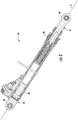
FIG. 2 is a cross section of the hydraulic piston actuator; -
FIG. 3 is a partial enlarged cross section of the hydraulic piston actuator; -
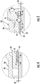
FIG. 4 is a cross section of the hydraulic piston actuator taken fromcircle 4 ofFIG. 3 ; and -
FIG. 5 is a cross section of the hydraulic piston actuator taken from circle 5 ofFIG. 3 . - Referring to
FIG. 1 , anaircraft engine nacelle 20 havingaccess cowl doors 22 is illustrated as one application of ahydraulic piston actuator 24. Thecowl door 22 may be hinged, or pivotally connected, to asubstructure 26 of theengine nacelle 20. For eachcowl door 22, at least onepiston actuator 24 may be pivotally connected between thesubstructure 26 and thecowl door 22 to facilitate opening and closing of the door. It is contemplated and understood that thedoor 22 may be other door types including, for example, hatches or doors, used on automobiles or any other application where thepiston actuator 24 may be exposed to vibrations. In one embodiment, thehydraulic piston actuator 24 may be a dry sliding piston actuator. In further embodiments, the dry slidingpiston actuator 24 may be applied to any application that may be exposed to radial loads caused, for example, by vibration. - Referring to
FIGS. 1 and2 , thehydraulic piston actuator 24 may include ahousing 30 and anelongated piston 32 adapted to reciprocate within thehousing 30 along an axis A. Thehousing 30 may includeopposite end portions 34, 36, and thepiston 32 may include opposite end portion 38, 40. The end portion 34 of thehousing 30 may be pivotally engaged to thesubstructure 26, and thepiston 32 may project out of theend portion 36. The end portion 38 of thepiston 32 may generally reside within thehousing 30, and the opposite end portion 40 may be pivotally engaged to thecowl door 22. Alternatively, it is contemplated that thehousing 30 may be pivotally engaged to thecowl door 22 and thepiston 32 may be pivotally engaged to thesubstructure 26. - Referring to
FIG. 3 , thehydraulic piston actuator 24 may further include anend gland 42, abearing ring 44, and ascraper seal 46. Theend gland 42 is substantially disposed radially between theend portion 36 of thehousing 30 and thebearing ring 44. Thebearing ring 44 is disposed radially between theend gland 42 and thepiston 32. Thescraper seal 46 is disposed radially between theend gland 42 and thepiston 32, but may be axially offset from, or disposed outside of, thehousing 30. Theend gland 42 is adapted to withstand radially loads (see arrows 48) exerted upon theend portion 36 of thehousing 30 during operation and/or vibration of thepiston actuator 24. In one embodiment theend gland 42 and thepiston 32 may be metallic, and thepiston 32 may be made of a material that is harder than the end gland. For example, thepiston 32 may, at least in-part, be made of stainless steel and theend gland 42 may be made of a bronze alloy. - The
end gland 42 is generally annular and may include a circumferentiallycontinuous base segment 50 and an annular protrudingsegment 52 that projects radially outward from thebase segment 50. When thepiston actuator 24 is assembled, the protrudingsegment 52 may be disposed outside of thehousing 30 and may axially abut (i.e., is indexed to) a distal and circumferentiallycontinuous edge 54 of theend portion 36 of thehousing 30. Thebase segment 50 of theend gland 42 is substantially disposed inside of theend portion 36 of the housing 30 (i.e., disposed radially inward from the end portion 36), and is generally attached to theend portion 36. - Referring to
FIGS. 3 through 5 , thebase segment 50 of theend gland 42 may define anannular channel 56 that communicates radially inward (i.e., is open in a radially inward direction), and an annular groove, or bore, 58 that may also communicate radially inward. Thebase segment 50 may carry two circumferentially continuous surfaces 60, 62 that may be cylindrical, face radially inward, and oppose a circumferentiallycontinuous face 64 that may be cylindrical and carried by thepiston 32. First and second annular clearances (seerespective arrows 66, 68 inFIGS. 4 and 5 ) are defined between theface 64 and the respective surface 60, 62. In one embodiment, the radial and circumferential distances of the first clearance 66 may be about the same as the distances of thesecond clearance 68. The first and second surfaces 60, 62 may be axially separated by theannular channel 56, and theannular channel 56 may be axially separated from theannular groove 58 by the second surface 62. - The
scraper seal 46 is substantially disposed in thegroove 58, is generally engaged to thebase segment 50 of theend gland 42, and may be axially aligned to the protrudingsegment 52. Thescraper seal 46 projects radially inward from theend gland 42 for sliding contact with theface 64 of thepiston 32. In operation, thescraper seal 46 facilitates the removal of debris and water from thepiston 32 to prevent ingress into thehousing 30. - When the
piston actuator 24 is fully assembled and in operation, theend gland 42 does not make contact with thereciprocating piston 32, but does provide structural support for and at theend portion 36 of thehousing 30. The bearingring 44 that projects radially inward from theend gland 42, however, does make sliding contact with thereciprocating piston 32. To minimize friction between thepiston 32 and bearingseal 44, the bearing seal may be made of a thermoplastic that may be reinforced with carbon fibers that may contain graphite. Another advantage of the bearing seal material is the reduction or elimination of facial scoring of thepiston 32 and/or the reduction or elimination of material deposits being placed upon theface 64 of thepiston 32 from the bearingseal 44. By reducing any piston scoring or foreign deposits upon the piston face, thescraper seal 46 functionality and life may be optimized. - Advantages and benefits may include a piston actuator that does not require a lubricant (e.g., liquid lubricant) between various seals supported by the
housing 30 and sealing against thereciprocating piston 32 to prevent degradation of the piston surface caused by, for example, vibrations that produce radial loading. - The term "about" is intended to include the degree of error associated with measurement of the particular quantity based upon the equipment available at the time of filing the application. For example, "about" can include a range of ± 8% or 5%, or 2% of a given value.
- The terminology used herein is for the purpose of describing particular embodiments only and is not intended to be limiting of the present disclosure. As used herein, the singular forms "a", "an" and "the" are intended to include the plural forms as well, unless the context clearly indicates otherwise. It will be further understood that the terms "comprises" and/or "comprising," when used in this specification, specify the presence of stated features, integers, steps, operations, elements, and/or components, but do not preclude the presence or addition of one or more other features, integers, steps, operations, element components, and/or groups thereof.
- While the present disclosure has been described with reference to an exemplary embodiment or embodiments, it will be understood by those skilled in the art that various changes may be made and equivalents may be substituted for elements thereof without departing from the scope of the present disclosure. In addition, many modifications may be made to adapt a particular situation or material to the teachings of the present disclosure without departing from the essential scope thereof. Therefore, it is intended that the present disclosure not be limited to the particular embodiment disclosed as the best mode contemplated for carrying out this present disclosure, but that the present disclosure will include all embodiments falling within the scope of the claims.
Claims (15)
- A hydraulic piston actuator (24) comprising:a housing (30) concentrically disposed along an axis (A);a piston (32) adapted to axially reciprocate within the housing (30);an end gland (42) disposed radially between the housing (30) and the piston (32); anda bearing ring (44) disposed radially between the end gland (42) and the piston (32).
- The hydraulic piston actuator (24) set forth in claim 1, wherein the end gland (42) is fixed to the housing (30).
- The hydraulic piston actuator (24) set forth in claim 2, further comprising:a scraper seal (46) disposed radially between the end gland (42) and the piston (32).
- The hydraulic piston actuator (24) set forth in claim 3, wherein the scraper seal (46) is axially spaced outward from the bearing ring (44).
- The hydraulic piston actuator (24) set forth in any preceding claim, wherein the end gland (42) defines an annular channel (56) communicating radially inward, and the bearing ring (44) is substantially disposed in the channel (56).
- The hydraulic piston actuator (24) set forth in claim 4, wherein the end gland (42) defines a circumferentially continuous channel communicating radially inward, and the bearing ring (44) is substantially disposed in the channel.
- The hydraulic piston actuator (24) set forth in claim 6, wherein the piston (32) includes a cylindrical face facing radially outward, and the end gland (42) includes a first and second cylindrical surfaces spaced axially apart by the channel and opposing the cylindrical face.
- The hydraulic piston actuator set forth in claim 7, wherein the scraper seal (46) is axially spaced from the bearing ring (44) by the second cylindrical surface.
- The hydraulic piston actuator (24) set forth in claim 8, wherein a first clearance is defined by and between the first cylindrical surface and the cylindrical face, and a second clearance is defined by and between the second cylindrical surface and the cylindrical face.
- The hydraulic piston actuator (24) set forth in claim 9, wherein the bearing ring (44) is in sliding contact with the cylindrical face.
- The hydraulic piston actuator (24) set forth in claim 10, wherein the scraper seal (46) is in sliding contact with the cylindrical face.
- The hydraulic piston actuator (24) set forth in any preceding claim, wherein the bearing ring (44) is made of a material that includes thermoplastic, and the piston is metallic.
- The hydraulic piston actuator (24) set forth in claim 12, wherein the thermoplastic is re-inforced with carbon fiber/graphite.
- The hydraulic piston actuator (24) set forth in claim 13, wherein the piston (32) is made of stainless steel.
- An aircraft nacelle assembly (20) comprising:a substructure;a cowl door (22) pivotally connected to the substructure; anda hydraulic piston actuator (24) including:a housing (30) concentrically disposed along an axis (A) and pivotally connected to one of the substructure and the cowl door (22);a piston (32) adapted to axially reciprocate within the housing (30) and pivotally connected to the other of the substructure and the cowl door (22);an end gland (42) fixed to the housing (30) and disposed radially between the housing (30) and the piston (32);a bearing ring (44) fixed to the end gland (42) and projecting radially inward from the end gland (42) for sliding contact with the piston (32); anda scraper seal (46) supported by the housing (30) and in sliding contact with the piston (32).
Applications Claiming Priority (1)
| Application Number | Priority Date | Filing Date | Title |
|---|---|---|---|
| IN201711040414 | 2017-11-13 |
Publications (2)
| Publication Number | Publication Date |
|---|---|
| EP3483455A1 true EP3483455A1 (en) | 2019-05-15 |
| EP3483455B1 EP3483455B1 (en) | 2023-09-27 |
Family
ID=64184013
Family Applications (1)
| Application Number | Title | Priority Date | Filing Date |
|---|---|---|---|
| EP18205020.3A Active EP3483455B1 (en) | 2017-11-13 | 2018-11-07 | Aircraft nacelle assembly |
Country Status (3)
| Country | Link |
|---|---|
| US (1) | US11078708B2 (en) |
| EP (1) | EP3483455B1 (en) |
| CA (1) | CA3024245A1 (en) |
Cited By (2)
| Publication number | Priority date | Publication date | Assignee | Title |
|---|---|---|---|---|
| EP3613999A1 (en) * | 2018-08-21 | 2020-02-26 | Parker Hannifin Corp. | Externally verifiable thermal compensation of cowl opening actuator |
| IT202000014272A1 (en) * | 2020-06-16 | 2021-12-16 | Gabriele Guizzardi | METHOD OF PRODUCTION OF A ROD FOR A HYDRAULIC OR PNEUMATIC CYLINDER ROD, METHOD OF PRODUCTION OF A RELATED ROD, ROD PRODUCED WITH SAYING METHOD AND HYDRAULIC OR PNEUMATIC CYLINDER INCLUDING SAID ROD |
Families Citing this family (2)
| Publication number | Priority date | Publication date | Assignee | Title |
|---|---|---|---|---|
| US11085465B2 (en) * | 2019-03-11 | 2021-08-10 | Goodrich Corporation | Retention systems for light weight actuator glands |
| WO2025162565A1 (en) * | 2024-01-31 | 2025-08-07 | Safran Landing Systems | Linear actuator with damper |
Citations (4)
| Publication number | Priority date | Publication date | Assignee | Title |
|---|---|---|---|---|
| GB2095333A (en) * | 1981-03-19 | 1982-09-29 | Pneumo Corp | Hydraulic cowl door actuator with antivibration loading device and assembly employing same |
| FR2615914A1 (en) * | 1987-06-01 | 1988-12-02 | Moselle Ateliers Chantiers | Hydraulic or pneumatic jack equipped with a rapidly dismantlable sealing bearing |
| US20010047719A1 (en) * | 2000-01-17 | 2001-12-06 | Susumu Niwa | Hydraulic cylinder |
| WO2015143217A1 (en) * | 2014-03-19 | 2015-09-24 | Marathonnorco Aerospace, Inc. | Pull then lift hold open rod lock mechanism |
Family Cites Families (6)
| Publication number | Priority date | Publication date | Assignee | Title |
|---|---|---|---|---|
| US4399966A (en) * | 1980-12-31 | 1983-08-23 | The Boeing Company | Power opening system for engine cowl doors |
| US4582329A (en) | 1984-11-08 | 1986-04-15 | Combustion Engineering, Inc. | Sealing bearing arrangement with convex bushing ring |
| IN166825B (en) * | 1985-04-30 | 1990-07-21 | Dowty Boulton Paul Ltd | |
| US8814432B2 (en) | 2012-03-23 | 2014-08-26 | Seal-Ryt Corporation | Seal-bearing assembly |
| US20160025220A1 (en) * | 2014-07-22 | 2016-01-28 | Spx Corporation | Actuation Rod Lubrication System And Method |
| EP3059369B1 (en) * | 2015-02-19 | 2021-09-01 | Goodrich Actuation Systems Ltd. | Actuator mechanism |
-
2018
- 2018-02-15 US US15/897,600 patent/US11078708B2/en active Active
- 2018-11-07 EP EP18205020.3A patent/EP3483455B1/en active Active
- 2018-11-09 CA CA3024245A patent/CA3024245A1/en active Pending
Patent Citations (4)
| Publication number | Priority date | Publication date | Assignee | Title |
|---|---|---|---|---|
| GB2095333A (en) * | 1981-03-19 | 1982-09-29 | Pneumo Corp | Hydraulic cowl door actuator with antivibration loading device and assembly employing same |
| FR2615914A1 (en) * | 1987-06-01 | 1988-12-02 | Moselle Ateliers Chantiers | Hydraulic or pneumatic jack equipped with a rapidly dismantlable sealing bearing |
| US20010047719A1 (en) * | 2000-01-17 | 2001-12-06 | Susumu Niwa | Hydraulic cylinder |
| WO2015143217A1 (en) * | 2014-03-19 | 2015-09-24 | Marathonnorco Aerospace, Inc. | Pull then lift hold open rod lock mechanism |
Cited By (3)
| Publication number | Priority date | Publication date | Assignee | Title |
|---|---|---|---|---|
| EP3613999A1 (en) * | 2018-08-21 | 2020-02-26 | Parker Hannifin Corp. | Externally verifiable thermal compensation of cowl opening actuator |
| US11293463B2 (en) | 2018-08-21 | 2022-04-05 | Parker-Hannifin Corporation | Externally verifiable thermal compensation of cowl opening actuator |
| IT202000014272A1 (en) * | 2020-06-16 | 2021-12-16 | Gabriele Guizzardi | METHOD OF PRODUCTION OF A ROD FOR A HYDRAULIC OR PNEUMATIC CYLINDER ROD, METHOD OF PRODUCTION OF A RELATED ROD, ROD PRODUCED WITH SAYING METHOD AND HYDRAULIC OR PNEUMATIC CYLINDER INCLUDING SAID ROD |
Also Published As
| Publication number | Publication date |
|---|---|
| US11078708B2 (en) | 2021-08-03 |
| US20190145144A1 (en) | 2019-05-16 |
| BR102018073256A2 (en) | 2019-10-22 |
| EP3483455B1 (en) | 2023-09-27 |
| CA3024245A1 (en) | 2019-05-13 |
Similar Documents
| Publication | Publication Date | Title |
|---|---|---|
| EP3483455B1 (en) | Aircraft nacelle assembly | |
| US6139261A (en) | Bushing assembly with removable wear sleeve | |
| US5244215A (en) | Rotary shaft seal with retractable excluder lip | |
| US6315296B1 (en) | Flangeless retrofittable severe duty seal for a shaft | |
| EP3208503B1 (en) | Ceramic seal runner support system | |
| EP2594790A1 (en) | Sealing assembly | |
| JP2016118195A (en) | Modular turbocharger clearance seal | |
| US20150001810A1 (en) | Dynamically Non Contacting Seal | |
| US9347333B2 (en) | Brush ring seal | |
| RU2599692C1 (en) | Cassette seal | |
| EP3486501B1 (en) | Actuator assembly having self-lubricating components | |
| CN108019518A (en) | Reciprocating air cylinder sleeve seal assembly | |
| DE102020101315A1 (en) | Orbiter vacuum pump with optimized storage | |
| CN1280562C (en) | ball valve | |
| US10823248B2 (en) | Hydraulic damper | |
| EP2742243B1 (en) | Pump shaft seal using sealing rings and a bellows for retention of bearing lubricant | |
| EP4379209B1 (en) | AXIAL SEAL FOR A GENERATOR ROTOR OF A WIND TURBINE | |
| EP3486534B1 (en) | Rotational mechanical systems having reduced friction sealing surfaces | |
| JP2021076141A (en) | Seal device | |
| DE102008059002A1 (en) | Loading device, particularly exhaust turbo charger for internal-combustion engine of motor vehicle, comprises rotor and stator, in which rotor is stored swiveling around rotation axle | |
| BR102018073256B1 (en) | AIRCRAFT NACELLE ASSEMBLY | |
| RU2611706C1 (en) | Radial-end gas dynamic seal of turbo machines rotors supports oil cavity | |
| WO2020002292A1 (en) | Sealing arrangement for an electric machine, manufacturing method of sealing and sealing method | |
| US20160138654A1 (en) | Floating wind turbine bearing seal with enhanced profile | |
| WO2011159867A1 (en) | Floating wind turbine bearing seal with symmetrical profile |
Legal Events
| Date | Code | Title | Description |
|---|---|---|---|
| PUAI | Public reference made under article 153(3) epc to a published international application that has entered the european phase |
Free format text: ORIGINAL CODE: 0009012 |
|
| STAA | Information on the status of an ep patent application or granted ep patent |
Free format text: STATUS: THE APPLICATION HAS BEEN PUBLISHED |
|
| AK | Designated contracting states |
Kind code of ref document: A1 Designated state(s): AL AT BE BG CH CY CZ DE DK EE ES FI FR GB GR HR HU IE IS IT LI LT LU LV MC MK MT NL NO PL PT RO RS SE SI SK SM TR |
|
| AX | Request for extension of the european patent |
Extension state: BA ME |
|
| STAA | Information on the status of an ep patent application or granted ep patent |
Free format text: STATUS: REQUEST FOR EXAMINATION WAS MADE |
|
| 17P | Request for examination filed |
Effective date: 20191115 |
|
| RBV | Designated contracting states (corrected) |
Designated state(s): AL AT BE BG CH CY CZ DE DK EE ES FI FR GB GR HR HU IE IS IT LI LT LU LV MC MK MT NL NO PL PT RO RS SE SI SK SM TR |
|
| STAA | Information on the status of an ep patent application or granted ep patent |
Free format text: STATUS: EXAMINATION IS IN PROGRESS |
|
| 17Q | First examination report despatched |
Effective date: 20200417 |
|
| GRAP | Despatch of communication of intention to grant a patent |
Free format text: ORIGINAL CODE: EPIDOSNIGR1 |
|
| STAA | Information on the status of an ep patent application or granted ep patent |
Free format text: STATUS: GRANT OF PATENT IS INTENDED |
|
| INTG | Intention to grant announced |
Effective date: 20230419 |
|
| GRAS | Grant fee paid |
Free format text: ORIGINAL CODE: EPIDOSNIGR3 |
|
| GRAA | (expected) grant |
Free format text: ORIGINAL CODE: 0009210 |
|
| STAA | Information on the status of an ep patent application or granted ep patent |
Free format text: STATUS: THE PATENT HAS BEEN GRANTED |
|
| AK | Designated contracting states |
Kind code of ref document: B1 Designated state(s): AL AT BE BG CH CY CZ DE DK EE ES FI FR GB GR HR HU IE IS IT LI LT LU LV MC MK MT NL NO PL PT RO RS SE SI SK SM TR |
|
| REG | Reference to a national code |
Ref country code: GB Ref legal event code: FG4D |
|
| REG | Reference to a national code |
Ref country code: CH Ref legal event code: EP |
|
| REG | Reference to a national code |
Ref country code: DE Ref legal event code: R096 Ref document number: 602018058187 Country of ref document: DE |
|
| REG | Reference to a national code |
Ref country code: IE Ref legal event code: FG4D |
|
| REG | Reference to a national code |
Ref country code: LT Ref legal event code: MG9D |
|
| PG25 | Lapsed in a contracting state [announced via postgrant information from national office to epo] |
Ref country code: GR Free format text: LAPSE BECAUSE OF FAILURE TO SUBMIT A TRANSLATION OF THE DESCRIPTION OR TO PAY THE FEE WITHIN THE PRESCRIBED TIME-LIMIT Effective date: 20231228 |
|
| PG25 | Lapsed in a contracting state [announced via postgrant information from national office to epo] |
Ref country code: SE Free format text: LAPSE BECAUSE OF FAILURE TO SUBMIT A TRANSLATION OF THE DESCRIPTION OR TO PAY THE FEE WITHIN THE PRESCRIBED TIME-LIMIT Effective date: 20230927 Ref country code: RS Free format text: LAPSE BECAUSE OF FAILURE TO SUBMIT A TRANSLATION OF THE DESCRIPTION OR TO PAY THE FEE WITHIN THE PRESCRIBED TIME-LIMIT Effective date: 20230927 Ref country code: NO Free format text: LAPSE BECAUSE OF FAILURE TO SUBMIT A TRANSLATION OF THE DESCRIPTION OR TO PAY THE FEE WITHIN THE PRESCRIBED TIME-LIMIT Effective date: 20231227 Ref country code: LV Free format text: LAPSE BECAUSE OF FAILURE TO SUBMIT A TRANSLATION OF THE DESCRIPTION OR TO PAY THE FEE WITHIN THE PRESCRIBED TIME-LIMIT Effective date: 20230927 Ref country code: LT Free format text: LAPSE BECAUSE OF FAILURE TO SUBMIT A TRANSLATION OF THE DESCRIPTION OR TO PAY THE FEE WITHIN THE PRESCRIBED TIME-LIMIT Effective date: 20230927 Ref country code: HR Free format text: LAPSE BECAUSE OF FAILURE TO SUBMIT A TRANSLATION OF THE DESCRIPTION OR TO PAY THE FEE WITHIN THE PRESCRIBED TIME-LIMIT Effective date: 20230927 Ref country code: GR Free format text: LAPSE BECAUSE OF FAILURE TO SUBMIT A TRANSLATION OF THE DESCRIPTION OR TO PAY THE FEE WITHIN THE PRESCRIBED TIME-LIMIT Effective date: 20231228 Ref country code: FI Free format text: LAPSE BECAUSE OF FAILURE TO SUBMIT A TRANSLATION OF THE DESCRIPTION OR TO PAY THE FEE WITHIN THE PRESCRIBED TIME-LIMIT Effective date: 20230927 |
|
| REG | Reference to a national code |
Ref country code: NL Ref legal event code: MP Effective date: 20230927 |
|
| REG | Reference to a national code |
Ref country code: AT Ref legal event code: MK05 Ref document number: 1615676 Country of ref document: AT Kind code of ref document: T Effective date: 20230927 |
|
| PG25 | Lapsed in a contracting state [announced via postgrant information from national office to epo] |
Ref country code: NL Free format text: LAPSE BECAUSE OF FAILURE TO SUBMIT A TRANSLATION OF THE DESCRIPTION OR TO PAY THE FEE WITHIN THE PRESCRIBED TIME-LIMIT Effective date: 20230927 |
|
| PG25 | Lapsed in a contracting state [announced via postgrant information from national office to epo] |
Ref country code: IS Free format text: LAPSE BECAUSE OF FAILURE TO SUBMIT A TRANSLATION OF THE DESCRIPTION OR TO PAY THE FEE WITHIN THE PRESCRIBED TIME-LIMIT Effective date: 20240127 |
|
| PG25 | Lapsed in a contracting state [announced via postgrant information from national office to epo] |
Ref country code: AT Free format text: LAPSE BECAUSE OF FAILURE TO SUBMIT A TRANSLATION OF THE DESCRIPTION OR TO PAY THE FEE WITHIN THE PRESCRIBED TIME-LIMIT Effective date: 20230927 |
|
| PG25 | Lapsed in a contracting state [announced via postgrant information from national office to epo] |
Ref country code: ES Free format text: LAPSE BECAUSE OF FAILURE TO SUBMIT A TRANSLATION OF THE DESCRIPTION OR TO PAY THE FEE WITHIN THE PRESCRIBED TIME-LIMIT Effective date: 20230927 |
|
| PG25 | Lapsed in a contracting state [announced via postgrant information from national office to epo] |
Ref country code: SM Free format text: LAPSE BECAUSE OF FAILURE TO SUBMIT A TRANSLATION OF THE DESCRIPTION OR TO PAY THE FEE WITHIN THE PRESCRIBED TIME-LIMIT Effective date: 20230927 Ref country code: RO Free format text: LAPSE BECAUSE OF FAILURE TO SUBMIT A TRANSLATION OF THE DESCRIPTION OR TO PAY THE FEE WITHIN THE PRESCRIBED TIME-LIMIT Effective date: 20230927 Ref country code: IS Free format text: LAPSE BECAUSE OF FAILURE TO SUBMIT A TRANSLATION OF THE DESCRIPTION OR TO PAY THE FEE WITHIN THE PRESCRIBED TIME-LIMIT Effective date: 20240127 Ref country code: ES Free format text: LAPSE BECAUSE OF FAILURE TO SUBMIT A TRANSLATION OF THE DESCRIPTION OR TO PAY THE FEE WITHIN THE PRESCRIBED TIME-LIMIT Effective date: 20230927 Ref country code: EE Free format text: LAPSE BECAUSE OF FAILURE TO SUBMIT A TRANSLATION OF THE DESCRIPTION OR TO PAY THE FEE WITHIN THE PRESCRIBED TIME-LIMIT Effective date: 20230927 Ref country code: CZ Free format text: LAPSE BECAUSE OF FAILURE TO SUBMIT A TRANSLATION OF THE DESCRIPTION OR TO PAY THE FEE WITHIN THE PRESCRIBED TIME-LIMIT Effective date: 20230927 Ref country code: AT Free format text: LAPSE BECAUSE OF FAILURE TO SUBMIT A TRANSLATION OF THE DESCRIPTION OR TO PAY THE FEE WITHIN THE PRESCRIBED TIME-LIMIT Effective date: 20230927 Ref country code: PT Free format text: LAPSE BECAUSE OF FAILURE TO SUBMIT A TRANSLATION OF THE DESCRIPTION OR TO PAY THE FEE WITHIN THE PRESCRIBED TIME-LIMIT Effective date: 20240129 Ref country code: SK Free format text: LAPSE BECAUSE OF FAILURE TO SUBMIT A TRANSLATION OF THE DESCRIPTION OR TO PAY THE FEE WITHIN THE PRESCRIBED TIME-LIMIT Effective date: 20230927 |
|
| PG25 | Lapsed in a contracting state [announced via postgrant information from national office to epo] |
Ref country code: PL Free format text: LAPSE BECAUSE OF FAILURE TO SUBMIT A TRANSLATION OF THE DESCRIPTION OR TO PAY THE FEE WITHIN THE PRESCRIBED TIME-LIMIT Effective date: 20230927 |
|
| REG | Reference to a national code |
Ref country code: DE Ref legal event code: R097 Ref document number: 602018058187 Country of ref document: DE Ref country code: CH Ref legal event code: PL |
|
| PG25 | Lapsed in a contracting state [announced via postgrant information from national office to epo] |
Ref country code: MC Free format text: LAPSE BECAUSE OF FAILURE TO SUBMIT A TRANSLATION OF THE DESCRIPTION OR TO PAY THE FEE WITHIN THE PRESCRIBED TIME-LIMIT Effective date: 20230927 |
|
| PG25 | Lapsed in a contracting state [announced via postgrant information from national office to epo] |
Ref country code: DK Free format text: LAPSE BECAUSE OF FAILURE TO SUBMIT A TRANSLATION OF THE DESCRIPTION OR TO PAY THE FEE WITHIN THE PRESCRIBED TIME-LIMIT Effective date: 20230927 |
|
| PG25 | Lapsed in a contracting state [announced via postgrant information from national office to epo] |
Ref country code: LU Free format text: LAPSE BECAUSE OF NON-PAYMENT OF DUE FEES Effective date: 20231107 |
|
| PG25 | Lapsed in a contracting state [announced via postgrant information from national office to epo] |
Ref country code: CH Free format text: LAPSE BECAUSE OF NON-PAYMENT OF DUE FEES Effective date: 20231130 |
|
| PG25 | Lapsed in a contracting state [announced via postgrant information from national office to epo] |
Ref country code: MC Free format text: LAPSE BECAUSE OF FAILURE TO SUBMIT A TRANSLATION OF THE DESCRIPTION OR TO PAY THE FEE WITHIN THE PRESCRIBED TIME-LIMIT Effective date: 20230927 Ref country code: LU Free format text: LAPSE BECAUSE OF NON-PAYMENT OF DUE FEES Effective date: 20231107 Ref country code: DK Free format text: LAPSE BECAUSE OF FAILURE TO SUBMIT A TRANSLATION OF THE DESCRIPTION OR TO PAY THE FEE WITHIN THE PRESCRIBED TIME-LIMIT Effective date: 20230927 Ref country code: CH Free format text: LAPSE BECAUSE OF NON-PAYMENT OF DUE FEES Effective date: 20231130 |
|
| REG | Reference to a national code |
Ref country code: BE Ref legal event code: MM Effective date: 20231130 |
|
| PLBE | No opposition filed within time limit |
Free format text: ORIGINAL CODE: 0009261 |
|
| STAA | Information on the status of an ep patent application or granted ep patent |
Free format text: STATUS: NO OPPOSITION FILED WITHIN TIME LIMIT |
|
| 26N | No opposition filed |
Effective date: 20240628 |
|
| REG | Reference to a national code |
Ref country code: IE Ref legal event code: MM4A |
|
| PG25 | Lapsed in a contracting state [announced via postgrant information from national office to epo] |
Ref country code: IE Free format text: LAPSE BECAUSE OF NON-PAYMENT OF DUE FEES Effective date: 20231107 |
|
| PG25 | Lapsed in a contracting state [announced via postgrant information from national office to epo] |
Ref country code: BE Free format text: LAPSE BECAUSE OF NON-PAYMENT OF DUE FEES Effective date: 20231130 |
|
| PG25 | Lapsed in a contracting state [announced via postgrant information from national office to epo] |
Ref country code: SI Free format text: LAPSE BECAUSE OF FAILURE TO SUBMIT A TRANSLATION OF THE DESCRIPTION OR TO PAY THE FEE WITHIN THE PRESCRIBED TIME-LIMIT Effective date: 20230927 |
|
| PG25 | Lapsed in a contracting state [announced via postgrant information from national office to epo] |
Ref country code: SI Free format text: LAPSE BECAUSE OF FAILURE TO SUBMIT A TRANSLATION OF THE DESCRIPTION OR TO PAY THE FEE WITHIN THE PRESCRIBED TIME-LIMIT Effective date: 20230927 Ref country code: IE Free format text: LAPSE BECAUSE OF NON-PAYMENT OF DUE FEES Effective date: 20231107 Ref country code: BE Free format text: LAPSE BECAUSE OF NON-PAYMENT OF DUE FEES Effective date: 20231130 |
|
| PG25 | Lapsed in a contracting state [announced via postgrant information from national office to epo] |
Ref country code: BG Free format text: LAPSE BECAUSE OF FAILURE TO SUBMIT A TRANSLATION OF THE DESCRIPTION OR TO PAY THE FEE WITHIN THE PRESCRIBED TIME-LIMIT Effective date: 20230927 |
|
| PG25 | Lapsed in a contracting state [announced via postgrant information from national office to epo] |
Ref country code: BG Free format text: LAPSE BECAUSE OF FAILURE TO SUBMIT A TRANSLATION OF THE DESCRIPTION OR TO PAY THE FEE WITHIN THE PRESCRIBED TIME-LIMIT Effective date: 20230927 |
|
| PG25 | Lapsed in a contracting state [announced via postgrant information from national office to epo] |
Ref country code: CY Free format text: LAPSE BECAUSE OF FAILURE TO SUBMIT A TRANSLATION OF THE DESCRIPTION OR TO PAY THE FEE WITHIN THE PRESCRIBED TIME-LIMIT; INVALID AB INITIO Effective date: 20181107 |
|
| PG25 | Lapsed in a contracting state [announced via postgrant information from national office to epo] |
Ref country code: HU Free format text: LAPSE BECAUSE OF FAILURE TO SUBMIT A TRANSLATION OF THE DESCRIPTION OR TO PAY THE FEE WITHIN THE PRESCRIBED TIME-LIMIT; INVALID AB INITIO Effective date: 20181107 |
|
| PG25 | Lapsed in a contracting state [announced via postgrant information from national office to epo] |
Ref country code: TR Free format text: LAPSE BECAUSE OF FAILURE TO SUBMIT A TRANSLATION OF THE DESCRIPTION OR TO PAY THE FEE WITHIN THE PRESCRIBED TIME-LIMIT Effective date: 20230927 |
|
| PGFP | Annual fee paid to national office [announced via postgrant information from national office to epo] |
Ref country code: DE Payment date: 20251117 Year of fee payment: 8 |
|
| PGFP | Annual fee paid to national office [announced via postgrant information from national office to epo] |
Ref country code: GB Payment date: 20251126 Year of fee payment: 8 |
|
| PGFP | Annual fee paid to national office [announced via postgrant information from national office to epo] |
Ref country code: IT Payment date: 20251107 Year of fee payment: 8 |
|
| PGFP | Annual fee paid to national office [announced via postgrant information from national office to epo] |
Ref country code: FR Payment date: 20251128 Year of fee payment: 8 |