EP3483439A1 - Abrasion and puncture resistant diaphragm - Google Patents
Abrasion and puncture resistant diaphragm Download PDFInfo
- Publication number
- EP3483439A1 EP3483439A1 EP18204744.9A EP18204744A EP3483439A1 EP 3483439 A1 EP3483439 A1 EP 3483439A1 EP 18204744 A EP18204744 A EP 18204744A EP 3483439 A1 EP3483439 A1 EP 3483439A1
- Authority
- EP
- European Patent Office
- Prior art keywords
- diaphragm
- fabric
- fluid chamber
- pump
- fluid
- Prior art date
- Legal status (The legal status is an assumption and is not a legal conclusion. Google has not performed a legal analysis and makes no representation as to the accuracy of the status listed.)
- Granted
Links
Images

Classifications
-
- F—MECHANICAL ENGINEERING; LIGHTING; HEATING; WEAPONS; BLASTING
- F04—POSITIVE - DISPLACEMENT MACHINES FOR LIQUIDS; PUMPS FOR LIQUIDS OR ELASTIC FLUIDS
- F04B—POSITIVE-DISPLACEMENT MACHINES FOR LIQUIDS; PUMPS
- F04B43/00—Machines, pumps, or pumping installations having flexible working members
- F04B43/0009—Special features
- F04B43/0054—Special features particularities of the flexible members
-
- F—MECHANICAL ENGINEERING; LIGHTING; HEATING; WEAPONS; BLASTING
- F04—POSITIVE - DISPLACEMENT MACHINES FOR LIQUIDS; PUMPS FOR LIQUIDS OR ELASTIC FLUIDS
- F04B—POSITIVE-DISPLACEMENT MACHINES FOR LIQUIDS; PUMPS
- F04B43/00—Machines, pumps, or pumping installations having flexible working members
- F04B43/02—Machines, pumps, or pumping installations having flexible working members having plate-like flexible members, e.g. diaphragms
- F04B43/06—Pumps having fluid drive
Definitions
- the present disclosure relates to pumps such as diaphragm pumps.
- the present disclosure relates to a diaphragm used in such diaphragm pumps, wherein the diaphragm is a composite of a flexible elastomer diaphragm body with a woven high strength fabric layer applied on top to resist possible abrasion or puncture to the diaphragm body.
- Pumps that move fluid from one location to another location such as diaphragm pumps, for example, are known.
- These pumps typically include one or more flexible diaphragms.
- a diaphragm is linearly moved in one direction to draw in fluid from a fluid source.
- the diaphragm then moves in the opposite direction to push that fluid out to another location.
- By repeatedly moving the diaphragm back and forth fluid is consistently drawn into and pushed out of the pump.
- the fluid is moved through a fluid chamber that houses the diaphragm between inlet and outlet manifolds.
- Typical diaphragms used in such pumps like an air operated double diaphragm (AODD) pump are made from thermoplastic or synthetic elastomers. They are sufficiently flexible and durable to help draw in and push out fluid to and from the pump. That said, because of the different types of fluid that are pumped through the pump, the diaphragm may be susceptible to wear or damage. In some environments, for example, the diaphragms may move chemicals that might attack the elastomer material. Polytetrafluoroethylene (PTFE) can, therefore, be added to the diaphragm to serve as a protective component. In some instances, however, the fluid may contain physical objects that could impact the diaphragm.
- PTFE polytetrafluoroethylene
- TPU thermoplastic polyurethane
- the diaphragm pump comprises an inlet; a fluid chamber in fluid communication with the inlet; an outlet in fluid communication with the fluid chamber; wherein the fluid chamber includes a first portion and a second portion; wherein fluid from a fluid source moves through the first portion of the fluid chamber; a diaphragm located in the fluid chamber; wherein the diaphragm separates the first portion of the fluid chamber from the second portion of the fluid chamber; wherein the diaphragm is a flexible disc-shaped structure made from an elastomer material; wherein the diaphragm has an outer edge configured to be held by the fluid chamber; wherein the diaphragm includes a first surface that faces the first portion of the fluid chamber and a second surface that faces the second portion of the fluid chamber; and a fabric applied on the first surface of the diaphragm facing the first portion of the fluid chamber so the fabric faces the fluid that is moved through the first portion of the fluid chamber; where
- the diaphragm pump may further comprise: wherein the fabric being applied to the first surface of the diaphragm by a means selected from the group consisting of chemical bonding, chemical adhesion, over molding the diaphragm, an adhesive, mechanical fastener, and the diaphragm back-molded onto the fabric via injection or compression molding; the diaphragm pump being a double diaphragm pump; the diaphragm being made of a polyamide; the fabric being applied on the diaphragm such that the elastomer of the diaphragm is located in openings formed between fibers of the fabric; and the diaphragm being made of a poly ether block amide or other materials that have bonding capability with aramid based materials; the diaphragm including an opening disposed through the diaphragm to couple to a motive source that reciprocally moves the diaphragm alternately towards the first portion and away from the second portion.
- the diaphragm pump comprises a fluid chamber; a diaphragm located in the fluid chamber; wherein the diaphragm is a flexible disc-shaped structure made from an elastomer material; wherein the diaphragm has an outer edge; wherein the diaphragm includes a first surface; and a fabric that is applied on the first surface of the diaphragm; wherein the fabric is composed of woven aramid based fibers.
- the diaphragm pump may further comprise: an inlet, the fluid chamber in fluid communication with the inlet, and an outlet in fluid communication with the fluid chamber; the fluid chamber including a first portion and a second portion, and wherein fluid from a fluid source moves through the first portion of the fluid chamber; the diaphragm separating the first portion of the fluid chamber from the second portion of the fluid chamber; the diaphragm having an outer edge configured to be held by the fluid chamber; the first surface of the diaphragm facing the first portion of the fluid chamber and the diaphragm includes a second surface facing the second portion of the fluid chamber; the diaphragm, including an opening disposed through the diaphragm and the fabric, is applied onto the diaphragm about the opening; the fabric being applied onto the first surface of the diaphragm facing the first portion so the fabric faces the fluid that is moved through the first portion of the fluid chamber; and the fabric serves as a barrier between the first portion of the fluid chamber and
- the diaphragm for use in a pump.
- the diaphragm comprises a flexible disc-shaped body having a first surface and an outer edge; wherein the flexible disc-shaped body is made of an elastomer material; and a fabric applied on the first surface of the flexible disc-shaped body; and wherein the fabric is composed of woven aramid based fibers.
- the diaphragm pump may further comprise: the fabric being applied to the first surface of the diaphragm by a means selected from the group consisting of chemical bonding, chemical adhesion, over molding the diaphragm, an adhesive, mechanical fastener, and the diaphragm back-molded onto the fabric via injection or compression molding; the diaphragm being made of a material selected from the group consisting of polyamide and a poly ether block amide or other materials that have bonding capability with aramid based materials; and the fabric being applied onto the diaphragm such that the elastomer of the diaphragm is located in openings formed between fibers of the fabric.
- an illustrative embodiment of the present disclosure provides a composite diaphragm structure for use in a diaphragm pump.
- the composite diaphragm is such that the fluid contact side has an abrasion and puncture resistant layer to guard against these failure modes.
- the composite diaphragm may include a first diaphragm body layer that is made from an elastomer such as a polyamide and a second layer made of a woven fabric of para-aramid, meta-aramid, poly paraphenylene terephthalamide, or any other aramid based fibers, commonly known as Kevlar.
- the fabric may be applied and conformed to the size and shape of the elastomer diaphragm body. This ensures the puncture and abrasion resistance characteristics do not interfere with the shape of the diaphragm to allow it to operate in the pump.
- the fibers of the fabric layer may be made from ultra high molecular weight polyethylene (UHMWPE) bonded to a diaphragm made from polyethylene-based elastomer.
- UHMWPE ultra high molecular weight polyethylene
- FIG. 1 A perspective view of an illustrative double diaphragm pump 2 is shown in Fig. 1 . It is appreciated that either a single diaphragm or double diaphragm pump may employ the composite diaphragm of the present disclosure. Also, air operated, electric operated, or other means to drive the diaphragm may be employed as well. The skilled artisan, upon reading the present disclosure, will appreciate that the double diaphragm pump shown herein is for illustrative purposes. To that end, the illustrative double diaphragm pump 2 shown includes an inlet manifold 4, first and second fluid chambers 6 and 8, a drive mechanism 10, and an outlet manifold 12. A diaphragm, such as diaphragm 14 shown in Fig. 2 , is fitted into each of fluid chambers 6 and 8 and moves fluid from inlet manifold 4 to outlet manifold 12 as known by those skilled in the art.
- a diaphragm such as diaphragm 14 shown in Fig. 2
- diaphragm 14 is composed of a base layer 16 that forms the structural body of the diaphragm as shown.
- base layer 16 may be made of a compatible thermoplastic elastomer such as a poly ether block amide, thermoplastic vulcinizate (TPV) i.e., Santoprene with polyamide or Zeotherm alkyl acrylate copolymer (ACM) rubber plus polyamide, polyamide elastomers i.e., polyamide 12-block poly(tetramethylene ether) glycol (PTMEG), and polyamide based silicones.
- Top fabric layer 18 is a flexible Kevlar fabric that is applied onto base layer 16. Being flexible, the Kevlar of top layer 18 will conform to the shape of base layer 16.
- the Kevlar fabric of top layer 18 will be on the fluid-contact side of the diaphragm. This means that top layer 18 will be exposed to the fluid being pumped in from a fluid source through inlet manifold 4 and pumped out to outlet manifold 12 ( see, also, Fig. 1 ). It is this fluid that may contain media or other solids that has the potential to cause damage to the diaphragm. The Kevlar fabric of top layer 18 protects against that damage. It is also appreciated that the Kevlar may have chemical resistance to a wide range of chemicals which might help it in other applications - even where media and solids do not pose a risk.
- neck 20 and rim 22 of diaphragm 14 are shown in this view.
- neck 20 provides the structural support to engage a washer, fastener, or both, etc., that secures to the moving piston rod, screw, etc., that generates the reciprocal movement of diaphragm 14.
- rim 22 is the structural portion of diaphragm 14 that is held in place by the pump housing and fluid chamber head to keep the diaphragm in position and maintain a seal between the fluid chamber and the air or other motive fluid chamber that typical diaphragms segregate. It is appreciated that neither neck 20 or rim 22 necessarily require the Kevlar fabric of top layer 18. It will be appreciated by the skilled artisan upon reading this disclosure; however, that if deemed necessary because of the nature of the pump and/or the fluids being moved therethrough, top layer 18 may be applied to these structures as well.
- top layer 18 is laminated onto base layer 16.
- the fabric of top layer 18 may be applied to base layer 16 by such means as chemical bonding, chemical adhesion, or over molding with top layer 18.
- top layer 18 may be applied via adhesive or even a mechanical fastener.
- the diaphragm body that makes up base layer 16 may be back-molded into the fabric of top layer 18 via injection or compression molding.
- the elastomer of the diaphragm may migrate between the woven fibers of top layer 18 to further reinforce attachment of top layer 18 onto base layer 16.
- top layer 18 applied over rim 22 of base layer 16.
- rim 22 is configured to assist securing diaphragm 14 to the fluid chamber.
- top layer 18 may or may not extend over rim 22 of base layer 16.
- top layer 18 extends over rim 22 of base layer 16. But depending on the attachment characteristics, it may be advantageous for the fabric of top layer 18 not to extend over rim 22 in other embodiments. As such, the fabric of top layer 18 may be backed-off to expose base layer 16 at rim 22.
- top layer 18 is a separate Kevlar fabric layer distinguishable from the diaphragm structure body of base layer 16.
- the Kevlar fabric of top layer 18 is designed to withstand puncture and abrasion forces that may be applied to the diaphragm of base layer 16 when drawing in or pushing out fluid.
- top layer 18 is flexible enough to move with base layer 16 as diaphragm 14 is being pushed back and forth by a motive means creating the pumping action.
- neck 20 that surrounds bore 26 that receives a fastener or other structure to further secure diaphragm 14 onto the pump motive mechanism.
- opening 28 disposed through the Kevlar fabric of top layer 18 and is present for the same purposes.
- FIG. 5 A detailed cross dissection view of a portion of double diaphragm pump 2 is shown in Fig 5 .
- this view depicts the fluid chamber 6 portion of double diaphragm pump 2.
- a pump head 30 couples to a base 32 that forms fluid chamber cavity 34.
- Diaphragm 14 segregates fluid chamber cavity 34 into a pumped fluid-side portion 36 and non-pumped fluid-side portion 38.
- the pumped fluid-side portion 36 is the side where fluid being received through inlet manifold 4 enters fluid chamber 6 due to the movement of diaphragm 14.
- this is the side that requires top layer 18 since it is here the diaphragm will be susceptible to solids and other media that might otherwise damage diaphragm 14.
- Non-pumped fluid-side 38 may be used to receive motive fluid such as air or hydraulic fluid which assists moving diaphragm 14 to draw in and push out the fluid.
- washers 40 and 42 which sandwich diaphragm 14.
- Fastener 44 secures washers 40 and 42 onto diaphragm 14.
- fastener 44 secures those structures to a rod 46 which is either tied to another spaced apart diaphragm mechanism located in another fluid chambers (such as fluid chamber 8 shown in double diaphragm pump 2 and Fig. 2 ), or a motor or other structure to move diaphragm 14.
Landscapes
- Engineering & Computer Science (AREA)
- Mechanical Engineering (AREA)
- General Engineering & Computer Science (AREA)
- Reciprocating Pumps (AREA)
Abstract
Description
- The present disclosure relates to pumps such as diaphragm pumps. Particularly, the present disclosure relates to a diaphragm used in such diaphragm pumps, wherein the diaphragm is a composite of a flexible elastomer diaphragm body with a woven high strength fabric layer applied on top to resist possible abrasion or puncture to the diaphragm body.
- Pumps that move fluid from one location to another location such as diaphragm pumps, for example, are known. These pumps typically include one or more flexible diaphragms. A diaphragm is linearly moved in one direction to draw in fluid from a fluid source. The diaphragm then moves in the opposite direction to push that fluid out to another location. By repeatedly moving the diaphragm back and forth, fluid is consistently drawn into and pushed out of the pump. Typically, the fluid is moved through a fluid chamber that houses the diaphragm between inlet and outlet manifolds.
- Typical diaphragms used in such pumps like an air operated double diaphragm (AODD) pump are made from thermoplastic or synthetic elastomers. They are sufficiently flexible and durable to help draw in and push out fluid to and from the pump. That said, because of the different types of fluid that are pumped through the pump, the diaphragm may be susceptible to wear or damage. In some environments, for example, the diaphragms may move chemicals that might attack the elastomer material. Polytetrafluoroethylene (PTFE) can, therefore, be added to the diaphragm to serve as a protective component. In some instances, however, the fluid may contain physical objects that could impact the diaphragm. Pumping fluid that contains various media and solids such as chicken bones or ceramics/inorganic particles creates diaphragm abrasion and puncture failures because of the diaphragm's soft flexible material. A thermoplastic polyurethane (TPU) may be used to provide some resistance to abrasion, but, even there, the material has limitations and is not impervious to punctures.
- An illustrative embodiment of the present disclosure provides a diaphragm pump. The diaphragm pump comprises an inlet; a fluid chamber in fluid communication with the inlet; an outlet in fluid communication with the fluid chamber; wherein the fluid chamber includes a first portion and a second portion; wherein fluid from a fluid source moves through the first portion of the fluid chamber; a diaphragm located in the fluid chamber; wherein the diaphragm separates the first portion of the fluid chamber from the second portion of the fluid chamber; wherein the diaphragm is a flexible disc-shaped structure made from an elastomer material; wherein the diaphragm has an outer edge configured to be held by the fluid chamber; wherein the diaphragm includes a first surface that faces the first portion of the fluid chamber and a second surface that faces the second portion of the fluid chamber; and a fabric applied on the first surface of the diaphragm facing the first portion of the fluid chamber so the fabric faces the fluid that is moved through the first portion of the fluid chamber; wherein the fabric serves as a barrier between the first portion of the fluid chamber and the diaphragm; and wherein the fabric is composed of woven aramid based fibers.
- In the above and other illustrative embodiments, the diaphragm pump may further comprise: wherein the fabric being applied to the first surface of the diaphragm by a means selected from the group consisting of chemical bonding, chemical adhesion, over molding the diaphragm, an adhesive, mechanical fastener, and the diaphragm back-molded onto the fabric via injection or compression molding; the diaphragm pump being a double diaphragm pump; the diaphragm being made of a polyamide; the fabric being applied on the diaphragm such that the elastomer of the diaphragm is located in openings formed between fibers of the fabric; and the diaphragm being made of a poly ether block amide or other materials that have bonding capability with aramid based materials; the diaphragm including an opening disposed through the diaphragm to couple to a motive source that reciprocally moves the diaphragm alternately towards the first portion and away from the second portion.
- Another illustrative embodiment of the present disclosure provides a diaphragm pump. The diaphragm pump comprises a fluid chamber; a diaphragm located in the fluid chamber; wherein the diaphragm is a flexible disc-shaped structure made from an elastomer material; wherein the diaphragm has an outer edge; wherein the diaphragm includes a first surface; and a fabric that is applied on the first surface of the diaphragm; wherein the fabric is composed of woven aramid based fibers.
- In the above and other illustrative embodiments, the diaphragm pump may further comprise: an inlet, the fluid chamber in fluid communication with the inlet, and an outlet in fluid communication with the fluid chamber; the fluid chamber including a first portion and a second portion, and wherein fluid from a fluid source moves through the first portion of the fluid chamber; the diaphragm separating the first portion of the fluid chamber from the second portion of the fluid chamber; the diaphragm having an outer edge configured to be held by the fluid chamber; the first surface of the diaphragm facing the first portion of the fluid chamber and the diaphragm includes a second surface facing the second portion of the fluid chamber; the diaphragm, including an opening disposed through the diaphragm and the fabric, is applied onto the diaphragm about the opening; the fabric being applied onto the first surface of the diaphragm facing the first portion so the fabric faces the fluid that is moved through the first portion of the fluid chamber; and the fabric serves as a barrier between the first portion of the fluid chamber and the diaphragm.
- Another illustrative embodiment of the present disclosure provides a diaphragm for use in a pump. The diaphragm comprises a flexible disc-shaped body having a first surface and an outer edge; wherein the flexible disc-shaped body is made of an elastomer material; and a fabric applied on the first surface of the flexible disc-shaped body; and wherein the fabric is composed of woven aramid based fibers.
- In the above and other illustrative embodiments, the diaphragm pump may further comprise: the fabric being applied to the first surface of the diaphragm by a means selected from the group consisting of chemical bonding, chemical adhesion, over molding the diaphragm, an adhesive, mechanical fastener, and the diaphragm back-molded onto the fabric via injection or compression molding; the diaphragm being made of a material selected from the group consisting of polyamide and a poly ether block amide or other materials that have bonding capability with aramid based materials; and the fabric being applied onto the diaphragm such that the elastomer of the diaphragm is located in openings formed between fibers of the fabric.
- Additional features and advantages of the diaphragm will become apparent to those skilled in the art upon consideration of the following detailed description of the illustrated embodiments exemplifying best modes of carrying out the diaphragm as presently perceived.
- The concepts described in the present disclosure are illustrated by way of example and not by way of limitation in the accompanying figures. For simplicity and clarity of illustration, elements illustrated in the figures are not necessarily drawn to scale. For example, the dimensions of some elements may be exaggerated relative to other elements for clarity. Further, where considered appropriate, reference labels may be repeated among the figures to indicate corresponding or analogous elements.
-
Fig. 1 is a prospective view of an illustrative double diaphragm pump; -
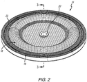
Fig. 2 is a prospective view of an illustrative embodiment of an abrasion and puncture resistant diagram for use in a pump such as that shown inFig. 1 ; -
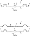
Fig. 3 is a side cross-sectional view of the diaphragm ofFig. 2 ; -
Fig. 4 is a side cross-sectional exploded view of the diaphragm ofFig. 2 ; -
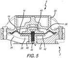
Fig. 5 is a side cross-sectional view of a fluid chamber portion of the diaphragm pump ofFig 1 showing the diaphragm ofFigs. 2 through 4 installed therein. - Corresponding reference characters indicate corresponding parts throughout the several views. The exemplification set out herein, illustrates embodiments of the diaphragm and such exemplification is not to be construed as limiting the scope of the diaphragm in any manner.
- The figures and descriptions provided herein may have been simplified to illustrate aspects that are relevant for a clear understanding of the herein described devices, systems, and methods, while eliminating, for the purpose of clarity, other aspects that may be found in typical devices, systems, and methods. Those of ordinary skill may recognize that other elements and/or operations may be desirable and/or necessary to implement the devices, systems, and methods described herein. Because such elements and operations are well known in the art, and because they do not facilitate a better understanding of the present disclosure, a discussion of such elements and operations may not be provided herein. However, the present disclosure is deemed to inherently include all such elements, variations, and modifications to the described aspects that would be known to those of ordinary skill in the art.
- Accordingly, an illustrative embodiment of the present disclosure provides a composite diaphragm structure for use in a diaphragm pump. The composite diaphragm is such that the fluid contact side has an abrasion and puncture resistant layer to guard against these failure modes. In a further embodiment of the present disclosure, the composite diaphragm may include a first diaphragm body layer that is made from an elastomer such as a polyamide and a second layer made of a woven fabric of para-aramid, meta-aramid, poly paraphenylene terephthalamide, or any other aramid based fibers, commonly known as Kevlar. The fabric may be applied and conformed to the size and shape of the elastomer diaphragm body. This ensures the puncture and abrasion resistance characteristics do not interfere with the shape of the diaphragm to allow it to operate in the pump. In another illustrative embodiment, the fibers of the fabric layer may be made from ultra high molecular weight polyethylene (UHMWPE) bonded to a diaphragm made from polyethylene-based elastomer.
- A perspective view of an illustrative
double diaphragm pump 2 is shown inFig. 1 . It is appreciated that either a single diaphragm or double diaphragm pump may employ the composite diaphragm of the present disclosure. Also, air operated, electric operated, or other means to drive the diaphragm may be employed as well. The skilled artisan, upon reading the present disclosure, will appreciate that the double diaphragm pump shown herein is for illustrative purposes. To that end, the illustrativedouble diaphragm pump 2 shown includes aninlet manifold 4, first andsecond fluid chambers drive mechanism 10, and anoutlet manifold 12. A diaphragm, such asdiaphragm 14 shown inFig. 2 , is fitted into each offluid chambers inlet manifold 4 tooutlet manifold 12 as known by those skilled in the art. - A perspective view of an illustrative embodiment of an abrasion and puncture
resistant diaphragm 14 is shown inFig. 2 . It is appreciated that the shape and configuration ofdiaphragm 14 is illustrative. Other shapes and contours employed for pump diaphragms may be employed and are contemplated to be part of this disclosure. With respect to the illustrated embodiment,diaphragm 14 is composed of abase layer 16 that forms the structural body of the diaphragm as shown. It is appreciated thatbase layer 16 may be made of a compatible thermoplastic elastomer such as a poly ether block amide, thermoplastic vulcinizate (TPV) i.e., Santoprene with polyamide or Zeotherm alkyl acrylate copolymer (ACM) rubber plus polyamide, polyamide elastomers i.e., polyamide 12-block poly(tetramethylene ether) glycol (PTMEG), and polyamide based silicones.Top fabric layer 18 is a flexible Kevlar fabric that is applied ontobase layer 16. Being flexible, the Kevlar oftop layer 18 will conform to the shape ofbase layer 16. It is appreciated, that the Kevlar fabric oftop layer 18 will be on the fluid-contact side of the diaphragm. This means thattop layer 18 will be exposed to the fluid being pumped in from a fluid source throughinlet manifold 4 and pumped out to outlet manifold 12 (see, also,Fig. 1 ). It is this fluid that may contain media or other solids that has the potential to cause damage to the diaphragm. The Kevlar fabric oftop layer 18 protects against that damage. It is also appreciated that the Kevlar may have chemical resistance to a wide range of chemicals which might help it in other applications - even where media and solids do not pose a risk. - Also shown in this view is
neck 20 and rim 22 ofdiaphragm 14. In the illustrated embodiment,neck 20 provides the structural support to engage a washer, fastener, or both, etc., that secures to the moving piston rod, screw, etc., that generates the reciprocal movement ofdiaphragm 14. (See, also,Fig 5 ). Similarly, rim 22 is the structural portion ofdiaphragm 14 that is held in place by the pump housing and fluid chamber head to keep the diaphragm in position and maintain a seal between the fluid chamber and the air or other motive fluid chamber that typical diaphragms segregate. It is appreciated that neitherneck 20 or rim 22 necessarily require the Kevlar fabric oftop layer 18. It will be appreciated by the skilled artisan upon reading this disclosure; however, that if deemed necessary because of the nature of the pump and/or the fluids being moved therethrough,top layer 18 may be applied to these structures as well. - A cross-sectional view of
diaphragm 14 is shown inFig 3 . This view further demonstrates howtop layer 18 is laminated ontobase layer 16. The skilled artisan will appreciate upon reading this disclosure that the fabric oftop layer 18 may be applied tobase layer 16 by such means as chemical bonding, chemical adhesion, or over molding withtop layer 18. Alternatively,top layer 18 may be applied via adhesive or even a mechanical fastener. Still, alternatively, the diaphragm body that makes upbase layer 16 may be back-molded into the fabric oftop layer 18 via injection or compression molding. Further, alternatively, the elastomer of the diaphragm may migrate between the woven fibers oftop layer 18 to further reinforce attachment oftop layer 18 ontobase layer 16. - Also shown in this view is
top layer 18 applied overrim 22 ofbase layer 16. As further shown herein inFig. 5 ,rim 22 is configured to assist securingdiaphragm 14 to the fluid chamber. It will be appreciated by the skilled artisan upon reading this disclosure that depending on the characteristics of the pump, the diaphragm, and how the same is held in the fluid chamber,top layer 18 may or may not extend overrim 22 ofbase layer 16. In the illustrative embodiment,top layer 18 extends overrim 22 ofbase layer 16. But depending on the attachment characteristics, it may be advantageous for the fabric oftop layer 18 not to extend overrim 22 in other embodiments. As such, the fabric oftop layer 18 may be backed-off to exposebase layer 16 atrim 22. - A cross-sectional exploded view of
diaphragm 14 is shown inFig. 4 . This view demonstrates howtop layer 18 is a separate Kevlar fabric layer distinguishable from the diaphragm structure body ofbase layer 16. Again, the Kevlar fabric oftop layer 18 is designed to withstand puncture and abrasion forces that may be applied to the diaphragm ofbase layer 16 when drawing in or pushing out fluid. It is further appreciated thattop layer 18 is flexible enough to move withbase layer 16 asdiaphragm 14 is being pushed back and forth by a motive means creating the pumping action. Also shown in this view isneck 20 that surrounds bore 26 that receives a fastener or other structure to further securediaphragm 14 onto the pump motive mechanism. Coincident withbore 26 is opening 28 disposed through the Kevlar fabric oftop layer 18 and is present for the same purposes. - A detailed cross dissection view of a portion of
double diaphragm pump 2 is shown inFig 5 . In particular, this view depicts thefluid chamber 6 portion ofdouble diaphragm pump 2. Illustratively, apump head 30 couples to a base 32 that formsfluid chamber cavity 34.Diaphragm 14 segregatesfluid chamber cavity 34 into a pumped fluid-side portion 36 and non-pumped fluid-side portion 38. The pumped fluid-side portion 36 is the side where fluid being received throughinlet manifold 4 entersfluid chamber 6 due to the movement ofdiaphragm 14. Hence, this is the side that requirestop layer 18 since it is here the diaphragm will be susceptible to solids and other media that might otherwise damagediaphragm 14. Non-pumped fluid-side 38 may be used to receive motive fluid such as air or hydraulic fluid which assists movingdiaphragm 14 to draw in and push out the fluid. - Also shown in this view are
washers sandwich diaphragm 14.Fastener 44 secureswashers diaphragm 14. In addition,fastener 44 secures those structures to arod 46 which is either tied to another spaced apart diaphragm mechanism located in another fluid chambers (such asfluid chamber 8 shown indouble diaphragm pump 2 andFig. 2 ), or a motor or other structure to movediaphragm 14. - In the drawings, some structural or method features may be shown in specific arrangements and/or orderings. However, it should be appreciated that such specific arrangements and/or orderings may not be required. Rather, in some embodiments, such features may be arranged in a different manner and/or order than shown in the illustrative figures. Additionally, the inclusion of a structural or method feature in a particular figure is not meant to imply that such feature is required in all embodiments and, in some embodiments, may not be included or may be combined with other features.
Claims (15)
- A diaphragm pump comprising:a fluid chamber;a diaphragm located in the fluid chamber;wherein the diaphragm is a flexible disc-shaped structure made from an elastomer material;wherein the diaphragm has an outer edge;wherein the diaphragm includes a first surface; anda fabric that is applied on the first surface of the diaphragm;wherein the fabric is composed of woven aramid based fibers.
- The diaphragm pump of Claim 1, wherein the diaphragm pump further comprises an inlet, the fluid chamber in fluid communication with the inlet, and an outlet in fluid communication with the fluid chamber.
- The diaphragm pump of Claim 1 or 2, wherein the fluid chamber includes a first portion and a second portion, and wherein fluid from a fluid source moves through the first portion of the fluid chamber.
- The diaphragm pump of Claim 3, wherein the diaphragm separates the first portion of the fluid chamber from the second portion of the fluid chamber.
- The diaphragm pump of Claim 4, wherein the first surface of the diaphragm faces the first portion of the fluid chamber and the diaphragm includes a second surface that faces the second portion of the fluid chamber.
- The diaphragm pump of Claim 5, wherein the fabric is applied onto the first surface of the diaphragm facing the first portion so the fabric faces the fluid that is moved through the first portion of the fluid chamber.
- The diaphragm pump of any of Claims 3-6, wherein the fabric serves as a barrier between the first portion of the fluid chamber and the diaphragm.
- The diaphragm pump of any of Claims 3-7, wherein the diaphragm includes an opening disposed through the diaphragm to couple to a motive source that reciprocally moves the diaphragm alternately towards the first portion and away from the second portion.
- The diaphragm pump of any preceding claim, wherein the diaphragm has an outer edge configured to be held by the fluid chamber.
- The diaphragm pump of any preceding claim, wherein the diaphragm includes an opening disposed through the diaphragm and the fabric is applied onto the diaphragm about the opening.
- The diaphragm pump of any preceding claim, wherein the diaphragm pump is a double diaphragm pump.
- A diaphragm for use in a pump, the diaphragm comprising:a flexible disc-shaped body having a first surface and an outer edge;wherein the disc-shaped flexible body is made of an elastomer material; anda fabric applied on the first surface of the disc-shaped flexible body; andwherein the fabric is composed of woven aramid based fibers.
- The diaphragm pump or diaphragm of any preceding claim, wherein the fabric is applied to the first surface of the diaphragm by a means selected from the group consisting of chemical bonding, chemical adhesion, over molding the diaphragm, an adhesive, mechanical fastener, and the diaphragm back-molded onto the fabric via injection or compression molding.
- The diaphragm pump or diaphragm of any preceding claim, wherein the diaphragm is made of a material selected from the group consisting of polyamide and a poly ether block amide.
- The diaphragm pump or diaphragm of any preceding claim, wherein the fabric is applied onto the diaphragm such that the elastomer of the diaphragm is located in openings formed between fibers of the fabric.
Applications Claiming Priority (1)
| Application Number | Priority Date | Filing Date | Title |
|---|---|---|---|
| US15/807,785 US10527033B2 (en) | 2017-11-09 | 2017-11-09 | Abrasion and puncture resistant diaphragm |
Publications (2)
| Publication Number | Publication Date |
|---|---|
| EP3483439A1 true EP3483439A1 (en) | 2019-05-15 |
| EP3483439B1 EP3483439B1 (en) | 2021-10-27 |
Family
ID=64267569
Family Applications (1)
| Application Number | Title | Priority Date | Filing Date |
|---|---|---|---|
| EP18204744.9A Not-in-force EP3483439B1 (en) | 2017-11-09 | 2018-11-06 | Abrasion and puncture resistant diaphragm |
Country Status (3)
| Country | Link |
|---|---|
| US (1) | US10527033B2 (en) |
| EP (1) | EP3483439B1 (en) |
| CN (1) | CN109763965B (en) |
Cited By (2)
| Publication number | Priority date | Publication date | Assignee | Title |
|---|---|---|---|---|
| DE102023117879A1 (en) * | 2023-07-06 | 2025-01-09 | Prominent Gmbh | dosing membrane |
| EP4675104A1 (en) * | 2024-07-04 | 2026-01-07 | ULMAN Dichtungstechnik GmbH | Composite membrane, especially for diaphragm pumps |
Families Citing this family (1)
| Publication number | Priority date | Publication date | Assignee | Title |
|---|---|---|---|---|
| US11767840B2 (en) | 2021-01-25 | 2023-09-26 | Ingersoll-Rand Industrial U.S. | Diaphragm pump |
Citations (5)
| Publication number | Priority date | Publication date | Assignee | Title |
|---|---|---|---|---|
| EP0624729B1 (en) * | 1993-05-14 | 1996-12-27 | The Aro Corporation | Air operated double diaphragm pump |
| US20050126390A1 (en) * | 2003-11-03 | 2005-06-16 | Robert Fortin | Diaphragm article with fiber reinforcement and method of manufacturing same |
| EP1956242B1 (en) * | 2003-03-19 | 2011-04-20 | Ingersoll-Rand Company | Diaphragm pump |
| EP1310713B1 (en) * | 2001-11-07 | 2011-09-28 | Hoerbiger Kompressortechnik Holding GmbH | Sealing elements for compressor valves |
| US20150098837A1 (en) * | 2013-10-08 | 2015-04-09 | Ingersoll-Rand Company | Hydraulically Actuated Diaphragm Pumps |
Family Cites Families (24)
| Publication number | Priority date | Publication date | Assignee | Title |
|---|---|---|---|---|
| US1515702A (en) | 1922-05-24 | 1924-11-18 | Dorr Co | Pump diaphragm |
| US2564693A (en) | 1947-08-20 | 1951-08-21 | Beloit Iron Works | Diaphragm construction |
| US3652187A (en) * | 1970-10-29 | 1972-03-28 | Amicon Corp | Pump |
| US4989497A (en) | 1985-08-30 | 1991-02-05 | The United States Of America As Represented By The Administrator Of The National Aeronautics And Space Administration | Flexible diaphragm-extreme temperature usage |
| US4837068A (en) | 1987-01-27 | 1989-06-06 | The Foxboro Company | Compliant diaphragm material |
| US4950499A (en) | 1987-01-27 | 1990-08-21 | The Foxboro Company | Method of making a compliant fluid-impermeable element |
| US5093067A (en) * | 1988-03-14 | 1992-03-03 | Allied-Signal Inc. | Injection molding of fabric reinforced elastomeric diaphragms |
| US5052276A (en) | 1990-06-18 | 1991-10-01 | Halsey George H | Diaphragm construction |
| US5217797A (en) * | 1992-02-19 | 1993-06-08 | W. L. Gore & Associates, Inc. | Chemically resistant diaphragm |
| CA2180413A1 (en) | 1996-05-06 | 1997-11-07 | Eldon S. Eady | Abrasion resistant plastic bonded to a diaphragm |
| EP0898076A1 (en) | 1997-08-19 | 1999-02-24 | Westinghouse Air Brake Company | Abrasion resistant plastic bonded to a diaphragm |
| US5996470A (en) | 1997-11-18 | 1999-12-07 | Westinghouse Air Brake Company | Wear ring for diaphragm and outer piston |
| US6067893A (en) | 1998-03-10 | 2000-05-30 | Westinghouse Air Brake Company | Ribbed diaphragm |
| CN2321956Y (en) * | 1998-04-21 | 1999-06-02 | 杭州华黎泵厂 | Machanic driving type membrane measuring pump |
| US6106246A (en) * | 1998-10-05 | 2000-08-22 | Trebor International, Inc. | Free-diaphragm pump |
| US6205907B1 (en) | 1999-03-22 | 2001-03-27 | Thermotion Corporation | Method of making fiber reinforced elastomeric diaphragms and fiber reinforced diaphragms |
| US6722262B2 (en) * | 2002-03-06 | 2004-04-20 | Honeywell International, Inc. | Pneumatic actuator with a nested diaphragm assembly |
| CN2620110Y (en) * | 2003-04-17 | 2004-06-09 | 宜兴市宙斯泵业有限公司 | Improved liquid medium diaphragm positive displacement pump |
| US20070044653A1 (en) * | 2005-08-25 | 2007-03-01 | Honeywell International, Inc. | Pneumatic diaphragm having a bias weave pattern |
| EP2649326A1 (en) | 2010-12-07 | 2013-10-16 | General Compression Inc. | Compressor and/or expander device with rolling piston seal |
| CN107383710A (en) | 2011-08-25 | 2017-11-24 | 大金工业株式会社 | Barrier film |
| US9976016B2 (en) | 2012-02-24 | 2018-05-22 | Daikin Industries, Ltd. | Fluororubber composition |
| CN205225649U (en) * | 2015-11-18 | 2016-05-11 | 上海隆胜堡密封科技有限公司 | Compound environmental protection diaphragm of diaphragm pump |
| CN205779587U (en) * | 2016-06-18 | 2016-12-07 | 浙江爱力浦科技股份有限公司 | A kind of head sealing device |
-
2017
- 2017-11-09 US US15/807,785 patent/US10527033B2/en not_active Expired - Fee Related
-
2018
- 2018-11-06 EP EP18204744.9A patent/EP3483439B1/en not_active Not-in-force
- 2018-11-08 CN CN201811324254.3A patent/CN109763965B/en not_active Expired - Fee Related
Patent Citations (5)
| Publication number | Priority date | Publication date | Assignee | Title |
|---|---|---|---|---|
| EP0624729B1 (en) * | 1993-05-14 | 1996-12-27 | The Aro Corporation | Air operated double diaphragm pump |
| EP1310713B1 (en) * | 2001-11-07 | 2011-09-28 | Hoerbiger Kompressortechnik Holding GmbH | Sealing elements for compressor valves |
| EP1956242B1 (en) * | 2003-03-19 | 2011-04-20 | Ingersoll-Rand Company | Diaphragm pump |
| US20050126390A1 (en) * | 2003-11-03 | 2005-06-16 | Robert Fortin | Diaphragm article with fiber reinforcement and method of manufacturing same |
| US20150098837A1 (en) * | 2013-10-08 | 2015-04-09 | Ingersoll-Rand Company | Hydraulically Actuated Diaphragm Pumps |
Cited By (3)
| Publication number | Priority date | Publication date | Assignee | Title |
|---|---|---|---|---|
| DE102023117879A1 (en) * | 2023-07-06 | 2025-01-09 | Prominent Gmbh | dosing membrane |
| EP4675104A1 (en) * | 2024-07-04 | 2026-01-07 | ULMAN Dichtungstechnik GmbH | Composite membrane, especially for diaphragm pumps |
| DE102024119053A1 (en) * | 2024-07-04 | 2026-01-08 | Ulman Dichtungstechnik Gmbh | Composite diaphragm, especially for diaphragm pumps |
Also Published As
| Publication number | Publication date |
|---|---|
| CN109763965A (en) | 2019-05-17 |
| US10527033B2 (en) | 2020-01-07 |
| US20190136844A1 (en) | 2019-05-09 |
| CN109763965B (en) | 2021-03-09 |
| EP3483439B1 (en) | 2021-10-27 |
Similar Documents
| Publication | Publication Date | Title |
|---|---|---|
| US10527033B2 (en) | Abrasion and puncture resistant diaphragm | |
| US7905172B2 (en) | Laminate membrane | |
| US5894784A (en) | Backup washers for diaphragms and diaphragm pump incorporating same | |
| US6145430A (en) | Selectively bonded pump diaphragm | |
| EP0704024B1 (en) | Pump diaphragm | |
| US6116866A (en) | Reed valve for a pump | |
| US5615597A (en) | Composite diaphragm for diaphragm pumps having two different shore-hardness materials | |
| US6343539B1 (en) | Multiple layer pump diaphragm | |
| JP5576941B2 (en) | Piston pump | |
| US5791658A (en) | Seal design with bi-directional pumping | |
| CN102099606B (en) | Check valve structure, diaphragm pump and sphygmomanometer | |
| US10697447B2 (en) | Magnet-based systems and methods for transferring fluid | |
| EP1097304B1 (en) | Air drive pumps and components therefor | |
| US5816133A (en) | Composite diaphragm for diaphragm pumps | |
| US20070092385A1 (en) | Pump and valve actuator system and method | |
| EP1323924A2 (en) | Partially preloaded pump diaphragms | |
| EP1553307A2 (en) | Liquid-gas accumulator with device for trapped gas removal | |
| US20150176715A1 (en) | One-way valve assembly | |
| EP3215740B1 (en) | Diaphragm pump with dual spring overfill limiter | |
| US7424847B2 (en) | Diaphragm assembly for a pump | |
| KR100860104B1 (en) | Non-contact volumetric fuel pump for LPV vehicles with lubricant isolation | |
| EP3781816B1 (en) | Device for protecting a diaphragm pump from pressure differential | |
| US12523204B2 (en) | Metering diaphragm pump comprising a protective membrane | |
| KR20190042707A (en) | Diaphragm with edge seal | |
| CN209856008U (en) | Pump head of diaphragm booster pump |
Legal Events
| Date | Code | Title | Description |
|---|---|---|---|
| PUAI | Public reference made under article 153(3) epc to a published international application that has entered the european phase |
Free format text: ORIGINAL CODE: 0009012 |
|
| STAA | Information on the status of an ep patent application or granted ep patent |
Free format text: STATUS: REQUEST FOR EXAMINATION WAS MADE |
|
| 17P | Request for examination filed |
Effective date: 20181106 |
|
| AK | Designated contracting states |
Kind code of ref document: A1 Designated state(s): AL AT BE BG CH CY CZ DE DK EE ES FI FR GB GR HR HU IE IS IT LI LT LU LV MC MK MT NL NO PL PT RO RS SE SI SK SM TR |
|
| AX | Request for extension of the european patent |
Extension state: BA ME |
|
| RAP1 | Party data changed (applicant data changed or rights of an application transferred) |
Owner name: INGERSOLL-RAND INDUSTRIAL U.S., INC. |
|
| REG | Reference to a national code |
Ref country code: DE Ref legal event code: R079 Ref document number: 602018025616 Country of ref document: DE Free format text: PREVIOUS MAIN CLASS: F04B0043000000 Ipc: F04B0043060000 |
|
| GRAP | Despatch of communication of intention to grant a patent |
Free format text: ORIGINAL CODE: EPIDOSNIGR1 |
|
| STAA | Information on the status of an ep patent application or granted ep patent |
Free format text: STATUS: GRANT OF PATENT IS INTENDED |
|
| RIC1 | Information provided on ipc code assigned before grant |
Ipc: F04B 43/00 20060101ALI20210415BHEP Ipc: F04B 43/06 20060101AFI20210415BHEP |
|
| INTG | Intention to grant announced |
Effective date: 20210506 |
|
| GRAS | Grant fee paid |
Free format text: ORIGINAL CODE: EPIDOSNIGR3 |
|
| GRAA | (expected) grant |
Free format text: ORIGINAL CODE: 0009210 |
|
| STAA | Information on the status of an ep patent application or granted ep patent |
Free format text: STATUS: THE PATENT HAS BEEN GRANTED |
|
| AK | Designated contracting states |
Kind code of ref document: B1 Designated state(s): AL AT BE BG CH CY CZ DE DK EE ES FI FR GB GR HR HU IE IS IT LI LT LU LV MC MK MT NL NO PL PT RO RS SE SI SK SM TR |
|
| REG | Reference to a national code |
Ref country code: GB Ref legal event code: FG4D |
|
| REG | Reference to a national code |
Ref country code: CH Ref legal event code: EP |
|
| REG | Reference to a national code |
Ref country code: AT Ref legal event code: REF Ref document number: 1442030 Country of ref document: AT Kind code of ref document: T Effective date: 20211115 |
|
| REG | Reference to a national code |
Ref country code: DE Ref legal event code: R096 Ref document number: 602018025616 Country of ref document: DE |
|
| REG | Reference to a national code |
Ref country code: IE Ref legal event code: FG4D |
|
| REG | Reference to a national code |
Ref country code: LT Ref legal event code: MG9D |
|
| REG | Reference to a national code |
Ref country code: NL Ref legal event code: MP Effective date: 20211027 |
|
| REG | Reference to a national code |
Ref country code: AT Ref legal event code: MK05 Ref document number: 1442030 Country of ref document: AT Kind code of ref document: T Effective date: 20211027 |
|
| PG25 | Lapsed in a contracting state [announced via postgrant information from national office to epo] |
Ref country code: RS Free format text: LAPSE BECAUSE OF FAILURE TO SUBMIT A TRANSLATION OF THE DESCRIPTION OR TO PAY THE FEE WITHIN THE PRESCRIBED TIME-LIMIT Effective date: 20211027 Ref country code: LT Free format text: LAPSE BECAUSE OF FAILURE TO SUBMIT A TRANSLATION OF THE DESCRIPTION OR TO PAY THE FEE WITHIN THE PRESCRIBED TIME-LIMIT Effective date: 20211027 Ref country code: FI Free format text: LAPSE BECAUSE OF FAILURE TO SUBMIT A TRANSLATION OF THE DESCRIPTION OR TO PAY THE FEE WITHIN THE PRESCRIBED TIME-LIMIT Effective date: 20211027 Ref country code: BG Free format text: LAPSE BECAUSE OF FAILURE TO SUBMIT A TRANSLATION OF THE DESCRIPTION OR TO PAY THE FEE WITHIN THE PRESCRIBED TIME-LIMIT Effective date: 20220127 Ref country code: AT Free format text: LAPSE BECAUSE OF FAILURE TO SUBMIT A TRANSLATION OF THE DESCRIPTION OR TO PAY THE FEE WITHIN THE PRESCRIBED TIME-LIMIT Effective date: 20211027 |
|
| PG25 | Lapsed in a contracting state [announced via postgrant information from national office to epo] |
Ref country code: IS Free format text: LAPSE BECAUSE OF FAILURE TO SUBMIT A TRANSLATION OF THE DESCRIPTION OR TO PAY THE FEE WITHIN THE PRESCRIBED TIME-LIMIT Effective date: 20220227 Ref country code: SE Free format text: LAPSE BECAUSE OF FAILURE TO SUBMIT A TRANSLATION OF THE DESCRIPTION OR TO PAY THE FEE WITHIN THE PRESCRIBED TIME-LIMIT Effective date: 20211027 Ref country code: PT Free format text: LAPSE BECAUSE OF FAILURE TO SUBMIT A TRANSLATION OF THE DESCRIPTION OR TO PAY THE FEE WITHIN THE PRESCRIBED TIME-LIMIT Effective date: 20220228 Ref country code: PL Free format text: LAPSE BECAUSE OF FAILURE TO SUBMIT A TRANSLATION OF THE DESCRIPTION OR TO PAY THE FEE WITHIN THE PRESCRIBED TIME-LIMIT Effective date: 20211027 Ref country code: NO Free format text: LAPSE BECAUSE OF FAILURE TO SUBMIT A TRANSLATION OF THE DESCRIPTION OR TO PAY THE FEE WITHIN THE PRESCRIBED TIME-LIMIT Effective date: 20220127 Ref country code: NL Free format text: LAPSE BECAUSE OF FAILURE TO SUBMIT A TRANSLATION OF THE DESCRIPTION OR TO PAY THE FEE WITHIN THE PRESCRIBED TIME-LIMIT Effective date: 20211027 Ref country code: LV Free format text: LAPSE BECAUSE OF FAILURE TO SUBMIT A TRANSLATION OF THE DESCRIPTION OR TO PAY THE FEE WITHIN THE PRESCRIBED TIME-LIMIT Effective date: 20211027 Ref country code: HR Free format text: LAPSE BECAUSE OF FAILURE TO SUBMIT A TRANSLATION OF THE DESCRIPTION OR TO PAY THE FEE WITHIN THE PRESCRIBED TIME-LIMIT Effective date: 20211027 Ref country code: GR Free format text: LAPSE BECAUSE OF FAILURE TO SUBMIT A TRANSLATION OF THE DESCRIPTION OR TO PAY THE FEE WITHIN THE PRESCRIBED TIME-LIMIT Effective date: 20220128 Ref country code: ES Free format text: LAPSE BECAUSE OF FAILURE TO SUBMIT A TRANSLATION OF THE DESCRIPTION OR TO PAY THE FEE WITHIN THE PRESCRIBED TIME-LIMIT Effective date: 20211027 |
|
| REG | Reference to a national code |
Ref country code: DE Ref legal event code: R119 Ref document number: 602018025616 Country of ref document: DE |
|
| REG | Reference to a national code |
Ref country code: CH Ref legal event code: PL |
|
| PG25 | Lapsed in a contracting state [announced via postgrant information from national office to epo] |
Ref country code: SM Free format text: LAPSE BECAUSE OF FAILURE TO SUBMIT A TRANSLATION OF THE DESCRIPTION OR TO PAY THE FEE WITHIN THE PRESCRIBED TIME-LIMIT Effective date: 20211027 Ref country code: SK Free format text: LAPSE BECAUSE OF FAILURE TO SUBMIT A TRANSLATION OF THE DESCRIPTION OR TO PAY THE FEE WITHIN THE PRESCRIBED TIME-LIMIT Effective date: 20211027 Ref country code: RO Free format text: LAPSE BECAUSE OF FAILURE TO SUBMIT A TRANSLATION OF THE DESCRIPTION OR TO PAY THE FEE WITHIN THE PRESCRIBED TIME-LIMIT Effective date: 20211027 Ref country code: MC Free format text: LAPSE BECAUSE OF FAILURE TO SUBMIT A TRANSLATION OF THE DESCRIPTION OR TO PAY THE FEE WITHIN THE PRESCRIBED TIME-LIMIT Effective date: 20211027 Ref country code: LU Free format text: LAPSE BECAUSE OF NON-PAYMENT OF DUE FEES Effective date: 20211106 Ref country code: EE Free format text: LAPSE BECAUSE OF FAILURE TO SUBMIT A TRANSLATION OF THE DESCRIPTION OR TO PAY THE FEE WITHIN THE PRESCRIBED TIME-LIMIT Effective date: 20211027 Ref country code: DK Free format text: LAPSE BECAUSE OF FAILURE TO SUBMIT A TRANSLATION OF THE DESCRIPTION OR TO PAY THE FEE WITHIN THE PRESCRIBED TIME-LIMIT Effective date: 20211027 Ref country code: CZ Free format text: LAPSE BECAUSE OF FAILURE TO SUBMIT A TRANSLATION OF THE DESCRIPTION OR TO PAY THE FEE WITHIN THE PRESCRIBED TIME-LIMIT Effective date: 20211027 Ref country code: BE Free format text: LAPSE BECAUSE OF NON-PAYMENT OF DUE FEES Effective date: 20211130 |
|
| REG | Reference to a national code |
Ref country code: BE Ref legal event code: MM Effective date: 20211130 |
|
| PG25 | Lapsed in a contracting state [announced via postgrant information from national office to epo] |
Ref country code: LI Free format text: LAPSE BECAUSE OF NON-PAYMENT OF DUE FEES Effective date: 20211130 Ref country code: CH Free format text: LAPSE BECAUSE OF NON-PAYMENT OF DUE FEES Effective date: 20211130 |
|
| PLBE | No opposition filed within time limit |
Free format text: ORIGINAL CODE: 0009261 |
|
| STAA | Information on the status of an ep patent application or granted ep patent |
Free format text: STATUS: NO OPPOSITION FILED WITHIN TIME LIMIT |
|
| 26N | No opposition filed |
Effective date: 20220728 |
|
| PG25 | Lapsed in a contracting state [announced via postgrant information from national office to epo] |
Ref country code: IE Free format text: LAPSE BECAUSE OF NON-PAYMENT OF DUE FEES Effective date: 20211106 Ref country code: DE Free format text: LAPSE BECAUSE OF NON-PAYMENT OF DUE FEES Effective date: 20220601 Ref country code: AL Free format text: LAPSE BECAUSE OF FAILURE TO SUBMIT A TRANSLATION OF THE DESCRIPTION OR TO PAY THE FEE WITHIN THE PRESCRIBED TIME-LIMIT Effective date: 20211027 |
|
| PG25 | Lapsed in a contracting state [announced via postgrant information from national office to epo] |
Ref country code: SI Free format text: LAPSE BECAUSE OF FAILURE TO SUBMIT A TRANSLATION OF THE DESCRIPTION OR TO PAY THE FEE WITHIN THE PRESCRIBED TIME-LIMIT Effective date: 20211027 Ref country code: FR Free format text: LAPSE BECAUSE OF NON-PAYMENT OF DUE FEES Effective date: 20211227 |
|
| PG25 | Lapsed in a contracting state [announced via postgrant information from national office to epo] |
Ref country code: IT Free format text: LAPSE BECAUSE OF FAILURE TO SUBMIT A TRANSLATION OF THE DESCRIPTION OR TO PAY THE FEE WITHIN THE PRESCRIBED TIME-LIMIT Effective date: 20211027 |
|
| PG25 | Lapsed in a contracting state [announced via postgrant information from national office to epo] |
Ref country code: CY Free format text: LAPSE BECAUSE OF FAILURE TO SUBMIT A TRANSLATION OF THE DESCRIPTION OR TO PAY THE FEE WITHIN THE PRESCRIBED TIME-LIMIT Effective date: 20211027 |
|
| GBPC | Gb: european patent ceased through non-payment of renewal fee |
Effective date: 20221106 |
|
| PG25 | Lapsed in a contracting state [announced via postgrant information from national office to epo] |
Ref country code: HU Free format text: LAPSE BECAUSE OF FAILURE TO SUBMIT A TRANSLATION OF THE DESCRIPTION OR TO PAY THE FEE WITHIN THE PRESCRIBED TIME-LIMIT; INVALID AB INITIO Effective date: 20181106 |
|
| PG25 | Lapsed in a contracting state [announced via postgrant information from national office to epo] |
Ref country code: GB Free format text: LAPSE BECAUSE OF NON-PAYMENT OF DUE FEES Effective date: 20221106 |
|
| PG25 | Lapsed in a contracting state [announced via postgrant information from national office to epo] |
Ref country code: MK Free format text: LAPSE BECAUSE OF FAILURE TO SUBMIT A TRANSLATION OF THE DESCRIPTION OR TO PAY THE FEE WITHIN THE PRESCRIBED TIME-LIMIT Effective date: 20211027 |
|
| PG25 | Lapsed in a contracting state [announced via postgrant information from national office to epo] |
Ref country code: MT Free format text: LAPSE BECAUSE OF FAILURE TO SUBMIT A TRANSLATION OF THE DESCRIPTION OR TO PAY THE FEE WITHIN THE PRESCRIBED TIME-LIMIT Effective date: 20211027 |
|
| PG25 | Lapsed in a contracting state [announced via postgrant information from national office to epo] |
Ref country code: TR Free format text: LAPSE BECAUSE OF FAILURE TO SUBMIT A TRANSLATION OF THE DESCRIPTION OR TO PAY THE FEE WITHIN THE PRESCRIBED TIME-LIMIT Effective date: 20211027 |