EP3483424A1 - A wind turbine blade and a wind turbine - Google Patents
A wind turbine blade and a wind turbine Download PDFInfo
- Publication number
- EP3483424A1 EP3483424A1 EP17201644.6A EP17201644A EP3483424A1 EP 3483424 A1 EP3483424 A1 EP 3483424A1 EP 17201644 A EP17201644 A EP 17201644A EP 3483424 A1 EP3483424 A1 EP 3483424A1
- Authority
- EP
- European Patent Office
- Prior art keywords
- ply
- wind turbine
- blade
- web
- turbine blade
- Prior art date
- Legal status (The legal status is an assumption and is not a legal conclusion. Google has not performed a legal analysis and makes no representation as to the accuracy of the status listed.)
- Granted
Links
Images




Classifications
-
- F—MECHANICAL ENGINEERING; LIGHTING; HEATING; WEAPONS; BLASTING
- F03—MACHINES OR ENGINES FOR LIQUIDS; WIND, SPRING, OR WEIGHT MOTORS; PRODUCING MECHANICAL POWER OR A REACTIVE PROPULSIVE THRUST, NOT OTHERWISE PROVIDED FOR
- F03D—WIND MOTORS
- F03D80/00—Details, components or accessories not provided for in groups F03D1/00 - F03D17/00
- F03D80/30—Lightning protection
-
- F—MECHANICAL ENGINEERING; LIGHTING; HEATING; WEAPONS; BLASTING
- F03—MACHINES OR ENGINES FOR LIQUIDS; WIND, SPRING, OR WEIGHT MOTORS; PRODUCING MECHANICAL POWER OR A REACTIVE PROPULSIVE THRUST, NOT OTHERWISE PROVIDED FOR
- F03D—WIND MOTORS
- F03D1/00—Wind motors with rotation axis substantially parallel to the air flow entering the rotor
- F03D1/06—Rotors
- F03D1/065—Rotors characterised by their construction elements
- F03D1/0675—Rotors characterised by their construction elements of the blades
-
- F—MECHANICAL ENGINEERING; LIGHTING; HEATING; WEAPONS; BLASTING
- F05—INDEXING SCHEMES RELATING TO ENGINES OR PUMPS IN VARIOUS SUBCLASSES OF CLASSES F01-F04
- F05B—INDEXING SCHEME RELATING TO WIND, SPRING, WEIGHT, INERTIA OR LIKE MOTORS, TO MACHINES OR ENGINES FOR LIQUIDS COVERED BY SUBCLASSES F03B, F03D AND F03G
- F05B2240/00—Components
- F05B2240/20—Rotors
- F05B2240/21—Rotors for wind turbines
-
- F—MECHANICAL ENGINEERING; LIGHTING; HEATING; WEAPONS; BLASTING
- F05—INDEXING SCHEMES RELATING TO ENGINES OR PUMPS IN VARIOUS SUBCLASSES OF CLASSES F01-F04
- F05B—INDEXING SCHEME RELATING TO WIND, SPRING, WEIGHT, INERTIA OR LIKE MOTORS, TO MACHINES OR ENGINES FOR LIQUIDS COVERED BY SUBCLASSES F03B, F03D AND F03G
- F05B2240/00—Components
- F05B2240/20—Rotors
- F05B2240/30—Characteristics of rotor blades, i.e. of any element transforming dynamic fluid energy to or from rotational energy and being attached to a rotor
-
- F—MECHANICAL ENGINEERING; LIGHTING; HEATING; WEAPONS; BLASTING
- F05—INDEXING SCHEMES RELATING TO ENGINES OR PUMPS IN VARIOUS SUBCLASSES OF CLASSES F01-F04
- F05B—INDEXING SCHEME RELATING TO WIND, SPRING, WEIGHT, INERTIA OR LIKE MOTORS, TO MACHINES OR ENGINES FOR LIQUIDS COVERED BY SUBCLASSES F03B, F03D AND F03G
- F05B2280/00—Materials; Properties thereof
- F05B2280/20—Inorganic materials, e.g. non-metallic materials
- F05B2280/2006—Carbon, e.g. graphite
-
- F—MECHANICAL ENGINEERING; LIGHTING; HEATING; WEAPONS; BLASTING
- F05—INDEXING SCHEMES RELATING TO ENGINES OR PUMPS IN VARIOUS SUBCLASSES OF CLASSES F01-F04
- F05B—INDEXING SCHEME RELATING TO WIND, SPRING, WEIGHT, INERTIA OR LIKE MOTORS, TO MACHINES OR ENGINES FOR LIQUIDS COVERED BY SUBCLASSES F03B, F03D AND F03G
- F05B2280/00—Materials; Properties thereof
- F05B2280/50—Intrinsic material properties or characteristics
-
- F—MECHANICAL ENGINEERING; LIGHTING; HEATING; WEAPONS; BLASTING
- F05—INDEXING SCHEMES RELATING TO ENGINES OR PUMPS IN VARIOUS SUBCLASSES OF CLASSES F01-F04
- F05B—INDEXING SCHEME RELATING TO WIND, SPRING, WEIGHT, INERTIA OR LIKE MOTORS, TO MACHINES OR ENGINES FOR LIQUIDS COVERED BY SUBCLASSES F03B, F03D AND F03G
- F05B2280/00—Materials; Properties thereof
- F05B2280/60—Properties or characteristics given to material by treatment or manufacturing
- F05B2280/6001—Fabrics
-
- F—MECHANICAL ENGINEERING; LIGHTING; HEATING; WEAPONS; BLASTING
- F05—INDEXING SCHEMES RELATING TO ENGINES OR PUMPS IN VARIOUS SUBCLASSES OF CLASSES F01-F04
- F05B—INDEXING SCHEME RELATING TO WIND, SPRING, WEIGHT, INERTIA OR LIKE MOTORS, TO MACHINES OR ENGINES FOR LIQUIDS COVERED BY SUBCLASSES F03B, F03D AND F03G
- F05B2280/00—Materials; Properties thereof
- F05B2280/60—Properties or characteristics given to material by treatment or manufacturing
- F05B2280/6013—Fibres
-
- Y—GENERAL TAGGING OF NEW TECHNOLOGICAL DEVELOPMENTS; GENERAL TAGGING OF CROSS-SECTIONAL TECHNOLOGIES SPANNING OVER SEVERAL SECTIONS OF THE IPC; TECHNICAL SUBJECTS COVERED BY FORMER USPC CROSS-REFERENCE ART COLLECTIONS [XRACs] AND DIGESTS
- Y02—TECHNOLOGIES OR APPLICATIONS FOR MITIGATION OR ADAPTATION AGAINST CLIMATE CHANGE
- Y02E—REDUCTION OF GREENHOUSE GAS [GHG] EMISSIONS, RELATED TO ENERGY GENERATION, TRANSMISSION OR DISTRIBUTION
- Y02E10/00—Energy generation through renewable energy sources
- Y02E10/70—Wind energy
- Y02E10/72—Wind turbines with rotation axis in wind direction
Definitions
- the present invention relates to a wind turbine blade for a wind turbine and a wind turbine.
- Modern wind turbine rotor blades are built from fiber-reinforced plastics.
- a rotor blade typically comprises an airfoil having a rounded leading edge and a sharp trailing edge.
- the rotor blade is connected with its blade root to a hub of the wind turbine. Further, the rotor blade is connected to the hub by means of a pitch bearing that allows a pitch movement of the rotor blade. Long rotor blades experiences high wind forces.
- Rotor blades may be made of two half-shells connected to each other. Further, a web, in particular a shear web, may be arranged between the two half-shells to reinforce the rotor blade. The shear web may be arranged between two beams, in particular spar caps, and may be connected thereto.
- a lightning protection system may comprise a lightening conductor which may be connected to the web and which may extend along a longitudinal direction of the web.
- the lightening conductor may be electrically connected to a grounding system of the wind turbine blade.
- attachment points for the lightning - commonly known as receptors - may be arranged along a blade surface and connected to the lightening conductor.
- the electrical current is transferred to the ground by means of the lightning conductor.
- flash-overs between the lightning conductor and the beams which for example may comprise carbon fibers being electrical conductive may occur since the beams may provide an alternative path to the ground.
- mutual induction may cause currents in the beams.
- a wind turbine blade for a wind turbine comprises a web extending along a longitudinal direction of the blade, an electrically conductive beam extending along the longitudinal direction of the blade and being connected to the web, a lightning conductor extending along the longitudinal direction of the blade and being attached to the web, and a ply comprising carbon fibers, wherein the ply is attached to both the lightning conductor and the beam to electrically connect the lightning conductor to the beam.
- an extensive and continuous electrical connection between the lightning conductor and the beam is provided.
- This has the advantage that e.g. a plurality of cables electrically connecting the lightning conductor with the beam may be substituted.
- the ply may be designed as structural improvement of the web. Hence, only minor adjustments of a wind turbine blade manufacturing process are required. Thus, a production of such a wind turbine blade is simplified. Further, malfunctions of such an electrical connection may be reduced since the ply provides a large contact surface to the lightning conductor and to the beam. Furthermore, a critical connection from metal to carbon prone to arching is provided away from the beam and, hence, minimizing the risk of structurally critical damage at the beam. Moreover, the ply serves as an effective reinforcement element since a ply having carbon fibers is lightweight compared to a ply made of a metal.
- the beam may comprise carbon fibers and/or may be e.g. a spar cap.
- the beam may be made of a composite material, in particular carbon-fiber-reinforced polymer (CFRP), wherein the electrical conductivity may be achieved, e.g. merely, by means of the carbon fibers.
- CFRP carbon-fiber-reinforced polymer
- the beam may be a first beam and/or a first spar cap.
- the web may be e.g. a shear web. Further, the web may be a support structure of the wind turbine blade. Preferably, the web is configured to prevent crippling or buckling of the wind turbine blade. Preferably, the web is forming a wall, rib or stringer arranged between an inner surface of a first half-hell of an outer blade shell and an inner surface of a second half-shell of the outer blade shell. Preferably, the web is provided as a one-piece body, e.g. made of composite material, in particular fiber reinforced plastic material, and/or wood (e.g. plywood). Preferably, the web is not electrically conductive and/or insulated.
- the wind turbine blade comprises receptors for the lightning which are arranged along an outer surface of the outer blade shell and which are electrically connected to the lightening conductor.
- the "ply” may mean a structural element having a length, a width, and a thickness, wherein an amount of the length and an amount the width is at least 5, 10, 15, 20, 30, 40 or more times larger than an amount of the thickness.
- the ply may comprise a plurality of ply segments being arranged side by side, wherein each ply segment is attached to the lightning conductor and the beam.
- the ply segments may be provided at intervals.
- gaps between ply segments may be provided.
- overlaps between the ply segments may be provided.
- the ply may be a one-piece element.
- the ply may be a carbon ply.
- the lightening conductor may be a down conductor.
- the lightening conductor may comprise metal.
- two or more lightening conductors may be provided which are arranged parallel each electrically connected to the beam.
- a connection between the ply and the beam and/or the ply and the lightning conductor is made by means of vacuum infusion of the blade.
- the carbon fibers of the ply which are electrically conductive are attached to carbon fibers of the beam such that a current may flow from the lightning conductor to the beam.
- the wind turbine blade comprises a blade tip and a blade root, wherein the lightning conductor extends from the blade tip to the blade root, and wherein the ply has a length being at least 1%, 10%, 20%, 30%, 40%, 50%, 60%, 70%, 80%, 90% or 100% of a length of the lightning conductor.
- the blade tip and the blade root are comprised by the outer blade shell of the wind turbine blade in particular having the first and the second half-shell.
- the ply is attached to the lightning conductor and the beam along the ply's total length.
- the ply is attached to the beam by means of a conductive layer, in particular a metallic layer, a carbon ply portion or a hybrid carbon-metallic mat.
- the conductive layer comprises metallic copper and/or an aluminum mesh.
- the conductive layer may be a carbon layer.
- the wind turbine blade comprises a further beam having carbon fibers, being electrically conductive, and which is connected to the web, wherein the ply is attached to the further beam for electrically connecting the lightning conductor to the further beam.
- the further beam may be a second spar cap and/or a second beam.
- the web is located between the beam and the further beam forming an I-shaped cross section.
- a stiff I-profile may be provided inside the blade shell such that a stiff and lightweight wind turbine blade may be provided.
- a further web may be provided arranged parallel to the web and in particular connected to the beam and the further beam.
- the wind turbine blade comprises a further ply having carbon fibers electrically connecting the beam to the further beam, which is arranged parallel to the ply, and which is attached to the beam and the further beam.
- a further electrical connection between the beam and the further beam reinforcing the web may be provided.
- a second lightning conductor extending along the longitudinal direction of the blade may be provided, wherein the first lightening conductor is arranged at one side of the web and the second lightening conductor is arranged at the other side of the web being averted from the one side.
- the second lightning conductor may be attached to the web and the further ply.
- the second lighting conductor is covered by the further ply.
- the ply in a cross-sectional view is wrapped around the beam.
- the wind turbine blade comprises an outer blade shell, wherein the beam is connected to the outer blade shell.
- the beam is connected to the first half-shell and the further beam is connected to the second half-shell.
- the first half-shell and the second half-shell are connected together or may be provided as a one-piece element.
- Wind turbine presently refers to an apparatus converting the wind's kinetic energy into rotational energy, which may again be converted to electrical energy by the apparatus.
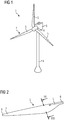
- Fig. 1 shows a wind turbine 1.
- the wind turbine 1 comprises a rotor 2 connected to a generator (not shown) arranged inside a nacelle 3.
- the nacelle 3 is arranged at the upper end of a tower 4 of the wind turbine 1.
- the rotor 2 comprises three wind turbine blades 5.
- the wind turbine blades 5 are connected to a hub 6 of the wind turbine 1.
- Rotors 2 of this kind may have diameters ranging from, for example, 30 to 200 meters or even more.
- the wind turbine blades 5 are subjected to high wind loads.
- the wind turbine blades 5 need to be lightweight.
- wind turbine blades 5 in modern wind turbines 1 are manufactured from fiber-reinforced composite materials. Therein, glass fibers are generally preferred over carbon fibers for cost reasons. Oftentimes, glass fibers in the form of unidirectional fiber mats are used.
- Fig. 2 shows a wind turbine blade 5.
- the wind turbine blade 5 comprises an aerodynamically designed portion 7 which is shaped for optimum exploitation of the wind energy and a blade root 8 for connecting the wind turbine blade 5 to the hub 6. Further, the wind turbine blade 5 comprises a blade tip 9 which is arranged averted from the blade root 8. The wind turbine blade 5 extends in a longitudinal direction L.
- Fig. 3 shows a cross-sectional view III-III from Fig. 2 .
- the wind turbine blade 5 comprises an outer blade shell 10 comprising a first half-shell 11 and a second half-shell 12 which are connected together at one side 13 of the wind turbine blade 5, in particular at a trailing edge, and at the other side 14 of the wind turbine blade 5, in particular at a leading edge, to form the outer shell 10 of the wind turbine blade 5.
- the blade shell 10 may comprise composite fiber material. Further, the first half-shell 11 and the second half-shell 12 may be glued together. Alternatively, the blade shell 10 may be provided as a one-piece element.
- the first half-shell 11 comprises an inner surface 15 and the second half-shell 12 comprises an inner surface 16 being opposite to each other, wherein an inner space 17 of the wind turbine blade 5 is defined by the inner surfaces 15, 16.
- a web 18 is located inside the inner space 17 extending from the inner surface 15 of the first half-shell 11 to the inner surface 16 of the second half-shell 12.
- the wind turbine blade 5 further comprises a first beam 19 connected to the first half-shell 11 and a second beam 20 connected to the second half-shell 12.
- the first and the second beam 19, 20 are electrically conductive and extend along the longitudinal direction L.
- the web 18 is located between the first beam 19 and the second beam 20, wherein the web 18 and the beams 19, 20 are forming an I-shaped cross section.
- the web 18 and the beams 19, 20 are forming a support structure preventing breaking or crippling of the wind turbine blade 5.
- the web 18 extends along the longitudinal direction L of the blade 5.
- a lightning conductor 21 is provided extending along the longitudinal direction L and being attached to the web 18.
- a ply 22 comprising carbon fibers is provided.
- the ply 22 is attached to both the lightning conductor 21 and the first beam 19 to electrically connect the lightning conductor 21 to the first beam 19.
- the ply 22 is also connected to the second beam 20.
- a further ply 23 is provided comprising carbon fibers electrically connecting the first beam 19 with the second beam 20.
- the further ply 23 is arranged parallel to the ply 22 and is attached to the first beam 19 and the second beam 20.
- the further ply 23 is arranged at a side 24 of the web 18 which is averted from the ply 22.
- the blade 5 may be provided without the further ply 23.
- Fig. 4 shows a detail view IV from Fig. 3 . Contrary to Fig. 3 the further ply 23 (see Fig. 3 ) is not provided. A surface 25 of the first beam 19 which faces the web 18 is divided by the web 18 in a first part 26 (left part) and a second part 27 (right part). The ply 22 only covers the first part 26 of all surfaces of the beam 19 and is connected thereto. “Cover” may mean that the ply 22 is directly or indirectly connected to the beam 19 and that an overlap is provided.
- the web 18 may be connected to the first beam 19 and/or the second beam 20 by means of a connecting element serving as a receptacle for the web 18 (not shown).
- Fig. 5 shows a detail view IV from Fig. 3 of a further embodiment of the wind turbine blade 5.
- the ply 22 is wrapped around the beam 19 such that only the part 26, a surface 28 which is averted from the surface 25, and a surface 29 connecting the part 26 and the surface 28 are covered by the ply 22.
- the ply 22 may be wrapped completely around the beam 19 such that also the part 27 of the surface 25 is covered by the ply 22.
- Fig. 6 shows a detail view IV from Fig. 3 of a further embodiment of the wind turbine blade 5.
- the ply 22 is attached to the first beam 19 by means of a conductive layer 30, in particular a metallic or carbon layer.
- a metallic layer may comprise metallic cooper and/or an aluminum mesh.
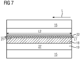
- Fig. 7 shows a cross-sectional view VII-VII of Fig. 4 .
- the lightning conductor 21 has a length L1 extending essentially from the blade tip 9 to the blade root 8 (see Fig. 2 ). Further, the ply 22 has a length L2 in longitudinal direction L. The ply 22 is attached to the lightning conductor 21 and the first beam 19 along the ply's 22 total length L2.
- the ply 22 has the length L2 being at least 10%, 20%, 30%, 40%, 50%, 60%, 70%, 80%, 90% or 100% of a length L1 of the lightning conductor 21.
- Fig. 8 shows a partial cross-sectional view of a further embodiment of the wind turbine blade 1.
- a second lightning conductor 31 extending along the longitudinal direction L of the blade 5 is provided, wherein the first lightening conductor 21 is arranged at one side 32 of the web 18 and the second lightening conductor 31 is arranged at the other side 35 of the web 18 being averted from the one side 32.
- the second lighting conductor 31 is attached to the web 18 and the further ply 23.
- the second lightning conductor 31 is covered by the further ply 23.
- the further ply 23 is arranged as described in Fig. 3 .
- Fig. 9 shows a partial cross-sectional view of a further embodiment of the wind turbine blade 1.
- the ply 22 contacts the complete surface 25, wherein the ply 22 is bended at an edge 33 of the beam 19 such that the part 27 is covered two-ply by the ply 22 and extends further towards the lightening conductor 21.
- the web 18 is connected to the beam 19 by means of the ply 22.
- Fig. 10 shows a partial cross-sectional view of a further embodiment of the wind turbine blade 1.
- the beam 19 is connected to the half-shell 11 by means of a ply 34, in particular having carbon fibers and being electrically conductive.
- the ply 34 covers the complete surface 28 and is connected thereto.
- the ply 34 attaches the ply 22 and the ply 23.
- the beam 20 is connected to the half-shell 12 by means of a ply 36, in particular having carbon fibers and being electrically conductive.
- the ply 36 may be provided equally to the ply 34.
- the ply 22 may be connected to the second beam 20 in the same way as to the first beam 19.
Landscapes
- Engineering & Computer Science (AREA)
- Life Sciences & Earth Sciences (AREA)
- Sustainable Development (AREA)
- Sustainable Energy (AREA)
- Chemical & Material Sciences (AREA)
- Combustion & Propulsion (AREA)
- Mechanical Engineering (AREA)
- General Engineering & Computer Science (AREA)
- Wind Motors (AREA)
- Elimination Of Static Electricity (AREA)
Abstract
Description
- The present invention relates to a wind turbine blade for a wind turbine and a wind turbine.
- Modern wind turbine rotor blades are built from fiber-reinforced plastics. A rotor blade typically comprises an airfoil having a rounded leading edge and a sharp trailing edge. The rotor blade is connected with its blade root to a hub of the wind turbine. Further, the rotor blade is connected to the hub by means of a pitch bearing that allows a pitch movement of the rotor blade. Long rotor blades experiences high wind forces.
- Rotor blades may be made of two half-shells connected to each other. Further, a web, in particular a shear web, may be arranged between the two half-shells to reinforce the rotor blade. The shear web may be arranged between two beams, in particular spar caps, and may be connected thereto.
- Rotor blades are the most exposed part of the wind turbine with respect to lightning strikes. Therefore, lightning protection systems (LPS) may be provided. A lightning protection system may comprise a lightening conductor which may be connected to the web and which may extend along a longitudinal direction of the web. The lightening conductor may be electrically connected to a grounding system of the wind turbine blade. Further, attachment points for the lightning - commonly known as receptors - may be arranged along a blade surface and connected to the lightening conductor.
- When a lightning strike is intercepted by the lightning protection system, the electrical current is transferred to the ground by means of the lightning conductor. However, flash-overs between the lightning conductor and the beams which for example may comprise carbon fibers being electrical conductive may occur since the beams may provide an alternative path to the ground. Moreover, mutual induction may cause currents in the beams. These effects may cause structural damage to the beams and possibly catastrophic failure of the blade. To prevent damage of the beams electrical connections between the lightning conductor and the beams may be provided.
- It is one object of the present invention to provide an improved wind turbine blade.
- Accordingly, a wind turbine blade for a wind turbine is provided. The wind turbine blade comprises a web extending along a longitudinal direction of the blade, an electrically conductive beam extending along the longitudinal direction of the blade and being connected to the web, a lightning conductor extending along the longitudinal direction of the blade and being attached to the web, and a ply comprising carbon fibers, wherein the ply is attached to both the lightning conductor and the beam to electrically connect the lightning conductor to the beam.
- In contrast to known wind turbine blades, an extensive and continuous electrical connection between the lightning conductor and the beam is provided. This has the advantage that e.g. a plurality of cables electrically connecting the lightning conductor with the beam may be substituted. The ply may be designed as structural improvement of the web. Hence, only minor adjustments of a wind turbine blade manufacturing process are required. Thus, a production of such a wind turbine blade is simplified. Further, malfunctions of such an electrical connection may be reduced since the ply provides a large contact surface to the lightning conductor and to the beam. Furthermore, a critical connection from metal to carbon prone to arching is provided away from the beam and, hence, minimizing the risk of structurally critical damage at the beam. Moreover, the ply serves as an effective reinforcement element since a ply having carbon fibers is lightweight compared to a ply made of a metal.
- The beam may comprise carbon fibers and/or may be e.g. a spar cap. In particular, the beam may be made of a composite material, in particular carbon-fiber-reinforced polymer (CFRP), wherein the electrical conductivity may be achieved, e.g. merely, by means of the carbon fibers. Further, the beam may be a first beam and/or a first spar cap.
- The web may be e.g. a shear web. Further, the web may be a support structure of the wind turbine blade. Preferably, the web is configured to prevent crippling or buckling of the wind turbine blade. Preferably, the web is forming a wall, rib or stringer arranged between an inner surface of a first half-hell of an outer blade shell and an inner surface of a second half-shell of the outer blade shell. Preferably, the web is provided as a one-piece body, e.g. made of composite material, in particular fiber reinforced plastic material, and/or wood (e.g. plywood). Preferably, the web is not electrically conductive and/or insulated.
- Preferably, the wind turbine blade comprises receptors for the lightning which are arranged along an outer surface of the outer blade shell and which are electrically connected to the lightening conductor.
- The "ply" may mean a structural element having a length, a width, and a thickness, wherein an amount of the length and an amount the width is at least 5, 10, 15, 20, 30, 40 or more times larger than an amount of the thickness. The ply may comprise a plurality of ply segments being arranged side by side, wherein each ply segment is attached to the lightning conductor and the beam. Preferably, the ply segments may be provided at intervals. In particular, gaps between ply segments (distance between the ply segments) may be provided. Additionally or alternatively, overlaps between the ply segments may be provided. Alternatively, the ply may be a one-piece element. In particular, the ply may be a carbon ply.
- The lightening conductor may be a down conductor. The lightening conductor may comprise metal. In particular, two or more lightening conductors may be provided which are arranged parallel each electrically connected to the beam. Preferably, only one lightning conductor is provided.
- Preferably, a connection between the ply and the beam and/or the ply and the lightning conductor is made by means of vacuum infusion of the blade. Thus, preferably no additional connections need to be done after a blade casting. Preferably, the carbon fibers of the ply which are electrically conductive are attached to carbon fibers of the beam such that a current may flow from the lightning conductor to the beam.
- According to an embodiment, the wind turbine blade comprises a blade tip and a blade root, wherein the lightning conductor extends from the blade tip to the blade root, and wherein the ply has a length being at least 1%, 10%, 20%, 30%, 40%, 50%, 60%, 70%, 80%, 90% or 100% of a length of the lightning conductor.
- This has the advantage that a significant amount of electrical power may be transferred by the ply. Preferably, the blade tip and the blade root are comprised by the outer blade shell of the wind turbine blade in particular having the first and the second half-shell.
- According to a further embodiment, the ply is attached to the lightning conductor and the beam along the ply's total length.
- This has the advantage that a reliable contact between the ply and the lightning conductor and the ply and the beam may be provided. Moreover, a current density in a connection is minimized, in particular by means of a continuous equipotential bonding, enabling a simple design of a connection interface.
- According to a further embodiment, the ply is attached to the beam by means of a conductive layer, in particular a metallic layer, a carbon ply portion or a hybrid carbon-metallic mat.
- This has the advantage that the electrical conductivity of the connection between the ply and the beam may be improved. Preferably, the conductive layer comprises metallic copper and/or an aluminum mesh. Alternatively, the conductive layer may be a carbon layer.
- According to a further embodiment, the wind turbine blade comprises a further beam having carbon fibers, being electrically conductive, and which is connected to the web, wherein the ply is attached to the further beam for electrically connecting the lightning conductor to the further beam.
- This has the advantage that flash-overs between the lightning conductor and the further beam may be avoided. The further beam may be a second spar cap and/or a second beam.
- According to a further embodiment, the web is located between the beam and the further beam forming an I-shaped cross section.
- This has the advantage that a stiff I-profile may be provided inside the blade shell such that a stiff and lightweight wind turbine blade may be provided. Preferably, a further web may be provided arranged parallel to the web and in particular connected to the beam and the further beam.
- According to a further embodiment, the wind turbine blade comprises a further ply having carbon fibers electrically connecting the beam to the further beam, which is arranged parallel to the ply, and which is attached to the beam and the further beam.
- This has the advantage that a further electrical connection between the beam and the further beam reinforcing the web may be provided. In particular, a second lightning conductor extending along the longitudinal direction of the blade may be provided, wherein the first lightening conductor is arranged at one side of the web and the second lightening conductor is arranged at the other side of the web being averted from the one side. The second lightning conductor may be attached to the web and the further ply. Preferably, the second lighting conductor is covered by the further ply.
- According to a further embodiment, in a cross-sectional view the ply is wrapped around the beam.
- This has the advantage that the electrical connection between the ply and the beam may be improved. Preferably, at least 30%, 40%, 50%, 60%, 70%, 80% or more of an outer surface of the beam is covered by the ply.
- According to a further embodiment, the wind turbine blade comprises an outer blade shell, wherein the beam is connected to the outer blade shell.
- Preferably, the beam is connected to the first half-shell and the further beam is connected to the second half-shell. Preferably, the first half-shell and the second half-shell are connected together or may be provided as a one-piece element.
- Further, a wind turbine having such a wind turbine blade is provided.
- "Wind turbine" presently refers to an apparatus converting the wind's kinetic energy into rotational energy, which may again be converted to electrical energy by the apparatus.
- Further possible implementations or alternative solutions of the invention also encompass combinations - that are not explicitly mentioned herein - of features described above or below with regard to the embodiments. The person skilled in the art may also add individual or isolated aspects and features to the most basic form of the invention.
- Further embodiments, features and advantages of the present invention will become apparent from the subsequent description and dependent claims, taken in conjunction with the accompanying drawings, in which:
-
Fig. 1 shows a perspective view of a wind turbine according to one embodiment; -
Fig. 2 shows a perspective view of a wind turbine blade of the wind turbine according toFig. 1 ; -
Fig. 3 shows a cross-sectional view III-III fromFig. 2 ; -
Fig. 4 shows a detail view IV fromFig. 3 in accordance with one embodiment; -
Fig. 4 shows a detail view IV fromFig. 3 in accordance with a further embodiment; -
Fig. 6 shows a detail view IV fromFig. 3 in accordance with a further embodiment; -
Fig. 7 shows a cross-sectional view VII-VII fromFig. 4 ; -
Fig. 8 shows a partial cross-sectional view of a further embodiment of the wind turbine blade; -
Fig. 9 shows a partial cross-sectional view of a further embodiment of the wind turbine blade; and -
Fig. 10 shows a partial cross-sectional view of a further embodiment of the wind turbine blade. - In the Figures, like reference numerals designate like or functionally equivalent elements, unless otherwise indicated.
-
Fig. 1 shows a wind turbine 1. The wind turbine 1 comprises arotor 2 connected to a generator (not shown) arranged inside a nacelle 3. The nacelle 3 is arranged at the upper end of atower 4 of the wind turbine 1. - The
rotor 2 comprises threewind turbine blades 5. Thewind turbine blades 5 are connected to ahub 6 of the wind turbine 1.Rotors 2 of this kind may have diameters ranging from, for example, 30 to 200 meters or even more. Thewind turbine blades 5 are subjected to high wind loads. At the same time, thewind turbine blades 5 need to be lightweight. For these reasons,wind turbine blades 5 in modern wind turbines 1 are manufactured from fiber-reinforced composite materials. Therein, glass fibers are generally preferred over carbon fibers for cost reasons. Oftentimes, glass fibers in the form of unidirectional fiber mats are used. -
Fig. 2 shows awind turbine blade 5. Thewind turbine blade 5 comprises an aerodynamically designedportion 7 which is shaped for optimum exploitation of the wind energy and ablade root 8 for connecting thewind turbine blade 5 to thehub 6. Further, thewind turbine blade 5 comprises ablade tip 9 which is arranged averted from theblade root 8. Thewind turbine blade 5 extends in a longitudinal direction L. -
Fig. 3 shows a cross-sectional view III-III fromFig. 2 . Thewind turbine blade 5 comprises anouter blade shell 10 comprising a first half-shell 11 and a second half-shell 12 which are connected together at oneside 13 of thewind turbine blade 5, in particular at a trailing edge, and at theother side 14 of thewind turbine blade 5, in particular at a leading edge, to form theouter shell 10 of thewind turbine blade 5. Theblade shell 10 may comprise composite fiber material. Further, the first half-shell 11 and the second half-shell 12 may be glued together. Alternatively, theblade shell 10 may be provided as a one-piece element. - The first half-
shell 11 comprises aninner surface 15 and the second half-shell 12 comprises aninner surface 16 being opposite to each other, wherein aninner space 17 of thewind turbine blade 5 is defined by theinner surfaces web 18 is located inside theinner space 17 extending from theinner surface 15 of the first half-shell 11 to theinner surface 16 of the second half-shell 12. Thewind turbine blade 5 further comprises afirst beam 19 connected to the first half-shell 11 and asecond beam 20 connected to the second half-shell 12. The first and thesecond beam - The
web 18 is located between thefirst beam 19 and thesecond beam 20, wherein theweb 18 and thebeams web 18 and thebeams wind turbine blade 5. Theweb 18 extends along the longitudinal direction L of theblade 5. Further, alightning conductor 21 is provided extending along the longitudinal direction L and being attached to theweb 18. Furthermore, aply 22 comprising carbon fibers is provided. - The
ply 22 is attached to both thelightning conductor 21 and thefirst beam 19 to electrically connect thelightning conductor 21 to thefirst beam 19. Preferably, theply 22 is also connected to thesecond beam 20. Moreover, afurther ply 23 is provided comprising carbon fibers electrically connecting thefirst beam 19 with thesecond beam 20. The further ply 23 is arranged parallel to theply 22 and is attached to thefirst beam 19 and thesecond beam 20. The further ply 23 is arranged at aside 24 of theweb 18 which is averted from theply 22. - Alternatively, the
blade 5 may be provided without thefurther ply 23. -
Fig. 4 shows a detail view IV fromFig. 3 . Contrary toFig. 3 the further ply 23 (seeFig. 3 ) is not provided. Asurface 25 of thefirst beam 19 which faces theweb 18 is divided by theweb 18 in a first part 26 (left part) and a second part 27 (right part). Theply 22 only covers thefirst part 26 of all surfaces of thebeam 19 and is connected thereto. "Cover" may mean that theply 22 is directly or indirectly connected to thebeam 19 and that an overlap is provided. - Furthermore, the
web 18 may be connected to thefirst beam 19 and/or thesecond beam 20 by means of a connecting element serving as a receptacle for the web 18 (not shown). -
Fig. 5 shows a detail view IV fromFig. 3 of a further embodiment of thewind turbine blade 5. Contrary toFig. 4 , theply 22 is wrapped around thebeam 19 such that only thepart 26, asurface 28 which is averted from thesurface 25, and asurface 29 connecting thepart 26 and thesurface 28 are covered by theply 22. Alternatively (not shown), theply 22 may be wrapped completely around thebeam 19 such that also thepart 27 of thesurface 25 is covered by theply 22. -
Fig. 6 shows a detail view IV fromFig. 3 of a further embodiment of thewind turbine blade 5. Contrary toFig. 4 , theply 22 is attached to thefirst beam 19 by means of aconductive layer 30, in particular a metallic or carbon layer. Such a metallic layer may comprise metallic cooper and/or an aluminum mesh. -
Fig. 7 shows a cross-sectional view VII-VII ofFig. 4 . Thelightning conductor 21 has a length L1 extending essentially from theblade tip 9 to the blade root 8 (seeFig. 2 ). Further, theply 22 has a length L2 in longitudinal direction L. The ply 22 is attached to thelightning conductor 21 and thefirst beam 19 along the ply's 22 total length L2. - In particular, the
ply 22 has the length L2 being at least 10%, 20%, 30%, 40%, 50%, 60%, 70%, 80%, 90% or 100% of a length L1 of thelightning conductor 21. -
Fig. 8 shows a partial cross-sectional view of a further embodiment of the wind turbine blade 1. In contrast toFig. 4 , asecond lightning conductor 31 extending along the longitudinal direction L of theblade 5 is provided, wherein thefirst lightening conductor 21 is arranged at oneside 32 of theweb 18 and thesecond lightening conductor 31 is arranged at theother side 35 of theweb 18 being averted from the oneside 32. Thesecond lighting conductor 31 is attached to theweb 18 and thefurther ply 23. Thesecond lightning conductor 31 is covered by thefurther ply 23. The further ply 23 is arranged as described inFig. 3 . -
Fig. 9 shows a partial cross-sectional view of a further embodiment of the wind turbine blade 1. In contrast toFig. 4 , theply 22 contacts thecomplete surface 25, wherein theply 22 is bended at anedge 33 of thebeam 19 such that thepart 27 is covered two-ply by theply 22 and extends further towards the lighteningconductor 21. Further, theweb 18 is connected to thebeam 19 by means of theply 22. -
Fig. 10 shows a partial cross-sectional view of a further embodiment of the wind turbine blade 1. In contrast toFig. 3 , thebeam 19 is connected to the half-shell 11 by means of aply 34, in particular having carbon fibers and being electrically conductive. Theply 34 covers thecomplete surface 28 and is connected thereto. Theply 34 attaches theply 22 and theply 23. In particular, thebeam 20 is connected to the half-shell 12 by means of aply 36, in particular having carbon fibers and being electrically conductive. Theply 36 may be provided equally to theply 34. - Although the present invention has been described in accordance with preferred embodiments, it is obvious for the person skilled in the art that modifications are possible in all embodiments. In particular the
ply 22 may be connected to thesecond beam 20 in the same way as to thefirst beam 19.
Claims (10)
- A wind turbine blade (5) for a wind turbine (1), comprising
a web (18) extending along a longitudinal direction (L) of the blade (5),
an electrically conductive beam (19) extending along the longitudinal direction (L) of the blade (5) and being connected to the web (18),
a lightning conductor (21) extending along the longitudinal direction (L) of the blade (5) and being attached to the web (18), and
a ply (22) comprising carbon fibers, wherein the ply (22) is attached to both the lightning conductor (21) and the beam (19) to electrically connect the lightning conductor (21) to the beam (19). - The wind turbine blade according to claim 1,
having a blade tip (9) and a blade root (8), wherein the lightning conductor (21) extends from the blade tip (9) to the blade root (8), and wherein the ply (22) has a length (L2) being at least 1%, 10%, 20%, 30%, 40%, 50%, 60%, 70%, 80%, 90% or 100% of a length (L1) of the lightning conductor (21). - The wind turbine blade according to claim 1 or 2,
wherein the ply (21) is attached to the lightning conductor (21) and the beam (19) along the ply's (22) total length (L2). - The wind turbine blade according to one of claims 1 - 3, wherein the ply (22) is attached to the beam (19) by means of a conductive layer (30), in particular a metallic layer, a carbon ply portion or a hybrid carbon-metallic mat.
- The wind turbine blade according to one of claims 1 - 4, having a further beam (20) comprising carbon fibers, being electrically conductive, and which is connected to the web (18), wherein the ply (22) is attached to the further beam (20) for electrically connecting the lightning conductor (21) to the further beam (20).
- The wind turbine blade according to claim 5,
wherein the web (18) is located between the beam (19) and the further beam (20) forming an I-shaped cross section. - The wind turbine blade according to claim 5 or 6,
having a further ply (23) comprising carbon fibers electrically connecting the beam (19) to the further beam (20), which is arranged parallel to the ply (22), and which is attached to the beam (19) and the further beam (20). - The wind turbine blade according to one of claims 1 - 7, wherein in a cross-sectional view the ply (22) is wrapped around the beam.
- The wind turbine blade according to one of claims 1 - 8, having an outer blade shell (10), wherein the beam (19) is connected to the outer blade shell (10).
- A wind turbine (1) having a wind turbine blade (5) according to one of claims 1 - 9.
Priority Applications (5)
| Application Number | Priority Date | Filing Date | Title |
|---|---|---|---|
| ES17201644T ES2955528T3 (en) | 2017-11-14 | 2017-11-14 | wind turbine blade and wind turbine |
| DK17201644.6T DK3483424T3 (en) | 2017-11-14 | 2017-11-14 | WINDMILL BLADE AND WINDMILL |
| EP17201644.6A EP3483424B1 (en) | 2017-11-14 | 2017-11-14 | A wind turbine blade and a wind turbine |
| US16/185,241 US11248587B2 (en) | 2017-11-14 | 2018-11-09 | Wind turbine blade and a wind turbine |
| CN201811353145.4A CN109779829A (en) | 2017-11-14 | 2018-11-14 | Wind turbine blades and wind turbines |
Applications Claiming Priority (1)
| Application Number | Priority Date | Filing Date | Title |
|---|---|---|---|
| EP17201644.6A EP3483424B1 (en) | 2017-11-14 | 2017-11-14 | A wind turbine blade and a wind turbine |
Publications (2)
| Publication Number | Publication Date |
|---|---|
| EP3483424A1 true EP3483424A1 (en) | 2019-05-15 |
| EP3483424B1 EP3483424B1 (en) | 2023-07-26 |
Family
ID=60327154
Family Applications (1)
| Application Number | Title | Priority Date | Filing Date |
|---|---|---|---|
| EP17201644.6A Active EP3483424B1 (en) | 2017-11-14 | 2017-11-14 | A wind turbine blade and a wind turbine |
Country Status (5)
| Country | Link |
|---|---|
| US (1) | US11248587B2 (en) |
| EP (1) | EP3483424B1 (en) |
| CN (1) | CN109779829A (en) |
| DK (1) | DK3483424T3 (en) |
| ES (1) | ES2955528T3 (en) |
Cited By (6)
| Publication number | Priority date | Publication date | Assignee | Title |
|---|---|---|---|---|
| CN113074090A (en) * | 2021-03-31 | 2021-07-06 | 株洲时代新材料科技股份有限公司 | Carbon-glass hybrid wind power blade crossbeam and preparation method thereof |
| EP3877643A1 (en) * | 2018-11-06 | 2021-09-15 | Blade Dynamics Limited | Spar structure with integrated down conductor element for lightning protection system |
| US11181095B2 (en) | 2019-04-25 | 2021-11-23 | Siemens Gamesa Renewable Energy A/S | Spar cap, wind turbine blade, wind turbine and method for manufacturing a spar cap |
| US11353003B2 (en) | 2019-04-03 | 2022-06-07 | Siemens Gamesa Renewable Energy A/S | Wind turbine blade and wind turbine |
| US12104577B2 (en) | 2019-05-09 | 2024-10-01 | Siemens Gamesa Renewable Energy A/S | Blade for a wind turbine and wind turbine |
| US12404839B2 (en) | 2020-05-14 | 2025-09-02 | Siemens Gamesa Renewable Energy A/S | Wind turbine blade and wind turbine with a down conductor spar cap |
Families Citing this family (14)
| Publication number | Priority date | Publication date | Assignee | Title |
|---|---|---|---|---|
| EP3597911B1 (en) * | 2018-07-17 | 2021-08-25 | Siemens Gamesa Renewable Energy A/S | A wind turbine blade and a wind turbine |
| CN114127410A (en) * | 2018-10-25 | 2022-03-01 | Lm风力发电公司 | Lightning protection of segmented wind turbine blades |
| WO2020084050A1 (en) * | 2018-10-25 | 2020-04-30 | Lm Wind Power A/S | Lightning protection of a sectioned wind turbine blade |
| GB201817599D0 (en) * | 2018-10-29 | 2018-12-12 | Blade Dynamics Ltd | Manufacturing of segmented wind turbine blade |
| DK3670169T3 (en) * | 2018-12-21 | 2022-11-07 | Siemens Gamesa Renewable Energy As | Process for vacuum-assisted resin injection molding |
| EP3719298B1 (en) * | 2019-04-05 | 2023-01-11 | Siemens Gamesa Renewable Energy A/S | Beam for a wind turbine blade and method for manufacturing therefor |
| EP3885573B1 (en) * | 2020-03-27 | 2022-10-12 | Nordex Energy SE & Co. KG | Bar for reinforcing a wind energy system rotor blade |
| EP4019766A1 (en) * | 2020-12-23 | 2022-06-29 | Polytech A/S | A conductive connection |
| FI130757B1 (en) * | 2021-01-12 | 2024-02-27 | Wicetec Oy | A wind turbine blade comprising a potential control arrangement |
| CN112879248B (en) * | 2021-03-23 | 2024-03-22 | 国电联合动力技术(保定)有限公司 | Wind power blade lightning-protection branch point and pre-bending position lightning-protection structure and manufacturing method |
| US20240254960A1 (en) * | 2021-04-28 | 2024-08-01 | Blade Dynamics Limited | Manufacturing of segmented wind turbine blade |
| CN113958447B (en) * | 2021-11-10 | 2022-07-22 | 常州市宏发纵横新材料科技股份有限公司 | Modular wind power blade chord direction blocking connection structure |
| CN118414491A (en) * | 2021-12-16 | 2024-07-30 | Lm风力发电公司 | Lightning protection systems for wind turbine blades |
| DK4234928T3 (en) * | 2022-02-25 | 2024-11-04 | Siemens Gamesa Renewable Energy As | WINDMILL ROTOR BLADE AND WINDMILL |
Citations (5)
| Publication number | Priority date | Publication date | Assignee | Title |
|---|---|---|---|---|
| WO2005050808A1 (en) * | 2003-10-31 | 2005-06-02 | Vestas Wind Systems A/S | Member for potential equalising |
| EP1826402A1 (en) * | 2004-11-11 | 2007-08-29 | Gamesa Innovation And Technology, S.L. | Lightning conductor system for wind generator blades comprising carbon fibre laminates |
| EP2110552A1 (en) * | 2008-04-15 | 2009-10-21 | Siemens Aktiengesellschaft | Wind turbine blade with an integrated lightning conductor and method for manufacturing the same |
| US20120315147A1 (en) * | 2011-06-10 | 2012-12-13 | Philipp Rindt | Wind turbine component having an electrical line embedded in a laminate and method for making the same |
| US20150292479A1 (en) * | 2014-04-10 | 2015-10-15 | Nordex Energy Gmbh | Spar cap assembly for a wind turbine rotor blade |
Family Cites Families (11)
| Publication number | Priority date | Publication date | Assignee | Title |
|---|---|---|---|---|
| ES2255436B1 (en) | 2004-11-11 | 2007-07-01 | Gamesa Eolica, S.A. | PARARRAYOS SYSTEM FOR AEROGENERATOR SHOVEL WITH CARBON FIBER LAMINATES. |
| US8182227B2 (en) * | 2008-02-01 | 2012-05-22 | General Electric Company | Wind turbine blade with lightning receptor |
| DK2318197T3 (en) | 2008-06-20 | 2016-07-18 | Vestas Wind Sys As | A process for the preparation of a spar for a wind turbine from elements of geometrically well-defined joining surface parts and the related bar |
| ES2396839B1 (en) | 2010-11-30 | 2014-01-02 | Gamesa Innovation & Technology, S.L. | PARARRAYOS SYSTEM FOR AEROGENERATOR SHOVEL WITH CARBON FIBER LAMINATES. |
| US20190195203A1 (en) * | 2011-12-09 | 2019-06-27 | Mitsubishi Heavy Industries, Ltd. | Wind turbine blade for a wind turbine |
| DK2930355T3 (en) | 2014-04-10 | 2018-11-26 | Nordex Energy Gmbh | Wind turbine rotor blade with a lightning arrester and a potential equalizer |
| US9920739B2 (en) * | 2014-12-18 | 2018-03-20 | General Electric Company | System and method for securing a conductive cable within a wind turbine rotor blade |
| ES2589185B1 (en) * | 2015-05-08 | 2017-09-18 | Gamesa Innovation & Technology, S.L. | Lightning rod system for wind turbine blades with conductive structural components |
| US20170058869A1 (en) * | 2015-08-27 | 2017-03-02 | General Electric Company | Conduit assembly for a lightning protection cable of a wind turbine rotor blade |
| US10648456B2 (en) * | 2016-10-21 | 2020-05-12 | General Electric Company | Organic conductive elements for deicing and lightning protection of a wind turbine rotor blade |
| US11486366B2 (en) * | 2017-05-09 | 2022-11-01 | Siemens Gamesa Renewable Energy A/S | Lightning protection system for a wind turbine blade |
-
2017
- 2017-11-14 DK DK17201644.6T patent/DK3483424T3/en active
- 2017-11-14 EP EP17201644.6A patent/EP3483424B1/en active Active
- 2017-11-14 ES ES17201644T patent/ES2955528T3/en active Active
-
2018
- 2018-11-09 US US16/185,241 patent/US11248587B2/en active Active
- 2018-11-14 CN CN201811353145.4A patent/CN109779829A/en active Pending
Patent Citations (5)
| Publication number | Priority date | Publication date | Assignee | Title |
|---|---|---|---|---|
| WO2005050808A1 (en) * | 2003-10-31 | 2005-06-02 | Vestas Wind Systems A/S | Member for potential equalising |
| EP1826402A1 (en) * | 2004-11-11 | 2007-08-29 | Gamesa Innovation And Technology, S.L. | Lightning conductor system for wind generator blades comprising carbon fibre laminates |
| EP2110552A1 (en) * | 2008-04-15 | 2009-10-21 | Siemens Aktiengesellschaft | Wind turbine blade with an integrated lightning conductor and method for manufacturing the same |
| US20120315147A1 (en) * | 2011-06-10 | 2012-12-13 | Philipp Rindt | Wind turbine component having an electrical line embedded in a laminate and method for making the same |
| US20150292479A1 (en) * | 2014-04-10 | 2015-10-15 | Nordex Energy Gmbh | Spar cap assembly for a wind turbine rotor blade |
Cited By (8)
| Publication number | Priority date | Publication date | Assignee | Title |
|---|---|---|---|---|
| EP3877643A1 (en) * | 2018-11-06 | 2021-09-15 | Blade Dynamics Limited | Spar structure with integrated down conductor element for lightning protection system |
| US11994112B2 (en) | 2018-11-06 | 2024-05-28 | Blade Dynamics Limited | Spar structure with integrated down conductor element for lightning protection system |
| US11353003B2 (en) | 2019-04-03 | 2022-06-07 | Siemens Gamesa Renewable Energy A/S | Wind turbine blade and wind turbine |
| US11181095B2 (en) | 2019-04-25 | 2021-11-23 | Siemens Gamesa Renewable Energy A/S | Spar cap, wind turbine blade, wind turbine and method for manufacturing a spar cap |
| US12104577B2 (en) | 2019-05-09 | 2024-10-01 | Siemens Gamesa Renewable Energy A/S | Blade for a wind turbine and wind turbine |
| US12404839B2 (en) | 2020-05-14 | 2025-09-02 | Siemens Gamesa Renewable Energy A/S | Wind turbine blade and wind turbine with a down conductor spar cap |
| CN113074090A (en) * | 2021-03-31 | 2021-07-06 | 株洲时代新材料科技股份有限公司 | Carbon-glass hybrid wind power blade crossbeam and preparation method thereof |
| CN113074090B (en) * | 2021-03-31 | 2022-12-09 | 株洲时代新材料科技股份有限公司 | Carbon-glass hybrid wind power blade crossbeam and preparation method thereof |
Also Published As
| Publication number | Publication date |
|---|---|
| DK3483424T3 (en) | 2023-09-04 |
| ES2955528T3 (en) | 2023-12-04 |
| US20190145383A1 (en) | 2019-05-16 |
| CN109779829A (en) | 2019-05-21 |
| EP3483424B1 (en) | 2023-07-26 |
| US11248587B2 (en) | 2022-02-15 |
Similar Documents
| Publication | Publication Date | Title |
|---|---|---|
| US11248587B2 (en) | Wind turbine blade and a wind turbine | |
| EP3594494B1 (en) | A wind turbine blade and a wind turbine | |
| CN113316684B (en) | Equipotential bonding of wind turbine rotor blades | |
| CN108700041B (en) | Wind turbine blade and potential equalising system | |
| EP3020958B1 (en) | Spar cap for a wind turbine rotor blade | |
| US11746744B2 (en) | Equipotential bonding of wind turbine rotor blade | |
| CN113316683A (en) | Equipotential bonding of wind turbine rotor blades | |
| CN111852752B (en) | Spar cap, wind turbine blade, wind turbine and method for manufacturing spar cap | |
| US20230407848A1 (en) | A spar cap assembly for a wind turbine blade with a lightning protection system | |
| US11795920B2 (en) | Lightning protection for a wind turbine blade | |
| CN110725774A (en) | Wind turbine blades and wind turbines | |
| US20250198392A1 (en) | Lightning protection system for a wind turbine blade | |
| EP3870838A1 (en) | Lightning protection of a sectioned wind turbine blade | |
| CN120265878A (en) | Lightning protection systems for wind turbine rotor blades | |
| US12281641B2 (en) | Wind turbine blade, a wind turbine and a method for manufacturing a wind turbine blade | |
| US12270372B2 (en) | Modular wind turbine blade with lightning protection system |
Legal Events
| Date | Code | Title | Description |
|---|---|---|---|
| PUAI | Public reference made under article 153(3) epc to a published international application that has entered the european phase |
Free format text: ORIGINAL CODE: 0009012 |
|
| STAA | Information on the status of an ep patent application or granted ep patent |
Free format text: STATUS: THE APPLICATION HAS BEEN PUBLISHED |
|
| AK | Designated contracting states |
Kind code of ref document: A1 Designated state(s): AL AT BE BG CH CY CZ DE DK EE ES FI FR GB GR HR HU IE IS IT LI LT LU LV MC MK MT NL NO PL PT RO RS SE SI SK SM TR |
|
| AX | Request for extension of the european patent |
Extension state: BA ME |
|
| STAA | Information on the status of an ep patent application or granted ep patent |
Free format text: STATUS: REQUEST FOR EXAMINATION WAS MADE |
|
| 17P | Request for examination filed |
Effective date: 20191114 |
|
| RBV | Designated contracting states (corrected) |
Designated state(s): AL AT BE BG CH CY CZ DE DK EE ES FI FR GB GR HR HU IE IS IT LI LT LU LV MC MK MT NL NO PL PT RO RS SE SI SK SM TR |
|
| STAA | Information on the status of an ep patent application or granted ep patent |
Free format text: STATUS: EXAMINATION IS IN PROGRESS |
|
| 17Q | First examination report despatched |
Effective date: 20200429 |
|
| GRAP | Despatch of communication of intention to grant a patent |
Free format text: ORIGINAL CODE: EPIDOSNIGR1 |
|
| STAA | Information on the status of an ep patent application or granted ep patent |
Free format text: STATUS: GRANT OF PATENT IS INTENDED |
|
| INTG | Intention to grant announced |
Effective date: 20230329 |
|
| GRAS | Grant fee paid |
Free format text: ORIGINAL CODE: EPIDOSNIGR3 |
|
| GRAA | (expected) grant |
Free format text: ORIGINAL CODE: 0009210 |
|
| STAA | Information on the status of an ep patent application or granted ep patent |
Free format text: STATUS: THE PATENT HAS BEEN GRANTED |
|
| AK | Designated contracting states |
Kind code of ref document: B1 Designated state(s): AL AT BE BG CH CY CZ DE DK EE ES FI FR GB GR HR HU IE IS IT LI LT LU LV MC MK MT NL NO PL PT RO RS SE SI SK SM TR |
|
| REG | Reference to a national code |
Ref country code: CH Ref legal event code: EP |
|
| P01 | Opt-out of the competence of the unified patent court (upc) registered |
Effective date: 20230701 |
|
| REG | Reference to a national code |
Ref country code: DE Ref legal event code: R096 Ref document number: 602017071725 Country of ref document: DE |
|
| REG | Reference to a national code |
Ref country code: IE Ref legal event code: FG4D |
|
| REG | Reference to a national code |
Ref country code: DK Ref legal event code: T3 Effective date: 20230829 |
|
| REG | Reference to a national code |
Ref country code: LT Ref legal event code: MG9D |
|
| REG | Reference to a national code |
Ref country code: NL Ref legal event code: MP Effective date: 20230726 |
|
| REG | Reference to a national code |
Ref country code: ES Ref legal event code: FG2A Ref document number: 2955528 Country of ref document: ES Kind code of ref document: T3 Effective date: 20231204 |
|
| REG | Reference to a national code |
Ref country code: AT Ref legal event code: MK05 Ref document number: 1592187 Country of ref document: AT Kind code of ref document: T Effective date: 20230726 |
|
| PG25 | Lapsed in a contracting state [announced via postgrant information from national office to epo] |
Ref country code: NL Free format text: LAPSE BECAUSE OF FAILURE TO SUBMIT A TRANSLATION OF THE DESCRIPTION OR TO PAY THE FEE WITHIN THE PRESCRIBED TIME-LIMIT Effective date: 20230726 |
|
| PG25 | Lapsed in a contracting state [announced via postgrant information from national office to epo] |
Ref country code: GR Free format text: LAPSE BECAUSE OF FAILURE TO SUBMIT A TRANSLATION OF THE DESCRIPTION OR TO PAY THE FEE WITHIN THE PRESCRIBED TIME-LIMIT Effective date: 20231027 |
|
| PG25 | Lapsed in a contracting state [announced via postgrant information from national office to epo] |
Ref country code: IS Free format text: LAPSE BECAUSE OF FAILURE TO SUBMIT A TRANSLATION OF THE DESCRIPTION OR TO PAY THE FEE WITHIN THE PRESCRIBED TIME-LIMIT Effective date: 20231126 |
|
| PG25 | Lapsed in a contracting state [announced via postgrant information from national office to epo] |
Ref country code: SE Free format text: LAPSE BECAUSE OF FAILURE TO SUBMIT A TRANSLATION OF THE DESCRIPTION OR TO PAY THE FEE WITHIN THE PRESCRIBED TIME-LIMIT Effective date: 20230726 Ref country code: RS Free format text: LAPSE BECAUSE OF FAILURE TO SUBMIT A TRANSLATION OF THE DESCRIPTION OR TO PAY THE FEE WITHIN THE PRESCRIBED TIME-LIMIT Effective date: 20230726 Ref country code: PT Free format text: LAPSE BECAUSE OF FAILURE TO SUBMIT A TRANSLATION OF THE DESCRIPTION OR TO PAY THE FEE WITHIN THE PRESCRIBED TIME-LIMIT Effective date: 20231127 Ref country code: NO Free format text: LAPSE BECAUSE OF FAILURE TO SUBMIT A TRANSLATION OF THE DESCRIPTION OR TO PAY THE FEE WITHIN THE PRESCRIBED TIME-LIMIT Effective date: 20231026 Ref country code: LV Free format text: LAPSE BECAUSE OF FAILURE TO SUBMIT A TRANSLATION OF THE DESCRIPTION OR TO PAY THE FEE WITHIN THE PRESCRIBED TIME-LIMIT Effective date: 20230726 Ref country code: LT Free format text: LAPSE BECAUSE OF FAILURE TO SUBMIT A TRANSLATION OF THE DESCRIPTION OR TO PAY THE FEE WITHIN THE PRESCRIBED TIME-LIMIT Effective date: 20230726 Ref country code: IS Free format text: LAPSE BECAUSE OF FAILURE TO SUBMIT A TRANSLATION OF THE DESCRIPTION OR TO PAY THE FEE WITHIN THE PRESCRIBED TIME-LIMIT Effective date: 20231126 Ref country code: HR Free format text: LAPSE BECAUSE OF FAILURE TO SUBMIT A TRANSLATION OF THE DESCRIPTION OR TO PAY THE FEE WITHIN THE PRESCRIBED TIME-LIMIT Effective date: 20230726 Ref country code: GR Free format text: LAPSE BECAUSE OF FAILURE TO SUBMIT A TRANSLATION OF THE DESCRIPTION OR TO PAY THE FEE WITHIN THE PRESCRIBED TIME-LIMIT Effective date: 20231027 Ref country code: FI Free format text: LAPSE BECAUSE OF FAILURE TO SUBMIT A TRANSLATION OF THE DESCRIPTION OR TO PAY THE FEE WITHIN THE PRESCRIBED TIME-LIMIT Effective date: 20230726 Ref country code: AT Free format text: LAPSE BECAUSE OF FAILURE TO SUBMIT A TRANSLATION OF THE DESCRIPTION OR TO PAY THE FEE WITHIN THE PRESCRIBED TIME-LIMIT Effective date: 20230726 |
|
| PG25 | Lapsed in a contracting state [announced via postgrant information from national office to epo] |
Ref country code: PL Free format text: LAPSE BECAUSE OF FAILURE TO SUBMIT A TRANSLATION OF THE DESCRIPTION OR TO PAY THE FEE WITHIN THE PRESCRIBED TIME-LIMIT Effective date: 20230726 |
|
| REG | Reference to a national code |
Ref country code: DE Ref legal event code: R097 Ref document number: 602017071725 Country of ref document: DE |
|
| PG25 | Lapsed in a contracting state [announced via postgrant information from national office to epo] |
Ref country code: SM Free format text: LAPSE BECAUSE OF FAILURE TO SUBMIT A TRANSLATION OF THE DESCRIPTION OR TO PAY THE FEE WITHIN THE PRESCRIBED TIME-LIMIT Effective date: 20230726 Ref country code: RO Free format text: LAPSE BECAUSE OF FAILURE TO SUBMIT A TRANSLATION OF THE DESCRIPTION OR TO PAY THE FEE WITHIN THE PRESCRIBED TIME-LIMIT Effective date: 20230726 Ref country code: EE Free format text: LAPSE BECAUSE OF FAILURE TO SUBMIT A TRANSLATION OF THE DESCRIPTION OR TO PAY THE FEE WITHIN THE PRESCRIBED TIME-LIMIT Effective date: 20230726 Ref country code: CZ Free format text: LAPSE BECAUSE OF FAILURE TO SUBMIT A TRANSLATION OF THE DESCRIPTION OR TO PAY THE FEE WITHIN THE PRESCRIBED TIME-LIMIT Effective date: 20230726 Ref country code: SK Free format text: LAPSE BECAUSE OF FAILURE TO SUBMIT A TRANSLATION OF THE DESCRIPTION OR TO PAY THE FEE WITHIN THE PRESCRIBED TIME-LIMIT Effective date: 20230726 |
|
| PG25 | Lapsed in a contracting state [announced via postgrant information from national office to epo] |
Ref country code: IT Free format text: LAPSE BECAUSE OF FAILURE TO SUBMIT A TRANSLATION OF THE DESCRIPTION OR TO PAY THE FEE WITHIN THE PRESCRIBED TIME-LIMIT Effective date: 20230726 |
|
| PLBE | No opposition filed within time limit |
Free format text: ORIGINAL CODE: 0009261 |
|
| STAA | Information on the status of an ep patent application or granted ep patent |
Free format text: STATUS: NO OPPOSITION FILED WITHIN TIME LIMIT |
|
| REG | Reference to a national code |
Ref country code: CH Ref legal event code: PL |
|
| PG25 | Lapsed in a contracting state [announced via postgrant information from national office to epo] |
Ref country code: MC Free format text: LAPSE BECAUSE OF FAILURE TO SUBMIT A TRANSLATION OF THE DESCRIPTION OR TO PAY THE FEE WITHIN THE PRESCRIBED TIME-LIMIT Effective date: 20230726 |
|
| 26N | No opposition filed |
Effective date: 20240429 |
|
| PG25 | Lapsed in a contracting state [announced via postgrant information from national office to epo] |
Ref country code: LU Free format text: LAPSE BECAUSE OF NON-PAYMENT OF DUE FEES Effective date: 20231114 |
|
| PG25 | Lapsed in a contracting state [announced via postgrant information from national office to epo] |
Ref country code: CH Free format text: LAPSE BECAUSE OF NON-PAYMENT OF DUE FEES Effective date: 20231130 |
|
| PG25 | Lapsed in a contracting state [announced via postgrant information from national office to epo] |
Ref country code: MC Free format text: LAPSE BECAUSE OF FAILURE TO SUBMIT A TRANSLATION OF THE DESCRIPTION OR TO PAY THE FEE WITHIN THE PRESCRIBED TIME-LIMIT Effective date: 20230726 Ref country code: LU Free format text: LAPSE BECAUSE OF NON-PAYMENT OF DUE FEES Effective date: 20231114 Ref country code: CH Free format text: LAPSE BECAUSE OF NON-PAYMENT OF DUE FEES Effective date: 20231130 Ref country code: SI Free format text: LAPSE BECAUSE OF FAILURE TO SUBMIT A TRANSLATION OF THE DESCRIPTION OR TO PAY THE FEE WITHIN THE PRESCRIBED TIME-LIMIT Effective date: 20230726 |
|
| REG | Reference to a national code |
Ref country code: BE Ref legal event code: MM Effective date: 20231130 |
|
| REG | Reference to a national code |
Ref country code: IE Ref legal event code: MM4A |
|
| PG25 | Lapsed in a contracting state [announced via postgrant information from national office to epo] |
Ref country code: IE Free format text: LAPSE BECAUSE OF NON-PAYMENT OF DUE FEES Effective date: 20231114 |
|
| PG25 | Lapsed in a contracting state [announced via postgrant information from national office to epo] |
Ref country code: BE Free format text: LAPSE BECAUSE OF NON-PAYMENT OF DUE FEES Effective date: 20231130 |
|
| PG25 | Lapsed in a contracting state [announced via postgrant information from national office to epo] |
Ref country code: IE Free format text: LAPSE BECAUSE OF NON-PAYMENT OF DUE FEES Effective date: 20231114 Ref country code: BE Free format text: LAPSE BECAUSE OF NON-PAYMENT OF DUE FEES Effective date: 20231130 |
|
| PG25 | Lapsed in a contracting state [announced via postgrant information from national office to epo] |
Ref country code: BG Free format text: LAPSE BECAUSE OF FAILURE TO SUBMIT A TRANSLATION OF THE DESCRIPTION OR TO PAY THE FEE WITHIN THE PRESCRIBED TIME-LIMIT Effective date: 20230726 |
|
| PG25 | Lapsed in a contracting state [announced via postgrant information from national office to epo] |
Ref country code: BG Free format text: LAPSE BECAUSE OF FAILURE TO SUBMIT A TRANSLATION OF THE DESCRIPTION OR TO PAY THE FEE WITHIN THE PRESCRIBED TIME-LIMIT Effective date: 20230726 |
|
| PG25 | Lapsed in a contracting state [announced via postgrant information from national office to epo] |
Ref country code: CY Free format text: LAPSE BECAUSE OF FAILURE TO SUBMIT A TRANSLATION OF THE DESCRIPTION OR TO PAY THE FEE WITHIN THE PRESCRIBED TIME-LIMIT; INVALID AB INITIO Effective date: 20171114 |
|
| PG25 | Lapsed in a contracting state [announced via postgrant information from national office to epo] |
Ref country code: HU Free format text: LAPSE BECAUSE OF FAILURE TO SUBMIT A TRANSLATION OF THE DESCRIPTION OR TO PAY THE FEE WITHIN THE PRESCRIBED TIME-LIMIT; INVALID AB INITIO Effective date: 20171114 |
|
| PGFP | Annual fee paid to national office [announced via postgrant information from national office to epo] |
Ref country code: DK Payment date: 20250901 Year of fee payment: 9 |
|
| PGFP | Annual fee paid to national office [announced via postgrant information from national office to epo] |
Ref country code: GB Payment date: 20250901 Year of fee payment: 9 |
|
| PG25 | Lapsed in a contracting state [announced via postgrant information from national office to epo] |
Ref country code: TR Free format text: LAPSE BECAUSE OF FAILURE TO SUBMIT A TRANSLATION OF THE DESCRIPTION OR TO PAY THE FEE WITHIN THE PRESCRIBED TIME-LIMIT Effective date: 20230726 |
|
| PGFP | Annual fee paid to national office [announced via postgrant information from national office to epo] |
Ref country code: DE Payment date: 20250731 Year of fee payment: 9 |
|
| PGFP | Annual fee paid to national office [announced via postgrant information from national office to epo] |
Ref country code: FR Payment date: 20251124 Year of fee payment: 9 |
|
| PGFP | Annual fee paid to national office [announced via postgrant information from national office to epo] |
Ref country code: ES Payment date: 20251209 Year of fee payment: 9 |