EP3483387A1 - Systems and methods for transferring data from remote sites - Google Patents
Systems and methods for transferring data from remote sites Download PDFInfo
- Publication number
- EP3483387A1 EP3483387A1 EP18176055.4A EP18176055A EP3483387A1 EP 3483387 A1 EP3483387 A1 EP 3483387A1 EP 18176055 A EP18176055 A EP 18176055A EP 3483387 A1 EP3483387 A1 EP 3483387A1
- Authority
- EP
- European Patent Office
- Prior art keywords
- rtus
- data
- communication network
- cloud
- processor
- Prior art date
- Legal status (The legal status is an assumption and is not a legal conclusion. Google has not performed a legal analysis and makes no representation as to the accuracy of the status listed.)
- Granted
Links
Images


Classifications
-
- H—ELECTRICITY
- H04—ELECTRIC COMMUNICATION TECHNIQUE
- H04Q—SELECTING
- H04Q9/00—Arrangements in telecontrol or telemetry systems for selectively calling a substation from a main station, in which substation desired apparatus is selected for applying a control signal thereto or for obtaining measured values therefrom
-
- E—FIXED CONSTRUCTIONS
- E21—EARTH OR ROCK DRILLING; MINING
- E21B—EARTH OR ROCK DRILLING; OBTAINING OIL, GAS, WATER, SOLUBLE OR MELTABLE MATERIALS OR A SLURRY OF MINERALS FROM WELLS
- E21B41/00—Equipment or details not covered by groups E21B15/00 - E21B40/00
-
- E—FIXED CONSTRUCTIONS
- E21—EARTH OR ROCK DRILLING; MINING
- E21B—EARTH OR ROCK DRILLING; OBTAINING OIL, GAS, WATER, SOLUBLE OR MELTABLE MATERIALS OR A SLURRY OF MINERALS FROM WELLS
- E21B47/00—Survey of boreholes or wells
-
- G—PHYSICS
- G08—SIGNALLING
- G08B—SIGNALLING SYSTEMS, e.g. PERSONAL CALLING SYSTEMS; ORDER TELEGRAPHS; ALARM SYSTEMS
- G08B21/00—Alarms responsive to a single specified undesired or abnormal condition and not otherwise provided for
- G08B21/18—Status alarms
- G08B21/182—Level alarms, e.g. alarms responsive to variables exceeding a threshold
-
- G—PHYSICS
- G08—SIGNALLING
- G08B—SIGNALLING SYSTEMS, e.g. PERSONAL CALLING SYSTEMS; ORDER TELEGRAPHS; ALARM SYSTEMS
- G08B7/00—Signalling systems according to two or more of groups G08B3/00 - G08B6/00
- G08B7/06—Signalling systems according to two or more of groups G08B3/00 - G08B6/00 using electric transmission, e.g. involving audible and visible signalling through the use of sound and light sources
-
- H—ELECTRICITY
- H04—ELECTRIC COMMUNICATION TECHNIQUE
- H04B—TRANSMISSION
- H04B7/00—Radio transmission systems, i.e. using radiation field
- H04B7/14—Relay systems
- H04B7/15—Active relay systems
- H04B7/185—Space-based or airborne stations; Stations for satellite systems
- H04B7/18502—Airborne stations
- H04B7/18504—Aircraft used as relay or high altitude atmospheric platform
-
- B—PERFORMING OPERATIONS; TRANSPORTING
- B64—AIRCRAFT; AVIATION; COSMONAUTICS
- B64U—UNMANNED AERIAL VEHICLES [UAV]; EQUIPMENT THEREFOR
- B64U2101/00—UAVs specially adapted for particular uses or applications
- B64U2101/20—UAVs specially adapted for particular uses or applications for use as communications relays, e.g. high-altitude platforms
-
- H—ELECTRICITY
- H04—ELECTRIC COMMUNICATION TECHNIQUE
- H04L—TRANSMISSION OF DIGITAL INFORMATION, e.g. TELEGRAPHIC COMMUNICATION
- H04L67/00—Network arrangements or protocols for supporting network services or applications
- H04L67/01—Protocols
- H04L67/10—Protocols in which an application is distributed across nodes in the network
-
- H—ELECTRICITY
- H04—ELECTRIC COMMUNICATION TECHNIQUE
- H04Q—SELECTING
- H04Q2209/00—Arrangements in telecontrol or telemetry systems
- H04Q2209/40—Arrangements in telecontrol or telemetry systems using a wireless architecture
-
- H—ELECTRICITY
- H04—ELECTRIC COMMUNICATION TECHNIQUE
- H04Q—SELECTING
- H04Q2209/00—Arrangements in telecontrol or telemetry systems
- H04Q2209/50—Arrangements in telecontrol or telemetry systems using a mobile data collecting device, e.g. walk by or drive by
Definitions
- the present disclosure relates generally to improved monitoring of operations at a hydrocarbon well site. More specifically, the present disclosure relates to acquiring data from a remote hydrocarbon well site.
- the extracted hydrocarbons may be transported to various types of equipment, tanks, and the like via a network of pipelines.
- the hydrocarbons may be extracted from the reservoirs via the hydrocarbon wells and may then be transported, via the network of pipelines, from the wells to various processing stations that may perform various phases of hydrocarbon processing to make the produced hydrocarbons available for use or transport.
- Information related to the extracted hydrocarbons or related to the equipment extracting, transporting, storing, or processing the extracted hydrocarbons may be gathered at the well site or at various locations along the network of pipelines. This information or data may be used to ensure that the well site or pipelines are operating safely and that the extracted hydrocarbons have certain desired qualities (e.g., flow rate, temperature).
- desired qualities e.g., flow rate, temperature.
- a system in one embodiment, includes a cloud-based computing system communicatively coupled to a first communication network.
- the system includes one or more remote terminal units (RTUs) configured to control operations of one or more well devices associated with a hydrocarbon well, wherein the one or more RTUs are inaccessible to the first communication network.
- RTUs remote terminal units
- the system also includes a mobile computing device configured to communicatively couple to the one or more RTUs via a second communication network in response to the mobile computing device being within a coverage range of the second communication network.
- the mobile computing device is also configured to download data from the one or more RTUs via the second communication network, communicatively couple to the cloud-based computing system in response to detecting access to the first communication network, and transmit the data to the cloud-based computing system via the first communication network.
- a method in another embodiment, includes communicatively coupling, via a processor, to one or more remote terminal units (RTUs) in response to the processor being within a distance to the one or more RTUs, wherein the one or more RTUs are configured to control operations of one or more well devices associated with a hydrocarbon well.
- the method includes downloading, via the processor, data from the one or more RTUs via a first communication network.
- the method includes communicatively coupling, via the processor, to a cloud-based computing system in response to detecting access to a second communication network, wherein the one or more RTUs are inaccessible to the second communication network.
- the method also includes transmitting, via the processor, the data to the cloud-based computing system via the second communication network.
- a drone device in yet another embodiment, includes a motor and a processor.
- the processor is configured to receive mapping information comprising one or more locations of one or more remote terminal units (RTUs), wherein the one or more RTUs are configured to control operations of one or more well devices associated with a hydrocarbon well.
- the processor is configured to cause the motor to operate such that the drone device flies to the one or more locations of the one or more RTUs.
- the processor is configured to communicatively couple to the one or more RTUs in response to the drone device being within a coverage range of a first communication network.
- the processor is configured to download data from the one or more RTUs via the first communication network.
- the processor is configured to communicatively couple to a cloud-based computing system in response to detecting access to a second communication network, wherein the one or more RTUs are inaccessible to the second communication network.
- the processor is also configured to transmit the data to the cloud-based computing system via the second communication network.
- Embodiments of the present disclosure are generally directed towards improved systems and methods for accessing data collected at a remote site, such as a hydrocarbon well site. Moreover, embodiments of the present disclosure are related to improving communication architecture to communicate data from a remote site to a cloud-based computing system.
- a hydrocarbon well site may include a monitoring system that may be placed at various locations at the hydrocarbon site to monitor information or data related to certain aspects of the hydrocarbon well site.
- the hydrocarbon well site may include one or more remote terminal units (RTUs) that may monitor and store information or data related to operation of the hydrocarbon well site.
- RTUs remote terminal units
- the monitored information or data may be processed and/or analyzed to provide valuable insights with respect to various aspects of the hydrocarbon well site.
- suitable communication network e.g., Internet
- the monitored information or data may be transmitted to a cloud-based computing system having relatively higher computation power as compared to the RTUs to process and/or analyze the information or data.
- mobile computing devices e.g., mobile phones, smartphones, tablets, laptop computers
- mobile computing devices may be utilized to download data from RTUs via short-range wireless communication techniques and perform preliminary analyses based on the downloaded data.
- the mobile computing devices may transmit the downloaded data and/or results of the preliminary analyses to the cloud-based computing system.
- the mobile computing devices may generate an alert or send instructions for assets at the hydrocarbon site to implement based on the preliminary analyses performed by the mobile computing devices.
- drone devices or the like may be utilized to perform similar functions as the mobile computing devices set forth above.
- the drone devices may be automated to fly to various RTUs to download data and/or perform preliminary analyses.
- the mobile computing devices and/or drone devices capable of downloading data via short-range wireless communication techniques (e.g., Bluetooth®, infrared (IR) communication, radio frequency (RF) communication, and the like) may bridge the connection between the RTUs and the cloud-based computing system.
- short-range wireless communication techniques e.g., Bluetooth®, infrared (IR) communication, radio frequency (RF) communication, and the like
- IR infrared
- RF radio frequency
- the systems and methods discussed herein may be used to download data from any suitable appliances (e.g., devices having controllers) capable of storing data and communicating data via short-range wireless communication techniques.
- FIG. 1 illustrates a high-level overview of communication architecture 10 of an industrial enterprise 11 that leverages a cloud-based computing system 12 to improve operations of various industrial devices.
- the enterprise 11 may include one or more industrial facilities 14, each having a number of industrial devices 16 in use.
- the industrial devices 16 may make up one or more automation systems operating within the respective facilities 14.
- Exemplary automation systems may include, but are not limited to, batch control systems (e.g., mixing systems), continuous control systems (e.g., proportional-integral-derivative (PID) control systems), or discrete control systems.
- PID proportional-integral-derivative
- FIG. 1 is described with respect to automation systems, it should be noted that the industrial enterprise 11 described herein may be applied to other industrial environments, such as hydrocarbon production well sites, as will be detailed below.
- Industrial devices 16 may include devices, such as industrial controllers (e.g., programmable logic controllers or other types of programmable automation controllers), field devices such as sensors and meters, motor drives, operator interfaces (e.g., human-machine interfaces, industrial monitors, graphic terminals, message displays, etc.), industrial robots, barcode markers and readers, vision system devices (e.g., vision cameras), smart welders, or other such industrial devices.
- the industrial devices 16 may also be part of a mobile control application, such as a system contained in a skid, a truck, or other service vehicle. Information or data related to various aspects of the industrial devices 16 may be monitored via a monitoring system.
- the monitoring system may be a controller, a remote terminal unit (RTU), or any computing device that may include communication abilities, processing abilities, and the like.
- RTU remote terminal unit
- the monitoring system will be embodied as RTUs 18 throughout the present disclosure.
- the RTU 18 may be any suitable component capable of monitoring and/or controlling various components of the industrial devices 16.
- There may be wired communication or wireless short-range communication (e.g., Bluetooth®, infrared (IR) communication, radio frequency (RF) communication, and the like) to enable communication (e.g., data transmission) of the industrial devices 16 and the RTUs 18.
- the cloud-based computing system 12 may be a public cloud accessible via the Internet by devices having Internet connectivity and appropriate authorizations to utilize cloud-based services.
- the cloud-based computing system 12 may be a platform-as-a-service (PaaS), and the cloud-based services may reside and execute on the cloud-based computing system 12.
- PaaS platform-as-a-service
- access to cloud-based computing system 12 may be provided to users as a subscription service by an owner of the respective cloud-based services.
- the cloud-based computing system 12 may be a private network of computers operated internally by the industrial enterprise 11.
- the cloud-based computing system 12 may involve a set of servers hosting the cloud-based services and residing on an internal network protected by a firewall.
- the cloud-based services may include, but are not limited to, data storage, data analysis, control applications, visualization applications such as the cloud-based operator interface system, reporting applications, Enterprise Resource Planning (ERP) applications, notification services, or other such applications.
- the cloud-based computing system 12 may also be communicatively coupled to a database 20 that may store data.
- the cloud-based computing system 12 may use the data stored within the database 20 to perform various types of data analyses.
- the cloud-based computing system 12 may be dedicated to performing various types of complex and time-consuming analysis that may include analyzing a large amount of data.
- the industrial enterprise 11 may leverage the computing power of the cloud-based computing system 12 to analyze data acquired from a number of RTUs 18, perform more comprehensive data analyses more efficiently, and/or provide users or personnel with accesses to additional information and operational support to more efficiently manage the operations of the industrial enterprise 11.
- the industrial enterprise 11, such as a hydrocarbon production well site may be at a remote location where no suitable communication network is available for transmitting data from the industrial enterprise 11 to the cloud-based computing system 12.
- the communication architecture 10 may use one or more mobile computing devices 22 (e.g., mobile phones, smartphones, tablets, laptop computers) and/or one or more drone devices 24 or the like to download data from the RTUs 18, and subsequently transmit the downloaded data to the cloud-based computing system 12 when suitable communication network (e.g., Internet) becomes available.
- suitable communication network e.g., Internet
- data collected by the RTU 18 may be stored in the RTU 18 until a user carrying the mobile computing device 22 travels near the RTU 18.
- the mobile computing device 22 may download the data stored on the RTU 18 and store the downloaded data in the mobile computing device 22.
- the mobile computing device 22 may transmit the downloaded data to the cloud-based computing system 12 after the mobile computing device 22 is brought to a location where a network connection (e.g., accessible to cloud-based computing system 12) is available.
- a network connection e.g., accessible to cloud-based computing system 12
- the mobile computing device 22 can download and store data from multiple RTUs 18 and transmit the downloaded data to the cloud-based computing system 12 when a communication link to the cloud-based computing system 12 is established.
- the drone device 24 may fly to one or more RTUs 18 to download data and subsequently fly to a location where network connection is available and transmit the downloaded data to the cloud-based computing system 12. In this manner, by utilizing the one or more mobile computing devices 22 and/or the one or more drone devices 24 as part of the communication architecture 10, even in the absence of network connection, the communication architecture 10 may transfer data stored on the RTUs 18 to the cloud-based computing system 12.
- the communication architecture 10 may include separate cloud gateways 26 at the respective industrial facilities 14 to provide communication to the cloud-based computing system 12.
- the cloud gateways 26 may serve as intermediaries in a communication link between the mobile computing devices 22 or the one or more drone devices 24 and the cloud-based computing system 12.
- the one or more mobile computing devices 22 and/or the one or more drone devices 24 may upload the downloaded data to the cloud-based computing system 12 via the cloud gateways 26.
- FIG. 2 illustrates a schematic diagram of an example hydrocarbon site 30 that may employ the cloud-based computing system 12 to assist in the operation and maintenance of various well devices at the hydrocarbon site 30.
- the hydrocarbon site 30 may be an area in which hydrocarbons, such as crude oil and natural gas, may be extracted from the ground, processed, and stored.
- the hydrocarbon site 30 may include a number of wells and a number of well devices that may control the flow of hydrocarbons being extracted from the wells.
- the well devices at the hydrocarbon site 30 may include any device equipped to monitor and/or control production of hydrocarbons at a well site.
- the well devices may include pumpjacks 32, submersible pumps 34, well trees 36, and the like.
- the extracted hydrocarbons may be distributed to other devices such as wellhead distribution manifolds 38, separators 40, storage tanks 42, and the like.
- the pumpjacks 32, submersible pumps 34, well trees 36, wellhead distribution manifolds 38, separators 40, and storage tanks 42 may be connected together via a network of pipelines 44.
- hydrocarbons extracted from a reservoir may be transported to various locations at the hydrocarbon site 30 via the network of pipelines 44.
- the pumpjack 32 may mechanically lift hydrocarbons (e.g., oil) out of a well when a bottom hole pressure of the well is not sufficient to extract the hydrocarbons to the surface.
- the submersible pump 34 may be an assembly that may be submerged in a hydrocarbon liquid that may be pumped.
- the submersible pump 34 may include a hermetically sealed motor, such that liquids may not penetrate the seal into the motor. Further, the hermetically sealed motor may push hydrocarbons from underground areas or the reservoir to the surface.
- the well trees 36 or Christmas trees may be an assembly of valves, spools, and fittings used for natural flowing wells. As such, the well trees 36 may be used for an oil well, gas well, water injection well, water disposal well, gas injection well, condensate well, and the like.
- the wellhead distribution manifolds 38 may collect the hydrocarbons that may have been extracted by the pumpjacks 32, the submersible pumps 34, and the well trees 36, such that the collected hydrocarbons may be routed to various hydrocarbon processing or storage areas in the hydrocarbon site 30.
- the separator 40 may include a pressure vessel that may separate well fluids produced from oil and gas wells into separate gas and liquid components.
- the separator 40 may separate hydrocarbons extracted by the pumpjacks 32, the submersible pumps 34, or the well trees 36 into oil components, gas components, and water components.
- each separated component may be stored in a particular storage tank 42.
- the hydrocarbons stored in the storage tanks 42 may be transported via the pipelines 44 to transport vehicles, refineries, and the like.
- the well devices may also include monitoring systems that may be placed at various locations in the hydrocarbon site 30 to monitor or provide information related to certain aspects of the hydrocarbon site 30.
- the monitoring system may be a controller, a remote terminal unit (RTU), or any computing device that may include communication abilities, processing abilities, and the like.
- RTU remote terminal unit
- the monitoring system is embodied as the RTU 18 throughout the present disclosure. However, it should be understood that the RTU 18 may be any component capable of monitoring and/or controlling various components at the hydrocarbon site 30.
- the RTU 18 may include sensors or may be coupled to various sensors that may monitor various properties associated with a component at the hydrocarbon site. The RTU 18 may then analyze the various properties associated with the component and may control various operational parameters of the component. For example, the RTU 18 may measure a pressure or a differential pressure of a well or a component (e.g., storage tank 42) in the hydrocarbon site 30. The RTU 18 may also measure a temperature of contents stored inside a component in the hydrocarbon site 30, an amount of hydrocarbons being processed or extracted by components in the hydrocarbon site 30, and the like. The RTU 18 may also measure a level or amount of hydrocarbons stored in a component, such as the storage tank 42.
- a pressure or a differential pressure of a well or a component e.g., storage tank 42
- the RTU 18 may also measure a temperature of contents stored inside a component in the hydrocarbon site 30, an amount of hydrocarbons being processed or extracted by components in the hydrocarbon site 30, and the like.
- the RTU 18 may also measure
- the RTU 18 may be iSens-GP Pressure Transmitter, iSens-DP Differential Pressure Transmitter, iSens-MV Multivariable Transmitter, iSens-T2 Temperature Transmitter, iSens-L Level Transmitter, or Isens-IO Flexible I/O Transmitter manufactured by Rockwell Automation®.
- the RTU 18 may include a sensor that may measure pressure, temperature, fill level, flow rates, and the like.
- the RTU 18 may also include a transmitter, such as a radio wave transmitter, that may transmit data acquired by the sensor via an antenna or the like.
- the sensor in the RTU 18 may be wireless sensors that may be capable of receive and sending data signals between RTUs 18.
- the RTU 18 may include a battery or may be coupled to a continuous power supply.
- the RTU 18 may be installed in harsh outdoor and/or explosion-hazardous environments, the RTU 18 may be enclosed in an explosion-proof container that may meet certain standards established by the National Electrical Manufacturer Association (NEMA) and the like, such as a NEMA 4X container, a NEMA 7X container, and the like.
- NEMA National Electrical Manufacturer Association
- the RTU 18 may transmit data acquired by the sensor or data processed by a processor to other monitoring systems, a router device, a supervisory control and data acquisition (SCADA) device, or the like. As such, the RTU 18 may enable users to monitor various properties of various components in the hydrocarbon site 30 without being physically located near the corresponding components.
- SCADA supervisory control and data acquisition
- the RTU 18 may receive real-time or near real-time data associated with a well device.
- the data may include, for example, tubing head pressure, tubing head temperature, case head pressure, flowline pressure, wellhead pressure, wellhead temperature, and the like.
- the RTU 18 may analyze the real-time data with respect to static data that may be stored in a memory of the RTU 18.
- the static data may include a well depth, a tubing length, a tubing size, a choke size, a reservoir pressure, a bottom hole temperature, well test data, fluid properties of the hydrocarbons being extracted, and the like.
- the RTU 18 may also analyze the real-time data with respect to other data acquired by various types of instruments (e.g., water cut meter, multiphase meter) to determine an inflow performance relationship (IPR) curve, a desired operating point for the wellhead, key performance indicators (KPIs) associated with the wellhead, wellhead performance summary reports, and the like.
- instruments e.g., water cut meter, multiphase meter
- KPIs key performance indicators
- the RTU 18 may be capable of performing the above-referenced analyses, the RTU 18 may not be capable of performing the analyses in a timely manner. Moreover, by just relying on the processor capabilities of the RTU 18, the RTU 18 is limited in the amount and types of analyses that it may perform. Moreover, since the RTU 18 may be limited in size, the data storage abilities may also be limited. Keeping the foregoing in mind, in certain embodiments, the information or data stored in the RTU 18 may be transmitted (e.g., via the mobile computing device 22 and/or the drone device 24) to the cloud-based computing system 12.
- the information or data stored in the RTU 18 may be transmitted to the cloud-based computing system 12 using the mobile computing device 22 and/or the drone device 24 as intermediary data carrier.
- the cloud-based computing system 12 may use its larger processing capabilities to analyze data acquired by multiple RTUs 18.
- the mobile computing device 22 and/or the drone device 24 may also perform preliminary analyses based on the data collected by the RTU 18. The results of the preliminary analyses may also be transmitted to the cloud-based computing system 12.
- FIG. 3 illustrates a block diagram of the mobile computing device 22 that may be employed in the communication architecture 10 of FIG. 1 .
- the mobile computing device 22 may include a communication component 50, a processor 52, a memory 54, a storage 56, input/output (I/O) ports 58, a display 60, and the like.
- the communication component 50 may be a wireless or wired communication component that may facilitate communication with different RTUs 18, gateway communication devices of the cloud gateways 26, the cloud-based computing system 12, the various control systems, and the like.
- the processor 52 may be any type of computer processor or microprocessor capable of executing computer-executable code.
- the memory 54 and the storage 56 may be any suitable articles of manufacture that can serve as media to store processor-executable code, data, or the like. These articles of manufacture may represent computer-readable media (i.e., any suitable form of memory or storage) that may store the processor-executable code used by the processor 52 to perform the presently disclosed techniques.
- the memory 54 or the storage 56 may be used to store data downloaded from the one or more RTUs 18.
- the memory 54 and the storage 56 may be used to store data received via the I/O ports 58, data analyzed by the processor 52, or the like.
- the memory 54 and the storage 56 may be used to store data related to the RTU 18. Examples of the data related to the RTU 18 may include an indication of an identity of the RTU 18, a location (e.g., global positioning system (GPS) coordinate) of the RTU 18, a context or relationship of the RTU 18 within the communication architecture 10, a vendor associated with the RTU 18, a model number associated with the RTU 18, a serial number associated with the RTU 18, a firmware version associated with the RTU 18, a well device software application associated with the RTU 18, and the like.
- GPS global positioning system
- the memory 54 and the storage 56 may be used to store data providing details regarding the well site associated with the RTU 18. That is, the data may indicate a location (e.g., GPS coordinates) associated with the well site, a type of well site that is being monitored and/or controlled.
- the well site may be a land oil site, a subsea oil site, a gas site, a shale gas site, or the like.
- the memory 54 or the storage 56 may also be used to store an application 62, a firmware, an application portability profile (APP), or the like.
- the application 62 may run in the background or upon execution by a user.
- the application 62 when executed by the processor 52 may enable the mobile computing device 22 to function as intermediary data carrier in the communication architecture 10. That is, the application 62 may enable the mobile computing device 22 to connect to and download data from the RTU 18 when the mobile computing device 22 is within an effective distance of wireless short-range communication (e.g., Bluetooth®, infrared (IR) communication, radio frequency (RF) communication, and the like) with the respective RTU 18.
- wireless short-range communication e.g., Bluetooth®, infrared (IR) communication, radio frequency (RF) communication, and the like
- the application 62 may enable the mobile computing device 22 to connect to and upload data to the cloud gateways 26 or the cloud-based computing system 12 when suitable communication (e.g., Internet) is available.
- the application 62 when executed by the processor 52, may also enable the mobile computing device 22 to perform preliminary analyses based on the data downloaded from the RTU 18.
- the preliminary analyses may include determining whether the data downloaded from the RTU 18 are within an expected range of values.
- Examples of data may include extracted hydrocarbon flow rates, temperatures and amounts of hydrocarbons being processed or extracted by components in the hydrocarbon site 30, tubing head pressure, tubing head temperature, case head pressure, flowline pressure, wellhead pressure, wellhead temperature, well depth, tubing length, tubing size, choke size, reservoir pressure, bottom hole temperature, well test data, fluid properties of the hydrocarbons being extracted, and the like.
- the application 62 when executed by the processor 52, may also enable the mobile computing device 22 to provide an alert or indication when the downloaded data are outside an expected range of values. It should be noted that the alert or indication may be provided in any suitable manner (e.g., visual or audio alerts).
- the alert may cause the application 62 to alter the appearance of the display 60, the operation of the mobile computing device 22, or the like, such that the user of the mobile computing device 22 is aware of the alert even when the mobile computing device 22 is in a sleep or power-savings mode. That is, the mobile computing device 22 may receive the alert, which may cause the mobile computing device 22 to exit a current mode of operation (e.g., sleep) to provide an indication to the user of the alert.
- a current mode of operation e.g., sleep
- the I/O ports 58 may be interfaces between the mobile computing device 22 and other types of equipment, computing computing devices, or peripheral devices.
- the display 60 may include any type of electronic display such as a liquid crystal display, a light-emitting-diode display, and any type of audio transducer such as a speaker.
- the display 60 may be a touch screen display or any other type of display capable of receiving inputs from the user of the mobile computing device 22.
- results of the preliminary analyses and/or the alert or indication may be presented using the display 60.
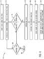
- FIG. 4 illustrates a flow chart of a method 70 of using the mobile computing device 22 of FIG. 3 for automatically accessing and communicating data collected by the RTU 18 to the cloud-based computing system 12 of FIG. 1 .
- the method 70 may be performed in any suitable order.
- the method 70 is described as being performed by the mobile computing device 22, it should be understood that the method 70 may be performed by any suitable computing device.
- the mobile computing device 22 may scan a local area for the RTUs 18.
- the mobile computing device 22 may scan for Bluetooth, IR, or RF signals broadcasted by the RTUs 18.
- the signals broadcast by the RTUs 18 may include identification data regarding the RTUs 18 and/or indications of presence of the RTUs 18.
- the mobile computing device 22 may continuously scan the local area scan the local area at regular or irregular intervals, while the mobile computing device 22 is powered on, regardless of the application being executed on the mobile computing device 22.
- the mobile computing device 22 may establish communication to RTUs 18 detected during the scan. It should be noted that the communication to the identified RTUs 18 may be established automatically when the mobile computing device 22 is within an effective range of short-range wireless communication (e.g., Bluetooth®, IR communication, radio frequency (RF) communication, and the like). As such, the RTUs 18 may regularly send an identification message to be detected by the scanning mobile computing device 22. In certain embodiments, after identifying the RTUs 18, the mobile computing device 22 may send an acknowledge message to the RTUs 18 indicating that the mobile computing device 22 has recognized the presence of the RTUs 18. Alternatively, the mobile computing device 22 may send identification messages that may be detected by the RTUs 18, which may then send acknowledgement signals to the mobile computing device 22.
- short-range wireless communication e.g., Bluetooth®, IR communication, radio frequency (RF) communication, and the like.
- RF radio frequency
- the mobile computing device 22 may receive a signal or an indication from each of the connected RTUs 18 indicating whether new data is available for download. For example, the signal or indication may indicate whether there is new data acquired by the RTUs 18 since the last data downloading to the respective mobile computing device 22.
- the mobile computing device 22 may provide an indication of the data previously acquired from the respective RTU 18 and uploaded to the cloud-based computing system 12. The RTU 18 may then remove a tag or alter the metadata of the previously transmitted data to indicate that the data was successfully uploaded.
- the mobile computing device 22 may download the new data.
- the mobile computing device 22 may perform preliminary analyses based on the downloaded data. As set forth above, the mobile computing device 22 may determine whether the data downloaded from the RTU 18 are within an expected range of values. Examples of data may include any data acquired by the RTU 18, such as extracted hydrocarbon flow rates, temperatures and amounts of hydrocarbons being processed or extracted by components in the hydrocarbon site 30, tubing head pressure, tubing head temperature, case head pressure, flowline pressure, wellhead pressure, wellhead temperature, well depth, tubing length, tubing size, choke size, reservoir pressure, bottom hole temperature, well test data, fluid properties of the hydrocarbons being extracted, and the like.
- the preliminary analyses may not involve intensive computing power or significant computational time.
- the preliminary analyses may be performed on the limited computing power available via the mobile computing device 22, as compared to the computing power available via the cloud-based computing system 12.
- the results of the preliminary analyses may be saved in the memory 54 or the storage 56 of the mobile computing device 22.
- the mobile computing device 22 may send an alert or indication in response to determining that the downloaded data are outside the respective expected range of values.
- an audio or visual alert may be presented via the display 60 of the mobile computing device 22.
- the audio or visual alert may include information showing a comparison between the downloaded values and the expected range of values.
- the user of the mobile computing device 22 may have knowledge of preliminary assessment with respect to certain aspects relating to operation of the hydrocarbon site 30.
- the mobile computing device 22 may send a command to the RTU 18 to adjust the operations of a respective machine based on the alert.
- the mobile computing device 22 may send a command to the respective RTU 18 to cease the operation of the respective machine.
- the mobile computing device 22 may upload the data to the cloud-based computing system 12 when suitable communication (e.g., Internet) is available. As such, the mobile computing device 22 may scan the area at regular or irregular intervals for a communication link to the cloud-based computing system 12. After the mobile computing device 22 detects the communication link to the cloud-based computing system 12, the mobile computing device 22 may send the downloaded data to the cloud-based computing system 12.
- the data may include the downloaded data from the RTU 18, as well as results of the preliminary analyses.
- the method 70 may proceed to block 86 where the mobile computing device 22 may determine whether there is another identified RTU 18 within the proximity. If so (e.g., another RTU 18 identified), the mobile computing device 22 may return to block 74 and proceed through block 84. If not (e.g., no other RTU 18 identified), the mobile computing device 22 may end the method 70 at block 88. As such, the communication architecture 10 may reduce the redundancy of downloading and/or analyzing data that has already been downloaded and/or analyzed.
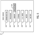
- FIG. 5 illustrates a block diagram of the drone device 24 that may be employed in the communication architecture 10 of FIG. 1 .
- the drone device 24 may include a communication component 100, a processor 102, a memory 104, a storage 106, input/output (I/O) ports 108, a motor 110, and a battery 112.
- the communication component 100, the processor 102, the memory 104, the storage 106, the I/O ports 108, and application 114 may correspond to the descriptions provided above with respect to similar components of the mobile computing device 22 of FIG. 3 .
- the motor 110 may be any suitable drone motor or engine that enables aerial movements of the drone device 24.
- the battery 112 may be any suitable rechargeable and/or non-rechargeable battery or power storage device that is capable of powering operation of the drone device 24 (e.g., providing power for various components of the drone device 24).
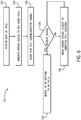
- FIG. 6 illustrates a flow chart of a method 120 of using the drone device 24 of FIG. 5 for automatically accessing and communicating data collected by the RTU 18 to the cloud-based computing system 12 of FIG. 1 .
- the method 120 may be performed in any suitable order.
- the method 120 is described as being performed by the drone device 24, it should be understood that the method 120 may be performed by any suitable computing device that is capable of adjusting its position.
- the drone device 24 may receive a map or mapping information (e.g., global positioning system (GPS) coordinate) of the RTUs 18.
- the drone device 24 may receive the map via wired or wireless communication, and the map may be stored in in the memory 104 or the storage 106 of the drone device 24.
- the map may also include GPS coordinates of the cloud gateways 26 and/or other components of the hydrocarbon site 30.
- transmitting of the map to the drone device 24 may be controlled via a controller (including a processor and memory) at the hydrocarbon site 30.
- the drone device 24 may fly over the RTUs 18 identified in the map. For example, after receiving the map of RTUs 18, the drone device 24 fly to the locations associated with RTUs 18.
- the drone device 24 may scan for communication signals from the respective RTU 18. For example, as the drone device 24 flies approaches the location of a respective RTU 18, the drone device 24 may scan a local area for Bluetooth, IR, RF, or near-field signals broadcast by the respective RTU 18.
- the drone device 24 may determine whether communication signals from the RTUs 18 were received. If the communication signals were received, the drone device 24 may proceed to block 132. At block 134, the drone device 24 may perform the operations of block 74 in the method 70 as discussed above in FIG. 4 . However, if the drone device 24 does not receive any communication signal from the respective RTU 18 at block 128, the drone device 24 may move closer to an expected location of the respective RTU 18 as identified on the map (block 130). For example, the drone device 24 may not receive communication signals from the RTUs 18 because the drone device 24 is too high or too far away from the physical RTUs 18. Thus, the drone device 24 may change its route and/or position to get closer to or decrease the distance between itself and the respective RTU 18. After adjusting its position at block 130, the drone device 24 may return to block 128 and scan again for a communication signal from the respective RTU 18. As such, the drone device 24 may continue to adjust its position until a communication signal from the respective RTU 18 is received.
- the drone device 24 may proceed to block 132.
- the drone device 24 may perform the operations described in blocks 74-84 of the method 70 described above. That is, the drone device 24 may download data from the respective RTU 18, perform preliminary analyses as discussed above, and upload data to the cloud-based computing system 12 in response to a communication link to the cloud-based computing system 12 being established. It should be noted that, in some embodiment, the drone device 24 may transmit the alert or indication (block 82) to a suitable computing device within the hydrocarbon site 30 to notify an operator in addition to or in lieu of providing an indication of the alert on a display of the drone device 24.
- the alert or indication may be transmitted to a local device capable of receiving the alert or indication from the drone device 24 via a local (e.g., within the hydrocarbon site 30) wireless short- range communication network (e.g., Bluetooth®, infrared (IR) communication, radio frequency (RF) communication, and the like).
- a local wireless short-range communication network e.g., Bluetooth®, infrared (IR) communication, radio frequency (RF) communication, and the like.
- the drone device 24 in response to determining that the downloaded data are outside the respective expected range of values, the drone device 24 may navigate to (e.g., based on the map of the hydrocarbon site 30) to the local device to transmit the alert to the local device before flying to the next identified RTU 18 (e.g., block 124).
- the local device may present the alert to users or personnel via suitable display, audio output, or the like.
- the local device may perform some corrective action (e.g., power down device).
- the local device may communicate the alert to a user device (e.g., mobile phone, smartphone, tablet, laptop computer) via the wireless short-range communication network.
- a user device e.g., mobile phone, smartphone, tablet, laptop computer
- such local device may be a local computer or a data processing facility located within a particular range with respect to the RTUs 18, within a range of a communication network accessible by the RTUs 18, or the gateway device of the cloud gateways 26.
Landscapes
- Engineering & Computer Science (AREA)
- Physics & Mathematics (AREA)
- Life Sciences & Earth Sciences (AREA)
- Mining & Mineral Resources (AREA)
- Geology (AREA)
- General Physics & Mathematics (AREA)
- Environmental & Geological Engineering (AREA)
- Geochemistry & Mineralogy (AREA)
- General Life Sciences & Earth Sciences (AREA)
- Fluid Mechanics (AREA)
- Computer Networks & Wireless Communication (AREA)
- Signal Processing (AREA)
- Aviation & Aerospace Engineering (AREA)
- Astronomy & Astrophysics (AREA)
- Geophysics (AREA)
- Emergency Management (AREA)
- Business, Economics & Management (AREA)
- Selective Calling Equipment (AREA)
- Arrangements For Transmission Of Measured Signals (AREA)
Abstract
Description
- The present disclosure relates generally to improved monitoring of operations at a hydrocarbon well site. More specifically, the present disclosure relates to acquiring data from a remote hydrocarbon well site.
- As hydrocarbons are extracted from hydrocarbon reservoirs via hydrocarbon wells in oil and/or gas fields, the extracted hydrocarbons may be transported to various types of equipment, tanks, and the like via a network of pipelines. For example, the hydrocarbons may be extracted from the reservoirs via the hydrocarbon wells and may then be transported, via the network of pipelines, from the wells to various processing stations that may perform various phases of hydrocarbon processing to make the produced hydrocarbons available for use or transport.
- Information related to the extracted hydrocarbons or related to the equipment extracting, transporting, storing, or processing the extracted hydrocarbons may be gathered at the well site or at various locations along the network of pipelines. This information or data may be used to ensure that the well site or pipelines are operating safely and that the extracted hydrocarbons have certain desired qualities (e.g., flow rate, temperature). However, given the remote locations in which hydrocarbon well sites are located, it may be challenging to access or communicate these information or data to a centralized system or location to be processed and/or analyzed. Accordingly, it is now recognized that improved systems and methods for accessing data from remote sites, such as a hydrocarbon well site, are desirable.
- In one embodiment, a system includes a cloud-based computing system communicatively coupled to a first communication network. The system includes one or more remote terminal units (RTUs) configured to control operations of one or more well devices associated with a hydrocarbon well, wherein the one or more RTUs are inaccessible to the first communication network. The system also includes a mobile computing device configured to communicatively couple to the one or more RTUs via a second communication network in response to the mobile computing device being within a coverage range of the second communication network. The mobile computing device is also configured to download data from the one or more RTUs via the second communication network, communicatively couple to the cloud-based computing system in response to detecting access to the first communication network, and transmit the data to the cloud-based computing system via the first communication network.
- In another embodiment, a method includes communicatively coupling, via a processor, to one or more remote terminal units (RTUs) in response to the processor being within a distance to the one or more RTUs, wherein the one or more RTUs are configured to control operations of one or more well devices associated with a hydrocarbon well. The method includes downloading, via the processor, data from the one or more RTUs via a first communication network. The method includes communicatively coupling, via the processor, to a cloud-based computing system in response to detecting access to a second communication network, wherein the one or more RTUs are inaccessible to the second communication network. The method also includes transmitting, via the processor, the data to the cloud-based computing system via the second communication network.
- In yet another embodiment, a drone device includes a motor and a processor. The processor is configured to receive mapping information comprising one or more locations of one or more remote terminal units (RTUs), wherein the one or more RTUs are configured to control operations of one or more well devices associated with a hydrocarbon well. The processor is configured to cause the motor to operate such that the drone device flies to the one or more locations of the one or more RTUs. The processor is configured to communicatively couple to the one or more RTUs in response to the drone device being within a coverage range of a first communication network. The processor is configured to download data from the one or more RTUs via the first communication network. The processor is configured to communicatively couple to a cloud-based computing system in response to detecting access to a second communication network, wherein the one or more RTUs are inaccessible to the second communication network. The processor is also configured to transmit the data to the cloud-based computing system via the second communication network.
- These and other features, aspects, and advantages of the present embodiment disclosed herein will become better understood when the following detailed description is read with reference to the accompanying drawings in which like characters represent like parts throughout the drawings, wherein:
-
FIG. 1 illustrates an overview of a communication architecture of an industrial enterprise that leverages a cloud-based computing system, in accordance with embodiments presented herein; -
FIG. 2 illustrates a schematic diagram of an example hydrocarbon site that may produce and process hydrocarbons, in accordance with embodiments presented herein; -
FIG. 3 illustrates a block diagram of a mobile computing device that may be employed in the communication architecture ofFIG. 1 , in accordance with embodiments presented herein; -
FIG. 4 illustrates a flow chart of a method of using the mobile computing device ofFIG. 3 for automatically accessing and communicating data from a remote terminal unit (RTU) to the cloud-based computing system ofFIG. 1 , in accordance with embodiments presented herein; -
FIG. 5 illustrates a block diagram of a drone device that may be employed in the communication architecture ofFIG. 1 , in accordance with embodiments presented herein; and -
FIG. 6 illustrates a flow chart of a method of using the drone device ofFIG. 5 for automatically accessing and communicating data from a remote terminal unit (RTU) to the cloud-based computing system ofFIG. 1 , in accordance with embodiments presented herein. - One or more specific embodiments will be described below. In an effort to provide a concise description of these embodiments, not all features of an actual implementation are described in the specification. It should be appreciated that in the development of any such actual implementation, as in any engineering or design project, numerous implementation-specific decisions must be made to achieve the developers' specific goals, such as compliance with system-related and business-related constraints, which may vary from one implementation to another. Moreover, it should be appreciated that such a development effort might be complex and time consuming, but would nevertheless be a routine undertaking of design, fabrication, and manufacture for those of ordinary skill having the benefit of this disclosure.
- When introducing elements of various embodiments disclosed herein, the articles "a," "an," "the," and "said" are intended to mean that there are one or more of the elements. The terms "comprising," "including," and "having" are intended to be inclusive and mean that there may be additional elements other than the listed elements.
- Embodiments of the present disclosure are generally directed towards improved systems and methods for accessing data collected at a remote site, such as a hydrocarbon well site. Moreover, embodiments of the present disclosure are related to improving communication architecture to communicate data from a remote site to a cloud-based computing system.
- Generally, a hydrocarbon well site may include a monitoring system that may be placed at various locations at the hydrocarbon site to monitor information or data related to certain aspects of the hydrocarbon well site. For example, the hydrocarbon well site may include one or more remote terminal units (RTUs) that may monitor and store information or data related to operation of the hydrocarbon well site. The monitored information or data may be processed and/or analyzed to provide valuable insights with respect to various aspects of the hydrocarbon well site. If the hydrocarbon well site is located where suitable communication network (e.g., Internet) is available, the monitored information or data may be transmitted to a cloud-based computing system having relatively higher computation power as compared to the RTUs to process and/or analyze the information or data. However, given a hydrocarbon well site is often at a remote location, where a suitable communication network is not available, accessing to the monitored information or data may be difficult or costly (e.g., unrealistic or economically not viable to establish a suitable communication network for a remote location). Nonetheless, the monitored information or data may be of value to the enterprise operating the hydrocarbon well site. Accordingly, it is now recognized that improved systems and methods for accessing data from a remote site, such as a hydrocarbon well site, are desirable.
- In particular, in the absence of a long-range wireless communication network connected to a cloud-based computing system, mobile computing devices (e.g., mobile phones, smartphones, tablets, laptop computers) may be utilized to download data from RTUs via short-range wireless communication techniques and perform preliminary analyses based on the downloaded data. Subsequently, when the mobile computing devices are brought back to locations where suitable communication to the cloud-based computing system is available, the mobile computing devices may transmit the downloaded data and/or results of the preliminary analyses to the cloud-based computing system. In some embodiments, the mobile computing devices may generate an alert or send instructions for assets at the hydrocarbon site to implement based on the preliminary analyses performed by the mobile computing devices.
- Alternatively or additionally, drone devices or the like may be utilized to perform similar functions as the mobile computing devices set forth above. In particular, the drone devices may be automated to fly to various RTUs to download data and/or perform preliminary analyses. As such, in the absence of a long-range wireless communication network (e.g., Internet), the mobile computing devices and/or drone devices capable of downloading data via short-range wireless communication techniques (e.g., Bluetooth®, infrared (IR) communication, radio frequency (RF) communication, and the like) may bridge the connection between the RTUs and the cloud-based computing system. It should be noted that while an RTU is used as an example, the systems and methods discussed herein may be used to download data from any suitable appliances (e.g., devices having controllers) capable of storing data and communicating data via short-range wireless communication techniques.
- By way of introduction,
FIG. 1 illustrates a high-level overview ofcommunication architecture 10 of anindustrial enterprise 11 that leverages a cloud-basedcomputing system 12 to improve operations of various industrial devices. Theenterprise 11 may include one or moreindustrial facilities 14, each having a number ofindustrial devices 16 in use. Theindustrial devices 16 may make up one or more automation systems operating within therespective facilities 14. Exemplary automation systems may include, but are not limited to, batch control systems (e.g., mixing systems), continuous control systems (e.g., proportional-integral-derivative (PID) control systems), or discrete control systems. Although theindustrial enterprise 11 ofFIG. 1 is described with respect to automation systems, it should be noted that theindustrial enterprise 11 described herein may be applied to other industrial environments, such as hydrocarbon production well sites, as will be detailed below. -
Industrial devices 16 may include devices, such as industrial controllers (e.g., programmable logic controllers or other types of programmable automation controllers), field devices such as sensors and meters, motor drives, operator interfaces (e.g., human-machine interfaces, industrial monitors, graphic terminals, message displays, etc.), industrial robots, barcode markers and readers, vision system devices (e.g., vision cameras), smart welders, or other such industrial devices. Theindustrial devices 16 may also be part of a mobile control application, such as a system contained in a skid, a truck, or other service vehicle. Information or data related to various aspects of theindustrial devices 16 may be monitored via a monitoring system. The monitoring system may be a controller, a remote terminal unit (RTU), or any computing device that may include communication abilities, processing abilities, and the like. For discussion purposes, the monitoring system will be embodied asRTUs 18 throughout the present disclosure. However, it should be understood that theRTU 18 may be any suitable component capable of monitoring and/or controlling various components of theindustrial devices 16. There may be wired communication or wireless short-range communication (e.g., Bluetooth®, infrared (IR) communication, radio frequency (RF) communication, and the like) to enable communication (e.g., data transmission) of theindustrial devices 16 and theRTUs 18. - In certain embodiments, the cloud-based
computing system 12 may be a public cloud accessible via the Internet by devices having Internet connectivity and appropriate authorizations to utilize cloud-based services. In some scenarios, the cloud-basedcomputing system 12 may be a platform-as-a-service (PaaS), and the cloud-based services may reside and execute on the cloud-basedcomputing system 12. In certain instances, access to cloud-basedcomputing system 12 may be provided to users as a subscription service by an owner of the respective cloud-based services. Alternatively, the cloud-basedcomputing system 12 may be a private network of computers operated internally by theindustrial enterprise 11. For example, the cloud-basedcomputing system 12 may involve a set of servers hosting the cloud-based services and residing on an internal network protected by a firewall. The cloud-based services may include, but are not limited to, data storage, data analysis, control applications, visualization applications such as the cloud-based operator interface system, reporting applications, Enterprise Resource Planning (ERP) applications, notification services, or other such applications. In certain embodiments, the cloud-basedcomputing system 12 may also be communicatively coupled to adatabase 20 that may store data. The cloud-basedcomputing system 12 may use the data stored within thedatabase 20 to perform various types of data analyses. - Generally, the cloud-based
computing system 12 may be dedicated to performing various types of complex and time-consuming analysis that may include analyzing a large amount of data. As such, in some embodiments, theindustrial enterprise 11 may leverage the computing power of the cloud-basedcomputing system 12 to analyze data acquired from a number ofRTUs 18, perform more comprehensive data analyses more efficiently, and/or provide users or personnel with accesses to additional information and operational support to more efficiently manage the operations of theindustrial enterprise 11. As set forth above, theindustrial enterprise 11, such as a hydrocarbon production well site, may be at a remote location where no suitable communication network is available for transmitting data from theindustrial enterprise 11 to the cloud-basedcomputing system 12. In the absence of a suitable communication network (e.g., Internet), thecommunication architecture 10 may use one or more mobile computing devices 22 (e.g., mobile phones, smartphones, tablets, laptop computers) and/or one ormore drone devices 24 or the like to download data from theRTUs 18, and subsequently transmit the downloaded data to the cloud-basedcomputing system 12 when suitable communication network (e.g., Internet) becomes available. - As an example, in the absence of a network connection, data collected by the
RTU 18 may be stored in theRTU 18 until a user carrying themobile computing device 22 travels near theRTU 18. After themobile computing device 22 is within an effective distance where short-range wireless communication is available (e.g., Bluetooth®, IR communication, radio frequency (RF) communication, local wireless network, or the like), themobile computing device 22 may download the data stored on theRTU 18 and store the downloaded data in themobile computing device 22. Subsequently, themobile computing device 22 may transmit the downloaded data to the cloud-basedcomputing system 12 after themobile computing device 22 is brought to a location where a network connection (e.g., accessible to cloud-based computing system 12) is available. In certain embodiments, themobile computing device 22 can download and store data frommultiple RTUs 18 and transmit the downloaded data to the cloud-basedcomputing system 12 when a communication link to the cloud-basedcomputing system 12 is established. As another example, in the absence of a network connectedRTU 18, thedrone device 24 may fly to one or more RTUs 18 to download data and subsequently fly to a location where network connection is available and transmit the downloaded data to the cloud-basedcomputing system 12. In this manner, by utilizing the one or moremobile computing devices 22 and/or the one ormore drone devices 24 as part of thecommunication architecture 10, even in the absence of network connection, thecommunication architecture 10 may transfer data stored on theRTUs 18 to the cloud-basedcomputing system 12. - In certain embodiments, the
communication architecture 10 may includeseparate cloud gateways 26 at the respectiveindustrial facilities 14 to provide communication to the cloud-basedcomputing system 12. For example, thecloud gateways 26 may serve as intermediaries in a communication link between themobile computing devices 22 or the one ormore drone devices 24 and the cloud-basedcomputing system 12. In this case, the one or moremobile computing devices 22 and/or the one ormore drone devices 24 may upload the downloaded data to the cloud-basedcomputing system 12 via thecloud gateways 26. - As mentioned above, the cloud-based
computing system 12 may also be implemented in other industrial environments such as a hydrocarbon well site, and the like. Keeping this in mind,FIG. 2 illustrates a schematic diagram of anexample hydrocarbon site 30 that may employ the cloud-basedcomputing system 12 to assist in the operation and maintenance of various well devices at thehydrocarbon site 30. In the illustrated embodiment, thehydrocarbon site 30 may be an area in which hydrocarbons, such as crude oil and natural gas, may be extracted from the ground, processed, and stored. As such, thehydrocarbon site 30 may include a number of wells and a number of well devices that may control the flow of hydrocarbons being extracted from the wells. In one embodiment, the well devices at thehydrocarbon site 30 may include any device equipped to monitor and/or control production of hydrocarbons at a well site. As such, the well devices may includepumpjacks 32, submersible pumps 34, welltrees 36, and the like. After the hydrocarbons are extracted from the surface via the well devices, the extracted hydrocarbons may be distributed to other devices such aswellhead distribution manifolds 38,separators 40,storage tanks 42, and the like. At thehydrocarbon site 30, thepumpjacks 32, submersible pumps 34, welltrees 36,wellhead distribution manifolds 38,separators 40, andstorage tanks 42 may be connected together via a network ofpipelines 44. As such, hydrocarbons extracted from a reservoir may be transported to various locations at thehydrocarbon site 30 via the network ofpipelines 44. - The
pumpjack 32 may mechanically lift hydrocarbons (e.g., oil) out of a well when a bottom hole pressure of the well is not sufficient to extract the hydrocarbons to the surface. Thesubmersible pump 34 may be an assembly that may be submerged in a hydrocarbon liquid that may be pumped. As such, thesubmersible pump 34 may include a hermetically sealed motor, such that liquids may not penetrate the seal into the motor. Further, the hermetically sealed motor may push hydrocarbons from underground areas or the reservoir to the surface. - The
well trees 36 or Christmas trees may be an assembly of valves, spools, and fittings used for natural flowing wells. As such, thewell trees 36 may be used for an oil well, gas well, water injection well, water disposal well, gas injection well, condensate well, and the like. Thewellhead distribution manifolds 38 may collect the hydrocarbons that may have been extracted by thepumpjacks 32, the submersible pumps 34, and thewell trees 36, such that the collected hydrocarbons may be routed to various hydrocarbon processing or storage areas in thehydrocarbon site 30. - The
separator 40 may include a pressure vessel that may separate well fluids produced from oil and gas wells into separate gas and liquid components. For example, theseparator 40 may separate hydrocarbons extracted by thepumpjacks 32, the submersible pumps 34, or thewell trees 36 into oil components, gas components, and water components. After the hydrocarbons have been separated, each separated component may be stored in aparticular storage tank 42. The hydrocarbons stored in thestorage tanks 42 may be transported via thepipelines 44 to transport vehicles, refineries, and the like. - The well devices may also include monitoring systems that may be placed at various locations in the
hydrocarbon site 30 to monitor or provide information related to certain aspects of thehydrocarbon site 30. The monitoring system may be a controller, a remote terminal unit (RTU), or any computing device that may include communication abilities, processing abilities, and the like. As set forth above, for discussion purposes, the monitoring system is embodied as theRTU 18 throughout the present disclosure. However, it should be understood that theRTU 18 may be any component capable of monitoring and/or controlling various components at thehydrocarbon site 30. - The
RTU 18 may include sensors or may be coupled to various sensors that may monitor various properties associated with a component at the hydrocarbon site. TheRTU 18 may then analyze the various properties associated with the component and may control various operational parameters of the component. For example, theRTU 18 may measure a pressure or a differential pressure of a well or a component (e.g., storage tank 42) in thehydrocarbon site 30. TheRTU 18 may also measure a temperature of contents stored inside a component in thehydrocarbon site 30, an amount of hydrocarbons being processed or extracted by components in thehydrocarbon site 30, and the like. TheRTU 18 may also measure a level or amount of hydrocarbons stored in a component, such as thestorage tank 42. In certain embodiments, theRTU 18 may be iSens-GP Pressure Transmitter, iSens-DP Differential Pressure Transmitter, iSens-MV Multivariable Transmitter, iSens-T2 Temperature Transmitter, iSens-L Level Transmitter, or Isens-IO Flexible I/O Transmitter manufactured by Rockwell Automation®. - In one embodiment, the
RTU 18 may include a sensor that may measure pressure, temperature, fill level, flow rates, and the like. TheRTU 18 may also include a transmitter, such as a radio wave transmitter, that may transmit data acquired by the sensor via an antenna or the like. The sensor in theRTU 18 may be wireless sensors that may be capable of receive and sending data signals betweenRTUs 18. To power the sensors and the transmitters, theRTU 18 may include a battery or may be coupled to a continuous power supply. Since theRTU 18 may be installed in harsh outdoor and/or explosion-hazardous environments, theRTU 18 may be enclosed in an explosion-proof container that may meet certain standards established by the National Electrical Manufacturer Association (NEMA) and the like, such as a NEMA 4X container, a NEMA 7X container, and the like. - The
RTU 18 may transmit data acquired by the sensor or data processed by a processor to other monitoring systems, a router device, a supervisory control and data acquisition (SCADA) device, or the like. As such, theRTU 18 may enable users to monitor various properties of various components in thehydrocarbon site 30 without being physically located near the corresponding components. - In operation, the
RTU 18 may receive real-time or near real-time data associated with a well device. The data may include, for example, tubing head pressure, tubing head temperature, case head pressure, flowline pressure, wellhead pressure, wellhead temperature, and the like. In any case, theRTU 18 may analyze the real-time data with respect to static data that may be stored in a memory of theRTU 18. The static data may include a well depth, a tubing length, a tubing size, a choke size, a reservoir pressure, a bottom hole temperature, well test data, fluid properties of the hydrocarbons being extracted, and the like. TheRTU 18 may also analyze the real-time data with respect to other data acquired by various types of instruments (e.g., water cut meter, multiphase meter) to determine an inflow performance relationship (IPR) curve, a desired operating point for the wellhead, key performance indicators (KPIs) associated with the wellhead, wellhead performance summary reports, and the like. - Although the
RTU 18 may be capable of performing the above-referenced analyses, theRTU 18 may not be capable of performing the analyses in a timely manner. Moreover, by just relying on the processor capabilities of theRTU 18, theRTU 18 is limited in the amount and types of analyses that it may perform. Moreover, since theRTU 18 may be limited in size, the data storage abilities may also be limited. Keeping the foregoing in mind, in certain embodiments, the information or data stored in theRTU 18 may be transmitted (e.g., via themobile computing device 22 and/or the drone device 24) to the cloud-basedcomputing system 12. That is in cases that connection to a suitable communication (e.g., Internet) is not available, the information or data stored in theRTU 18 may be transmitted to the cloud-basedcomputing system 12 using themobile computing device 22 and/or thedrone device 24 as intermediary data carrier. The cloud-basedcomputing system 12 may use its larger processing capabilities to analyze data acquired bymultiple RTUs 18. In certain embodiments, themobile computing device 22 and/or thedrone device 24 may also perform preliminary analyses based on the data collected by theRTU 18. The results of the preliminary analyses may also be transmitted to the cloud-basedcomputing system 12. -
FIG. 3 illustrates a block diagram of themobile computing device 22 that may be employed in thecommunication architecture 10 ofFIG. 1 . In the illustrated embodiment, themobile computing device 22 may include a communication component 50, aprocessor 52, amemory 54, astorage 56, input/output (I/O)ports 58, a display 60, and the like. The communication component 50 may be a wireless or wired communication component that may facilitate communication withdifferent RTUs 18, gateway communication devices of thecloud gateways 26, the cloud-basedcomputing system 12, the various control systems, and the like. Theprocessor 52 may be any type of computer processor or microprocessor capable of executing computer-executable code. Thememory 54 and thestorage 56 may be any suitable articles of manufacture that can serve as media to store processor-executable code, data, or the like. These articles of manufacture may represent computer-readable media (i.e., any suitable form of memory or storage) that may store the processor-executable code used by theprocessor 52 to perform the presently disclosed techniques. - The
memory 54 or thestorage 56 may be used to store data downloaded from the one ormore RTUs 18. Thememory 54 and thestorage 56 may be used to store data received via the I/O ports 58, data analyzed by theprocessor 52, or the like. Thememory 54 and thestorage 56 may be used to store data related to theRTU 18. Examples of the data related to theRTU 18 may include an indication of an identity of theRTU 18, a location (e.g., global positioning system (GPS) coordinate) of theRTU 18, a context or relationship of theRTU 18 within thecommunication architecture 10, a vendor associated with theRTU 18, a model number associated with theRTU 18, a serial number associated with theRTU 18, a firmware version associated with theRTU 18, a well device software application associated with theRTU 18, and the like. Thememory 54 and thestorage 56 may be used to store data providing details regarding the well site associated with theRTU 18. That is, the data may indicate a location (e.g., GPS coordinates) associated with the well site, a type of well site that is being monitored and/or controlled. For instance, the well site may be a land oil site, a subsea oil site, a gas site, a shale gas site, or the like. - The
memory 54 or thestorage 56 may also be used to store anapplication 62, a firmware, an application portability profile (APP), or the like. Theapplication 62 may run in the background or upon execution by a user. Theapplication 62 when executed by theprocessor 52 may enable themobile computing device 22 to function as intermediary data carrier in thecommunication architecture 10. That is, theapplication 62 may enable themobile computing device 22 to connect to and download data from theRTU 18 when themobile computing device 22 is within an effective distance of wireless short-range communication (e.g., Bluetooth®, infrared (IR) communication, radio frequency (RF) communication, and the like) with therespective RTU 18. Subsequently, theapplication 62 may enable themobile computing device 22 to connect to and upload data to thecloud gateways 26 or the cloud-basedcomputing system 12 when suitable communication (e.g., Internet) is available. Theapplication 62, when executed by theprocessor 52, may also enable themobile computing device 22 to perform preliminary analyses based on the data downloaded from theRTU 18. The preliminary analyses may include determining whether the data downloaded from theRTU 18 are within an expected range of values. Examples of data may include extracted hydrocarbon flow rates, temperatures and amounts of hydrocarbons being processed or extracted by components in thehydrocarbon site 30, tubing head pressure, tubing head temperature, case head pressure, flowline pressure, wellhead pressure, wellhead temperature, well depth, tubing length, tubing size, choke size, reservoir pressure, bottom hole temperature, well test data, fluid properties of the hydrocarbons being extracted, and the like. Theapplication 62, when executed by theprocessor 52, may also enable themobile computing device 22 to provide an alert or indication when the downloaded data are outside an expected range of values. It should be noted that the alert or indication may be provided in any suitable manner (e.g., visual or audio alerts). In some embodiments, the alert may cause theapplication 62 to alter the appearance of the display 60, the operation of themobile computing device 22, or the like, such that the user of themobile computing device 22 is aware of the alert even when themobile computing device 22 is in a sleep or power-savings mode. That is, themobile computing device 22 may receive the alert, which may cause themobile computing device 22 to exit a current mode of operation (e.g., sleep) to provide an indication to the user of the alert. - The I/
O ports 58 may be interfaces between themobile computing device 22 and other types of equipment, computing computing devices, or peripheral devices. The display 60 may include any type of electronic display such as a liquid crystal display, a light-emitting-diode display, and any type of audio transducer such as a speaker. In certain embodiments, the display 60 may be a touch screen display or any other type of display capable of receiving inputs from the user of themobile computing device 22. In certain embodiments, results of the preliminary analyses and/or the alert or indication (e.g., provided when the downloaded data are outside an expected range of values) may be presented using the display 60. -
FIG. 4 illustrates a flow chart of amethod 70 of using themobile computing device 22 ofFIG. 3 for automatically accessing and communicating data collected by theRTU 18 to the cloud-basedcomputing system 12 ofFIG. 1 . Although the following description of themethod 70 is provided in a particular order, it should be noted that themethod 70 may be performed in any suitable order. In addition, although themethod 70 is described as being performed by themobile computing device 22, it should be understood that themethod 70 may be performed by any suitable computing device. - Referring now to
FIG. 4 , atblock 72, themobile computing device 22 may scan a local area for theRTUs 18. For example, themobile computing device 22 may scan for Bluetooth, IR, or RF signals broadcasted by theRTUs 18. The signals broadcast by theRTUs 18 may include identification data regarding theRTUs 18 and/or indications of presence of theRTUs 18. In certain embodiments, themobile computing device 22 may continuously scan the local area scan the local area at regular or irregular intervals, while themobile computing device 22 is powered on, regardless of the application being executed on themobile computing device 22. - At
block 74, themobile computing device 22 may establish communication toRTUs 18 detected during the scan. It should be noted that the communication to the identifiedRTUs 18 may be established automatically when themobile computing device 22 is within an effective range of short-range wireless communication (e.g., Bluetooth®, IR communication, radio frequency (RF) communication, and the like). As such, theRTUs 18 may regularly send an identification message to be detected by the scanningmobile computing device 22. In certain embodiments, after identifying theRTUs 18, themobile computing device 22 may send an acknowledge message to theRTUs 18 indicating that themobile computing device 22 has recognized the presence of theRTUs 18. Alternatively, themobile computing device 22 may send identification messages that may be detected by theRTUs 18, which may then send acknowledgement signals to themobile computing device 22. - After the
mobile computing device 22 establishes a communication link to the identifiedRTUs 18, atblock 76, themobile computing device 22 may receive a signal or an indication from each of the connectedRTUs 18 indicating whether new data is available for download. For example, the signal or indication may indicate whether there is new data acquired by theRTUs 18 since the last data downloading to the respectivemobile computing device 22. In some embodiments, after establishing the communication link, themobile computing device 22 may provide an indication of the data previously acquired from therespective RTU 18 and uploaded to the cloud-basedcomputing system 12. TheRTU 18 may then remove a tag or alter the metadata of the previously transmitted data to indicate that the data was successfully uploaded. - Upon receiving the indication that there is new data available for download, at
block 78, themobile computing device 22 may download the new data. Atblock 80, themobile computing device 22 may perform preliminary analyses based on the downloaded data. As set forth above, themobile computing device 22 may determine whether the data downloaded from theRTU 18 are within an expected range of values. Examples of data may include any data acquired by theRTU 18, such as extracted hydrocarbon flow rates, temperatures and amounts of hydrocarbons being processed or extracted by components in thehydrocarbon site 30, tubing head pressure, tubing head temperature, case head pressure, flowline pressure, wellhead pressure, wellhead temperature, well depth, tubing length, tubing size, choke size, reservoir pressure, bottom hole temperature, well test data, fluid properties of the hydrocarbons being extracted, and the like. It should be noted that the preliminary analyses may not involve intensive computing power or significant computational time. In other words, the preliminary analyses may be performed on the limited computing power available via themobile computing device 22, as compared to the computing power available via the cloud-basedcomputing system 12. The results of the preliminary analyses may be saved in thememory 54 or thestorage 56 of themobile computing device 22. - At
block 82, themobile computing device 22 may send an alert or indication in response to determining that the downloaded data are outside the respective expected range of values. For example, an audio or visual alert may be presented via the display 60 of themobile computing device 22. The audio or visual alert may include information showing a comparison between the downloaded values and the expected range of values. As such, the user of themobile computing device 22 may have knowledge of preliminary assessment with respect to certain aspects relating to operation of thehydrocarbon site 30. In some embodiments, after the alert is generated, themobile computing device 22 may send a command to theRTU 18 to adjust the operations of a respective machine based on the alert. By way of example, if the alert indicates that a detected temperature is above a threshold, themobile computing device 22 may send a command to therespective RTU 18 to cease the operation of the respective machine. - At
block 84, themobile computing device 22 may upload the data to the cloud-basedcomputing system 12 when suitable communication (e.g., Internet) is available. As such, themobile computing device 22 may scan the area at regular or irregular intervals for a communication link to the cloud-basedcomputing system 12. After themobile computing device 22 detects the communication link to the cloud-basedcomputing system 12, themobile computing device 22 may send the downloaded data to the cloud-basedcomputing system 12. The data may include the downloaded data from theRTU 18, as well as results of the preliminary analyses. - Referring back to block 76, if the signal or indication indicates that there is no new data available, the
method 70 may proceed to block 86 where themobile computing device 22 may determine whether there is another identifiedRTU 18 within the proximity. If so (e.g., anotherRTU 18 identified), themobile computing device 22 may return to block 74 and proceed throughblock 84. If not (e.g., noother RTU 18 identified), themobile computing device 22 may end themethod 70 atblock 88. As such, thecommunication architecture 10 may reduce the redundancy of downloading and/or analyzing data that has already been downloaded and/or analyzed. -
FIG. 5 illustrates a block diagram of thedrone device 24 that may be employed in thecommunication architecture 10 ofFIG. 1 . In the illustrated embodiment, thedrone device 24 may include acommunication component 100, aprocessor 102, amemory 104, astorage 106, input/output (I/O)ports 108, amotor 110, and abattery 112. Thecommunication component 100, theprocessor 102, thememory 104, thestorage 106, the I/O ports 108, andapplication 114 may correspond to the descriptions provided above with respect to similar components of themobile computing device 22 ofFIG. 3 . Themotor 110 may be any suitable drone motor or engine that enables aerial movements of thedrone device 24. Thebattery 112 may be any suitable rechargeable and/or non-rechargeable battery or power storage device that is capable of powering operation of the drone device 24 (e.g., providing power for various components of the drone device 24). - With the foregoing in mind, the
drone device 24 may be used in a similar manner as themobile computing device 22 described above except for the additional ability to fly tovarious RTUs 18 disposed throughout thehydrocarbon site 30. For instance,FIG. 6 illustrates a flow chart of amethod 120 of using thedrone device 24 ofFIG. 5 for automatically accessing and communicating data collected by theRTU 18 to the cloud-basedcomputing system 12 ofFIG. 1 . Like themethod 70, although the following description of themethod 120 is provided in a particular order, it should be noted that themethod 120 may be performed in any suitable order. In addition, although themethod 120 is described as being performed by thedrone device 24, it should be understood that themethod 120 may be performed by any suitable computing device that is capable of adjusting its position. - Referring to
FIG. 6 , atblock 122, thedrone device 24 may receive a map or mapping information (e.g., global positioning system (GPS) coordinate) of theRTUs 18. Thedrone device 24 may receive the map via wired or wireless communication, and the map may be stored in in thememory 104 or thestorage 106 of thedrone device 24. The map may also include GPS coordinates of thecloud gateways 26 and/or other components of thehydrocarbon site 30. In certain embodiments, transmitting of the map to thedrone device 24 may be controlled via a controller (including a processor and memory) at thehydrocarbon site 30. - At
block 124, thedrone device 24 may fly over theRTUs 18 identified in the map. For example, after receiving the map ofRTUs 18, thedrone device 24 fly to the locations associated withRTUs 18. - At
block 126, after reaching a location that corresponds to arespective RTU 18, thedrone device 24 may scan for communication signals from therespective RTU 18. For example, as thedrone device 24 flies approaches the location of arespective RTU 18, thedrone device 24 may scan a local area for Bluetooth, IR, RF, or near-field signals broadcast by therespective RTU 18. - At
block 128, thedrone device 24 may determine whether communication signals from theRTUs 18 were received. If the communication signals were received, thedrone device 24 may proceed to block 132. At block 134, thedrone device 24 may perform the operations ofblock 74 in themethod 70 as discussed above inFIG. 4 . However, if thedrone device 24 does not receive any communication signal from therespective RTU 18 atblock 128, thedrone device 24 may move closer to an expected location of therespective RTU 18 as identified on the map (block 130). For example, thedrone device 24 may not receive communication signals from theRTUs 18 because thedrone device 24 is too high or too far away from thephysical RTUs 18. Thus, thedrone device 24 may change its route and/or position to get closer to or decrease the distance between itself and therespective RTU 18. After adjusting its position atblock 130, thedrone device 24 may return to block 128 and scan again for a communication signal from therespective RTU 18. As such, thedrone device 24 may continue to adjust its position until a communication signal from therespective RTU 18 is received. - Referring back to block 128, after the communication signal is received, the
drone device 24 may proceed to block 132. Atblock 132, thedrone device 24 may perform the operations described in blocks 74-84 of themethod 70 described above. That is, thedrone device 24 may download data from therespective RTU 18, perform preliminary analyses as discussed above, and upload data to the cloud-basedcomputing system 12 in response to a communication link to the cloud-basedcomputing system 12 being established. It should be noted that, in some embodiment, thedrone device 24 may transmit the alert or indication (block 82) to a suitable computing device within thehydrocarbon site 30 to notify an operator in addition to or in lieu of providing an indication of the alert on a display of thedrone device 24. For example, the alert or indication may be transmitted to a local device capable of receiving the alert or indication from thedrone device 24 via a local (e.g., within the hydrocarbon site 30) wireless short- range communication network (e.g., Bluetooth®, infrared (IR) communication, radio frequency (RF) communication, and the like). In certain embodiments, in response to determining that the downloaded data are outside the respective expected range of values, thedrone device 24 may navigate to (e.g., based on the map of the hydrocarbon site 30) to the local device to transmit the alert to the local device before flying to the next identified RTU 18 (e.g., block 124). Upon receiving the alert, the local device may present the alert to users or personnel via suitable display, audio output, or the like. In certain embodiments, upon receiving the alert, the local device may perform some corrective action (e.g., power down device). In addition, the local device may communicate the alert to a user device (e.g., mobile phone, smartphone, tablet, laptop computer) via the wireless short-range communication network. As an example, such local device may be a local computer or a data processing facility located within a particular range with respect to theRTUs 18, within a range of a communication network accessible by theRTUs 18, or the gateway device of thecloud gateways 26. - While only certain features of the present embodiments disclosed herein have been illustrated and described herein, many modifications and changes will occur to those skilled in the art. It is, therefore, to be understood that the appended claims are intended to cover all such modifications and changes as fall within the true spirit of the present embodiments.
-
-
Embodiment 1. A system, comprising:- a cloud-based computing system communicatively coupled to a first communication network;
- one or more remote terminal units (RTUs) configured to control operations of one or more well devices associated with a hydrocarbon well, wherein the one or more RTUs are inaccessible to the first communication network; and
- a mobile computing device configured to:
- communicatively couple to the one or more RTUs via a second communication network in response to the mobile computing device being within a coverage range of the second communication network;
- download data from the one or more RTUs via the second communication network;
- communicatively couple to the cloud-based computing system in response to detecting access to the first communication network; and
- transmit the data to the cloud-based computing system via the first communication network.
-
Embodiment 2. The system of theembodiment 1, wherein the second communication network comprises short-range Bluetooth communication, short-range infrared (IR) communication, short- range radio frequency (RF) communication, or any combination thereof. - Embodiment 3. The system of
embodiment 1, wherein the mobile computing device is configured to perform preliminary analyses on the data prior to transmitting the data to the cloud-based computing system. -
Embodiment 4. The system of embodiment 3, wherein the preliminary analyses comprises generating an alert in response to determining that the data is outside an expected range of values. - Embodiment 5. The system of
embodiment 1, wherein the mobile computing device comprises a drone device. - Embodiment 6. The system of
embodiment 1, comprising one or more cloud gateways configured to receive the data from the mobile computing device and transfer the data to the cloud- based computing system. - Embodiment 7. The system of
embodiment 1, wherein the mobile computing device is configured to scan for a communication link to the first communication network at regular or irregular intervals prior to communicatively coupling to the cloud-based computing system. -
Embodiment 8. The system ofembodiment 1, wherein the mobile computing device is configured to scan for identification data sent by the one or more RTUs via the second communication network prior to communicatively coupling to the one or more RTUs. - Embodiment 9. A method, comprising:
- communicatively coupling, via a processor, to one or more remote terminal units (RTUs) in response to the processor being within a distance to the one or more RTUs, wherein the one or more RTUs are configured to control operations of one or more well devices associated with a hydrocarbon well;
- downloading, via the processor, data from the one or more RTUs via a first communication network;
- communicatively coupling, via the processor, to a cloud-based computing system in response to detecting access to a second communication network, wherein the one or more RTUs are inaccessible to the second communication network; and
- transmitting, via the processor, the data to the cloud-based computing system via the second communication network.
-
Embodiment 10. The method of embodiment 9, comprising scanning, via the processor, for identification data sent by the one or more RTUs within the distance prior to communicatively coupling to the one or more RTUs. -
Embodiment 11. The method of embodiment 9, comprising performing, via the processor, one or more preliminary analyses on the data prior to transmitting the data to the cloud-based computing system. -
Embodiment 12. The method ofembodiment 11, comprising generating, via the processor, an alert in response to determining that the data is outside an expected range of values. - Embodiment 13. The method of embodiment 9, comprising:
- sending, via the processor, one or more acknowledge messages to the one or more RTUs indicating that the processor has recognized presences of the one or more RTUs; and
- receiving, via the processor, one or more acknowledgement signals sent by the one or more RTUs, prior to communicatively coupling to the one or more RTUs.
-
Embodiment 14. The method of embodiment 9, wherein communicatively coupling the processor to the one or more RTUs comprises using short-range Bluetooth communication, short-range infrared (IR) communication, short-range radio frequency (RF) communication, or any combination thereof. - Embodiment 15. A drone device, comprising:
- a motor; and
- a processor configured to:
- receive mapping information comprising one or more locations of one or more remote terminal units (RTUs), wherein the one or more RTUs are
- configured to control operations of one or more well devices associated with a hydrocarbon well;
- cause the motor to operate such that the drone device flies to the one or more locations of the one or more RTUs;
- communicatively couple to the one or more RTUs in response to the drone device being within a coverage range of a first communication network;
- download data from the one or more RTUs via the first communication network;
- communicatively couple to a cloud-based computing system in response to detecting access to a second communication network, wherein the one or more RTUs are inaccessible to the second communication network; and
- transmit the data to the cloud-based computing system via the second communication network.
-
Embodiment 16. The drone device of embodiment 15, wherein the processor is configured to receive one or more communication signals from the one or more RTUs prior to communicatively coupling to the one or more RTUs. - Embodiment 17. The drone device of
embodiment 16, wherein the processor is configured to adjust an operation of the motor to change a position of the drone device until the processor receives the one or more communication signals. -
Embodiment 18. The drone device of embodiment 15, wherein the processor is configured to perform one or more preliminary analyses on the data prior to transmitting the data to the cloud-based computing system, and wherein the one or more preliminary analyses comprise generating an alert in response to determining that the data is outside an expected range of values. - Embodiment 19. The drone device of
embodiment 18, wherein the processor is configured to transmit the alert to a local computing device within the hydrocarbon well via the first communication network. -
Embodiment 20. The drone device of embodiment 19, wherein the alert comprises an audio alert, a visual alert, or both.
Claims (15)
- A system, comprising:a cloud-based computing system communicatively coupled to a first communication network;one or more remote terminal units (RTUs) configured to control operations of one or more well devices associated with a hydrocarbon well, wherein the one or more RTUs are inaccessible to the first communication network; anda mobile computing device configured to:communicatively couple to the one or more RTUs via a second communication network in response to the mobile computing device being within a coverage range of the second communication network;download data from the one or more RTUs via the second communication network;communicatively couple to the cloud-based computing system in response to detecting access to the first communication network; andtransmit the data to the cloud-based computing system via the first communication network.
- The system of the claim 1, wherein the second communication network comprises short-range Bluetooth communication, short-range infrared (IR) communication, short- range radio frequency (RF) communication, or any combination thereof.
- The system of claim 1 or 2, wherein the mobile computing device is configured to perform preliminary analyses on the data prior to transmitting the data to the cloud-based computing system,
the preliminary analyses comprising generating an alert in response to determining that the data is outside an expected range of values. - The system of one of claims 1 to 3, wherein at least one of:the mobile computing device comprises a drone device;the system comprises one or more cloud gateways configured to receive the data from the mobile computing device and transfer the data to the cloud- based computing system;the mobile computing device is configured to scan for a communication link to the first communication network at regular or irregular intervals prior to communicatively coupling to the cloud-based computing system; andthe mobile computing device is configured to scan for identification data sent by the one or more RTUs via the second communication network prior to communicatively coupling to the one or more RTUs.
- A method, comprising:communicatively coupling, via a processor, to one or more remote terminal units (RTUs) in response to the processor being within a distance to the one or more RTUs, wherein the one or more RTUs are configured to control operations of one or more well devices associated with a hydrocarbon well;downloading, via the processor, data from the one or more RTUs via a first communication network;communicatively coupling, via the processor, to a cloud-based computing system in response to detecting access to a second communication network, wherein the one or more RTUs are inaccessible to the second communication network; andtransmitting, via the processor, the data to the cloud-based computing system via the second communication network.
- The method of claim 5, comprising scanning, via the processor, for identification data sent by the one or more RTUs within the distance prior to communicatively coupling to the one or more RTUs.
- The method of claim 5 or 6, comprising performing, via the processor, one or more preliminary analyses on the data prior to transmitting the data to the cloud-based computing system,
comprising generating, via the processor, an alert in response to determining that the data is outside an expected range of values. - The method of one of claims 5 to 7, comprising:sending, via the processor, one or more acknowledge messages to the one or more RTUs indicating that the processor has recognized presences of the one or more RTUs; andreceiving, via the processor, one or more acknowledgement signals sent by the one or more RTUs, prior to communicatively coupling to the one or more RTUs.
- The method of one of claims 5 to 8, wherein communicatively coupling the processor to the one or more RTUs comprises using short-range Bluetooth communication, short-range infrared (IR) communication, short-range radio frequency (RF) communication, or any combination thereof.
- A drone device, comprising:a motor; anda processor configured to:receive mapping information comprising one or more locations of one or more remote terminal units (RTUs), wherein the one or more RTUs areconfigured to control operations of one or more well devices associated with a hydrocarbon well;cause the motor to operate such that the drone device flies to the one or more locations of the one or more RTUs;communicatively couple to the one or more RTUs in response to the drone device being within a coverage range of a first communication network;download data from the one or more RTUs via the first communication network;communicatively couple to a cloud-based computing system in response to detecting access to a second communication network, wherein the one or more RTUs are inaccessible to the second communication network; andtransmit the data to the cloud-based computing system via the second communication network.
- The drone device of claim 10, wherein the processor is configured to receive one or more communication signals from the one or more RTUs prior to communicatively coupling to the one or more RTUs.
- The drone device of claim 11, wherein the processor is configured to adjust an operation of the motor to change a position of the drone device until the processor receives the one or more communication signals.
- The drone device of one of claims 10 to 12, wherein the processor is configured to perform one or more preliminary analyses on the data prior to transmitting the data to the cloud-based computing system, and wherein the one or more preliminary analyses comprise generating an alert in response to determining that the data is outside an expected range of values.
- The drone device of claim 13, wherein the processor is configured to transmit the alert to a local computing device within the hydrocarbon well via the first communication network.
- The drone device of claim 14, wherein the alert comprises an audio alert, a visual alert, or both.
Applications Claiming Priority (1)
| Application Number | Priority Date | Filing Date | Title |
|---|---|---|---|
| US15/809,742 US10623832B2 (en) | 2017-11-10 | 2017-11-10 | Systems and methods for transferring data from remote sites |
Publications (2)
| Publication Number | Publication Date |
|---|---|
| EP3483387A1 true EP3483387A1 (en) | 2019-05-15 |
| EP3483387B1 EP3483387B1 (en) | 2022-11-23 |
Family
ID=62567355
Family Applications (1)
| Application Number | Title | Priority Date | Filing Date |
|---|---|---|---|
| EP18176055.4A Active EP3483387B1 (en) | 2017-11-10 | 2018-06-05 | Systems and methods for transferring data from remote sites |
Country Status (2)
| Country | Link |
|---|---|
| US (2) | US10623832B2 (en) |
| EP (1) | EP3483387B1 (en) |
Families Citing this family (10)
| Publication number | Priority date | Publication date | Assignee | Title |
|---|---|---|---|---|
| AT518681A1 (en) * | 2016-05-24 | 2017-12-15 | Siemens Ag | Method for visualization and validation of process events and system for carrying out the method |
| US10606249B2 (en) * | 2018-03-16 | 2020-03-31 | Saudi Arabian Oil Company | Multi-vector engineering methods and apparatus for isolated process control systems |
| US12340670B2 (en) | 2020-08-06 | 2025-06-24 | Saudi Arabian Oil Company | Emulated facility safety with embedded enhanced interface management |
| US12347296B2 (en) | 2020-08-06 | 2025-07-01 | Saudi Arabian Oil Company | Emulated facility safety with correlated sound frequency modeling |
| US11341830B2 (en) | 2020-08-06 | 2022-05-24 | Saudi Arabian Oil Company | Infrastructure construction digital integrated twin (ICDIT) |
| US11687053B2 (en) | 2021-03-08 | 2023-06-27 | Saudi Arabian Oil Company | Intelligent safety motor control center (ISMCC) |
| DE102021129693A1 (en) * | 2021-11-15 | 2023-05-17 | Bayerische Motoren Werke Aktiengesellschaft | Method, computer program, device and vehicle for synchronizing encryption data |
| US12024985B2 (en) | 2022-03-24 | 2024-07-02 | Saudi Arabian Oil Company | Selective inflow control device, system, and method |
| US11790312B1 (en) | 2023-03-23 | 2023-10-17 | Project Canary, Pbc | Supply-chain characteristic-vectors merchandising system and methods |
| US12615275B2 (en) | 2023-06-21 | 2026-04-28 | Saudi Arabian Oil Company | Method and system for integrated cybersecurity operations |
Citations (3)
| Publication number | Priority date | Publication date | Assignee | Title |
|---|---|---|---|---|
| WO2015191444A2 (en) * | 2014-06-09 | 2015-12-17 | Sicpa Security Inks & Systems Usa, Inc. | An integrity management system to manage and control data between entities in an oil and gas asset supply chain |
| US20150369013A1 (en) * | 2014-06-23 | 2015-12-24 | Rockwell Automation Asia Pacific Business Center Pte. Ltd. | Systems and methods for cloud-based automatic configuration of remote terminal units |
| US20160214715A1 (en) * | 2014-11-21 | 2016-07-28 | Greg Meffert | Systems, Methods and Devices for Collecting Data at Remote Oil and Natural Gas Sites |
Family Cites Families (4)
| Publication number | Priority date | Publication date | Assignee | Title |
|---|---|---|---|---|
| US9845164B2 (en) * | 2015-03-25 | 2017-12-19 | Yokogawa Electric Corporation | System and method of monitoring an industrial plant |
| US10139279B2 (en) * | 2015-05-12 | 2018-11-27 | BioSensing Systems, LLC | Apparatuses and methods for bio-sensing using unmanned aerial vehicles |
| KR102380070B1 (en) * | 2015-08-25 | 2022-03-30 | 삼성전자주식회사 | Electric deviice and control method thereof |
| US10084868B2 (en) * | 2016-09-03 | 2018-09-25 | Microsoft Technology Licensing, Llc | IoT gateway for weakly connected settings |
-
2017
- 2017-11-10 US US15/809,742 patent/US10623832B2/en active Active
-
2018
- 2018-06-05 EP EP18176055.4A patent/EP3483387B1/en active Active
-
2020
- 2020-04-07 US US16/842,442 patent/US20200236446A1/en not_active Abandoned
Patent Citations (3)
| Publication number | Priority date | Publication date | Assignee | Title |
|---|---|---|---|---|
| WO2015191444A2 (en) * | 2014-06-09 | 2015-12-17 | Sicpa Security Inks & Systems Usa, Inc. | An integrity management system to manage and control data between entities in an oil and gas asset supply chain |
| US20150369013A1 (en) * | 2014-06-23 | 2015-12-24 | Rockwell Automation Asia Pacific Business Center Pte. Ltd. | Systems and methods for cloud-based automatic configuration of remote terminal units |
| US20160214715A1 (en) * | 2014-11-21 | 2016-07-28 | Greg Meffert | Systems, Methods and Devices for Collecting Data at Remote Oil and Natural Gas Sites |
Also Published As
| Publication number | Publication date |
|---|---|
| US10623832B2 (en) | 2020-04-14 |
| US20190149894A1 (en) | 2019-05-16 |
| EP3483387B1 (en) | 2022-11-23 |
| US20200236446A1 (en) | 2020-07-23 |
Similar Documents
| Publication | Publication Date | Title |
|---|---|---|
| US10623832B2 (en) | Systems and methods for transferring data from remote sites | |
| US11268349B2 (en) | Systems and methods for cloud-based automatic configuration of remote terminal units | |
| US11842307B2 (en) | Systems and methods for cloud-based commissioning of well devices | |
| US20210406786A1 (en) | Systems and methods for cloud-based asset management and analysis regarding well devices | |
| US9803472B2 (en) | Systems and methods for self configuration of remote terminal units | |
| US11513503B2 (en) | Monitoring and controlling industrial equipment | |
| US10652761B2 (en) | Monitoring and controlling industrial equipment | |
| US20190102753A1 (en) | Maintaining industrial equipment | |
| US10579050B2 (en) | Monitoring and controlling industrial equipment | |
| CN104832152A (en) | Systems and methods for locally performing well test | |
| CN104834263A (en) | System and method for localized well analysis and control | |
| CN104834248A (en) | Multi-use data processing circuitry for well monitoring | |
| CN106837325A (en) | System and method for gathering the multiphase measurement at well site | |
| US11249463B2 (en) | Multi-vector engineering methods and apparatus for isolated process control systems | |
| EP3483804B1 (en) | Data discovery and integration between disparate control and information systems | |
| WO2026073116A1 (en) | Systems and methods for identifying operational profiles of industrial devices |
Legal Events
| Date | Code | Title | Description |
|---|---|---|---|
| PUAI | Public reference made under article 153(3) epc to a published international application that has entered the european phase |
Free format text: ORIGINAL CODE: 0009012 |
|
| STAA | Information on the status of an ep patent application or granted ep patent |
Free format text: STATUS: THE APPLICATION HAS BEEN PUBLISHED |
|
| AK | Designated contracting states |
Kind code of ref document: A1 Designated state(s): AL AT BE BG CH CY CZ DE DK EE ES FI FR GB GR HR HU IE IS IT LI LT LU LV MC MK MT NL NO PL PT RO RS SE SI SK SM TR |
|
| AX | Request for extension of the european patent |
Extension state: BA ME |
|
| STAA | Information on the status of an ep patent application or granted ep patent |
Free format text: STATUS: REQUEST FOR EXAMINATION WAS MADE |
|
| STAA | Information on the status of an ep patent application or granted ep patent |
Free format text: STATUS: EXAMINATION IS IN PROGRESS |
|
| 17P | Request for examination filed |
Effective date: 20191115 |
|
| RBV | Designated contracting states (corrected) |
Designated state(s): AL AT BE BG CH CY CZ DE DK EE ES FI FR GB GR HR HU IE IS IT LI LT LU LV MC MK MT NL NO PL PT RO RS SE SI SK SM TR |
|
| 17Q | First examination report despatched |
Effective date: 20200107 |
|
| RAP1 | Party data changed (applicant data changed or rights of an application transferred) |
Owner name: SENSIA NETHERLANDS B.V. |
|
| GRAP | Despatch of communication of intention to grant a patent |
Free format text: ORIGINAL CODE: EPIDOSNIGR1 |
|
| STAA | Information on the status of an ep patent application or granted ep patent |
Free format text: STATUS: GRANT OF PATENT IS INTENDED |
|
| INTG | Intention to grant announced |
Effective date: 20220602 |
|
| RIN1 | Information on inventor provided before grant (corrected) |
Inventor name: REX, BRIAN ALLEN Inventor name: GRAY, EDWARD ANTHONY Inventor name: WEATHERHEAD, NORMAN ANDREW |
|
| GRAS | Grant fee paid |
Free format text: ORIGINAL CODE: EPIDOSNIGR3 |
|
| GRAA | (expected) grant |
Free format text: ORIGINAL CODE: 0009210 |
|
| STAA | Information on the status of an ep patent application or granted ep patent |
Free format text: STATUS: THE PATENT HAS BEEN GRANTED |
|
| AK | Designated contracting states |
Kind code of ref document: B1 Designated state(s): AL AT BE BG CH CY CZ DE DK EE ES FI FR GB GR HR HU IE IS IT LI LT LU LV MC MK MT NL NO PL PT RO RS SE SI SK SM TR |
|
| REG | Reference to a national code |
Ref country code: GB Ref legal event code: FG4D |
|
| REG | Reference to a national code |
Ref country code: CH Ref legal event code: EP |
|
| REG | Reference to a national code |
Ref country code: AT Ref legal event code: REF Ref document number: 1533242 Country of ref document: AT Kind code of ref document: T Effective date: 20221215 Ref country code: DE Ref legal event code: R096 Ref document number: 602018043290 Country of ref document: DE |
|
| REG | Reference to a national code |
Ref country code: NL Ref legal event code: FP Ref country code: IE Ref legal event code: FG4D |
|
| REG | Reference to a national code |
Ref country code: LT Ref legal event code: MG9D |
|
| REG | Reference to a national code |
Ref country code: NO Ref legal event code: T2 Effective date: 20221123 |
|
| REG | Reference to a national code |
Ref country code: AT Ref legal event code: MK05 Ref document number: 1533242 Country of ref document: AT Kind code of ref document: T Effective date: 20221123 |
|
| PG25 | Lapsed in a contracting state [announced via postgrant information from national office to epo] |
Ref country code: SE Free format text: LAPSE BECAUSE OF FAILURE TO SUBMIT A TRANSLATION OF THE DESCRIPTION OR TO PAY THE FEE WITHIN THE PRESCRIBED TIME-LIMIT Effective date: 20221123 Ref country code: PT Free format text: LAPSE BECAUSE OF FAILURE TO SUBMIT A TRANSLATION OF THE DESCRIPTION OR TO PAY THE FEE WITHIN THE PRESCRIBED TIME-LIMIT Effective date: 20230323 Ref country code: LT Free format text: LAPSE BECAUSE OF FAILURE TO SUBMIT A TRANSLATION OF THE DESCRIPTION OR TO PAY THE FEE WITHIN THE PRESCRIBED TIME-LIMIT Effective date: 20221123 Ref country code: FI Free format text: LAPSE BECAUSE OF FAILURE TO SUBMIT A TRANSLATION OF THE DESCRIPTION OR TO PAY THE FEE WITHIN THE PRESCRIBED TIME-LIMIT Effective date: 20221123 Ref country code: ES Free format text: LAPSE BECAUSE OF FAILURE TO SUBMIT A TRANSLATION OF THE DESCRIPTION OR TO PAY THE FEE WITHIN THE PRESCRIBED TIME-LIMIT Effective date: 20221123 Ref country code: AT Free format text: LAPSE BECAUSE OF FAILURE TO SUBMIT A TRANSLATION OF THE DESCRIPTION OR TO PAY THE FEE WITHIN THE PRESCRIBED TIME-LIMIT Effective date: 20221123 |
|
| PG25 | Lapsed in a contracting state [announced via postgrant information from national office to epo] |
Ref country code: RS Free format text: LAPSE BECAUSE OF FAILURE TO SUBMIT A TRANSLATION OF THE DESCRIPTION OR TO PAY THE FEE WITHIN THE PRESCRIBED TIME-LIMIT Effective date: 20221123 Ref country code: PL Free format text: LAPSE BECAUSE OF FAILURE TO SUBMIT A TRANSLATION OF THE DESCRIPTION OR TO PAY THE FEE WITHIN THE PRESCRIBED TIME-LIMIT Effective date: 20221123 Ref country code: LV Free format text: LAPSE BECAUSE OF FAILURE TO SUBMIT A TRANSLATION OF THE DESCRIPTION OR TO PAY THE FEE WITHIN THE PRESCRIBED TIME-LIMIT Effective date: 20221123 Ref country code: IS Free format text: LAPSE BECAUSE OF FAILURE TO SUBMIT A TRANSLATION OF THE DESCRIPTION OR TO PAY THE FEE WITHIN THE PRESCRIBED TIME-LIMIT Effective date: 20230323 Ref country code: HR Free format text: LAPSE BECAUSE OF FAILURE TO SUBMIT A TRANSLATION OF THE DESCRIPTION OR TO PAY THE FEE WITHIN THE PRESCRIBED TIME-LIMIT Effective date: 20221123 Ref country code: GR Free format text: LAPSE BECAUSE OF FAILURE TO SUBMIT A TRANSLATION OF THE DESCRIPTION OR TO PAY THE FEE WITHIN THE PRESCRIBED TIME-LIMIT Effective date: 20230224 |
|
| P01 | Opt-out of the competence of the unified patent court (upc) registered |
Effective date: 20230522 |
|
| PG25 | Lapsed in a contracting state [announced via postgrant information from national office to epo] |
Ref country code: SM Free format text: LAPSE BECAUSE OF FAILURE TO SUBMIT A TRANSLATION OF THE DESCRIPTION OR TO PAY THE FEE WITHIN THE PRESCRIBED TIME-LIMIT Effective date: 20221123 Ref country code: RO Free format text: LAPSE BECAUSE OF FAILURE TO SUBMIT A TRANSLATION OF THE DESCRIPTION OR TO PAY THE FEE WITHIN THE PRESCRIBED TIME-LIMIT Effective date: 20221123 Ref country code: EE Free format text: LAPSE BECAUSE OF FAILURE TO SUBMIT A TRANSLATION OF THE DESCRIPTION OR TO PAY THE FEE WITHIN THE PRESCRIBED TIME-LIMIT Effective date: 20221123 Ref country code: DK Free format text: LAPSE BECAUSE OF FAILURE TO SUBMIT A TRANSLATION OF THE DESCRIPTION OR TO PAY THE FEE WITHIN THE PRESCRIBED TIME-LIMIT Effective date: 20221123 Ref country code: CZ Free format text: LAPSE BECAUSE OF FAILURE TO SUBMIT A TRANSLATION OF THE DESCRIPTION OR TO PAY THE FEE WITHIN THE PRESCRIBED TIME-LIMIT Effective date: 20221123 |
|
| PGFP | Annual fee paid to national office [announced via postgrant information from national office to epo] |
Ref country code: FR Payment date: 20230510 Year of fee payment: 6 Ref country code: DE Payment date: 20230425 Year of fee payment: 6 |
|
| REG | Reference to a national code |
Ref country code: DE Ref legal event code: R097 Ref document number: 602018043290 Country of ref document: DE |
|
| PG25 | Lapsed in a contracting state [announced via postgrant information from national office to epo] |
Ref country code: SK Free format text: LAPSE BECAUSE OF FAILURE TO SUBMIT A TRANSLATION OF THE DESCRIPTION OR TO PAY THE FEE WITHIN THE PRESCRIBED TIME-LIMIT Effective date: 20221123 Ref country code: AL Free format text: LAPSE BECAUSE OF FAILURE TO SUBMIT A TRANSLATION OF THE DESCRIPTION OR TO PAY THE FEE WITHIN THE PRESCRIBED TIME-LIMIT Effective date: 20221123 |
|
| PLBE | No opposition filed within time limit |
Free format text: ORIGINAL CODE: 0009261 |
|
| STAA | Information on the status of an ep patent application or granted ep patent |
Free format text: STATUS: NO OPPOSITION FILED WITHIN TIME LIMIT |
|
| 26N | No opposition filed |
Effective date: 20230824 |
|
| PG25 | Lapsed in a contracting state [announced via postgrant information from national office to epo] |
Ref country code: SI Free format text: LAPSE BECAUSE OF FAILURE TO SUBMIT A TRANSLATION OF THE DESCRIPTION OR TO PAY THE FEE WITHIN THE PRESCRIBED TIME-LIMIT Effective date: 20221123 |
|
| PG25 | Lapsed in a contracting state [announced via postgrant information from national office to epo] |
Ref country code: MC Free format text: LAPSE BECAUSE OF FAILURE TO SUBMIT A TRANSLATION OF THE DESCRIPTION OR TO PAY THE FEE WITHIN THE PRESCRIBED TIME-LIMIT Effective date: 20221123 |
|
| PG25 | Lapsed in a contracting state [announced via postgrant information from national office to epo] |
Ref country code: MC Free format text: LAPSE BECAUSE OF FAILURE TO SUBMIT A TRANSLATION OF THE DESCRIPTION OR TO PAY THE FEE WITHIN THE PRESCRIBED TIME-LIMIT Effective date: 20221123 |
|
| REG | Reference to a national code |
Ref country code: CH Ref legal event code: PL |
|
| REG | Reference to a national code |
Ref country code: BE Ref legal event code: MM Effective date: 20230630 |
|
| PG25 | Lapsed in a contracting state [announced via postgrant information from national office to epo] |
Ref country code: LU Free format text: LAPSE BECAUSE OF NON-PAYMENT OF DUE FEES Effective date: 20230605 |
|
| REG | Reference to a national code |
Ref country code: IE Ref legal event code: MM4A |
|
| PG25 | Lapsed in a contracting state [announced via postgrant information from national office to epo] |
Ref country code: LU Free format text: LAPSE BECAUSE OF NON-PAYMENT OF DUE FEES Effective date: 20230605 |
|
| PG25 | Lapsed in a contracting state [announced via postgrant information from national office to epo] |
Ref country code: IE Free format text: LAPSE BECAUSE OF NON-PAYMENT OF DUE FEES Effective date: 20230605 |
|
| PG25 | Lapsed in a contracting state [announced via postgrant information from national office to epo] |
Ref country code: IE Free format text: LAPSE BECAUSE OF NON-PAYMENT OF DUE FEES Effective date: 20230605 Ref country code: CH Free format text: LAPSE BECAUSE OF NON-PAYMENT OF DUE FEES Effective date: 20230630 |
|
| PGFP | Annual fee paid to national office [announced via postgrant information from national office to epo] |
Ref country code: NL Payment date: 20240426 Year of fee payment: 7 |
|
| PG25 | Lapsed in a contracting state [announced via postgrant information from national office to epo] |
Ref country code: IT Free format text: LAPSE BECAUSE OF FAILURE TO SUBMIT A TRANSLATION OF THE DESCRIPTION OR TO PAY THE FEE WITHIN THE PRESCRIBED TIME-LIMIT Effective date: 20221123 Ref country code: BE Free format text: LAPSE BECAUSE OF NON-PAYMENT OF DUE FEES Effective date: 20230630 |
|
| PGFP | Annual fee paid to national office [announced via postgrant information from national office to epo] |
Ref country code: NO Payment date: 20240611 Year of fee payment: 7 |
|
| PG25 | Lapsed in a contracting state [announced via postgrant information from national office to epo] |
Ref country code: BG Free format text: LAPSE BECAUSE OF FAILURE TO SUBMIT A TRANSLATION OF THE DESCRIPTION OR TO PAY THE FEE WITHIN THE PRESCRIBED TIME-LIMIT Effective date: 20221123 |
|
| PG25 | Lapsed in a contracting state [announced via postgrant information from national office to epo] |
Ref country code: BG Free format text: LAPSE BECAUSE OF FAILURE TO SUBMIT A TRANSLATION OF THE DESCRIPTION OR TO PAY THE FEE WITHIN THE PRESCRIBED TIME-LIMIT Effective date: 20221123 |
|
| REG | Reference to a national code |
Ref country code: DE Ref legal event code: R119 Ref document number: 602018043290 Country of ref document: DE |
|
| PG25 | Lapsed in a contracting state [announced via postgrant information from national office to epo] |
Ref country code: DE Free format text: LAPSE BECAUSE OF NON-PAYMENT OF DUE FEES Effective date: 20250101 |
|
| PG25 | Lapsed in a contracting state [announced via postgrant information from national office to epo] |
Ref country code: FR Free format text: LAPSE BECAUSE OF NON-PAYMENT OF DUE FEES Effective date: 20240630 |
|
| PGFP | Annual fee paid to national office [announced via postgrant information from national office to epo] |
Ref country code: GB Payment date: 20250508 Year of fee payment: 8 |
|
| PG25 | Lapsed in a contracting state [announced via postgrant information from national office to epo] |
Ref country code: CY Free format text: LAPSE BECAUSE OF FAILURE TO SUBMIT A TRANSLATION OF THE DESCRIPTION OR TO PAY THE FEE WITHIN THE PRESCRIBED TIME-LIMIT; INVALID AB INITIO Effective date: 20180605 |
|
| PG25 | Lapsed in a contracting state [announced via postgrant information from national office to epo] |
Ref country code: HU Free format text: LAPSE BECAUSE OF FAILURE TO SUBMIT A TRANSLATION OF THE DESCRIPTION OR TO PAY THE FEE WITHIN THE PRESCRIBED TIME-LIMIT; INVALID AB INITIO Effective date: 20180605 |
|
| PG25 | Lapsed in a contracting state [announced via postgrant information from national office to epo] |
Ref country code: TR Free format text: LAPSE BECAUSE OF FAILURE TO SUBMIT A TRANSLATION OF THE DESCRIPTION OR TO PAY THE FEE WITHIN THE PRESCRIBED TIME-LIMIT Effective date: 20221123 |
|
| REG | Reference to a national code |
Ref country code: NL Ref legal event code: MM Effective date: 20250701 |
|
| PG25 | Lapsed in a contracting state [announced via postgrant information from national office to epo] |
Ref country code: NL Free format text: LAPSE BECAUSE OF NON-PAYMENT OF DUE FEES Effective date: 20250701 |
|
| PG25 | Lapsed in a contracting state [announced via postgrant information from national office to epo] |
Ref country code: NO Free format text: LAPSE BECAUSE OF NON-PAYMENT OF DUE FEES Effective date: 20250630 |