EP3483362A1 - Food handling apparatus with locking device - Google Patents
Food handling apparatus with locking device Download PDFInfo
- Publication number
- EP3483362A1 EP3483362A1 EP18204476.8A EP18204476A EP3483362A1 EP 3483362 A1 EP3483362 A1 EP 3483362A1 EP 18204476 A EP18204476 A EP 18204476A EP 3483362 A1 EP3483362 A1 EP 3483362A1
- Authority
- EP
- European Patent Office
- Prior art keywords
- base portion
- sliding pin
- engagement surface
- handling apparatus
- container
- Prior art date
- Legal status (The legal status is an assumption and is not a legal conclusion. Google has not performed a legal analysis and makes no representation as to the accuracy of the status listed.)
- Granted
Links
Images


Classifications
-
- B—PERFORMING OPERATIONS; TRANSPORTING
- B01—PHYSICAL OR CHEMICAL PROCESSES OR APPARATUS IN GENERAL
- B01F—MIXING, e.g. DISSOLVING, EMULSIFYING OR DISPERSING
- B01F35/00—Accessories for mixers; Auxiliary operations or auxiliary devices; Parts or details of general application
- B01F35/165—Making mixers or parts thereof
-
- E—FIXED CONSTRUCTIONS
- E05—LOCKS; KEYS; WINDOW OR DOOR FITTINGS; SAFES
- E05B—LOCKS; ACCESSORIES THEREFOR; HANDCUFFS
- E05B17/00—Accessories in connection with locks
- E05B17/0025—Devices for forcing the wing firmly against its seat or to initiate the opening of the wing
-
- B—PERFORMING OPERATIONS; TRANSPORTING
- B01—PHYSICAL OR CHEMICAL PROCESSES OR APPARATUS IN GENERAL
- B01F—MIXING, e.g. DISSOLVING, EMULSIFYING OR DISPERSING
- B01F27/00—Mixers with rotary stirring devices in fixed receptacles; Kneaders
- B01F27/60—Mixers with rotary stirring devices in fixed receptacles; Kneaders with stirrers rotating about a horizontal or inclined axis
- B01F27/70—Mixers with rotary stirring devices in fixed receptacles; Kneaders with stirrers rotating about a horizontal or inclined axis with paddles, blades or arms
- B01F27/701—Mixers with rotary stirring devices in fixed receptacles; Kneaders with stirrers rotating about a horizontal or inclined axis with paddles, blades or arms comprising two or more shafts, e.g. in consecutive mixing chambers
- B01F27/702—Mixers with rotary stirring devices in fixed receptacles; Kneaders with stirrers rotating about a horizontal or inclined axis with paddles, blades or arms comprising two or more shafts, e.g. in consecutive mixing chambers with intermeshing paddles
-
- B—PERFORMING OPERATIONS; TRANSPORTING
- B01—PHYSICAL OR CHEMICAL PROCESSES OR APPARATUS IN GENERAL
- B01F—MIXING, e.g. DISSOLVING, EMULSIFYING OR DISPERSING
- B01F35/00—Accessories for mixers; Auxiliary operations or auxiliary devices; Parts or details of general application
- B01F35/10—Maintenance of mixers
-
- B—PERFORMING OPERATIONS; TRANSPORTING
- B01—PHYSICAL OR CHEMICAL PROCESSES OR APPARATUS IN GENERAL
- B01F—MIXING, e.g. DISSOLVING, EMULSIFYING OR DISPERSING
- B01F35/00—Accessories for mixers; Auxiliary operations or auxiliary devices; Parts or details of general application
- B01F35/45—Closures or doors specially adapted for mixing receptacles; Operating mechanisms therefor
- B01F35/451—Closures or doors specially adapted for mixing receptacles; Operating mechanisms therefor by rotating them about an axis parallel to the plane of the opening
-
- E—FIXED CONSTRUCTIONS
- E05—LOCKS; KEYS; WINDOW OR DOOR FITTINGS; SAFES
- E05C—BOLTS OR FASTENING DEVICES FOR WINGS, SPECIALLY FOR DOORS OR WINDOWS
- E05C3/00—Fastening devices with bolts moving pivotally or rotatively
- E05C3/02—Fastening devices with bolts moving pivotally or rotatively without latching action
- E05C3/04—Fastening devices with bolts moving pivotally or rotatively without latching action with operating handle or equivalent member rigid with the bolt
- E05C3/041—Fastening devices with bolts moving pivotally or rotatively without latching action with operating handle or equivalent member rigid with the bolt rotating about an axis perpendicular to the surface on which the fastener is mounted
- E05C3/044—Fastening devices with bolts moving pivotally or rotatively without latching action with operating handle or equivalent member rigid with the bolt rotating about an axis perpendicular to the surface on which the fastener is mounted the bolt and handle being at the same side of the pivot
-
- E—FIXED CONSTRUCTIONS
- E05—LOCKS; KEYS; WINDOW OR DOOR FITTINGS; SAFES
- E05C—BOLTS OR FASTENING DEVICES FOR WINGS, SPECIALLY FOR DOORS OR WINDOWS
- E05C3/00—Fastening devices with bolts moving pivotally or rotatively
- E05C3/02—Fastening devices with bolts moving pivotally or rotatively without latching action
- E05C3/04—Fastening devices with bolts moving pivotally or rotatively without latching action with operating handle or equivalent member rigid with the bolt
- E05C3/041—Fastening devices with bolts moving pivotally or rotatively without latching action with operating handle or equivalent member rigid with the bolt rotating about an axis perpendicular to the surface on which the fastener is mounted
- E05C3/046—Fastening devices with bolts moving pivotally or rotatively without latching action with operating handle or equivalent member rigid with the bolt rotating about an axis perpendicular to the surface on which the fastener is mounted in the form of a crescent-shaped cam
-
- E—FIXED CONSTRUCTIONS
- E05—LOCKS; KEYS; WINDOW OR DOOR FITTINGS; SAFES
- E05B—LOCKS; ACCESSORIES THEREFOR; HANDCUFFS
- E05B15/00—Other details of locks; Parts for engagement by bolts of fastening devices
- E05B15/02—Striking-plates; Keepers; Bolt staples; Escutcheons
- E05B15/0205—Striking-plates, keepers, staples
- E05B2015/023—Keeper shape
- E05B2015/0235—Stud-like
Definitions
- the invention relates to a food handling apparatus having locking devices for sealing a door of the food handling apparatus.
- Food processing is a technology that sets high demands on process hygiene and quality, and typically involves several complex activities such as emulsification, pasteurization and mixing, all performed in large-scale food processing equipment.
- Paddle mixers are used in food industry due to the combination of high sanitary standards and the need for mixing or dispersing high quantities of e.g. powder and liquid ingredients into a liquid medium to efficiently achieve a smooth, homogenous product with consistent quality.
- Paddle mixers are large instruments and may be equipped with twin shaft paddles.
- a food handling apparatus that comprises: a container; a door for allowing access to the container; and at least one locking device for sealing the door against the container.
- the locking device comprises a stationary sliding pin and a rotational unit arranged to receive the sliding pin, wherein either the sliding pin or the rotational unit is arranged on the door whereas the other is arranged on the container.
- the rotational unit comprises a base portion and a handle for rotating the base portion in relation to the sliding pin, the base portion comprises an engagement for slidable engagement with the sliding pin, and the engagement surface is inclined such that a force applied on the sliding pin by the engagement surface gradually increases when the base portion is rotated in relation to the sliding pin, to thereby press and seal the door against the container.
- the food handling apparatus is advantageous in that it provides an ergonomic solution for opening large, heavy doors without using any tool.
- the food handling apparatus may comprise several, such as at least five, locking devices of the same type for sealingly closing the door to the container.
- the design of the locking devices may provide for a single operator to quickly open a two meter wide door without the use of any tools.
- the locking device of the food handling apparatus may be designed with few or no threads within the container. This is advantageous since threads may wear down over time and be a source of contamination.
- the engagement surface may have a curved shape as seen in the rotational plane of the base portion.
- the engagement surface may comprise a first part having a first inclination and arranged where the sliding pin enters and slides into the engagement surface
- the engagement surface may thus be inclined with respect to the rotational plane of the base portion. This facilitates an gradually increased force being applied on the sliding pin by the engagement surface when the base portion is rotated in relation to the sliding pin. With such a shape of the engagement surface, there may be an even pressure applied on a seal that may be used between door and container when the locking device is transferred form an open to a closed position.
- the engagement surface may comprise a second part having a second inclination and arranged at an end of the engagement surface, after the first part as seen in a rotational direction of the base portion.
- the second inclination may be opposite the first inclination, such that the force applied on the sliding pin by the engagement surface decreases when the sliding pin enters the second part, thereby providing a self-locking mechanism when the sliding pin has entered the second part.
- the self-locking mechanism thus provides for the door being firmly in place once the locking device has been transferred to its closed position. Further, with the self-locking mechanism, a certain threshold force is required on the handle when the locking device is in its closed position in order for the sliding pin to slide out of engagement with the engagement surface, i.e. for the locking device to be transferred back to its open position.
- the sliding pin may comprise a plastic portion, e.g. comprising PEEK (polyether ether ketone) on which the force from the engagement surface is applied.
- the engagement surface may comprise a metal, such as stainless steel.
- Using a plastic portion that slides on a stainless steel surface may give rise to a friction that is within a preferred interval, i.e. it may at the same time provide sliding of the pin on the engagement surface and prevent the pin from accidentally sliding out of engagement with the engagement surface.
- the sliding pin may be of metal whereas the engagement surface, or at least part of the engagement surface, may comprise a plastic, such as PEEK, to provide a desired plastic-to-metal friction coefficient.
- the food handling apparatus is in this embodiment a paddle mixer 1 having a container 2 and a large door 3 for accessing the container 2 via opening 19.
- the door 3 and the container 2 are thus arranged to be closable against each other.
- the paddle mixer further comprises twin paddles 21a, 21b for mixing large amounts of powdery material.
- the paddle mixer 1 comprises a plurality of locking devices 4 for sealing the door 3 against the container 2. In this case, the paddle mixer 1 comprises nine locking devices 4, more or less evenly distributed around the opening 19 to the container 2.
- each locking device 4 comprises a stationary sliding pin 5 and a rotational unit 6 for receiving the sliding pin 5 as the locking device 4 seals the door 3 to the container 2.
- the sliding pins 5 are in this embodiment arranged on the door 3 and the rotational units 6 are arranged on the container 2.
- the rotational units are arranged on a flange 14 of the container 2 that surrounds the opening 19 of the container 2, whereas the sliding pins 5 are arranged on the outside surface of the door 3.
- the rotational units 6 locking devices 4 are arranged on the surface 14b of the flange that faces the door 3.
- the positioning of the rotational elements 6 and the sliding pins 5 could be the other way around, i.e. so that the rotational elements 6 are arranged on the door 3 and the sliding pins 5 are arranged on the container 3, for example on the flange 14.
- the paddle mixer 1 comprises a seal 12 that surrounds the opening 19 to the container 2 and provides a sealing function as the door 3 is pressed to the container 2 by the locking devices 4.
- the rotational unit 6 of locking device 4 comprises a base portion 7 that is arranged on the container 2 via a bearing 22 arranged in the flange 14.
- a handle 8 is welded to the base portion 7 and is used for rotating the base portion 7 in relation to the container 2 via the bearing 22.
- the base portion 7 and bearing 22 are thus arranged so that the base portion 7 can rotate in a rotational plane parallel to the surface to which the base portion 7 is attached via the plain bearing, i.e. the outer surface 14b of flange 14.
- the handle 8 allows for rotation of the base portion 7 relative to the sliding pin 5 around rotational axis A perpendicular to the outer surface 14b of the flange 14.
- the locking device 4 may be transferred from an open position in which the door 3 is not sealed against the container 2 and the sliding pin 5 is not in engagement with an engagement surface 9 of the base portion 7, to a closed position in which the door 3 is sealed against the container 2 and the sliding pin 5 is subjected to a force from the engagement surface 9. Transfer between open and closed position is achieved by rotation of the handle 8 to make the sliding pin 5 enter and engage the engagement surface 9.
- the sliding pin 5 is arranged on the door 3 close to the outer circumference of the door 3 so that it may be easily received by the rotational unit 6 upon rotation of the handle 8.
- the sliding pin 5 is held in place on the door 3 by pin housing 5a that surrounds a base of the sliding pin 5.
- the interaction between sliding pin 5 and the engagement surface 9 is further described in relation to Figs. 4-7 .
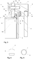
- Fig. 3 illustrates the locking device 4 when it is in its closed position and the door 3 is firmly pressed against the container 2.
- the locking device 4 comprises a stop pin 10 (see Fig. 2 ) that co-rotates with the base portion 7 upon rotation of the base portion 7.
- the locking device 4 also comprises a stationary plug 18 that is arranged to engage the stop pin 10 when the locking device 4 is in the open position, thereby preventing further rotation of the base portion 7.
- the stop pin 10 and the stationary plug 18 provides an "open stop" function so that an operator opening the door 3 becomes aware of when the sliding pin 5 is not longer engaged by the engagement surface 9, i.e. when the locking device 4 has been transferred to its open position.
- the open stop pin 10 is in this example arranged to extend in a direction other than the direction of the handle 8, such as a direction perpendicular to the handle 8. This may facilitate the function of the stop pin 10, e.g. by allowing the stop pin 10 to engage the stationary plug 18 arranged on the flange 19.
- the stop pin 10 and the stationary plug 18 are arranged on a first side 14a of the flange 14 and the base portion 7 is arranged on a second side 14b of the flange 14 that is opposite the first side 14a.
- the door 3 may also be arranged on the second side 14b of the flange via suitable hinges.
- the first side 14a may be a side not facing the door 3
- second side 14b may be a side of the flange 14 that faces the door 14. Consequently, the handle 8 is arranged on the outside side 14b of the flange 14, i.e. on the same side of the flange 14 as the door 3.
- the base portion 7 comprises a shaft 15 extending through the flange 14 for providing co-rotation of the stop pin 10 upon rotation of the base portion 7.
- the shaft 15 is connected to the base portion 7 and the bearing 22 is formed as a hole in the flange 14, at a position where the shaft 15 extends through the flange 14. This allows for rotation of the base portion 7 relative the flange 14 upon rotation of the handle 8 around rotational axis A extending through the shaft 15.
- the shaft 15 is surrounded by plastic portions 16, 17 on both sides of the flange 14. These plastic portions 16,17 are arranged to engage the surfaces of the flange 14 upon rotation of the base portion 7.
- the flange 14 may be made of metal, such as stainless steel, and the plastic portions 16, 17 may reduce the friction against the flange 14 upon rotation of the handle 8.
- the plastic portion 17 arranged to be on the same side of the flange 19 as the handle 8 is a plastic washer that may have friction reducing agents incorporated in its plastic composition.
- the plastic portion 16 arranged to be on the same side of the flange 14 as the stop pin 10 may have the principal shape of a washer, also having friction reducing agents incorporated in its plastic composition.
- the paddle mixer 1 further comprises a seal 12 that is arranged between the container 2 and the door 3 when the locking device 4 is in its closed position.
- the seal 12 is in this embodiment a lip seal that is pressed between door 3 and container 2 upon closing of the door 2.
- the seal 12 may be made of silicone.
- the seal 12 is arranged around the whole circumference of the opening 19 to the container 2 so that a proper seal is formed between the door 3 and the container 2.
- the seal 12 rests against an outer surface 23 of the container 3 that is located between the second side 14b of the flange 14 and the opening 19 to the container.
- the seal 12 is held in place by a plurality of seal pins 13 having shoulders 20 that are pressed into the seal 12 to secure the position of the seal 12 when the door 3 is open.
- the seal pins 13 may be arranged on the outer second surface 14b of the flange 14 so that the shoulders 14 are pressed into the seal 12, to thereby press the seal 12 against the outer surface 23 of the container 2.
- the outer surface 23 is in this case perpendicular to the second side 14b of the flange 14.
- the seal 12 may be a lip seal that comprises a base portion 12a and a lip portion 12b.
- the lip seal 12 may then be arranged such that the lip portion 12b seals between the door 3 and the container 2, and the seal pins 13 are pressed into the base portion 12a of the lip seal.
- the lip portion 12b may have a tip shaped cross-section, i.e. it may have a cross-section that becomes more and more narrow the further away from the base portion 12a it gets. This may facilitate compression of the seal 12 when closing the door 3.
- the locking device 4 comprises a stationary sliding pin 5 and a rotational unit 6 arranged to receive the sliding pin 5, and the rotational unit 6 comprises a base portion 7 and a handle 8 for rotating the base portion 7 in relation to the sliding pin 5.
- the base portion 7 further comprises an engagement surface 9 for slidable engagement with the sliding pin 5, and this engagement with the sliding pin 5 transforms the locking device 4 from an open to a closed position.
- the engagement surface 9 is located in the base portion 7, which may be rotated in a rotational plane by handle 8.
- This rotational plane is thus parallel to e.g. the second side of the flange 14b when the rotational unit is arranged on the flange 14, or parallel to the door 3 if the rotational unit is arranged on the door.
- the rotational unit 6 may thus be rotated around rotational axis A that extends perpendicular to the handle 8 and through the shaft 15 of the base portion 7.
- the engagement surface 9 is inclined such that a force applied on the sliding pin 5 by the engagement surface 9 gradually increases when the base portion 7 is rotated in relation to the sliding pin 5, to thereby press and seal the door 3 against the container 2. Consequently, the engagement surface 9 is inclined with respect to the rotational plane of the base rotational unit 6. This inclination may at an average be in the order of 3,5 to 6,2 degrees to provide a suitable increase in the pressing force applied to the sliding pin 5 upon transferring the locking device 4 from its open to its closed position.
- the engagement surface 9 and the sliding pin 5 may further be arranged and/or dimensioned so that a predetermined frictional force is obtained between the sliding pin 5 and the engagement surface 9.
- the engagement surface 9 may comprise a concave shape as seen along the extension of the engagement surface 9. This may allow for a suitable friction against e.g. a rounded sliding pin 5, i.e. a sliding pin 5 having a convex outer surface that slides and is pressed against a concave engagement surface 9.
- the engagement surface 9 typically has a curved shape as seen in the rotational plane of the base portion 7.
- the engagement surface 9 is curved as seen in the projection of the rotational plane of the handle 8. This is for allowing a smooth movement of the sliding pin 5 within the engagement surface 9 when the handle 8 is rotated.
- the engagement surface 9 may comprise a part that has a partially helical shape that extends a certain number of degrees around the helical axis, such as between 90 and 270 degrees.
- the engagement surface 9 may thus as a whole be partially helically shaped to extend a certain number of degrees around the helical axis, which in the illustrated embodiment is the rotational axis A.
- the engagement surface 9 has in the illustrated embodiment a first part 9a having a first inclination ⁇ and arranged where the sliding pin 5 enters and slides into the engagement surface 9.
- This first part has a partly helical shape with a helical axis that is aligned with the rotational axis A of the rotational unit 6.
- the first part 9a spirals around rotational axis A.
- the first inclination ⁇ has an angle of 3,5 to 6,2 degrees.
- the first inclination angle ⁇ allows for a suitable increase in the pressing force applied to the sliding pin 5 as it enters and slides along the first part 9a of the engagement surface 9.
- the engagement surface 9 has a second part 9b having a second inclination ⁇ and arranged at an end of the engagement surface 9, after the first part 9a as seen in the rotational direction R of the base portion 7.
- the second part 9b is arranged about 135 degrees from the beginning of the first part 9a of the engagement surface 9, i.e. a sliding pin 5 will be pressed against the first part 9a of the engagement surface during a 135 degree turn of the handle 8 before entering the second part 9b having the second inclination ⁇ .
- the second inclination ⁇ is opposite the first inclination ⁇ , such that the force applied on the sliding pin 5 by the engagement surface 9 decreases when the sliding pin 5 enters the second part 9b, thereby providing a self-locking mechanism when the sliding pin 5 has entered the second part 9b.
- the second inclination ⁇ being "opposite" the first inclination may be understood as second inclination ⁇ having a negative angular value while the first inclination ⁇ has a positive angular value (or the other way around).
- the absolute value of the second inclination ⁇ may be less than the absolute value of the first inclination ⁇ .
- the first inclination ⁇ may have an angle of 3,5 to 6,2 degrees
- the second inclination ⁇ may have an angle of -2,2 to -4,8 degrees.
- the sliding pin 5 is, as seen along the axis of rotation A of the base portion 7 and when the engagement surface 9 slidably engages the sliding pin 5, located between the base portion 7 and a support member 14 that supports the base portion 7.
- the support is accomplished by the base portion 7 being, either directly or indirectly via the shaft 15, connected to the support member 14.
- the support member 14 is in this embodiment the flange 14 that extends around the opening 19 to the container 2.
- a distance D between the engagement surface 9 and the support member 14 gradually decreases when the sliding pin 5 slides along the first part 9a of the engagement surface 9 upon rotation of the base portion 7, to thereafter increase when the sliding pin 5 enters the second part 9b of the engagement surface 9. This provides the locking mechanism of the device 4.
- the rotational unit 6 comprises the shaft 15 that defines the axis of rotation A of the base portion 7, and the engagement surface 9 comprises a partially helical shape with an end portion 9b that is, as seen in a longitudinal direction of the handle 8, located between the shaft 15 and the handle 8.
- the axis of rotation A is thus perpendicular to the extension of the handle 8.
- the engagement surface 9 has its end portion 9b located at in the base portion 7 close to where the shaft 8 is welded to the base portion, and the engagement surface 9 has its start at least 90 degrees, as seen in the rotational direction R of the base portion 7, from its end portion 9b.
- the base portion 7 is partly cylindrical and has a circular shape as seen in the rotational plane of the rotational unit 6, with a center line, illustrated by C in Fig. 7 , parallel to the axis of rotation A but shifted relative the axis of rotation A.
- the center C of the base portion 7 is shifted so that it is not aligned with rotational axis A but instead located between the shaft 15 and the position of the base portion 7 from where the handle 8 extends. This shift makes the rotational unit 6 more compact.
- Figs 8 and 9 illustrates the sliding pin 5.
- the sliding pin 5 comprises a plastic portion 11 on which the force from the engagement surface 9 is applied. This plastic portion 11 is thus pressed by the engagement surface 9.
- the base portion 7, as well as the engagement surface 9, the handle 8 and the shaft 15 of the rotational unit 6, may comprise a metal, such as stainless steel.
- the plastic portion 11 may thus be pressed against an engagement surface of metal, such as stainless steel, upon opening and closing of the locking device 4.
- the interface between the plastic portion and the stainless steel may provide a suitable friction coefficient upon rotation of the handle 8 and sliding of the sliding pin 5 against engagement surface 9.
- the plastic portion 11 may comprises PEEK (polyether ether ketone). This polymer has for the described locking device 4 been found to provide suitable friction against the engagement surface 9.
- the plastic portion 11 may have a rounded outer surface, as seen in Figs 8 and 9 . This may further facilitate the sliding motion against the engagement surface 9.
- the rounded surface may have a radius that is from 8 mm to 12 mm.
- the locking device 4 is free of any threads but may still efficiently be transferred from an open position to a closed position. Being free of threads is advantageous especially when it comes to handling powdery material, since the powder may be stuck on or between small surfaces of threads.
Landscapes
- Chemical & Material Sciences (AREA)
- Chemical Kinetics & Catalysis (AREA)
- Engineering & Computer Science (AREA)
- Mechanical Engineering (AREA)
- Closures For Containers (AREA)
- Food Preservation Except Freezing, Refrigeration, And Drying (AREA)
Abstract
Description
- The invention relates to a food handling apparatus having locking devices for sealing a door of the food handling apparatus.
- Food processing is a technology that sets high demands on process hygiene and quality, and typically involves several complex activities such as emulsification, pasteurization and mixing, all performed in large-scale food processing equipment.
- Paddle mixers are used in food industry due to the combination of high sanitary standards and the need for mixing or dispersing high quantities of e.g. powder and liquid ingredients into a liquid medium to efficiently achieve a smooth, homogenous product with consistent quality. Paddle mixers are large instruments and may be equipped with twin shaft paddles.
- However, food handling equipment, such as paddle mixers, used in large scale food processing requires quick and safe dismounting of openings, often performed manually, combined with a hygienic design.
- Several techniques for providing good operability of food handling equipment in terms of opening and closing large doors to containers exist on the market today. However, there are issues with prior art solutions in that they are not fully ergonomic, i.e. it may take a long time to open the door, the design may not fulfill all hygienic standards and the seals used may be damaged due to uneven compression applied when closing the door.
- It is an object of the invention to at least partly overcome one or more limitations of the prior art. In particular, it is an object to provide a food handling apparatus having an ergonomic design for opening and closing the door that fulfills high hygienic demands. In one aspect of the invention, this is achieved by a food handling apparatus that comprises: a container; a door for allowing access to the container; and at least one locking device for sealing the door against the container. The locking device comprises a stationary sliding pin and a rotational unit arranged to receive the sliding pin, wherein either the sliding pin or the rotational unit is arranged on the door whereas the other is arranged on the container. The rotational unit comprises a base portion and a handle for rotating the base portion in relation to the sliding pin, the base portion comprises an engagement for slidable engagement with the sliding pin, and the engagement surface is inclined such that a force applied on the sliding pin by the engagement surface gradually increases when the base portion is rotated in relation to the sliding pin, to thereby press and seal the door against the container.
- The food handling apparatus is advantageous in that it provides an ergonomic solution for opening large, heavy doors without using any tool. The food handling apparatus may comprise several, such as at least five, locking devices of the same type for sealingly closing the door to the container. As an example, the design of the locking devices may provide for a single operator to quickly open a two meter wide door without the use of any tools. Furthermore, the locking device of the food handling apparatus may be designed with few or no threads within the container. This is advantageous since threads may wear down over time and be a source of contamination.
- The engagement surface may have a curved shape as seen in the rotational plane of the base portion.
- Furthermore, the engagement surface may comprise a first part having a first inclination and arranged where the sliding pin enters and slides into the engagement surface
- The engagement surface may thus be inclined with respect to the rotational plane of the base portion. This facilitates an gradually increased force being applied on the sliding pin by the engagement surface when the base portion is rotated in relation to the sliding pin. With such a shape of the engagement surface, there may be an even pressure applied on a seal that may be used between door and container when the locking device is transferred form an open to a closed position.
- The engagement surface may comprise a second part having a second inclination and arranged at an end of the engagement surface, after the first part as seen in a rotational direction of the base portion.
- The second inclination may be opposite the first inclination, such that the force applied on the sliding pin by the engagement surface decreases when the sliding pin enters the second part, thereby providing a self-locking mechanism when the sliding pin has entered the second part.
- The self-locking mechanism thus provides for the door being firmly in place once the locking device has been transferred to its closed position. Further, with the self-locking mechanism, a certain threshold force is required on the handle when the locking device is in its closed position in order for the sliding pin to slide out of engagement with the engagement surface, i.e. for the locking device to be transferred back to its open position.
- The sliding pin may comprise a plastic portion, e.g. comprising PEEK (polyether ether ketone) on which the force from the engagement surface is applied. Further, the engagement surface may comprise a metal, such as stainless steel.
- Using a plastic portion that slides on a stainless steel surface may give rise to a friction that is within a preferred interval, i.e. it may at the same time provide sliding of the pin on the engagement surface and prevent the pin from accidentally sliding out of engagement with the engagement surface.
- The sliding pin may be of metal whereas the engagement surface, or at least part of the engagement surface, may comprise a plastic, such as PEEK, to provide a desired plastic-to-metal friction coefficient.
- Still other objectives, features, aspects and advantages of the invention will appear from the following detailed description as well as from the drawings.
- Embodiments of the invention will now be described, by way of example, with reference to the accompanying schematic drawings.
-
Fig. 1 is a perspective view of a food handling apparatus with locking devices. -
Fig. 2 is a perspective view of a locking device. -
Fig. 3 is a cross-sectional view of the locking device ofFig. 2 . -
Fig. 4 is a perspective view of a rotational unit of the locking device ofFig. 2 . -
Fig. 5 is a side view of the rotational unit ofFig 4 . -
Fig. 6 is another side view of the rotational unit ofFig 4 . -
Fig. 7 is a top view of the rotational unit ofFig 4 . -
Fig. 8 is a side view of a sliding pin of the locking device ofFig. 2 . -
Fig. 9 is a top view of the sliding pin ofFig. 8 . - Embodiments of the invention will now be described more fully hereinafter with reference to the accompanying drawings, in which some, but not all, embodiments of the invention are shown. The invention may be embodied in many different forms and should not be construed as limited to the embodiments set forth herein.
- With reference to
Fig. 1 an exemplary food handling apparatus is illustrated. The food handling apparatus is in this embodiment apaddle mixer 1 having acontainer 2 and alarge door 3 for accessing thecontainer 2 viaopening 19. Thedoor 3 and thecontainer 2 are thus arranged to be closable against each other. The paddle mixer further comprisestwin paddles paddle mixer 1 comprises a plurality of lockingdevices 4 for sealing thedoor 3 against thecontainer 2. In this case, thepaddle mixer 1 comprises ninelocking devices 4, more or less evenly distributed around theopening 19 to thecontainer 2. - With further reference to
Figs 2 and3 , each lockingdevice 4 comprises a stationary slidingpin 5 and arotational unit 6 for receiving the slidingpin 5 as thelocking device 4 seals thedoor 3 to thecontainer 2. - The sliding pins 5 are in this embodiment arranged on the
door 3 and therotational units 6 are arranged on thecontainer 2. To be more specific, the rotational units are arranged on aflange 14 of thecontainer 2 that surrounds theopening 19 of thecontainer 2, whereas the slidingpins 5 are arranged on the outside surface of thedoor 3. Therotational units 6locking devices 4 are arranged on thesurface 14b of the flange that faces thedoor 3. - However, it is to be understood that the positioning of the
rotational elements 6 and the slidingpins 5 could be the other way around, i.e. so that therotational elements 6 are arranged on thedoor 3 and the slidingpins 5 are arranged on thecontainer 3, for example on theflange 14. - Further, the
paddle mixer 1 comprises aseal 12 that surrounds theopening 19 to thecontainer 2 and provides a sealing function as thedoor 3 is pressed to thecontainer 2 by thelocking devices 4. - The
rotational unit 6 of lockingdevice 4 comprises abase portion 7 that is arranged on thecontainer 2 via abearing 22 arranged in theflange 14. - A
handle 8 is welded to thebase portion 7 and is used for rotating thebase portion 7 in relation to thecontainer 2 via thebearing 22. - The
base portion 7 andbearing 22 are thus arranged so that thebase portion 7 can rotate in a rotational plane parallel to the surface to which thebase portion 7 is attached via the plain bearing, i.e. theouter surface 14b offlange 14. - In this way, the
handle 8 allows for rotation of thebase portion 7 relative to the slidingpin 5 around rotational axis A perpendicular to theouter surface 14b of theflange 14. - The
locking device 4 may be transferred from an open position in which thedoor 3 is not sealed against thecontainer 2 and the slidingpin 5 is not in engagement with anengagement surface 9 of thebase portion 7, to a closed position in which thedoor 3 is sealed against thecontainer 2 and the slidingpin 5 is subjected to a force from theengagement surface 9. Transfer between open and closed position is achieved by rotation of thehandle 8 to make the slidingpin 5 enter and engage theengagement surface 9. - The sliding
pin 5 is arranged on thedoor 3 close to the outer circumference of thedoor 3 so that it may be easily received by therotational unit 6 upon rotation of thehandle 8. The slidingpin 5 is held in place on thedoor 3 bypin housing 5a that surrounds a base of the slidingpin 5. The interaction between slidingpin 5 and theengagement surface 9 is further described in relation toFigs. 4-7 . As may be seen,Fig. 3 illustrates thelocking device 4 when it is in its closed position and thedoor 3 is firmly pressed against thecontainer 2. - The
locking device 4 comprises a stop pin 10 (seeFig. 2 ) that co-rotates with thebase portion 7 upon rotation of thebase portion 7. Thelocking device 4 also comprises astationary plug 18 that is arranged to engage thestop pin 10 when thelocking device 4 is in the open position, thereby preventing further rotation of thebase portion 7. - Thus, the
stop pin 10 and thestationary plug 18 provides an "open stop" function so that an operator opening thedoor 3 becomes aware of when the slidingpin 5 is not longer engaged by theengagement surface 9, i.e. when thelocking device 4 has been transferred to its open position. - The
open stop pin 10 is in this example arranged to extend in a direction other than the direction of thehandle 8, such as a direction perpendicular to thehandle 8. This may facilitate the function of thestop pin 10, e.g. by allowing thestop pin 10 to engage thestationary plug 18 arranged on theflange 19. - As best seen in
Fig. 3 , thestop pin 10 and thestationary plug 18 are arranged on afirst side 14a of theflange 14 and thebase portion 7 is arranged on asecond side 14b of theflange 14 that is opposite thefirst side 14a. Thedoor 3 may also be arranged on thesecond side 14b of the flange via suitable hinges. Thus, thefirst side 14a may be a side not facing thedoor 3, whereassecond side 14b may be a side of theflange 14 that faces thedoor 14. Consequently, thehandle 8 is arranged on theoutside side 14b of theflange 14, i.e. on the same side of theflange 14 as thedoor 3. - The
base portion 7 comprises ashaft 15 extending through theflange 14 for providing co-rotation of thestop pin 10 upon rotation of thebase portion 7. Theshaft 15 is connected to thebase portion 7 and thebearing 22 is formed as a hole in theflange 14, at a position where theshaft 15 extends through theflange 14. This allows for rotation of thebase portion 7 relative theflange 14 upon rotation of thehandle 8 around rotational axis A extending through theshaft 15. - The
shaft 15 is surrounded byplastic portions flange 14. Theseplastic portions flange 14 upon rotation of thebase portion 7. - The
flange 14 may be made of metal, such as stainless steel, and theplastic portions flange 14 upon rotation of thehandle 8. Theplastic portion 17 arranged to be on the same side of theflange 19 as thehandle 8 is a plastic washer that may have friction reducing agents incorporated in its plastic composition. Further, theplastic portion 16 arranged to be on the same side of theflange 14 as thestop pin 10 may have the principal shape of a washer, also having friction reducing agents incorporated in its plastic composition. - The
paddle mixer 1 further comprises aseal 12 that is arranged between thecontainer 2 and thedoor 3 when thelocking device 4 is in its closed position. Theseal 12 is in this embodiment a lip seal that is pressed betweendoor 3 andcontainer 2 upon closing of thedoor 2. When thedoor 2 is closed a static seal that functions much like a gasket between two flanges is provided. Theseal 12 may be made of silicone. - The
seal 12 is arranged around the whole circumference of theopening 19 to thecontainer 2 so that a proper seal is formed between thedoor 3 and thecontainer 2. In this embodiment, theseal 12 rests against anouter surface 23 of thecontainer 3 that is located between thesecond side 14b of theflange 14 and theopening 19 to the container. Theseal 12 is held in place by a plurality of seal pins 13 havingshoulders 20 that are pressed into theseal 12 to secure the position of theseal 12 when thedoor 3 is open. - The seal pins 13 may be arranged on the outer
second surface 14b of theflange 14 so that theshoulders 14 are pressed into theseal 12, to thereby press theseal 12 against theouter surface 23 of thecontainer 2. Theouter surface 23 is in this case perpendicular to thesecond side 14b of theflange 14. - The
seal 12 may be a lip seal that comprises abase portion 12a and alip portion 12b. Thelip seal 12 may then be arranged such that thelip portion 12b seals between thedoor 3 and thecontainer 2, and the seal pins 13 are pressed into thebase portion 12a of the lip seal. - As seen in the cross-section of the
lip seal 12 inFig. 3 , thelip portion 12b may have a tip shaped cross-section, i.e. it may have a cross-section that becomes more and more narrow the further away from thebase portion 12a it gets. This may facilitate compression of theseal 12 when closing thedoor 3. - As discussed above, the
locking device 4 comprises a stationary slidingpin 5 and arotational unit 6 arranged to receive the slidingpin 5, and therotational unit 6 comprises abase portion 7 and ahandle 8 for rotating thebase portion 7 in relation to the slidingpin 5. Thebase portion 7 further comprises anengagement surface 9 for slidable engagement with the slidingpin 5, and this engagement with the slidingpin 5 transforms thelocking device 4 from an open to a closed position. - With reference to
Figs 4-7 , theengagement surface 9 is located in thebase portion 7, which may be rotated in a rotational plane byhandle 8. This rotational plane is thus parallel to e.g. the second side of theflange 14b when the rotational unit is arranged on theflange 14, or parallel to thedoor 3 if the rotational unit is arranged on the door. Therotational unit 6 may thus be rotated around rotational axis A that extends perpendicular to thehandle 8 and through theshaft 15 of thebase portion 7. - The
engagement surface 9 is inclined such that a force applied on the slidingpin 5 by theengagement surface 9 gradually increases when thebase portion 7 is rotated in relation to the slidingpin 5, to thereby press and seal thedoor 3 against thecontainer 2. Consequently, theengagement surface 9 is inclined with respect to the rotational plane of the baserotational unit 6. This inclination may at an average be in the order of 3,5 to 6,2 degrees to provide a suitable increase in the pressing force applied to the slidingpin 5 upon transferring thelocking device 4 from its open to its closed position. - The
engagement surface 9 and the slidingpin 5 may further be arranged and/or dimensioned so that a predetermined frictional force is obtained between the slidingpin 5 and theengagement surface 9. Theengagement surface 9 may comprise a concave shape as seen along the extension of theengagement surface 9. This may allow for a suitable friction against e.g. a rounded slidingpin 5, i.e. a slidingpin 5 having a convex outer surface that slides and is pressed against aconcave engagement surface 9. - The
engagement surface 9 typically has a curved shape as seen in the rotational plane of thebase portion 7. Thus, theengagement surface 9 is curved as seen in the projection of the rotational plane of thehandle 8. This is for allowing a smooth movement of the slidingpin 5 within theengagement surface 9 when thehandle 8 is rotated. - As an example, the
engagement surface 9 may comprise a part that has a partially helical shape that extends a certain number of degrees around the helical axis, such as between 90 and 270 degrees. Theengagement surface 9 may thus as a whole be partially helically shaped to extend a certain number of degrees around the helical axis, which in the illustrated embodiment is the rotational axis A. - The
engagement surface 9 has in the illustrated embodiment afirst part 9a having a first inclination α and arranged where the slidingpin 5 enters and slides into theengagement surface 9. This first part has a partly helical shape with a helical axis that is aligned with the rotational axis A of therotational unit 6. Thus, thefirst part 9a spirals around rotational axis A. - As seen relative a rotational plane of the
base portion 7, the first inclination α has an angle of 3,5 to 6,2 degrees. The first inclination angle α allows for a suitable increase in the pressing force applied to the slidingpin 5 as it enters and slides along thefirst part 9a of theengagement surface 9. - The
engagement surface 9 has asecond part 9b having a second inclination β and arranged at an end of theengagement surface 9, after thefirst part 9a as seen in the rotational direction R of thebase portion 7. - The
second part 9b is arranged about 135 degrees from the beginning of thefirst part 9a of theengagement surface 9, i.e. a slidingpin 5 will be pressed against thefirst part 9a of the engagement surface during a 135 degree turn of thehandle 8 before entering thesecond part 9b having the second inclination β. - Furthermore, the second inclination β is opposite the first inclination α, such that the force applied on the sliding
pin 5 by theengagement surface 9 decreases when the slidingpin 5 enters thesecond part 9b, thereby providing a self-locking mechanism when the slidingpin 5 has entered thesecond part 9b. The second inclination β being "opposite" the first inclination may be understood as second inclination β having a negative angular value while the first inclination α has a positive angular value (or the other way around). - This accomplish a self-locking mechanism when the
locking device 4 is in its closed position. This is achieved due to the inclination of theengagement surface 9 changing direction at the end of theengagement surface 9, i.e. at thesecond part 9b of the engagement surface at which the slidingpin 5 resides when thelocking device 4 is in its closed position. Since the second inclination β is in a direction that is opposite the direction of the first inclination α, aridge 9c is formed between thefirst part 9a and thesecond part 9b. Thus, the slidingpin 5 first slides within thefirst part 9a upon engagement with theengagement surface 9, then slides overridge 9c before entering thesecond part 9b when thelocking device 4 is in its closed position and thedoor 3 is sealed to thecontainer 2. Due to the opposite direction of the second inclination β, the force applied on the slidingpin 5 is decreased when it enters thesecond part 9b (the closed position). Rotational force is then required to transfer the locking device back to its open position again, i.e. to open the door, since the slidingpin 5 then first will be subjected to higher force in order to slide over theridge 9c before sliding out of theengagement surface 9 via thefirst part 9a. - The absolute value of the second inclination β may be less than the absolute value of the first inclination α. As an example the first inclination α may have an angle of 3,5 to 6,2 degrees, and the second inclination β may have an angle of -2,2 to -4,8 degrees.
- As further seen in
Fig. 3 , the slidingpin 5 is, as seen along the axis of rotation A of thebase portion 7 and when theengagement surface 9 slidably engages the slidingpin 5, located between thebase portion 7 and asupport member 14 that supports thebase portion 7. The support is accomplished by thebase portion 7 being, either directly or indirectly via theshaft 15, connected to thesupport member 14. Thesupport member 14 is in this embodiment theflange 14 that extends around theopening 19 to thecontainer 2. - As understood from above, a distance D between the
engagement surface 9 and thesupport member 14 gradually decreases when the slidingpin 5 slides along thefirst part 9a of theengagement surface 9 upon rotation of thebase portion 7, to thereafter increase when the slidingpin 5 enters thesecond part 9b of theengagement surface 9. This provides the locking mechanism of thedevice 4. - Furthermore, as seen in the top view of
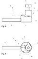
Fig. 7 , therotational unit 6 comprises theshaft 15 that defines the axis of rotation A of thebase portion 7, and theengagement surface 9 comprises a partially helical shape with anend portion 9b that is, as seen in a longitudinal direction of thehandle 8, located between theshaft 15 and thehandle 8. The axis of rotation A is thus perpendicular to the extension of thehandle 8. Thus, theengagement surface 9 has itsend portion 9b located at in thebase portion 7 close to where theshaft 8 is welded to the base portion, and theengagement surface 9 has its start at least 90 degrees, as seen in the rotational direction R of thebase portion 7, from itsend portion 9b. Further, thebase portion 7 is partly cylindrical and has a circular shape as seen in the rotational plane of therotational unit 6, with a center line, illustrated by C inFig. 7 , parallel to the axis of rotation A but shifted relative the axis of rotation A. In this embodiment, the center C of thebase portion 7 is shifted so that it is not aligned with rotational axis A but instead located between theshaft 15 and the position of thebase portion 7 from where thehandle 8 extends. This shift makes therotational unit 6 more compact. -
Figs 8 and 9 illustrates the slidingpin 5. The slidingpin 5 comprises aplastic portion 11 on which the force from theengagement surface 9 is applied. Thisplastic portion 11 is thus pressed by theengagement surface 9. - The
base portion 7, as well as theengagement surface 9, thehandle 8 and theshaft 15 of therotational unit 6, may comprise a metal, such as stainless steel. Theplastic portion 11 may thus be pressed against an engagement surface of metal, such as stainless steel, upon opening and closing of thelocking device 4. The interface between the plastic portion and the stainless steel may provide a suitable friction coefficient upon rotation of thehandle 8 and sliding of the slidingpin 5 againstengagement surface 9. - As an example, the
plastic portion 11 may comprises PEEK (polyether ether ketone). This polymer has for the describedlocking device 4 been found to provide suitable friction against theengagement surface 9. - Moreover, the
plastic portion 11 may have a rounded outer surface, as seen inFigs 8 and 9 . This may further facilitate the sliding motion against theengagement surface 9. The rounded surface may have a radius that is from 8 mm to 12 mm. - As mentioned, the
locking device 4 is free of any threads but may still efficiently be transferred from an open position to a closed position. Being free of threads is advantageous especially when it comes to handling powdery material, since the powder may be stuck on or between small surfaces of threads. - From the description above follows that, although various embodiments of the invention have been described and shown, the invention is not restricted thereto, but may also be embodied in other ways within the scope of the subject-matter defined in the following claims.
Claims (15)
- A food handling apparatus (1) comprising
a container (2),
a door (3) for allowing access to the container (2), and
at least one locking device (4) for sealing the door (3) against the container (2), the locking device (4) comprising a stationary sliding pin (5) and a rotational unit (6) arranged to receive the sliding pin (5), wherein either the sliding pin (5) or the rotational unit (6) is arranged on the door (3) whereas the other is arranged on the container (2), wherein
the rotational unit (6) comprises a base portion (7) and a handle (8) for rotating the base portion (7) in relation to the sliding pin (5),
the base portion (7) comprises an engagement surface (9) for slidable engagement with the sliding pin (5), and
the engagement surface (9) is inclined such that a force applied on the sliding pin (5) by the engagement surface (9) gradually increases when the base portion (7) is rotated in relation to the sliding pin (5), to thereby press and seal the door (3) against the container (2). - A food handling apparatus (1) according to claim 1, wherein the engagement surface (9) has a curved shape as seen in the rotational plane of the base portion (7).
- A food handling apparatus (1) according to any previous claim, wherein the engagement surface (9) comprises
a first part (9a) having a first inclination (α) and arranged where the sliding pin (5) enters and slides into the engagement surface (9), and
a second part (9b) having a second inclination (β) and arranged at an end of the engagement surface (9), after the first part (9a) as seen in a rotational direction (R) of the base portion (7), wherein
the second inclination (β) is opposite the first inclination (α), such that the force applied on the sliding pin (5) by the engagement surface (9) decreases when the sliding pin (5) enters said second part (9b), thereby providing a self-locking mechanism when the sliding pin (5) has entered the second part (9b). - A food handling apparatus (1) according to claim 3, wherein, as seen relative a rotational plane of the base portion (7),
the first inclination (α) has an angle of 3,5 to 6,2 degrees, and
the second inclination (β) has an angle of -2,2 to -4,8 degrees. - A food handling apparatus (1) according to any one of claims 2-4, wherein
the sliding pin (5) is, as seen along an axis of rotation (A) of the base portion (7) and when the engagement surface (9) slidably engages the sliding pin (5), located between the base portion (7) and a support member (14) that supports the base portion (7), and
a distance (D) between the engagement surface (9) and the support member (14) gradually decreases when the sliding pin (5) slides along the first part (9a) of the engagement surface (9) upon rotation of the base portion (7), to thereafter increase when the sliding pin (5) enters the second part (9b) of the engagement surface (9). - A food handling apparatus (1) according to any one of claims 2-5, wherein
the rotational unit (6) comprises a shaft (15) that defines an axis of rotation (A) of the base portion (7), and
the engagement surface (9) comprises a partially helical shape with an end portion (9b) that is, as seen in a longitudinal direction of the handle (8), located between the shaft (15) and the handle (8). - A food handling apparatus (1) according to any previous claim, wherein the locking device (4) comprises
a stop pin (10) that co-rotates with the base portion (7) upon rotation of the base portion (7), and
a stationary plug (18) that is arranged to engage the stop pin (10) when the locking device (4) is in the open position, thereby preventing further rotation of the base portion (7). - A food handling apparatus (1) according to any previous claim, wherein
the sliding pin (5) comprises a plastic portion (11) on which the force from the engagement surface (9) is applied, and
the engagement surface (9) comprises a metal. - A food handling apparatus (1) according to claim 8, wherein the plastic portion (11) comprises PEEK (polyether ether ketone).
- A food handling apparatus according to any previous claim, comprising
a seal (12) that is arranged between the container (2) and the door (3) when the locking device (4) is in its closed position, and
a plurality of seal pins (13) having shoulders (20) that are pressed into the seal (12) to secure the position of the seal (12) when the door (3) is open. - A food handling apparatus (1) according to claim 10, wherein
the seal (12) is a lip seal comprising a base portion (12a) and a lip portion (12b),
the lip seal is arranged such that the lip portion (12b) seals between the door (3) and the container (2), and
the seal pins (13) are pressed into the base portion (12a) of the lip seal. - A food handling apparatus (1) according to any previous claim, wherein the sliding pin (5) is arranged on the door (3) and the rotational unit (6) is arranged on the container (2).
- A food handling apparatus (1) according to claim 12, wherein
the container (2) comprises a flange (14) arranged around the opening (19), and
the rotational unit (6) is arranged on the flange (14). - A food handling apparatus (1) according to claim 7 and 13, wherein
the stop pin (10) and the stationary plug (18) are arranged on a first side (14a) of the flange (14),
the base portion (7) is arranged on a second side (14b) of the flange (14) that is opposite said first side (14a), and
the base portion (7) comprises a shaft (15) extending through the flange (14) for providing co-rotation of the stop pin (10) upon rotation of the base portion (7). - A food handling apparatus (1) according to claim 14, wherein the shaft (15) is surrounded by plastic portions (16, 17) on both sides of the flange (14), wherein the plastic portions (16,17) are arranged to engage the surfaces of the flange (14) upon rotation of the base portion (7).
Applications Claiming Priority (1)
| Application Number | Priority Date | Filing Date | Title |
|---|---|---|---|
| EP17201145 | 2017-11-10 |
Publications (2)
| Publication Number | Publication Date |
|---|---|
| EP3483362A1 true EP3483362A1 (en) | 2019-05-15 |
| EP3483362B1 EP3483362B1 (en) | 2023-11-01 |
Family
ID=60320715
Family Applications (1)
| Application Number | Title | Priority Date | Filing Date |
|---|---|---|---|
| EP18204476.8A Active EP3483362B1 (en) | 2017-11-10 | 2018-11-06 | Food handling apparatus with locking device |
Country Status (4)
| Country | Link |
|---|---|
| EP (1) | EP3483362B1 (en) |
| AU (1) | AU2018363679B2 (en) |
| NZ (1) | NZ763427A (en) |
| WO (1) | WO2019091933A1 (en) |
Citations (5)
| Publication number | Priority date | Publication date | Assignee | Title |
|---|---|---|---|---|
| DE9421449U1 (en) * | 1994-06-11 | 1995-11-23 | Steinbach & Vollmann GmbH & Co., 42579 Heiligenhaus | Device door lock |
| US20060220392A1 (en) * | 2005-03-30 | 2006-10-05 | Sanyo Electric Co., Ltd. | Door unit for cold storage |
| US20070158956A1 (en) * | 2005-10-28 | 2007-07-12 | Jui Hung Refrigeration Technology Co., Ltd. | Pressurized handle set |
| WO2016033505A1 (en) * | 2014-08-29 | 2016-03-03 | Deka Products Limited Partnership | Door latch |
| US20170284143A1 (en) * | 2016-04-04 | 2017-10-05 | Global Cooling, Inc. | Door Latch With Opening And Closing Mechanical Advantage |
-
2018
- 2018-11-06 EP EP18204476.8A patent/EP3483362B1/en active Active
- 2018-11-06 AU AU2018363679A patent/AU2018363679B2/en active Active
- 2018-11-06 WO PCT/EP2018/080221 patent/WO2019091933A1/en not_active Ceased
- 2018-11-06 NZ NZ763427A patent/NZ763427A/en unknown
Patent Citations (5)
| Publication number | Priority date | Publication date | Assignee | Title |
|---|---|---|---|---|
| DE9421449U1 (en) * | 1994-06-11 | 1995-11-23 | Steinbach & Vollmann GmbH & Co., 42579 Heiligenhaus | Device door lock |
| US20060220392A1 (en) * | 2005-03-30 | 2006-10-05 | Sanyo Electric Co., Ltd. | Door unit for cold storage |
| US20070158956A1 (en) * | 2005-10-28 | 2007-07-12 | Jui Hung Refrigeration Technology Co., Ltd. | Pressurized handle set |
| WO2016033505A1 (en) * | 2014-08-29 | 2016-03-03 | Deka Products Limited Partnership | Door latch |
| US20170284143A1 (en) * | 2016-04-04 | 2017-10-05 | Global Cooling, Inc. | Door Latch With Opening And Closing Mechanical Advantage |
Also Published As
| Publication number | Publication date |
|---|---|
| AU2018363679B2 (en) | 2024-02-01 |
| EP3483362B1 (en) | 2023-11-01 |
| NZ763427A (en) | 2025-12-19 |
| AU2018363679A1 (en) | 2020-05-07 |
| WO2019091933A1 (en) | 2019-05-16 |
Similar Documents
| Publication | Publication Date | Title |
|---|---|---|
| US10653274B2 (en) | Method and mechanism for non-rotational assembly of a blade assembly to a vessel | |
| US5397178A (en) | Screw container as dispenser for pharmaceutical and/or cosmetic ointments produced with a stirrer | |
| JP6205374B2 (en) | Improved valve | |
| TWI670438B (en) | Drain valve with rotatable angled outlet | |
| US8118478B2 (en) | Mounting assembly for plastic bulk container | |
| EP3524867A1 (en) | Shutter valve with pivot arms | |
| US8813795B2 (en) | Passive valve for multivalve devices and a multivalve device, in particular having such a passive valve | |
| EP3483362B1 (en) | Food handling apparatus with locking device | |
| EP1901640B1 (en) | Food processor comprising a mixer bowl | |
| EP3823906A1 (en) | System for improved access to liquid in a plastic container and lid assembly | |
| KR20190001281U (en) | Food blender and blade base thereof | |
| US7237778B1 (en) | Shut off valve assembly about a shaft of a device having an entry into a vessel | |
| US11678771B2 (en) | Manual food chopper with dual sealing system | |
| US11432682B2 (en) | Implement for stirring or comminuting food | |
| CN103732959B (en) | For the selectivity operating valve of biopharmaceutics purposes container | |
| US20220397195A1 (en) | Device for Sealed Connection Between Two Containment Enclosures for Improved Sealing | |
| KR20210078153A (en) | Cosmetic vessel having mixed two-type materials | |
| DE202022101264U1 (en) | Device for discharging and/or metering material | |
| CN111418993B (en) | Cosmetic Containers | |
| US10174842B2 (en) | Agitator shaft seal assembly for industrial mixers | |
| EP4573993A1 (en) | Container device for a kitchen appliance | |
| US12479636B2 (en) | Rotary connection interface for a sealed transfer container | |
| CA3025317C (en) | Method and mechanism for non-rotational assembly of a blade assembly to a vessel | |
| WO2018036772A1 (en) | Blade-retaining foot for easy fastening | |
| CN208679144U (en) | Reaction kettle for acrylic ester polymerization reaction |
Legal Events
| Date | Code | Title | Description |
|---|---|---|---|
| PUAI | Public reference made under article 153(3) epc to a published international application that has entered the european phase |
Free format text: ORIGINAL CODE: 0009012 |
|
| STAA | Information on the status of an ep patent application or granted ep patent |
Free format text: STATUS: THE APPLICATION HAS BEEN PUBLISHED |
|
| AK | Designated contracting states |
Kind code of ref document: A1 Designated state(s): AL AT BE BG CH CY CZ DE DK EE ES FI FR GB GR HR HU IE IS IT LI LT LU LV MC MK MT NL NO PL PT RO RS SE SI SK SM TR |
|
| AX | Request for extension of the european patent |
Extension state: BA ME |
|
| RIN1 | Information on inventor provided before grant (corrected) |
Inventor name: LORRY, FLORENT Inventor name: MALECOT, BLANDINE |
|
| STAA | Information on the status of an ep patent application or granted ep patent |
Free format text: STATUS: REQUEST FOR EXAMINATION WAS MADE |
|
| 17P | Request for examination filed |
Effective date: 20191115 |
|
| RBV | Designated contracting states (corrected) |
Designated state(s): AL AT BE BG CH CY CZ DE DK EE ES FI FR GB GR HR HU IE IS IT LI LT LU LV MC MK MT NL NO PL PT RO RS SE SI SK SM TR |
|
| GRAP | Despatch of communication of intention to grant a patent |
Free format text: ORIGINAL CODE: EPIDOSNIGR1 |
|
| STAA | Information on the status of an ep patent application or granted ep patent |
Free format text: STATUS: GRANT OF PATENT IS INTENDED |
|
| RIC1 | Information provided on ipc code assigned before grant |
Ipc: B01F 27/702 20220101ALI20230425BHEP Ipc: B01F 35/10 20220101ALI20230425BHEP Ipc: E05B 15/02 20060101ALI20230425BHEP Ipc: E05C 3/04 20060101ALI20230425BHEP Ipc: E05B 17/00 20060101AFI20230425BHEP |
|
| INTG | Intention to grant announced |
Effective date: 20230526 |
|
| GRAS | Grant fee paid |
Free format text: ORIGINAL CODE: EPIDOSNIGR3 |
|
| GRAA | (expected) grant |
Free format text: ORIGINAL CODE: 0009210 |
|
| STAA | Information on the status of an ep patent application or granted ep patent |
Free format text: STATUS: THE PATENT HAS BEEN GRANTED |
|
| AK | Designated contracting states |
Kind code of ref document: B1 Designated state(s): AL AT BE BG CH CY CZ DE DK EE ES FI FR GB GR HR HU IE IS IT LI LT LU LV MC MK MT NL NO PL PT RO RS SE SI SK SM TR |
|
| REG | Reference to a national code |
Ref country code: GB Ref legal event code: FG4D |
|
| REG | Reference to a national code |
Ref country code: CH Ref legal event code: EP |
|
| REG | Reference to a national code |
Ref country code: IE Ref legal event code: FG4D |
|
| REG | Reference to a national code |
Ref country code: DE Ref legal event code: R096 Ref document number: 602018060298 Country of ref document: DE |
|
| P01 | Opt-out of the competence of the unified patent court (upc) registered |
Effective date: 20231117 |
|
| REG | Reference to a national code |
Ref country code: LT Ref legal event code: MG9D |
|
| REG | Reference to a national code |
Ref country code: NL Ref legal event code: MP Effective date: 20231101 |
|
| PG25 | Lapsed in a contracting state [announced via postgrant information from national office to epo] |
Ref country code: GR Free format text: LAPSE BECAUSE OF FAILURE TO SUBMIT A TRANSLATION OF THE DESCRIPTION OR TO PAY THE FEE WITHIN THE PRESCRIBED TIME-LIMIT Effective date: 20240202 |
|
| PG25 | Lapsed in a contracting state [announced via postgrant information from national office to epo] |
Ref country code: IS Free format text: LAPSE BECAUSE OF FAILURE TO SUBMIT A TRANSLATION OF THE DESCRIPTION OR TO PAY THE FEE WITHIN THE PRESCRIBED TIME-LIMIT Effective date: 20240301 |
|
| PG25 | Lapsed in a contracting state [announced via postgrant information from national office to epo] |
Ref country code: LT Free format text: LAPSE BECAUSE OF FAILURE TO SUBMIT A TRANSLATION OF THE DESCRIPTION OR TO PAY THE FEE WITHIN THE PRESCRIBED TIME-LIMIT Effective date: 20231101 |
|
| REG | Reference to a national code |
Ref country code: AT Ref legal event code: MK05 Ref document number: 1627397 Country of ref document: AT Kind code of ref document: T Effective date: 20231101 |
|
| PG25 | Lapsed in a contracting state [announced via postgrant information from national office to epo] |
Ref country code: NL Free format text: LAPSE BECAUSE OF FAILURE TO SUBMIT A TRANSLATION OF THE DESCRIPTION OR TO PAY THE FEE WITHIN THE PRESCRIBED TIME-LIMIT Effective date: 20231101 |
|
| PG25 | Lapsed in a contracting state [announced via postgrant information from national office to epo] |
Ref country code: AT Free format text: LAPSE BECAUSE OF FAILURE TO SUBMIT A TRANSLATION OF THE DESCRIPTION OR TO PAY THE FEE WITHIN THE PRESCRIBED TIME-LIMIT Effective date: 20231101 |
|
| PG25 | Lapsed in a contracting state [announced via postgrant information from national office to epo] |
Ref country code: ES Free format text: LAPSE BECAUSE OF FAILURE TO SUBMIT A TRANSLATION OF THE DESCRIPTION OR TO PAY THE FEE WITHIN THE PRESCRIBED TIME-LIMIT Effective date: 20231101 |
|
| PG25 | Lapsed in a contracting state [announced via postgrant information from national office to epo] |
Ref country code: NL Free format text: LAPSE BECAUSE OF FAILURE TO SUBMIT A TRANSLATION OF THE DESCRIPTION OR TO PAY THE FEE WITHIN THE PRESCRIBED TIME-LIMIT Effective date: 20231101 Ref country code: LT Free format text: LAPSE BECAUSE OF FAILURE TO SUBMIT A TRANSLATION OF THE DESCRIPTION OR TO PAY THE FEE WITHIN THE PRESCRIBED TIME-LIMIT Effective date: 20231101 Ref country code: IS Free format text: LAPSE BECAUSE OF FAILURE TO SUBMIT A TRANSLATION OF THE DESCRIPTION OR TO PAY THE FEE WITHIN THE PRESCRIBED TIME-LIMIT Effective date: 20240301 Ref country code: GR Free format text: LAPSE BECAUSE OF FAILURE TO SUBMIT A TRANSLATION OF THE DESCRIPTION OR TO PAY THE FEE WITHIN THE PRESCRIBED TIME-LIMIT Effective date: 20240202 Ref country code: ES Free format text: LAPSE BECAUSE OF FAILURE TO SUBMIT A TRANSLATION OF THE DESCRIPTION OR TO PAY THE FEE WITHIN THE PRESCRIBED TIME-LIMIT Effective date: 20231101 Ref country code: BG Free format text: LAPSE BECAUSE OF FAILURE TO SUBMIT A TRANSLATION OF THE DESCRIPTION OR TO PAY THE FEE WITHIN THE PRESCRIBED TIME-LIMIT Effective date: 20240201 Ref country code: AT Free format text: LAPSE BECAUSE OF FAILURE TO SUBMIT A TRANSLATION OF THE DESCRIPTION OR TO PAY THE FEE WITHIN THE PRESCRIBED TIME-LIMIT Effective date: 20231101 Ref country code: PT Free format text: LAPSE BECAUSE OF FAILURE TO SUBMIT A TRANSLATION OF THE DESCRIPTION OR TO PAY THE FEE WITHIN THE PRESCRIBED TIME-LIMIT Effective date: 20240301 |
|
| PG25 | Lapsed in a contracting state [announced via postgrant information from national office to epo] |
Ref country code: SE Free format text: LAPSE BECAUSE OF FAILURE TO SUBMIT A TRANSLATION OF THE DESCRIPTION OR TO PAY THE FEE WITHIN THE PRESCRIBED TIME-LIMIT Effective date: 20231101 Ref country code: RS Free format text: LAPSE BECAUSE OF FAILURE TO SUBMIT A TRANSLATION OF THE DESCRIPTION OR TO PAY THE FEE WITHIN THE PRESCRIBED TIME-LIMIT Effective date: 20231101 Ref country code: PL Free format text: LAPSE BECAUSE OF FAILURE TO SUBMIT A TRANSLATION OF THE DESCRIPTION OR TO PAY THE FEE WITHIN THE PRESCRIBED TIME-LIMIT Effective date: 20231101 Ref country code: NO Free format text: LAPSE BECAUSE OF FAILURE TO SUBMIT A TRANSLATION OF THE DESCRIPTION OR TO PAY THE FEE WITHIN THE PRESCRIBED TIME-LIMIT Effective date: 20240201 Ref country code: LV Free format text: LAPSE BECAUSE OF FAILURE TO SUBMIT A TRANSLATION OF THE DESCRIPTION OR TO PAY THE FEE WITHIN THE PRESCRIBED TIME-LIMIT Effective date: 20231101 Ref country code: HR Free format text: LAPSE BECAUSE OF FAILURE TO SUBMIT A TRANSLATION OF THE DESCRIPTION OR TO PAY THE FEE WITHIN THE PRESCRIBED TIME-LIMIT Effective date: 20231101 |
|
| REG | Reference to a national code |
Ref country code: CH Ref legal event code: PL |
|
| PG25 | Lapsed in a contracting state [announced via postgrant information from national office to epo] |
Ref country code: DK Free format text: LAPSE BECAUSE OF FAILURE TO SUBMIT A TRANSLATION OF THE DESCRIPTION OR TO PAY THE FEE WITHIN THE PRESCRIBED TIME-LIMIT Effective date: 20231101 |
|
| PG25 | Lapsed in a contracting state [announced via postgrant information from national office to epo] |
Ref country code: LU Free format text: LAPSE BECAUSE OF NON-PAYMENT OF DUE FEES Effective date: 20231106 |
|
| PG25 | Lapsed in a contracting state [announced via postgrant information from national office to epo] |
Ref country code: CH Free format text: LAPSE BECAUSE OF NON-PAYMENT OF DUE FEES Effective date: 20231130 |
|
| PG25 | Lapsed in a contracting state [announced via postgrant information from national office to epo] |
Ref country code: CZ Free format text: LAPSE BECAUSE OF FAILURE TO SUBMIT A TRANSLATION OF THE DESCRIPTION OR TO PAY THE FEE WITHIN THE PRESCRIBED TIME-LIMIT Effective date: 20231101 |
|
| PG25 | Lapsed in a contracting state [announced via postgrant information from national office to epo] |
Ref country code: SK Free format text: LAPSE BECAUSE OF FAILURE TO SUBMIT A TRANSLATION OF THE DESCRIPTION OR TO PAY THE FEE WITHIN THE PRESCRIBED TIME-LIMIT Effective date: 20231101 |
|
| PG25 | Lapsed in a contracting state [announced via postgrant information from national office to epo] |
Ref country code: SM Free format text: LAPSE BECAUSE OF FAILURE TO SUBMIT A TRANSLATION OF THE DESCRIPTION OR TO PAY THE FEE WITHIN THE PRESCRIBED TIME-LIMIT Effective date: 20231101 Ref country code: SK Free format text: LAPSE BECAUSE OF FAILURE TO SUBMIT A TRANSLATION OF THE DESCRIPTION OR TO PAY THE FEE WITHIN THE PRESCRIBED TIME-LIMIT Effective date: 20231101 Ref country code: LU Free format text: LAPSE BECAUSE OF NON-PAYMENT OF DUE FEES Effective date: 20231106 Ref country code: IT Free format text: LAPSE BECAUSE OF FAILURE TO SUBMIT A TRANSLATION OF THE DESCRIPTION OR TO PAY THE FEE WITHIN THE PRESCRIBED TIME-LIMIT Effective date: 20231101 Ref country code: EE Free format text: LAPSE BECAUSE OF FAILURE TO SUBMIT A TRANSLATION OF THE DESCRIPTION OR TO PAY THE FEE WITHIN THE PRESCRIBED TIME-LIMIT Effective date: 20231101 Ref country code: DK Free format text: LAPSE BECAUSE OF FAILURE TO SUBMIT A TRANSLATION OF THE DESCRIPTION OR TO PAY THE FEE WITHIN THE PRESCRIBED TIME-LIMIT Effective date: 20231101 Ref country code: CZ Free format text: LAPSE BECAUSE OF FAILURE TO SUBMIT A TRANSLATION OF THE DESCRIPTION OR TO PAY THE FEE WITHIN THE PRESCRIBED TIME-LIMIT Effective date: 20231101 Ref country code: CH Free format text: LAPSE BECAUSE OF NON-PAYMENT OF DUE FEES Effective date: 20231130 |
|
| REG | Reference to a national code |
Ref country code: BE Ref legal event code: MM Effective date: 20231130 |
|
| REG | Reference to a national code |
Ref country code: DE Ref legal event code: R097 Ref document number: 602018060298 Country of ref document: DE |
|
| PG25 | Lapsed in a contracting state [announced via postgrant information from national office to epo] |
Ref country code: MC Free format text: LAPSE BECAUSE OF FAILURE TO SUBMIT A TRANSLATION OF THE DESCRIPTION OR TO PAY THE FEE WITHIN THE PRESCRIBED TIME-LIMIT Effective date: 20231101 |
|
| PG25 | Lapsed in a contracting state [announced via postgrant information from national office to epo] |
Ref country code: MC Free format text: LAPSE BECAUSE OF FAILURE TO SUBMIT A TRANSLATION OF THE DESCRIPTION OR TO PAY THE FEE WITHIN THE PRESCRIBED TIME-LIMIT Effective date: 20231101 |
|
| PLBE | No opposition filed within time limit |
Free format text: ORIGINAL CODE: 0009261 |
|
| STAA | Information on the status of an ep patent application or granted ep patent |
Free format text: STATUS: NO OPPOSITION FILED WITHIN TIME LIMIT |
|
| REG | Reference to a national code |
Ref country code: IE Ref legal event code: MM4A |
|
| 26N | No opposition filed |
Effective date: 20240802 |
|
| PG25 | Lapsed in a contracting state [announced via postgrant information from national office to epo] |
Ref country code: IE Free format text: LAPSE BECAUSE OF NON-PAYMENT OF DUE FEES Effective date: 20231106 |
|
| PG25 | Lapsed in a contracting state [announced via postgrant information from national office to epo] |
Ref country code: BE Free format text: LAPSE BECAUSE OF NON-PAYMENT OF DUE FEES Effective date: 20231130 |
|
| GBPC | Gb: european patent ceased through non-payment of renewal fee |
Effective date: 20240201 |
|
| PG25 | Lapsed in a contracting state [announced via postgrant information from national office to epo] |
Ref country code: SI Free format text: LAPSE BECAUSE OF FAILURE TO SUBMIT A TRANSLATION OF THE DESCRIPTION OR TO PAY THE FEE WITHIN THE PRESCRIBED TIME-LIMIT Effective date: 20231101 |
|
| PG25 | Lapsed in a contracting state [announced via postgrant information from national office to epo] |
Ref country code: SI Free format text: LAPSE BECAUSE OF FAILURE TO SUBMIT A TRANSLATION OF THE DESCRIPTION OR TO PAY THE FEE WITHIN THE PRESCRIBED TIME-LIMIT Effective date: 20231101 Ref country code: IE Free format text: LAPSE BECAUSE OF NON-PAYMENT OF DUE FEES Effective date: 20231106 Ref country code: BE Free format text: LAPSE BECAUSE OF NON-PAYMENT OF DUE FEES Effective date: 20231130 |
|
| PG25 | Lapsed in a contracting state [announced via postgrant information from national office to epo] |
Ref country code: GB Free format text: LAPSE BECAUSE OF NON-PAYMENT OF DUE FEES Effective date: 20240201 |
|
| PG25 | Lapsed in a contracting state [announced via postgrant information from national office to epo] |
Ref country code: GB Free format text: LAPSE BECAUSE OF NON-PAYMENT OF DUE FEES Effective date: 20240201 |
|
| PG25 | Lapsed in a contracting state [announced via postgrant information from national office to epo] |
Ref country code: RO Free format text: LAPSE BECAUSE OF FAILURE TO SUBMIT A TRANSLATION OF THE DESCRIPTION OR TO PAY THE FEE WITHIN THE PRESCRIBED TIME-LIMIT Effective date: 20231101 |
|
| PG25 | Lapsed in a contracting state [announced via postgrant information from national office to epo] |
Ref country code: FI Free format text: LAPSE BECAUSE OF FAILURE TO SUBMIT A TRANSLATION OF THE DESCRIPTION OR TO PAY THE FEE WITHIN THE PRESCRIBED TIME-LIMIT Effective date: 20231101 |
|
| PG25 | Lapsed in a contracting state [announced via postgrant information from national office to epo] |
Ref country code: CY Free format text: LAPSE BECAUSE OF FAILURE TO SUBMIT A TRANSLATION OF THE DESCRIPTION OR TO PAY THE FEE WITHIN THE PRESCRIBED TIME-LIMIT; INVALID AB INITIO Effective date: 20181106 |
|
| PG25 | Lapsed in a contracting state [announced via postgrant information from national office to epo] |
Ref country code: HU Free format text: LAPSE BECAUSE OF FAILURE TO SUBMIT A TRANSLATION OF THE DESCRIPTION OR TO PAY THE FEE WITHIN THE PRESCRIBED TIME-LIMIT; INVALID AB INITIO Effective date: 20181106 |
|
| PG25 | Lapsed in a contracting state [announced via postgrant information from national office to epo] |
Ref country code: TR Free format text: LAPSE BECAUSE OF FAILURE TO SUBMIT A TRANSLATION OF THE DESCRIPTION OR TO PAY THE FEE WITHIN THE PRESCRIBED TIME-LIMIT Effective date: 20231101 |
|
| PGFP | Annual fee paid to national office [announced via postgrant information from national office to epo] |
Ref country code: DE Payment date: 20251126 Year of fee payment: 8 |
|
| PGFP | Annual fee paid to national office [announced via postgrant information from national office to epo] |
Ref country code: FR Payment date: 20251124 Year of fee payment: 8 |