EP3483085A1 - Sheet material container - Google Patents
Sheet material container Download PDFInfo
- Publication number
- EP3483085A1 EP3483085A1 EP17899913.2A EP17899913A EP3483085A1 EP 3483085 A1 EP3483085 A1 EP 3483085A1 EP 17899913 A EP17899913 A EP 17899913A EP 3483085 A1 EP3483085 A1 EP 3483085A1
- Authority
- EP
- European Patent Office
- Prior art keywords
- peripheral
- enclosing
- adjoining
- sheet
- container
- Prior art date
- Legal status (The legal status is an assumption and is not a legal conclusion. Google has not performed a legal analysis and makes no representation as to the accuracy of the status listed.)
- Withdrawn
Links
Images











Classifications
-
- B—PERFORMING OPERATIONS; TRANSPORTING
- B65—CONVEYING; PACKING; STORING; HANDLING THIN OR FILAMENTARY MATERIAL
- B65D—CONTAINERS FOR STORAGE OR TRANSPORT OF ARTICLES OR MATERIALS, e.g. BAGS, BARRELS, BOTTLES, BOXES, CANS, CARTONS, CRATES, DRUMS, JARS, TANKS, HOPPERS, FORWARDING CONTAINERS; ACCESSORIES, CLOSURES, OR FITTINGS THEREFOR; PACKAGING ELEMENTS; PACKAGES
- B65D33/00—Details of, or accessories for, sacks or bags
- B65D33/02—Local reinforcements or stiffening inserts, e.g. wires, strings, strips or frames
-
- B—PERFORMING OPERATIONS; TRANSPORTING
- B65—CONVEYING; PACKING; STORING; HANDLING THIN OR FILAMENTARY MATERIAL
- B65D—CONTAINERS FOR STORAGE OR TRANSPORT OF ARTICLES OR MATERIALS, e.g. BAGS, BARRELS, BOTTLES, BOXES, CANS, CARTONS, CRATES, DRUMS, JARS, TANKS, HOPPERS, FORWARDING CONTAINERS; ACCESSORIES, CLOSURES, OR FITTINGS THEREFOR; PACKAGING ELEMENTS; PACKAGES
- B65D75/00—Packages comprising articles or materials partially or wholly enclosed in strips, sheets, blanks, tubes or webs of flexible sheet material, e.g. in folded wrappers
- B65D75/008—Standing pouches, i.e. "Standbeutel"
-
- B—PERFORMING OPERATIONS; TRANSPORTING
- B65—CONVEYING; PACKING; STORING; HANDLING THIN OR FILAMENTARY MATERIAL
- B65D—CONTAINERS FOR STORAGE OR TRANSPORT OF ARTICLES OR MATERIALS, e.g. BAGS, BARRELS, BOTTLES, BOXES, CANS, CARTONS, CRATES, DRUMS, JARS, TANKS, HOPPERS, FORWARDING CONTAINERS; ACCESSORIES, CLOSURES, OR FITTINGS THEREFOR; PACKAGING ELEMENTS; PACKAGES
- B65D75/00—Packages comprising articles or materials partially or wholly enclosed in strips, sheets, blanks, tubes or webs of flexible sheet material, e.g. in folded wrappers
- B65D75/52—Details
-
- B—PERFORMING OPERATIONS; TRANSPORTING
- B65—CONVEYING; PACKING; STORING; HANDLING THIN OR FILAMENTARY MATERIAL
- B65D—CONTAINERS FOR STORAGE OR TRANSPORT OF ARTICLES OR MATERIALS, e.g. BAGS, BARRELS, BOTTLES, BOXES, CANS, CARTONS, CRATES, DRUMS, JARS, TANKS, HOPPERS, FORWARDING CONTAINERS; ACCESSORIES, CLOSURES, OR FITTINGS THEREFOR; PACKAGING ELEMENTS; PACKAGES
- B65D75/00—Packages comprising articles or materials partially or wholly enclosed in strips, sheets, blanks, tubes or webs of flexible sheet material, e.g. in folded wrappers
- B65D75/52—Details
- B65D75/58—Opening or contents-removing devices added or incorporated during package manufacture
- B65D75/5861—Spouts
- B65D75/5872—Non-integral spouts
- B65D75/5883—Non-integral spouts connected to the package at the sealed junction of two package walls
-
- B—PERFORMING OPERATIONS; TRANSPORTING
- B05—SPRAYING OR ATOMISING IN GENERAL; APPLYING FLUENT MATERIALS TO SURFACES, IN GENERAL
- B05B—SPRAYING APPARATUS; ATOMISING APPARATUS; NOZZLES
- B05B11/00—Single-unit hand-held apparatus in which flow of contents is produced by the muscular force of the operator at the moment of use
- B05B11/0005—Components or details
- B05B11/0037—Containers
-
- B—PERFORMING OPERATIONS; TRANSPORTING
- B05—SPRAYING OR ATOMISING IN GENERAL; APPLYING FLUENT MATERIALS TO SURFACES, IN GENERAL
- B05B—SPRAYING APPARATUS; ATOMISING APPARATUS; NOZZLES
- B05B11/00—Single-unit hand-held apparatus in which flow of contents is produced by the muscular force of the operator at the moment of use
- B05B11/01—Single-unit hand-held apparatus in which flow of contents is produced by the muscular force of the operator at the moment of use characterised by the means producing the flow
- B05B11/10—Pump arrangements for transferring the contents from the container to a pump chamber by a sucking effect and forcing the contents out through the dispensing nozzle
- B05B11/1001—Piston pumps
Definitions
- the present invention relates to a sheet container, a packed article in sheet container, a sheet for container and container-forming sheet.
- Patent Document 1 As a sheet container composed of a sheet member, there has recently been proposed a type of such product having a non-attached part partially formed between layers of the sheet member, and air is enclosed in the non-attached part, for the purpose of improving shape retention property and the like (see Patent Document 1, for example).
- Patent Document 1 discloses a sheet container having non-attached parts filled with air, which are disposed individually along four sides of its rectangular bottom; and a sheet container whose trunk has non-attached parts vertically and laterally arranged therein, into which air is enclosed.
- the present invention relates to a sheet container which includes a container body that surrounds an accommodating area for accommodating an article, the container body being composed of a sheet member given by lamination of a plurality of film layers, and having a plurality of surface-like parts, the plurality of surface-like parts including a first surface-like part and a second surface-like part that adjoin and cross each other, the sheet member having a film region in which the plurality of film layers are attached to each other, and a filler enclosing part in which a filler is enclosed between the plurality of film layers, the filler enclosing part including:
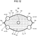
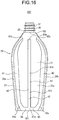
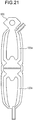
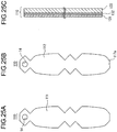
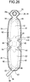
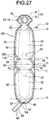
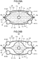
- FIG. 28(a) and FIG. 28(b) are cross sectional views taken along line A-A in FIG. 21 , wherein FIG. 28(b) illustrates a less volume of article remaining in the accommodating area, as compared with the volume illustrated in FIG. 28(a) .
- FIG. 29 is a plan view illustrating a part of the container body-forming sheet member that composes the container body of a sheet container according to Modified Example 10 of the first embodiment.
- Patent Document 1 According to investigations by the present inventors, the design of sheet container described in Patent Document 1 cannot always necessarily reserve a sufficient capacity of sheet container.
- the present invention now relates to a sheet container, a packed article in sheet container, a sheet for container, and a container-forming sheet having a structure capable of ensuring enough capacity.
- the sheet container 100 of this embodiment has a container body 20 that surrounds an accommodating area 20a ( FIG. 12 , etc.) for accommodating an article 96 ( FIG. 12 , etc.).
- the container body 20 is composed of a sheet member (container body-forming sheet member 120) given by lamination of a plurality of film layers (for example, two film layers named a first film layer 121 and a second film layer 122), and a plurality of surface-like parts (for example, four surface-like parts including a first main surface part 21a, a second main surface part 21b, a bottom gusset 23 and a top gusset 22);
- the plurality of surface-like parts include a first surface-like part (for example, first main surface part 21a) and a second surface-like part (for example, bottom gusset 23) that adjoin and cross each other;
- the sheet member has a film region in which the plurality of film layers are attached to each other, and a filler enclosing part [for example
- the intermediate extending part 83 lies continuously over the range from the boundary part 151, towards the end in the extending direction of the intermediate extending part 83.
- the "direction along the boundary part 151" means the direction, which is orthogonal to the direction from the second surface-like part across the boundary part 151 to the first surface-like part. In this embodiment, this nearly coincides the left-right direction in FIG. 2 and FIG. 3 .
- the intermediate extending part 83 extends from the boundary part 151 towards the opposite end 152 (upward in this embodiment), and the film region is formed along the edge on the opposite end 152 side of the intermediate extending part 83 (in this embodiment, upper edge of chevron shape) .
- the intermediate extending part 83 is formed in a convex shape toward the opposite end 152 (convex upward, in this embodiment), and adjoining both sides of the intermediate extending part 83, there are formed film regions which are convex towards the boundary part 151 side (downward, in this embodiment).
- the film regions which are individually adjoining both sides (left and right sides, in this embodiment) of the end in the extending direction of the intermediate extending part 83, are disposed in the ranges including the areas above the first adjoining part 84, and, an area above the second adjoining part 85.
- the container body 20 is given the force which is exerted in the direction of expansion of the boundary part 151 between the first surface-like part and the second surface-like part (that is, the force which drives the first surface-like part and the second surface-like part to align in the same plane).
- the container body 20 will be bulged outward of the container body 20 at the central part of the first surface-like part.
- the container body 20 will have an increased capacity of the inner space, as compared with the container body 20 having no intermediate extending part 83.
- the intermediate extending part 83 extends more further from the second surface-like part than the first adjoining part 84 and the second adjoining part 85 extend, it is possible to sufficiently ensure the bulging of the central part of the first main surface portion 21a.
- the film regions are individually disposed adjoining both sides of the end part of the intermediate extending part 83 in the extending direction thereof, it is possible to sufficiently exert the force of the intermediate extending part 83 trying to flatten even at the end part of the intermediate extending part 83, and thereby the intermediate extending part 83 can more efficiently allow the first main surface part 21a to bulge at the central part.
- the capacity of the sheet container 100 can be sufficiently secured.
- the sheet container 100 of this embodiment is, for example, used as a pump container.
- the present invention is not limited thereto, allowing the sheet container 100 to be used as a squeeze container (a container that discharge the article 96, upon being pressurized).
- a squeeze container a container that discharge the article 96, upon being pressurized.
- the force for pressing the sheet container 100 is transmitted to the container body 20 over a wider area by the intermediate extending part 83, and thereby, making it more easily to press the sheet container 100 and effectively to discharge the article 96.
- the container body 20 demarcates the accommodating area 20a.
- the article 96 is accommodated in the accommodating area 20a, the article 96 is brought into direct contact with the inner surface of the container body 20.
- the sheet container 100 may alternatively have an inner container 10 that is covered with the container body 20, and the accommodating area (accommodating area 10a) may be demarcated by the inner container 10.
- the article 96 accommodated in the accommodating area 10a is brought into direct contact with the inner surface of the inner container 10, but is not brought into direct contact with the inner surface of the container body 20.
- the sheet container 100 is designed in a self-standing form, since the container body 20 has the bottom gusset 23.
- the sheet container is not always necessarily be self-supporting, but may be a form (pillow type) intended for use while being laid down, rather than being stood alone.
- the article 96 is exemplified by shampoo, hair rinse, body soap, detergent, softener, beverage and food.
- the article 96 may be liquid (including paste), or may be solid (for example, particle (including granule), or powder).
- the sheet container 100 has a pumping cap 90, and the article 96 is liquid.
- the article 96 When the article 96 is liquid, the article 96 preferably has a viscosity, for example at 30°C, of equal to or larger than 1 mPa •s and equal to or smaller than 120, 000 mPa ⁇ s (measured using a B-type viscometer, such as Viscometer TV-10 or Viscometer TVB-10 from Toki Sangyo Co., Ltd.), which is more preferably equal to or larger than 1 mPa ⁇ s and equal to or smaller than 60,000 mPa ⁇ s.
- a viscosity for example at 30°C, of equal to or larger than 1 mPa •s and equal to or smaller than 120, 000 mPa ⁇ s (measured using a B-type viscometer, such as Viscometer TV-10 or Viscometer TVB-10 from Toki Sangyo Co., Ltd.
- all of filler enclosing parts (for example, first peripheral enclosing part 41, second peripheral enclosing part 42, specific enclosing part 80, second specific enclosing part 800, filler enclosing part 45, transverse direction enclosing part 46 and filler enclosing part 47) of the sheet container 100 (container body-forming sheet member 120) are formed in a merged manner.
- the container body-forming sheet member 120 may have a plurality of filler enclosing parts independent from each other.
- the sheet container 100 may have a region where the plurality of film layers (for example, the first film layer 121 and the second film layer 122) are kept unattached and have no filler between the plurality of film layers.
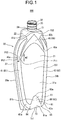
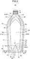
- the front face side of the sheet container 100 and the packed article in sheet container 300 will be referred to as "front”, the rear face side of the sheet container 100 and the packed article in sheet container 300 will be referred to as “rear”, the right side of the sheet container 100 and the packed article in sheet container 300 when viewed from the front face (the right hand side in FIG. 2 and FIG. 11 ) will be referred to as "right”, and the left side of the sheet container 100 and the packed article in sheet container 300 when viewed from the front face (the left hand side in FIG. 2 and FIG. 11 ) will be referred to as "left".
- the container body 20 is formed into the shape as illustrated in FIG. 1 to FIG. 5(b) , by folding the container body-forming sheet member 120 shown in FIG. 7 (a) and FIG. 8 , by attaching the peripheral parts of the container body-forming sheet member 120 to each other, and by enclosing the filler such as air into the non-attached parts 61 to 67 of the container body-forming sheet member 120.
- the mutual attaching of the parts of the container body-forming sheet member 120 is achieved, for example, by heat sealing.
- Such attached region of the peripheral parts of the container body-forming sheet member 120 will be referred to as "sealed part 27".
- the container body 20 has a top gusset 22 which is a gusset formed at the upper end part of the container body 20, a bottom gusset 23 (second surface-like part) which is a gusset formed at the bottom of the container body 20, and a trunk 21 which is a section of the container body 20 located between the top gusset 22 and the bottom gusset 23.
- the top gusset 22 has an opening 24 ( FIG. 1 ) through which the article 96 in the accommodating area 20a may be discharged.
- an opening 24 FIG. 1
- the top gusset 22 for example, there is provided a cylinder part 32 of a spout 30 so as to extend through the opening 24.
- the article 96 in the accommodating area 20a of the container body 20 may be discharged through the spout 30 that extends through the opening 24 of the top gusset 22.
- the container body 20 has an inner space tightly closed except for the opening 24.
- the trunk 21 has a first main surface part 21a (first surface-like part) and a second main surface part 21b (third surface-like part) opposed to each other while placing the accommodating area 20a in between.
- the trunk 21 has a first peripheral part 28a and a second peripheral part 28b, each extending from the top gusset 22 side towards the bottom gusset 23 side, and are arranged side by side. That is, the first peripheral part 28a is a left peripheral part of the trunk 21 (left side marginal part), and the second peripheral part 28b is a right peripheral part of the trunk 21 (right side marginal part).
- the lower marginal part of the first main surface part 21a and the front marginal part of the bottom gusset 23 are mutually connected at the lower end part on the front face side of the container body 20.
- the lower marginal part of the second main surface part 21b and the rear marginal part of the bottom gusset 23 are mutually connected at the lower end part on the rear face side of the container body 20.
- the first main surface part 21a and the second main surface part 21b are mutually connected at the first peripheral part 28a, and also connected at the second peripheral part 28b.
- the level of height of the central part (in this embodiment, a part where the later-described spout 30 is provided) in the transverse direction of the container body 20 is relatively high, and parts on both sides thereof are inclined downward toward the left and right ends of the container body 20.
- the container body 20 has a shape of sloping shoulders.
- the sheet container 100 is capable of self-standing, when the bottom gusset 23 is placed on a horizontal placement face.
- the container body-forming sheet member 120 is preliminarily provided with the spout 30 ( FIG. 8 ), and the cylinder part 32 of the spout 30 is projected out from the opening 24 of the container body 20 ( FIG. 1 , etc.).
- the spout 30 is configured to include a base part 31 with flat plate-like shape attached to the inner surface side of the container body 20, and the cylinder part 32 that projects in one direction out from the base part 31.
- the base part 31 has a through-hole formed at the center thereof, and the inner space of the cylinder part 32 communicates with the through-hole of the base part 31.
- the cylinder part 32 has a cylindrical form. The outer peripheral surface of the cylinder part 32 is threaded, hence the cylinder part 32 constitutes a male thread.
- the accommodating area 20a of the container body 20 can communicate with the outside of the sheet container 100, through the through-hole of the base part 31 of the spout 30, and through the inner space of the cylinder part 32.
- the article 96 in the accommodating area 20a is discharged to the outside, through the spout 30.
- the base part 31 of the spout 30 is fixed by adhesion to the container body-forming sheet member 120 on the surface thereof that composes the inner surface of the container body 20.
- the base part 31 may alternatively be disposed between the first film layer 121 and the second film layer 122 that compose the container body 20, and may be fixed by adhesion to at least one of the first film layer 121 and the second film layer 122.
- the spout 30 of the sheet container 100 has attached thereto the pumping cap 90 illustrated in FIG. 11 .
- the pumping cap 90 has, for example, a cap part 91 that screws with the cylinder part 32 of the spout 30, an upright cylinder 92 that projects upward from the cap part 91, a depressable part 93 that is provided at the top end of the upright cylinder 92 and accepts press down operation by the user, a nozzle 94 that projects nearly horizontally from the depressable part 93, and a liquid feeding tube 95 that communicates with the upright cylinder 92 and projects downward from the cap part 91.
- the container body 20 has an opening 24 through which the article 96 can be discharged
- the sheet container 100 has the pumping cap 90 that is attached to the marginal part of the opening 24 of the container body 20
- the pumping cap 90 has an operation part (depressable part 93) which accepts the pushing operation, and can discharges the article 96 to the outside by the pushing operation on the operation part.
- the pumping cap 90 is attachable to and detachable from the cylinder part 32. After the article 96 in the sheet container 100 was fully consumed, the pumping cap 90 may be attached to a new sheet container 100 that contains the article 96 (packed article in sheet container 300), and may be used just like before. That is, while the sheet container 100 that contains the article 96 (packed article in sheet container 300) might be disposable, the pumping cap 90 may be recycled.
- the container body 20 has, for example, filler enclosing parts individually described below, that is, the first peripheral enclosing part 41, the second peripheral enclosing part 42, the specific enclosing part 80 (the specific enclosing part 80 includes the intermediate extending part 83, the first adjoining part 84, and the second adjoining part 85), the second specific enclosing part 800 (the second specific enclosing part 800 includes the second intermediate extending part 830, the first adjoining part 84, and the second adjoining part 85), the filler enclosing part 45, the transverse direction enclosing part 46, and the filler enclosing part 47.
- the first peripheral enclosing part 41, the second peripheral enclosing part 42, the specific enclosing part 80 includes the intermediate extending part 83, the first adjoining part 84, and the second adjoining part 85
- the second specific enclosing part 800 includes the second intermediate extending part 830, the first adjoin
- the first peripheral enclosing part 41 extends vertically along the left peripheral part of the trunk 21, that is, the first peripheral part 28a.
- the container body 20 has a pair of front and rear, first peripheral enclosing parts 41. That is, the first peripheral enclosing parts 41 are individually formed in each of the first main surface part 21a and the second main surface part 21b.
- the second peripheral enclosing part 42 extends vertically along the right peripheral part of the trunk 21, that is, the second peripheral part 28b.
- the container body 20 has a pair of front and rear, second peripheral enclosing parts 42. That is, the second peripheral enclosing parts 42 are individually formed in each of the first main surface part 21a and the second main surface part 21b.
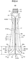
- a lower part 41a of the front first peripheral enclosing part 41 is arranged in an inclined posture so that, for example, it shifts rightward as it goes down.
- a lower part 42a of the front second peripheral enclosing part 42 is arranged in an inclined posture so that, for example, it shifts leftward as it goes down.
- a lower part 41a of the rear first peripheral enclosing part 41 is arranged in an inclined posture so that, for example, it shifts rightward as it goes down
- a lower part 42a of the rear second peripheral enclosing part 42 is arranged in an inclined posture so that, for example, it shifts leftward as it goes down
- FIG. 3 is a rear view, and is therefore the right and left are reversed from FIG. 2 ).
- the specific enclosing part 80 includes the intermediate extending part 83, the first adjoining part 84 and the second adjoining part 85.
- the intermediate extending part 83 is disposed across the first main surface part 21a and the bottom gusset 23.
- each of the first adjoining part 84 and the second adjoining part 85 is disposed across the first main surface part 21a and the bottom gusset 23.
- the specific enclosing part 80 is formed, for example, laterally symmetrical.
- the second specific enclosing part 800 is formed symmetrically about the specific enclosing part 80 in the front-rear direction.
- the second specific enclosing part 800 has the second intermediate extending part 830 that is symmetrical about the intermediate extending part 83 in the front-rear direction, and a first adjoining part 84 and a second adjoining part 85 that are symmetrical about the first adjoining part 84 and the second adjoining part 85 of the specific enclosing part 80 in the front-rear direction.
- the second intermediate extending part 830 is disposed across the second main surface part 21b and the bottom gusset 23.
- each of the first adjoining part 84 and the second adjoining part 85 of the second intermediate extending part 830 is disposed across the second main surface part 21b and the bottom gusset 23.
- the second specific enclosing part 800 is formed, for example, laterally symmetrical.
- the intermediate extending part 83 of the specific enclosing part 80 extends more further from the bottom gusset 23 than the first adjoining part 84 and the second adjoining part 85 of the specific enclosing part 80 extend. That is, height H1 given in FIG. 2 is larger than heights H2, H3.
- Height H1 given in FIG. 2 represents the height from the bottom gusset 23 to the end 83a (i.e., upper end part) on the opposite end 152 side of the intermediate extending part 83. In other words, this is the height from a placement face to the end 83a when the sheet container 100 stands alone.
- Heights H2, H3 given in FIG. 2 represent the heights from the bottom gusset 23 to the upper end parts of the first adjoining part 84 and the second adjoining part 85 of the specific enclosing part 80.
- the second intermediate extending part 830 of the second specific enclosing part 800 extends more further from the bottom gusset 23 than the first adjoining part 84 and the second adjoining part 85 of the second specific enclosing part 800 extends. That is, the height H1 given in FIG. 3 is larger than heights H2, H3.
- Height H1 given in FIG. 3 represents the height from the bottom gusset 23 to the end 830a (i.e., upper end part) on the opposite end 152 side of the second intermediate extending part 830. In other words, this is the height from the placement face to the end 830a when the sheet container 100 stands alone.
- Heights H2, H3 given in FIG. 3 represent the heights from the bottom gusset 23 to the upper end parts of the first adjoining part 84 and the second adjoining part 85 of the second specific enclosing part 800.
- a part of the specific enclosing part 80, which is disposed in the first main surface part 21a, will be referred to as a first part 81, meanwhile a part of the specific enclosing part 80, which is disposed in the bottom gusset 23, will be referred to as a second part 82.
- a part of the second specific enclosing part 800, which is disposed in the second main surface part 21b, will be referred to as the first part 81, meanwhile a part of the second specific enclosing part 800, which is disposed in the bottom gusset 23, will be referred to as the second part 82.
- the first part 81 of the specific enclosing part 80 includes a base part 81a that is horizontally disposed along the boundary part 151 between the first main surface part 21a and the bottom gusset 23, and laid across the first adjoining part 84, the intermediate extending part 83 and the second adjoining part 85; and a projection part 81b which is a part of the intermediate extending part 83, and protrudes out from the base part 81a and away from the bottom gusset 23 (that is, projects upward out from the base part 81a).
- the left end of the base part 81a of the specific enclosing part 80 (left end of the first adjoining part 84) is connected to the lower end part of the first peripheral enclosing part 41 on the front side, meanwhile the right end of the base part 81a of the specific enclosing part 80 (right end of the second adjoining part 85) is connected to the lower end part of the second peripheral enclosing part 42 on the front side.
- the first peripheral enclosing part 41 on the front side and the second peripheral enclosing part 42 on the front side communicate with each other, while placing the base part 81a of the first part 81 of the specific enclosing part 80 in between.
- the first part 81 of the second specific enclosing part 800 includes a base part 81a that is horizontally disposed along the boundary part 151 between the second main surface part 21b and the bottom gusset 23, and laid across the first adjoining part 84, the intermediate extending part 830 and the second adjoining part 85; and a projection part 81b which is a part of the second intermediate extending part 830, and protrudes out from the base part 81a and away from the bottom gusset 23 (that is, projects upward out from the base part 81a).
- the left end of the base part 81a of the second specific enclosing part 800 (left end of the first adjoining part 84) is connected to the lower end part of the first peripheral enclosing part 41 on the rear side, meanwhile the right end of the base part 81a of the second specific enclosing part 800 (right end of the second adjoining part 85) is connected to the lower end part of the second peripheral enclosing part 42 on the rear side.
- the first peripheral enclosing part 41 on the rear side and the second peripheral enclosing part 42 on the rear side communicate with each other, while placing the base part 81a of the first part 81 of the second specific enclosing part 800 in between.
- the container body 20 Since the container body 20 is designed to have the intermediate extending part 83 laid across the first surface-like part and the second surface-like part, the container body 20 is given the force which is exerted in the direction of expansion of the boundary part 151 between the first surface-like part and the second surface-like part (that is, the force which drives the first surface-like part and the second surface-like part to align in the same plane), by the force of the intermediate extending part 83 trying to flatten. In this way, the container body 20 will be bulged outward of the container body 20 at the central part of the first surface-like part. Hence, the container body 20 will have an increased capacity of the inner space, as compared with the container body 20 having no intermediate extending part 83.
- the intermediate extending part 83 extends more further from the second surface-like part than the first adjoining part 84 and the second adjoining part 85 extend, it is possible to sufficiently ensure the bulging of the central part of the first main surface portion 21a.
- the intermediate extending part 83 can more efficiently allow the first main surface part 21a to bulge at the central part.
- the capacity of the sheet container 100 can be sufficiently secured.
- the container body 20 is designed to have the second intermediate extending part 830 laid across the first surface-like part and the third surface-like part, the container body 20 is given the force which is exerted in the direction of expansion of the boundary part 151 between the third surface-like part and the second surface-like part (that is, the force which drives the third surface-like part and the second surface-like part to align in the same plane), by the force of the second intermediate extending part 830 trying to flatten. In this way, the container body 20 will be bulged outward of the container body 20 at the central part of the third surface-like part. Hence, the container body 20 will have an increased capacity of the inner space, as compared with the container body 20 having no second intermediate extending part 830.
- the second intermediate extending part 830 extends more further from the second surface-like part than the first adjoining part 84 and the second adjoining part 85 extend, it is possible to sufficiently ensure the bulging of the central part of the second main surface portion 21b.
- the second intermediate extending part 830 can more efficiently allow the second main surface part 21b to bulge at the central part.
- the capacity of the sheet container 100 can be sufficiently secured.
- the plurality of surface-like parts include the third surface-like part (second main surface part 21b) which is opposed to the first surface-like part (first main surface part 21a) while placing the accommodating area 20a in between;
- the container body 20 has a trunk 21 that includes the first surface-like part and the third surface-like part, and the bottom (bottom gusset part 23) composed of the second surface-like part;
- the trunk 21 has the first peripheral part 28a and the second peripheral part 28b, each extending from the boundary part 151 side towards the opposite end 152 side, and being arranged side by side;
- the first surface-like part and the third surface-like part are mutually connected at each of the first peripheral part 28a and the second peripheral part 28b;
- a portion of the filler enclosing part, located in the first surface-like part is preferably formed symmetrically (in this embodiment, symmetrically in the front-rear direction) about a portion of the filler enclosing part located in the third surface-like part; a portion
- the capacity of the sheet container 100 can be sufficiently secured.
- the first peripheral enclosing part 41 and the second peripheral enclosing part 42 on the front side extend towards the opposite end 152 side, more further than the intermediate extending part 83 extends.
- the first surface-like part (first main surface part 21a) has the first peripheral part 28a and the second peripheral part 28b, each extending from the boundary part 151 side towards the opposite end 152 side, and being arranged side by side;
- the first adjoining part 84 is disposed between the intermediate extending part 83 and the first peripheral part 28a;
- the second adjoining part 85 is disposed between the intermediate stretched 83 part and the second peripheral part 28b;
- the filler enclosing part comprises: a first peripheral enclosing part 41 that extends from one end on the first peripheral part 28a side of the first adjoining part 84 towards the opposite end 152, along the first peripheral part 28a; and a second peripheral enclosing part 42 that extends from one end on the second peripheral part 28b side of the second adjoining part 85 towards the opposite end 152, along the second peripheral part 28b; and, the shortest distance from the opposite end 152 to the end 83a of the intermediate extending part 83 on the opposite end 152 side is longer than
- first peripheral enclosing part 41 and the second peripheral enclosing part 42 on the rear side extend towards the opposite end 152 side, more further than the second intermediate extending part 830 extends.
- the transverse width of the projection part 81b is maximized at the lower end part of the projection part 81b.
- a portion (first part 81) of the filler enclosing part which falls on the first surface-like part (first main surface part 21a), has a base part 81a that is disposed along the boundary part 151, and laid across the first adjoining part 84, the intermediate extending part 83 and the second adjoining part 85; and a projection part 81b, which is a part of the intermediate extending part 83, and protrudes out from the base part 81a and away from the boundary part 151; and, the width dimension of the projection part 81b in the direction parallel to the boundary part 151 is maximized at the end part on the base part 81a side of the projection part 81b.
- the projection part 81b is formed into a chevron shape with the transverse width made narrower as being farther from the base part 81a.
- the projection part 81b is formed into a chevron shape in which the width dimension of the projection part 81b in the direction parallel to the boundary part 151 becomes narrower as being farther from the base part 81a.
- the upper end part of the projection part 81b is rounded, for example.
- the distance, from the bottom gusset 23 to the end 83a of the intermediate extending part 83 in the extending direction of the intermediate extending part 83, is equal to or less than a half of the distance from the bottom gusset 23 to the opposite end 152. That is, the height of the first part 81 is equal to or less than a half of the height of the first main surface part 21a.
- the distance, from the bottom gusset 23 to the end 830a of the second intermediate extending part 830 in the extending direction of the second intermediate extending part 830, is equal to or less than a half of the distance from the bottom gusset 23 to the opposite end 152.
- the transverse direction enclosing part 46 is disposed at the central part of the trunk 21 in the transverse direction, in an upper part of the trunk 21.
- the container body 20 has a pair of front and rear transverse direction enclosing parts 46. That is, the transverse direction enclosing part 46 are individually formed in each of the first main surface part 21a and the second main surface part 21b.
- the front transverse direction enclosing part 46 is disposed in a region of the first main surface part 21a on the opposite end 152 side thereof (that is, an upper part of the first main surface part 21a), and extends from the first peripheral part 28a towards the second peripheral part 28b (that is, in the transverse direction) .
- the rear transverse direction enclosing part 46 is disposed in a region of the second main surface part 21b on the opposite end 152 side thereof (that is, an upper part of the second main surface part 21b), and extends from the first peripheral part 28a towards the second peripheral part 28b.
- each transverse direction enclosing part 46 is connected to the upper part of the first peripheral enclosing part 41, and the right end of each transverse direction enclosing part 46 is connected to the upper part of the second peripheral enclosing part 42.
- the front first peripheral enclosing part 41 communicates with the front second peripheral enclosing part 42 through the front transverse direction enclosing part 46
- the rear first peripheral enclosing part 41 communicates with the rear second peripheral enclosing part 42 through the rear transverse direction enclosing part 46.
- connection part 46a crossing part of the first peripheral enclosing part 41 and the transverse direction enclosing part 46
- the transverse direction enclosing part 46 is thinner than the first peripheral enclosing part 41. That is, width w2 given in FIG. 1 is smaller than width w2.
- point P11 given in FIG. 1 represents a corner on the inner lane side of the connection part 46a (crossing part) between the first peripheral enclosing part 41 and the transverse direction enclosing part 46.
- Width w1 represents a minimum width (distance between point P11 and point P12) of the first peripheral enclosing part 41 originated from point P11
- width w2 is a minimum width (distance between point P11 and point P13) of the transverse direction enclosing part 46 originated from point P11.
- width w1 is given by a minimum width of the first peripheral enclosing part 41 in the vicinity of the connection part 46a
- width w2 is given by a minimum width of the transverse direction enclosing part 46 in the vicinity of the connection part 46a.
- connection part 46a crossing part of the second peripheral enclosing part 42 and the transverse direction enclosing part 46
- the transverse direction enclosing part 46 is thinner than the second peripheral enclosing part 42.
- the first surface-like part (first main surface part 21a) has the first peripheral part 28a and the second peripheral part 28b, each extending from the boundary part 151 side towards the opposite end 152 side, and being arranged side by side;
- the first adjoining part 84 is disposed between the intermediate extending part 83 and the first peripheral part 28a;
- the second adjoining part 85 is disposed between the intermediate extending part 83 part and the second peripheral part 28b;
- the filler enclosing part comprises: a first peripheral enclosing part 41 that extends from one end on the first peripheral part 28a side of the first adjoining part 84 towards the opposite end 152, along the first peripheral part 28a; and a second peripheral enclosing part 42 that extends from one end on the second peripheral part 28b side of the second adjoining part 85 towards the opposite end 152, along the second peripheral part 28b; and the transverse direction enclosing part 46 that extends, in a region of the first surface-like part on the opposite end 152 side
- the transverse direction enclosing part 46 is thinner than the second peripheral enclosing part 42, in the connection part 46a between the second peripheral enclosing part 42 and the transverse direction enclosing part 46.
- the transverse direction enclosing part 46 is thinner than the first peripheral enclosing part 41, in the connection part 46a between the first peripheral enclosing part 41 and the transverse direction enclosing part 46; and, the transverse direction enclosing part 46 is thinner than the second peripheral enclosing part 42, in the connection part 46a between the second peripheral enclosing part 42 and the transverse direction enclosing part 46.
- the transverse direction enclosing part 46 is, for example, formed into an inverted V-shape whose height position is highest at the central part thereof in the transverse direction, and is lower at both lateral ends thereof. In short, each of the upper edge and the lower edge of the transverse direction enclosing part 46 is convex upward.
- an edge part on the opposite end 152 side of the projection part 81b has a convex shape toward the opposite end 152 side
- the transverse direction enclosing part 46 has a convex curved shape toward the opposite end 152 side.
- Each of the first peripheral enclosing part 41 and the second peripheral enclosing part 42 extends, for example, above the connection part 46a of the first peripheral enclosing part 41 or the second peripheral enclosing part 42, with the transverse direction enclosing part 46.
- the filler enclosing part 45 is disposed across the bottom gusset 23 and the trunk 21.
- a part of the filler enclosing part 45, disposed on the trunk 21 side, will be referred to as a first part 451, meanwhile a part thereof disposed on the bottom gusset 23 will be referred to as a second part 452.
- the container body 20 has a pair of left and right filler enclosing parts 45.
- the left filler enclosing part 45 is disposed between the lower part 41a of the front first peripheral enclosing part 41, and lower part 41a of the rear first peripheral enclosing part 41.
- the right filler enclosing part 45 is disposed between the lower part 42a of the front second peripheral enclosing part 42, and the lower part 42a of the rear second peripheral enclosing part 42 ( FIG. 4 ) .
- Each filler enclosing part 45 has, for example, a chevron shape whose degree of protrusion becomes larger towards the center in the front-rear direction.
- the lower end part of the left filler enclosing part 45 is connected to each of the left end of the lower end part of the specific enclosing part 80, and the left end of the lower end part of the second specific enclosing part 800.
- the lower end part of the right filler enclosing part 45 is connected to each of the right end of the lower end part of the specific enclosing part 80, and the right end of the lower end part of the second specific enclosing part 800.
- the specific enclosing part 80 communicates with the second specific enclosing part 800, through the left filler enclosing part 45, and also through the right filler enclosing part 45.
- the bottom gusset 23 is formed into a shape (for example, near rectangular shape) having a first bottom peripheral part 231, a second bottom peripheral part 232 opposed to the first bottom peripheral part 231, a third bottom peripheral part 233 disposed between one end of the first bottom peripheral part 231 and one end of the second bottom peripheral part 232, and a fourth bottom peripheral part 234 opposed to the third bottom peripheral part 233.
- the intermediate extending part 83 is disposed across the first bottom peripheral part 231 and the trunk 21, the second intermediate extending part 830 is disposed across the second bottom peripheral part 232 and the trunk 21, the one filler enclosing part 45 is disposed across the third bottom peripheral part 233 and the trunk 21, and the other filler enclosing part 45 is disposed across the fourth bottom peripheral part 234 and the trunk 21.
- the pair of left and right filler enclosing parts 45 are opposed to each other while placing the lower end part of the accommodating area 20a in between.
- the bottom gusset 23 includes a bulge 23a (see FIG. 5(b) ) having a raised shape convex upward.
- the plurality of surface-like parts of the container body 20 include the third surface-like part (second main surface part 21b) which is opposed to the first surface-like part (first main surface part 21a) while placing the accommodating area 20a in between;
- the container body 20 has the trunk 21 that includes the first surface-like part and the third surface-like part, and the bottom (bottom gusset part 23) composed of the second surface-like part;
- the trunk 21 has the first peripheral part 28a and the second peripheral part 28b, each extending from the boundary part 151 side towards the opposite end 152 side, and being arranged side by side;
- the first surface-like part and the third surface-like part are mutually connected at each of the first peripheral part 28a and the second peripheral part 28b;
- the bottom is formed into the shape having the first bottom peripheral part 231, the second bottom peripheral part 232 opposed to the first bottom peripheral part 231, the third bottom peripheral part 233 disposed between one end of the first bottom peripheral part 231 and one end of the second bottom peripheral part 232, and the fourth bottom
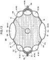
- the force is applied to four portions, adjoining the bottom (bottom gusset 23), of the trunk 21 so as to expand each portion outwardly, and thereby the capacity of the container body 20 can be more sufficiently secured (see FIG. 13 , FIG. 14 and FIG. 15 ).
- An aggregate of the second part 82 of the specific enclosing part 80 falling on the bottom gusset 23, the second part 82 of the second specific enclosing part 800 falling on the bottom gusset 23, and the second parts 452 of the left and right filler enclosing parts 45 falling on the bottom gusset 23, are arranged annularly, as illustrated in FIG. 5(b) , along the circumference the bottom gusset 23.
- the filler enclosing part 47 is, for example, connected to the upper part of the rear transverse direction enclosing part 46, and extends from the transverse direction enclosing part 46 towards the outer edge of the second main surface part 21b.
- all filler enclosing parts owned by the sheet container 100 communicate with each other.
- the filler enclosing part is sealed at a closure part 26 ( FIG. 5(a) ) that adjoins the end part of the filler enclosing part 47.
- the filler may be fluid (gas or liquid), solid (for example, particulate, resin pellet, etc.) or semi-solid (for example, foam material, etc.), and is preferably a gas such as air.
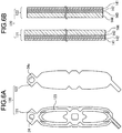
- the first film layer 121 is a film layer that composes the outer surface side of the container body 20. As illustrated in FIG. 6(b) , the first film layer 121 is formed by laminating, for example, a first layer 141, a second layer 142, a third layer 143 and a fourth layer 144 in this order.
- the first layer 141 is made, for example, of polyethylene terephthalate (PET) or oriented nylon (ONy).
- PET polyethylene terephthalate
- ONy oriented nylon
- the second layer 142 is, for example, a transparent evaporated PET layer made of polyethylene terephthalate, with silica and alumina vapor-deposited on one surface thereof (the surface on the side of the first layer 141).
- the third layer 143 is, for example, made of oriented nylon.
- the fourth layer 144 is, for example, made of linear low-density polyethylene (LLDPE).
- LLDPE linear low-density polyethylene
- the first layer 141 may be 12 ⁇ m thick
- the second layer 142 may be 12 ⁇ m thick
- the third layer 143 may be 15 ⁇ m thick
- the fourth layer 144 may be 40 ⁇ m, for example.
- Major function of the first layer 141 is exemplified by provision of glossiness and printability of the container body 20, as well as provision of rigidity of the container body 20.
- Major function of the second layer 142 is exemplified by provision of gas barrier performance.
- Major function of the third layer 143 is exemplified by provision of pinhole resistance.
- Major function of the fourth layer 144 is exemplified by provision of heat sealability with the second film layer 122, and heat sealability between the parts of the first film layers 121.
- the second film layer 122 is a film layer that composes the inner surface side of the container body 20.
- the layer structure employable in the second film layer 122 may be same as that in the first film layer 121.
- materials for composing the first film layer 121 and the second film layer 122 are not limited to those exemplified above.
- the second film layer 122 may have a layer structure different from that in the first film layer 121.
- a linear low-density polyethylene (LLDPE) layer same as that composing the fourth layer 144, may be provided as the outermost first layer 141.
- LLDPE linear low-density polyethylene
- the parts of the second film layers 122 may be heat-sealed at the sealed part 27.
- a container body-forming sheet member 120 is formed by stacking the first film layer 121 and the second film layer 122, and then attaching them to each other (for example, by heat sealing).
- the first film layer 121 and the second film layer 122 are stacked, so that the fourth layer 144 of the first film layer 121 is faced to the fourth layer 144 of the second film layer 122. While keeping this arrangement, the first film layer 121 and the second film layer 122 are mutually pressurized and heated, whereby the fourth layer 144 of the first film layer 121 and the fourth layer 144 of the second film layer 122 are heat-sealed to each other.
- the container body-forming sheet member 120 is formed in this way (see FIG. 7 (a), FIG. 7(b) ).
- a non-attaching part 123 ( FIG. 6(a) ) having been subjected to non-attaching treatment is formed on the surface(s) facing the other, so as to the first film layer 121 and the second film layer 122 (the fourth layer 144 of the first film layer 121 and the fourth layer 144 of the second film layer 122) will left partially unattached to each other, and thereby, the non-attached parts 61, 62, 63, 65, 66, 67, and 68 will be formed as illustrated in FIG. 7(a) .
- the non-attaching part 123 may easily be formed by coating a non-attaching agent (adhesion inhibitor) to a corresponded part and setting it in an adhesion inhibited state.
- the adhesion inhibitor may freely be selectable from those capable of inhibiting attaching between the first film layer 121 and the second film layer 122.
- the adhesion inhibitor suitably employable are printing inks used for offset printing, flexographic printing and letterpress printing; medium ink; and dedicated adhesion inhibition ink. Also thermosetting or UV-curable ink may suitably be used.
- non-attaching part 123 Area of formation of the non-attaching part 123 will be the non-attached parts (non-attached parts 61, 62, 63, 65, 66, 67, 68).
- each non-attached part 61 corresponds to the each first peripheral enclosing part 41
- each non-attached part 62 corresponds to each second peripheral enclosing part 42
- one non-attached part 63 corresponds to the specific enclosing part 80
- the other non-attached part 63 corresponds to the second specific enclosing part 800
- each non-attached part 65 corresponds to each filler enclosing part 45
- each non-attached part 66 corresponds to each transverse direction enclosing part 46
- the non-attached part 67 corresponds to the filler enclosing part 47.
- the non-attached part 68 will serve as an introducing part through which the filler is introduced into each of the non-attached parts.
- the one non-attached part 63 has an intermediate extending part-forming part 630 that corresponds to the intermediate extending part 83, a first adjoining part-forming part 631 that corresponds to the first adjoining part 84, and a second adjoining part-forming part 632 that corresponds to the second adjoining part 85.
- the other non-attached part 63 is composed in the same way as the one non-attached part 63, and has an intermediate extending part-forming part that corresponds to the second intermediate extending part 830, a first adjoining part-forming part that corresponds to the first adjoining part 84, and a second adjoining part-forming part that corresponds to the second adjoining part 85.
- the first film layer 121 and the second film layer 122 are then attached at the boundary part between the non-attached part 68 and the non-attached part 67, thereby, the closure part 26, as well as each of the filler enclosing parts (first peripheral enclosing part 41, second peripheral enclosing part 42, specific enclosing part 80, second specific enclosing part 800, filler enclosing part 45, transverse direction enclosing part 46, filler enclosing part 47) are formed.
- Method for forming the non-attached parts 61, 62, 63, 65, 66, 67, 68 between the first film layer 121 and the second film layer 122 is not limited to the method exemplified above.
- a die used for heat sealing of the first film layer 121 and the second film layer 122 may have formed therein a recess (groove) in an area corresponded to the non-attached parts 61, 62, 63, 65, 66, 67, 68.
- the first film layer 121 and the second film layer 122 may be heat-sealed, while placing therebetween a spacer layer composed of a non-heat sealable material (for example, resin layer such as PET layer).
- the first film layer 121 is formed slightly larger than the second film layer 122, and protrudes around the periphery of the second film layer 122.
- the fourth layer 144 of the first film layer 121 exposes.
- the opening 24 In a part of the first film layer 121 used for composing the top gusset 22, there is formed the opening 24 through which the cylinder part 32 of the spout 30 is inserted ( FIG. 6(a) ). Meanwhile, in a part of the second film layer 122 used for composing the top gusset 22, there is formed the opening 24a which is slightly larger than the opening 24 ( FIG. 6(a) ). Hence, the fourth layer 144 of the first film layer 121 exposes around the circumference of the opening 24, and, inside of the opening 24a (see FIG. 7(a) ).
- a container-forming sheet 400 is formed by providing the spout 30 to the container body-forming sheet member 120.
- the base part 31 of the spout 30 is fixed to the fourth layer 144 of the first film layer 121 of the container body-forming sheet member 120, at around the opening 24 and to the inner part of the opening 24a.
- the container-forming sheet 400 includes a first main surface sheet part 51, a second main surface sheet part 52, a first bottom gusset sheet part 53, a second bottom gusset sheet part 54 and a top gusset sheet part 55, which will be explained in turn below.
- the first main surface sheet part 51 composes the first main surface part 21a.
- the first main surface sheet part 51 includes a top gusset attaching part 56.
- the second main surface sheet part 52 composes the second main surface part 21b.
- the second main surface sheet part 52 includes a top gusset attaching part 57.
- the first bottom gusset sheet part 53 and the second bottom gusset sheet part 54 compose the bottom gusset 23 of the container body 20.
- the top gusset sheet part 55 composes the bottom gusset 23 of the container body 20.
- the top gusset sheet part 55 is formed, for example, into a hexagonal shape (in more detail, a laterally oblong hexagonal shape).
- the first main surface sheet part 51 shares one side with the top gusset sheet part 55, and is connected to the lower side of the top gusset sheet part 55 in FIG. 8 .
- the top gusset attaching part 56 is formed, for example, into a trapezoidal shape with the upper base shorter than the lower base.
- a part of the first main surface sheet part 51, located below an area along the folding line 74, is formed for example in a vertically oblong rectangular shape.
- the first bottom gusset sheet part 53 is a part which composes the bottom gusset 23, together with the second bottom gusset sheet part 54.
- the first bottom gusset sheet part 53 and the second bottom gusset sheet part 54 have the same shape.
- Each of the first bottom gusset sheet part 53 and the second bottom gusset sheet part 54 has, for example, a laterally oblong rectangular shape.
- the transverse width of the first bottom gusset sheet part 53 and the second bottom gusset sheet part 54 is set equivalent to the transverse width of the lower end part of the first main surface sheet part 51.
- the first bottom gusset sheet part 53 is connected to the lower side of the first main surface sheet part 51, meanwhile the second bottom gusset sheet part 54 is connected to the lower side of the first bottom gusset sheet part 53.
- the second main surface sheet part 52 is connected to the lower side of the second bottom gusset sheet part 54.
- the second main surface sheet part 52 is formed into a shape same as the first main surface sheet part 51.
- the second main surface sheet part 52 is provided integrally with a filler introducing part 29.
- the filler introducing part 29 has formed therein the non-attached part 68 that reaches the outer edge of the filler introducing part 29.
- the non-attached part 68 communicates with the non-attached part 67.
- the first film layer 121 and the second film layer 122 have the same size, so that the first film layer 121 is not protruded around the periphery of the second film layer 122. In other words, in the filler introducing part 29, the fourth layer 144 of the first film layer 121 is not exposed.
- the base part 31 of the spout 30 is located on this side of the top gusset sheet part 55, and the cylinder part 32 projects through the top gusset sheet part 55 and comes out therefrom, towards the far side.
- the base part 31 may alternatively be disposed between the first film layer 121 and the second film layer 122.
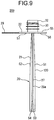
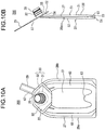
- the sheet for container 200 ( FIG. 9 , FIG. 10(a), FIG. 10(b) ) is formed by folding the container-forming sheet 400, and by attaching (by heat-sealing, for example) the peripheral parts of the container body-forming sheet member 120 to each other.
- the container-forming sheet 400 is heat sealed to form the sheet for container 200, while being valley-folded along two folding lines 71 and one folding line 72 illustrated in FIG. 8 , and mountain-folded at a folding line 73 and two folding lines 74.
- the valley folding means a way of folding making the sheet convex towards the far side in FIG. 8
- the mountain folding means a way of folding making the sheet convex towards this side in FIG. 8 .
- One of the two folding lines 71 lies on the boundary between the first main surface sheet part 51 and the first bottom gusset sheet part 53, and the other lies on the boundary between the second main surface sheet part 52 and the second bottom gusset sheet part 54.
- the folding line 72 lies on the boundary between the top gusset sheet part 55 and the first main surface sheet part 51 (the boundary between the top gusset sheet part 55 and the top gusset attaching part 56).
- the folding line 73 lies on the boundary between the first bottom gusset sheet part 53 and the second bottom gusset sheet part 54.
- One of the two folding lines 74 lies on the boundary between the top gusset attaching part 56 of the first main surface sheet part 51 and the other part of the first main surface sheet part 51, meanwhile, the other one lies on the boundary between the top gusset attaching part 57 of the second main surface sheet part 52 and the other part of the second main surface sheet part 52.
- the top gusset attaching part 57 overlap with each other; the first bottom gusset sheet part 53 and the second bottom gusset sheet part 54 overlap with each other; the first bottom gusset sheet part 53 and the lower end part of the first main surface sheet part 51 overlap with each other; the second bottom gusset sheet part 54 and the lower end part of the second main surface sheet part 52 overlap with each other; and, a part of the first main surface sheet part 51 excluding the top gusset attaching part 56, and a part of the second main surface sheet part 52 excluding the top gusset attaching part 57 overlap with each other.
- the half part of the top gusset sheet part 55 (the lower half as shown in FIG. 8 ) and the top gusset attaching part 56 are attached to each other; the other part of the top gusset sheet part 55 (the upper half as shown in FIG. 8 ) and the top gusset attaching part 57 are attached to each other; the first bottom gusset sheet part 53 and the lower end part of the first main surface sheet part 51 are attached to each other; the second bottom gusset sheet part 54 and the lower end part of the second main surface sheet part 52 are attached to each other; and, the first main surface sheet part 51 and the second main surface sheet part 52 are attached to each other.
- the part attached to the second main surface sheet part 52 in the first main surface sheet part 51 is, the part excluding the top gusset attaching part 56 and a part of the first main surface sheet part 51 which overlaps the first bottom gusset sheet part 53.
- the part attached to the first main surface sheet part 51 in the second main surface sheet part 52 is, the part excluding the top gusset attaching part 57 and a part of the second main surface sheet part 52 which overlaps the second bottom gusset sheet part 54.
- each of first bottom gusset sheet part 53 and the second bottom gusset sheet part 54 has notched parts 58 formed on the left and right ends thereof.
- the sheet for container 200 has the tubular filler introducing part 29 that projects out from the container body 20.
- the non-attached part 68 of the filler introducing part 29 serves as an introducing part through which the filler is introduced into spaces within each of the non-attached parts 61, 62, 63, 65, 66 and 67.
- Location of the filler introducing part 29 is not specifically limited. In this embodiment, for example, the filler introducing part 29 is disposed so that the filler introducing part 29 protrudes from one end of the non-attached part 67.
- FIG. 9 illustrates the top gusset 22 (and the top gusset 12, not illustrated) laid orthogonally to the trunk 21 (and the trunk 11, not illustrated).
- the container-forming sheet 400 When the container-forming sheet 400 is heat-sealed, the sheet will be held as illustrated in FIG. 9 , with the half part of the top gusset sheet part 55 and the top gusset attaching part 56 held by dies (not illustrated), with the other part of the top gusset sheet part 55 and the top gusset attaching part 57 held by the dies, and, also with the first main surface sheet part 51, the second main surface sheet part 52, the first bottom gusset sheet part 53 and the second bottom gusset sheet part 54 held by the dies.
- FIG. 10 (a) and FIG. 10 (b) illustrate a state in which the sheet for container 200 is bent so that the top gusset attaching part 56 is overlapped with the other part of the first main surface sheet part 51.
- the sheet for container 200 kept in the thus-bent state is fed from a process for manufacturing the sheet for container 200, to a process for enclosing the article 96 into the accommodating area 20a of the container body 20.
- the filler air, for example
- the filler is introduced through the non-attached part 68 of the filler introducing part 29, into each of the non-attached parts 61, 62, 63, 65, 66 and 67.
- each of the non-attached parts 61, 62, 63, 65, 66 and 67 is expanded to form the first peripheral enclosing part 41, the second peripheral enclosing part 42, the specific enclosing part 80, the second specific enclosing part 800, the filler enclosing part 45, the transverse direction enclosing part 46, and the filler enclosing part 47, thereby adding rigidity to the container body 20.
- the filler is enclosed between the first film layer 121 and the second film layer 122 in each of the non-attached parts 61, 62, 63, 65, 66 and 67, and thereby the first peripheral enclosing part 41, the second peripheral enclosing part 42, the specific enclosing part 80, the second specific enclosing part 800, the filler enclosing part 45, the transverse direction enclosing part 46, and the filler enclosing part 47 are formed.
- the trunk 21 bulges also in the front-rear direction.
- the filler enclosing parts (the first peripheral enclosing part 41, the second peripheral enclosing part 42, the specific enclosing part 80, the second specific enclosing part 800, the filler enclosing part 45, the transverse direction enclosing part 46, the filler enclosing part 47) are formed, for example, a part of the filler enclosing part 47 adjoining the non-attached part 68 is suitably sealed (that is, the first peripheral enclosing part 41, the second peripheral enclosing part 42, the specific enclosing part 80, the second specific enclosing part 800, the filler enclosing part 45, the transverse direction enclosing part 46, and the filler enclosing part 47 are sealed, and the filler is enclosed in each of the first peripheral enclosing part 41, the second peripheral enclosing part 42, the specific enclosing part 80, the second specific enclos
- the filler is prevented from leaking from each of the first peripheral enclosing part 41, the second peripheral enclosing part 42, the specific enclosing part 80, the second specific enclosing part 800, the filler enclosing part 45, the transverse direction enclosing part 46, and the filler enclosing part 47.
- the filler introducing part 29 is cut off at the base part.
- the sheet container 100 is thus manufactured.
- the sheet for container 200 includes the container body 20 that surrounds the accommodating area 20a for accommodating the article 96; the container body is composed of the sheet member given by lamination of the plurality of film layers (container body-forming sheet member 120); the sheet member has the film region in which the plurality of film layers are attached to each other, and the non-attached region (non-attached parts 61 to 67) in which the plurality of film layers are left unattached to each other; when the filler is enclosed between the plurality of film layers in the non-attached region of the sheet member to form the filler enclosing part (the first peripheral enclosing part 41, the second peripheral enclosing part 42, the specific enclosing part 80, the second specific enclosing part 800, the filler enclosing part 45, the transverse direction enclosing part 46, the filler enclosing part 47), the container body 20 will be the shape with the plurality of surface-like parts; the pluralit
- the first surface-like part (first main surface part 21a) has the first peripheral part 28a and the second peripheral part 28b, each extending from the boundary part 151 side towards the opposite end 152 side, and being arranged side by side; when the filler is enclosed between the plurality of film layers in the non-attached region of the sheet member (container body-forming sheet member 120) to form the filler enclosing part, the first adjoining part 84 is disposed between the intermediate extending part 83 and the first peripheral part 28a; the second adjoining part 85 is disposed between the intermediate extending part 83 and the second peripheral part 28b; the filler enclosing part includes: the first peripheral enclosing part 41 that extends from one end on the first peripheral part 28a side of the first adjoining part 84 towards the opposite end 152, along the first peripheral part 28a; the second peripheral enclosing part 42 that extends from one end on the second peripheral part 28b side of the second adjoining part 85 towards the opposite end 152, along the second peripheral
- the distance, from the second surface-like part to the end 83a of the intermediate extending part 83 in the extending direction of the intermediate extending part 83, is equal to or less than the half of the distance from the second surface-like part to the opposite end 152.
- a portion of the filler enclosing part which falls on the first surface-like part (first main surface part 21a), includes: the base part 81a that is disposed along the boundary part 151, and laid across the first adjoining part 84, the intermediate extending part 83 and the second adjoining part 85; and, the projection part 81b, which is a part of the intermediate extending part 83, and protrudes out from the base part 81a and away from the boundary part 151; and, the width dimension of the projection part 81b in the direction parallel to the boundary part 151 is maximized at the end part on the base part 81a side of the projection part 81b.
- the projection part 81b is formed into the chevron shape in which the width dimension of the projection part 81b in the direction parallel to the boundary part 151 becomes narrower as being farther from the base part 81a.
- the first surface-like part (first main surface part 21a) has the first peripheral part 28a and the second peripheral part 28b, each extending from the boundary part 151 side towards the opposite end 152 side, and being arranged side by side; when the filler is enclosed between the plurality of film layers in the non-attached region of the sheet member (container body-forming sheet member 120) to form the filler enclosing part, the first adjoining part 84 is disposed between the intermediate extending part 83 and the first peripheral part 28a, the second adjoining part 85 is disposed between the intermediate extending part 83 and the second peripheral part 28b; the filler enclosing part includes: the first peripheral enclosing part 41 that extends from one end on the first peripheral part 28a side of the first adjoining part 84 towards the opposite end 152, along the first peripheral part 28a; and the second peripheral enclosing part 42 that extends from one end on the second peripheral part 28b side of the second adjoining part 85 towards the opposite end 152, along the second
- the plurality of surface-like parts include the third surface-like part (second main surface part 21b) which is opposed to the first surface-like part (first main surface part 21a) while placing the accommodating area 20a in between;
- the container body 20 has the trunk 21 that includes the first surface-like part and the third surface-like part, and the bottom (bottom gusset 23) composed of the second surface-like part;
- the trunk 21 has the first peripheral part 28a and the second peripheral part 28b, each extending from the boundary part 151 side towards the opposite end 152 side, and being arranged side by side;
- the first surface-like part and the third surface-like part are mutually connected at each of the first peripheral part 28a and the second peripheral part 28b;
- a portion of the filler enclosing part, located in the first surface-like part is preferably formed symmetrically (symmetrically in
- the plurality of surface-like parts of the container body 20 include the third surface-like part (second main surface part 21b) which is opposed to the first surface-like part (first main surface part 21a) while placing the accommodating area 20a in between;
- the container body 20 has the trunk 21 that includes the first surface-like part and the third surface-like part, and the bottom (bottom gusset 23) composed of the second surface-like part;
- the trunk 21 has the first peripheral part 28a and the second peripheral part 28b, each extending from the boundary part 151 side towards the opposite end 152 side, and being arranged side by side;
- the first surface-like part and the third surface-like part are mutually connected at each of the first peripheral part 28a and the second peripheral part 28b;
- the bottom is formed into the shape having the first bottom peripheral part 231, the second bottom peripheral part 232 opposed to the first bottom peripheral part
- the container-forming sheet 400 of this embodiment includes the sheet member (container body-forming sheet member 120) that composes the container body 20, given by lamination of the plurality of film layers; the sheet member has the film region in which the plurality of film layers are attached to each other, and the non-attached region (non-attached parts 61 to 67) in which the plurality of film layers are left unattached to each other; when the container body 20 is formed by folding the sheet member, and by enclosing the filler between the plurality of film layers in the non-attached region to form the filler enclosing part, the container body 20 will be the shape with the plurality of surface-like parts; the plurality of surface-like parts will include the first surface-like part (first main surface part 21a) and the second surface-like part (bottom gusset 23) that adjoin and cross each other; the filler enclosing part includes: an intermediate extending part 83 that will be disposed across the first surface-like part and
- each of the filler enclosing parts are preferably, but not limitatively, kept at a pressure higher than the atmospheric pressure, and for example at equal to or higher than 10 kPa and at equal to or lower than 500 kPa in terms of gauge pressure.
- the non-attaching treatment is not performed at the part of the filler enclosing part 47 adjoining the non-attached part 68 so that the first film layer 121 and the second film layer 122 can be heat-sealed to each other; and heat-seal is not performed on that part in the process of manufacturing the container-forming sheet 400 and in the process of manufacturing the sheet for container 200; and heat-seal is performed on that part after the filler is enclosed.
- the article 96 is then enclosed through the cylinder part 32 of the spout 30 into the accommodating area 20a, thereby the sheet container 100 filled with the article 96, that is, the packed article in sheet container 300, may be obtained.
- the packed article in sheet container 300 has the sheet container 100 of this embodiment, and the article 96 accommodated in the accommodating area 20a.
- the temporal order between the timing of filling of the filler into each of the filler enclosing parts (the first peripheral enclosing part 41, the second peripheral enclosing part 42, the specific enclosing part 80, the second specific enclosing part 800, the filler enclosing part 45, the transverse direction enclosing part 46, the filler enclosing part 47), and the timing of accommodating of the article 96 into the accommodating area 20a.
- the article 96 may be accommodated in the accommodating area 20a after enclosing the filler into each of the filler enclosing parts; the filler may be enclosed in the individual filled parts after accommodating the article 96 into the accommodating area 20a; or, enclosure of the filler into each of the filler enclosing parts and accommodating of the article 96 into the accommodating area 20a may take place at the same time (in parallel).
- the filler enclosing part includes: the intermediate extending part 83 laid across the first surface-like part and the second surface-like part, and extend from the boundary part 151 between the first surface-like part and the second surface-like part, towards the side of the opposite end 152 opposite to the the boundary part 151 side at the first surface-like part; and, the first adjoining part 84 and the second adjoining part 85 that individually adjoin both sides, in the direction along the boundary part 151, of the intermediate extending part 83; and, the intermediate extending part 83 extending more further from the second surface-like part than the first adjoining part 84 and the second adjoining part 85 extend, and, the film regions are individually disposed adjoining both sides of the end part of the intermediate extending part 83 in the extending direction thereof
- the container body 20 will have a shape that bulges at the central part of the first surface-like part towards the outside of the container body 20.
- the container body 20 will have an increased capacity of the inner space, as compared with the container body 20 having no intermediate extending part 83, and thereby the sheet container 100 will successfully have a sufficient capacity.
- the film regions are individually disposed adjoining both sides of the end part of the intermediate extending part 83 in the extending direction thereof, it is possible to sufficiently exert the force of the intermediate extending part 83 trying to flatten even at the end part of the intermediate extending part 83, and thereby the intermediate extending part 83 can more efficiently allow the first main surface part 21a to bulge at the central part.
- the transverse direction enclosing part 46 is thinner than the first peripheral enclosing part 41, in the connection part 46a of the first peripheral enclosing part 41 and the transverse direction enclosing part 46.
- the transverse direction enclosing part 46 is also thinner than the second peripheral enclosing part 42, in the connection part 46a of the second peripheral enclosing part 42 and the transverse direction enclosing part 46.
- the filler enclosing part includes the first peripheral enclosing part 41 that extends from one end on the first peripheral part 28a side of the first adjoining part 84 towards the opposite end 152, along the first peripheral part 28a; and, the second peripheral enclosing part 42 that extends from one end on the second peripheral part 28b side of the second adjoining part 85 towards the opposite end 152, along the second peripheral part 28b; and the transverse direction enclosing part 46 mutually connects the first peripheral enclosing part 41 and the second peripheral enclosing part 42.
- the first main surface part 21a may be reinforced by a continuous annular region participated by the intermediate extending part 83, the first adjoining part 84, the second adjoining part 85, the first peripheral enclosing part 41, the second peripheral enclosing part 42 and the transverse direction enclosing part 46.
- the distance, from the bottom gusset 23 to the end 83a of the intermediate extending part 83 in the extending direction of the intermediate extending part 83 is set equal to or less than a half of the distance from the bottom gusset 23 to the opposite end 152, so that the sufficient bulging of the trunk 21 in the front-rear direction of the sheet container 100 can be realized, and the capacity of the container body 20 can be sufficiently secured. It also becomes possible to reserve a sufficiently wide area on the first main surface part 21a, which is allowed for presenting information or package design.
- the distance, from the bottom gusset 23 to the end 830a of the second intermediate extending part 830 in the extending direction of the second intermediate extending part 830, is set equal to or less than a half of the distance from the bottom gusset 23 to the opposite end 152, so that the sufficient bulging of the trunk 21 in the front-rear direction of the sheet container 100 can be realized, and the capacity of the container body 20 can be sufficiently secured. It also becomes possible to reserve a sufficiently wide area on the second main surface part 21b, which is allowed for presenting information or package design.
- the shortest distance from the opposite end 152 to the end 83a of the intermediate extending part 83 on the opposite end 152 side is longer than the shortest distance from the opposite end 152 to the ends 41b, 42b of the first peripheral enclosing part 41 and the second peripheral enclosing part 42 on the opposite end 152 side, so that the sufficient bulging of the trunk 21 in the front-rear direction of the sheet container 100 can be realized, and the capacity of the container body 20 can be sufficiently secured, and can reserve a sufficiently wide area on the first main surface part 21a, which is allowed for presenting information or package design.
- the shortest distance from the opposite end 152 to the end 830a of the intermediate extending part 830 on the opposite end 152 side is longer than the shortest distance from the opposite end 152 to the ends 41b, 42b of the first peripheral enclosing part 41 and the second peripheral enclosing part 42 on the opposite end 152 side, so that the sufficient bulging of the trunk 21 in the front-rear direction of the sheet container 100 can be realized, and the capacity of the container body 20 can be sufficiently secured, and can reserve a sufficiently wide area on the first main surface part 21b, which is allowed for presenting information or package design.
- width dimension of the projection part 81b in the direction parallel to the boundary part 151 is maximized at the end part on the base part 81a side of the projection part 81b, it now becomes possible to fully obtain an effect of reinforcing the first main surface part 21a with the intermediate extending part 83, and an effect of reinforcing the second main surface part 21b with the second intermediate extending part 830.
- the projection part 81b is formed into a chevron shape with the transverse width made narrower as being farther from the base part 81a, so that rigidity of the first main surface part 21a and second main surface part 21b may be suppressed from discontinuously varying in the height direction, and thereby the first main surface part 21a and second main surface part 21b may be suppressed from buckling deformation.
- the packed article in sheet container according to each of Modified Examples 1 to 9 of the first embodiment is configured same as the packed article in sheet container 300 according to the first embodiment except that the configuration of the sheet container 100 is different from that of the packed article in sheet container 300 according to the first embodiment.
- the sheet container 100 neither has the transverse direction enclosing part 46 nor the non-attached part 66.
- the level of height (height in the vertical direction) of the end 83a (upper end part) of the intermediate extending part 83 is set nearly equal to the level of height of the end 41b (upper end part) of the first peripheral enclosing part 41 in the same direction, and to the level of height of the end 42b (upper end part) of the second peripheral enclosing part 42 in the same direction.
- the projection part 81b is formed into a rod shape (band shape), rather than the chevron shape, with a constant transverse width irrespective of the level of height in the vertical direction.
- first surface-like part first main surface part 21a
- filler enclosing part formed in a region between the end 83a, in the extending direction, of the intermediate extending part 83, and the opposite end 152.
- the filler enclosing part is formed by enclosing the filler between a plurality of film layers in the non-attached region of the sheet member (container body-forming sheet member 120) of the sheet for container, there will not be formed the filler enclosing part in the first surface-like part, in the region between the end 83a in the extending direction of the intermediate extending part 83 and the opposite end 152.
- the container body 20 has no transverse direction enclosing part 46 (as well as no non-attached part 66) formed therein.
- any of the filler enclosing parts is not arranged in a region between the upper end part (end 83a) of the intermediate extending part 83 and the opposite end 152.
- first surface-like part first main surface part 21a
- filler enclosing part formed in a region thereof which falls between the end 83a in the extending direction of the intermediate extending part 83 and the opposite end 152.
- the end 83a (upper end part) of the intermediate extending part 83 in the extending direction of the intermediate extending part 83 has a sharp pointed shape.
- the container body 20 has no transverse direction enclosing part 46 (as well as no non-attached part 66) formed therein.
- first surface-like part first main surface part 21a
- filler enclosing part formed in a region thereof which falls between the end 83a in the extending direction of the intermediate extending part 83 and the opposite end 152.
- the projection part 81b is formed into a trapezoidal shape with the upper base shorter than the lower base, and the end 83a (upper end part), in the extending direction, of the intermediate extending part 83 lies horizontally.
- the level of height (height in the vertical direction), in the extending direction, of the end 83a (upper end part) of the intermediate extending part 83 is set nearly equal to the level of height of the end 41b (upper end part) of the first peripheral enclosing part 41 in the same direction, and to the level of height of the end 42b (upper end part) of the second peripheral enclosing part 42 in the same direction.
- the cross sectional area of the intermediate extending part 83 is smaller than the cross sectional areas of the first peripheral enclosing part 41 and the second peripheral enclosing part 42.
- the first surface-like part (first main surface part 21a) has the first peripheral part 28a and the second peripheral part 28b, each extending from the boundary part 151 side towards the opposite end 152 side, and being arranged side by side;
- the first adjoining part 84 is disposed between the intermediate extending part 83 and the first peripheral part 28a;
- the second adjoining part 85 is disposed between the intermediate extending part 83 and the second peripheral part 28b;
- the filler enclosing part includes: the first peripheral enclosing part 41 that extends from one end on the first peripheral part 28a side of the first adjoining part 84 towards the opposite end 152, along the first peripheral part 28a; and the second peripheral enclosing part 42 that extends from one end on the second peripheral part 28b side of the second adjoining part 85 towards the opposite end 152, along the second peripheral part 28b; and, when viewed in a cross section (cross section taken along the plane P1) which lies parallel to the second surface-like part (bottom gusset 23),
- the first surface-like part of the sheet for container includes the first peripheral part 28a and the second peripheral part 28b, each extending from the boundary part 151 side towards the opposite end 152 side, and being arranged side by side; when the filler is enclosed between the plurality of film layers in the non-attached region of the sheet member (container body-forming sheet member 120) to form the filler enclosing part, the first adjoining part 84 is disposed between the intermediate extending part 83 and the first peripheral part 28a; the second adjoining part 85 is disposed between the intermediate extending part 83 and the second peripheral part 28b; the filler enclosing part includes: the first peripheral enclosing part 41 that extends from one end on the first peripheral part 28a side of the first adjoining part 84 towards the opposite 152 end, along the first peripheral part 28a; and the second peripheral enclosing part 42 that extends from one end on the second peripheral part 28b side of the second adjoining part 85 towards the opposite end 152, along the second peripheral part 28
- the projection part 81b is formed, for example, into an isosceles triangle shape.
- the distal end parts of the first peripheral enclosing part 41 and the second peripheral enclosing part 42 may alternatively be tapered.
- the sheet container 100 of this Modified Example is configured same as the above-described sheet container 100 of Modified Example 4 ( FIG. 18(a) ), except that the projection part 81b has formed at the central part thereof a film region that is similar in shape to the projection part 81b.
- the transverse width of the intermediate extending part 83 repetitively varies in the vertical direction.
- the part of the intermediate extending part 83 having the maximum transverse width is not the lower end of the projection part 81b but the intermediate part between the lower end of the projection part 81b and the end 83a.
- the end 83a (upper end part), in the extending direction of the intermediate extending part 83 lies horizontally.
- first surface-like part first main surface part 21a
- filler enclosing part formed in a region thereof which falls between the end 83a in the extending direction of the intermediate extending part 83 and the opposite end 152.
- the projection part 81b is formed into a rod shape (band shape), rather than the chevron shape.
- the extending direction of the projection part 81b from the boundary part 151 toward the opposite end 152 is not a direction orthogonal to the boundary part 151 but a direction inclined with respect to the boundary part 151.
- first surface-like part first main surface part 21a
- filler enclosing part formed in a region thereof which falls between an end 83a in the extending direction of the intermediate extending part 83 and the opposite end 152.
- the projection part 81b is formed into a rectangular shape.
- first surface-like part first main surface part 21a
- filler enclosing part formed in a region thereof which falls between an end 83a in the extending direction of the intermediate extending part 83 and the opposite end 152.
- the filler enclosing parts in this Modified Example are composed of a plurality of portions independent of each other.
- the filler enclosing part of the container body 20 is composed of two portions, namely, the first filler enclosing part 161 and the second filler enclosing part 162.
- the container body-forming sheet member 120 has formed therein a plurality of non-attached parts (for example, two non-attached parts, namely, the first non-attached part 125a and the second non-attached part 125b) independent of each other.
- a plurality of non-attached parts for example, two non-attached parts, namely, the first non-attached part 125a and the second non-attached part 125b
- the container body 20 of the sheet container 100 has no top gusset 22.
- the sheet container 100 is a so-called standing pouch.
- the projection part 81b is formed, for example, into a trapezoidal shape with the upper base shorter than the lower base, and with the end 83a (upper end part) of the intermediate extending part 83 laid horizontally.
- FIG. 22 has illustrated the case where the container body 20 has no first peripheral enclosing part 41 and no second peripheral enclosing part 42, the container body 20 may alternatively have the first peripheral enclosing part 41 and the second peripheral enclosing part 42.
- the sheet container 100 has an inner container 10 ( FIG. 24 ) disposed inside the container body 20. That is, the container body 20 covers the circumference of the inner container 10. The container body 20 surrounds the accommodating area 10a.
- the first surface-like part (first main surface part 21a) of the container body 20 is opposed to the third surface-like part (second main surface part 21b), while placing the accommodating area 10a (described later) of the inner container 10 in between.
- FIG. 24 is a perspective view illustrating the inner container 10 of the sheet container 100 according to the third embodiment.
- FIG. 24 is a perspective view illustrating the sheet container 100, leaving the container body 20 unillustrated.
- the inner container 10 has the top gusset 12 which is a gusset formed at the upper end part of the inner container 10, a bottom gusset 13 which is a gusset formed at the bottom of the inner container 10, and the trunk 11 which is a section of the inner container 10 located between the top gusset 12 and the bottom gusset 13.
- the trunk 11 has a first main surface part 11a and a second main surface part 11b ( FIG. 28(a), FIG. 28(b) ) which are opposed while placing the later-described accommodating area 10a in between.
- the first main surface part 11a and the bottom gusset 13 are mutually connected at the lower end part of the inner container 10.
- the second main surface part 11b and the bottom gusset 13 are mutually connected at the lower end part of the inner container 10.
- the trunk 11 has a pair of left and right inner container peripheral parts 18a, 18b each extending from the top gusset 12 side towards the bottom gusset 13 side, and being arranged side by side.
- the first main surface part 11a and the second main surface part 11b are mutually connected in the inner container peripheral part 18a, and also in the inner container peripheral part 18b.
- the top gusset 12 has, for example, a central part where the level of height is relatively large in the transverse direction of the inner container 10, and parts on both sides thereof which slope down towards the left and right ends of the inner container 10.
- the inner container 10 has a shape of sloping shoulder.
- the inner space of the inner container 10 forms the accommodating area 10a ( FIG. 28(a), FIG. 28(b) ) for accommodating the article 96. That is, in this embodiment, the accommodating area 10a ( FIG. 28(a) ) for accommodating the article 96 is demarcated by the inner container 10.
- the article 96 enclosed in the accommodating area 10a is brought into direct contact with the inner surface of the inner container 10, but is not brought into direct contact with the inner surface of the container body 20.
- the top gusset 12 has an opening 14 through which the article 96 in the accommodating area 10a may be discharged.
- the top gusset 12 for example, there is provided the cylinder part 32 of the spout 30 so as to extend through the opening 14.
- the article 96 in the accommodating area 10a of the inner container 10 may be discharged through the spout 30 that extends through the opening 14.
- FIG. 25(a) and FIG. 25(b) are plan views illustrating an inner container-forming sheet member 110 that composes the inner container 10, wherein FIG. 25(a) shows the surface of the inner container-forming sheet member 110 which serves as an interior face (inner surface 111) of the inner container 10, meanwhile FIG. 25(b) shows the surface of the inner container-forming sheet member 110 which serves as an exterior face (outer surface 112) of the inner container 10.
- FIG. 25(c) is a cross-sectional view illustrating the inner container-forming sheet member 110.
- the inner container 10 is formed into a form illustrated in FIG. 24 , by folding the inner container-forming sheet member 110 and by attaching the peripheral parts thereof to each other to form sealed parts 15.
- the parts of the inner container-forming sheet member 110 are attached to each other at the sealed part 15 which is the boundary between the top gusset 12 and the trunk 11, at the sealed part 15 of the inner container peripheral part 18a and the inner container peripheral part 18b, and at the sealed part 15 which is the boundary between the trunk 11 and the bottom gusset 13.
- the inner container 10 has formed therein the accommodating area 10a which is an inner space tightly closed except for the opening 14.
- the mutual attachment of the parts of the inner container-forming sheet member 110 is performed, for example, by heat sealing.
- the inner container is not always necessarily composed of the sheet member, but may be formed by blow molding.
- the container body 20 and the inner container 10 are partially attached to each other (container body-forming sheet member 120 and the inner container-forming sheet member 110 are partially attached).
- the inner container 10 Since the inner container 10 is held by the container body 20, so that the inner container 10 may be prevented from creasing even if the inner container 10 (inner container-forming sheet member 110) is made thin, and the inner container 10 will more easily be collapsed or flattened. Hence, the article 96 will be prevented from remaining in the inner container 10.
- the container body 20 and the inner container 10 are preferably attached at two or more places.
- the present invention is not limited to the example above, wherein the container body 20 and the inner container 10 may be left unattached over the entire range (the container body 20 and the inner container 10 may be left unattached entirely). However, it is preferable also in this case that the inner container 10 is held by the container body 20 inside the container body 20.
- the sheet container 100 has an outer air introducing part 126 ( FIG. 23 ) through which the outer air may be introduced inside the container body 20, that is, a space between the inner surface of the container body 20 and the outer surface of the inner container 10.
- Portion of the sheet container 100 where the outer air introducing part 126 is formed is not specifically limited.
- the outer air introducing part 126 may be formed, for example, between the upper end part of the second main surface part 21b of the trunk 21 (the boundary part of the second main surface part 21b, which is faced to the top gusset 22), and the upper end part of the second main surface part 11b of the trunk 11 (the boundary part of the second main surface part 11b, which is faced to the top gusset 12).
- the outer air introducing part 126 is formed between the container body 20 and the inner container 10.
- the present invention is not limited to this example.
- the outer air introducing part 126 may solely be owned by the container body 20.
- the sheet container 100 has a single outer air introducing part 126. That is, the sheet container 100 has the outer air introducing part 126 formed therein only at one place.
- the present invention is not limited to this example.
- the sheet container 100 may alternatively have a plurality of outer air introducing parts 126.
- the outer air introducing part may be formed by the parts of the container body-forming sheet member 120 partially being unattached to each other, or may be formed as a result of provision of a through-hole to the container body-forming sheet 120 so as to extend through the container body-forming sheet 120 (a through-hole is formed in the container body 20 so as to penetrate inside and outside container body 20).
- the inner container-forming sheet member 110 is, for example, composed of a first layer 131, a second layer 132, and a third layer 133 laminated in this order.
- the first layer 131 is, for example, composed of linear low-density polyethylene.
- the second layer 132 is, for example, a transparent evaporated oriented nylon layer that is composed of an oriented nylon film, and silica and alumina are vapor-deposited on one surface thereof (the surface on the side of the first layer 131).
- the third layer 133 is, for example, composed of linear low-density polyethylene.
- the thickness of these layers is not specifically limited, the first layer 131 may be 25 ⁇ m thick, the second layer 132 may be 15 ⁇ m thick, and the third layer 133 may be 40 ⁇ m thick, for example.
- An exemplary major function of the first layer 131 is to enhance heat sealability with the container body-forming sheet member 120.
- An exemplary major function of the second layer 132 is to enhance gas barrier performance and pinhole resistance.
- An exemplary major function of the third layer 133 is to enhance heat sealability between the parts of the inner container-forming sheet member 110.
- the layer structure of the inner container-forming sheet member 110 is not limited to the one described above.
- the first layer 131 is disposed on the outer surface side of the inner container 10 (that is, on the container body 20 side), meanwhile the third layer 133 is disposed on the inner surface side of the inner container 10 (that is, on the accommodating area 10a side).
- the inner container 10 is formed by folding the inner container-forming sheet member 110 into the above-described shape with the trunk 11, the top gusset 12 and the bottom gusset 13, and then by attaching the peripheral parts of the third layer 133 of the inner container-forming sheet member 110 to each other.
- the parts of the third layer 133 are not mutually attached in the region inside the peripheral part of the inner container-forming sheet member 110. In this way, the region where the parts of the inner container-forming sheet member 110 are left unattached, that is, the accommodating area 10a, is formed inside the inner container 10.
- the inner container-forming sheet member 110 has the opening 14 which is formed in an area for composing the top gusset 12.
- the opening 14 is, for example, formed into the same size with the opening 24, and is disposed so as to overlap the opening 24.
- the opening 14 is slightly smaller than the opening 24a.
- the inner container-forming sheet member 110 and the container body-forming sheet member 120 are attached as explained below, the inner container-forming sheet member 110 and the container body-forming sheet member 120 are left partially unattached in the introducing part-forming part 117a illustrated in FIG. 25(b) , and thereby a non-attached region 124 ( FIG. 27 ) which serves as the outer air introducing part 126 ( FIG. 23 ) is formed.
- a sealed part 25 An area where the inner container-forming sheet member 110 and the container body-forming sheet member 120 are mutually attached is referred to as a sealed part 25. That is, the sealed part 25 constitutes an attached region of the container body 20 and the inner container 10 (attached region of the container body-forming sheet member 120 and the inner container-forming sheet member 110).
- the container body-forming sheet member 120 and the inner container-forming sheet member 110 are laminated, and partially attached.
- an area where the container body-forming sheet member 120 and the inner container-forming sheet member 110 are mutually attached is hatched.
- a sheet member which is composed of the container body-forming sheet member 120 and the inner container-forming sheet member 110, and is equipped with the spout 30 ( FIG. 27 ), will be referred to as the container-forming sheet 400.
- the base part 31 of the spout 30 is fixed by adhesion to the inner container-forming sheet member 110 at around the circumference of the opening 14.
- the base part 31 of the spout 30 is fixed by adhesion to the inner container-forming sheet member 110 on the surface thereof which composes the inner surface of the inner container 10.
- the present invention is not limited to this example, wherein the base part 31 may be disposed between the first film layer 121 and the second film layer 122 that compose the container body 20, and may be fixed by adhesion to at least one of the first film layer 121 or the second film layer 122.
- the base part 31 may be disposed between the outer surface of the inner container 10 and the inner surface of the container body 20, and may be fixed by adhesion to at least one of the outer surface of the inner container 10 or the inner surface of the container body 20.
- the first main surface sheet part 51 composes the first main surface part 11a of the inner container 10, and the first main surface part 21a of the container body 20.
- the second main surface sheet part 52 composes the second main surface part 11b of the inner container 10, and the second main surface part 21b of the container body 20.
- the first bottom gusset sheet part 53 and the second bottom gusset sheet part 54 compose the bottom gusset 13 of the inner container 10, and the bottom gusset 23 of the container body 20.
- the top gusset sheet part 55 composes the top gusset 22 of the inner container 10, and the bottom gusset 23 of the container body 20.
- the sheet for container is formed by folding the container-forming sheet 400, and by attaching the peripheral parts of the inner container-forming sheet member 110 to each other (for example by heat sealing).
- the sealed part 15 as well as the inner container 10 are formed, and, the sealed part 27 as well as the container body 20 that covers the inner container 10 are formed.
- the peripheral part of the top gusset 22 and the peripheral part of the top gusset 12 are attached to each other; the boundary part of the first main surface part 21a between the first main surface part 21a and the top gusset 22, and, the boundary part of the first main surface part 11a between the first main surface part 11a and the top gusset 12, are attached to each other; the boundary part of the second main surface part 21b between the second main surface part 21b and the top gusset 22, and, the boundary part of the second main surface part 11b between the second main surface part 11b and the top gusset 12, are attached to each other; each of the left and right side edge parts of the first main surface part 21a (except for the lower end part), and, each of the left and right side edge parts of the first main surface part 11a, are attached to each other; each of the left and right side edge parts of the second main surface part 21b (except for the lower end part), and, each of the left and right side edge parts of the second main surface part 11b, are attached to each other
- the sealed part 25 contains a region where the peripheral part of the top gusset 12 and the peripheral part of the top gusset 22 are attached to each other, a portion where the peripheral part of the first main surface part 11a and the peripheral part of the first main surface part 21a are attached to each other, and a portion where the peripheral part of the second main surface part 11b and the peripheral part of the second main surface part 21b are attached to each other.
- the sealed part 27 is disposed at the lower end part of each of the first peripheral part 28a and the second peripheral part 28b.
- the top gusset 22 covers the top face side of the top gusset 12.
- the trunk 21 covers the periphery of the trunk 11. That is, the first main surface part 21a covers the front face side of the first main surface part 11a, and the second main surface part 21b covers the rear face side of the second main surface part 11b.
- the bottom gusset 23 covers the bottom face side of the bottom gusset 13.
- FIG. 28(a) and FIG. 28(b) are cross sectional views taken along line A-A in FIG. 15 , wherein FIG. 28(b) illustrates a less volume of article remaining in the accommodating area 10a, as compared with the volume illustrated in FIG. 28(a) .
- the sheet container 100 has the outer air introducing part 126.
- the present invention is not limited to the embodiments and the individual Modified Examples described above, instead including various alterations and modifications so long as the purpose of the present invention is attainable.
- each of the first adjoining part 84 and the second adjoining part 85 need not always be laid across the boundary part 151. That is, each of the first adjoining part 84 and the second adjoining part 85 may be arranged only in the first surface-like part (first main surface part 21a), or only in the third surface-like part (second main surface part 21b) .
- Each of the first adjoining part 84 and the second adjoining part 85 may be arranged only in the second surface-like part (bottom gusset 23), rather than in the first surface-like part and the third surface-like part.
- the container bodies of the sheet container and the sheet for container may be manufactured by using, for example, the container body-forming sheet member illustrated in FIG. 29 .
- a first adjoining part-forming part 631 and a second adjoining part-forming part 632 of the container body-forming sheet member illustrated in FIG. 29 are arranged in the first bottom gusset sheet part 53 and the second bottom gusset sheet part 54, but not in the first main surface sheet part 51 and the second main surface sheet part 52.
- the sealed part 15 of the bottom gusset 13 of the inner container 10 may be attached to the bottom of the container body 20.
- the inner container-forming sheet member 110 and the container body-forming sheet member 120 are formed into the same shape unlike the shape illustrated in FIG. 27 , then the inner container-forming sheet member 110 and the container body-forming sheet member 120 are stacked so as to align the outer contour of the inner container-forming sheet member 110 and the outer contour of the container body-forming sheet member 120, and the peripheral part of the inner container-forming sheet member 110 and the peripheral part of the container body-forming sheet member 120 are mutually attached.
- the inner container-forming sheet member 110 and the container body-forming sheet member 120 may be punched out using a common cutting blade, and this facilitates the manufacturing process of the sheet container 100.
- the pumping cap 90 is attached to the cylinder part 32 of the spout 30.
- the cylinder part 32 of the spout 30 may alternatively have a simple screw cap, dispenser or the like (trigger dispenser, for example) attached thereto.
- the sheet container 100 had the filler introducing part 29 including the non-attached part 68 already cut off.
- the sheet container 100 may alternatively have the filler introducing part 29 remained thereon, with the non-attached part 68 filled with the filler.
- the filler introducing part 29 may be broken to allow the inside of the non-attached part 68 to communicate with the outer air, and the filler (air, for example) in each of the filler enclosing parts may be discharged through the non-attached part 68 to the outside, allowing the sheet container 100 to be flattened and thinned.
Landscapes
- Engineering & Computer Science (AREA)
- Mechanical Engineering (AREA)
- Packages (AREA)
- Bag Frames (AREA)
- Package Specialized In Special Use (AREA)
Abstract
Description
- The present invention relates to a sheet container, a packed article in sheet container, a sheet for container and container-forming sheet.
- As a sheet container composed of a sheet member, there has recently been proposed a type of such product having a non-attached part partially formed between layers of the sheet member, and air is enclosed in the non-attached part, for the purpose of improving shape retention property and the like (see
Patent Document 1, for example). -
Patent Document 1 discloses a sheet container having non-attached parts filled with air, which are disposed individually along four sides of its rectangular bottom; and a sheet container whose trunk has non-attached parts vertically and laterally arranged therein, into which air is enclosed. - Patent Document
JP-A-7-232744 - The present invention relates to a sheet container which includes a container body that surrounds an accommodating area for accommodating an article,
the container body being composed of a sheet member given by lamination of a plurality of film layers, and having a plurality of surface-like parts,
the plurality of surface-like parts including a first surface-like part and a second surface-like part that adjoin and cross each other,
the sheet member having a film region in which the plurality of film layers are attached to each other, and a filler enclosing part in which a filler is enclosed between the plurality of film layers,
the filler enclosing part including: - an intermediate extending part laid across the first surface-like part and the second surface-like part, and extend from a boundary part between the first surface-like part and the second surface-like part towards the side of an opposite end opposite to the boundary part side at the first surface-like part; and
- a first adjoining part and a second adjoining part that individually adjoin both sides, in the direction along the
- boundary part, of the intermediate extending part, and,
-
-
FIG. 1 is a perspective view illustrating a sheet container of a first embodiment. -
FIG. 2 is a front elevation illustrating the sheet container of the first embodiment. -
FIG. 3 is a rear view illustrating the sheet container of the first embodiment. -
FIG. 4 is a right side elevation illustrating the sheet container of the first embodiment. -
FIG. 5(a) is a plan view illustrating the sheet container of the first embodiment, andFIG. 5(b) is a bottom view illustrating the sheet container of the first embodiment. -
FIG. 6(a) is an exploded view (plan view) illustrating a container body-forming sheet member that composes the container body of the sheet container of the first embodiment, andFIG. 6(b) is an exploded view (cross sectional view) illustrating the container body-forming sheet member that composes the container body of the sheet container of the first embodiment. -
FIG. 7(a) is a plan view illustrating the container body-forming sheet member that composes the container body of the sheet container of the first embodiment, andFIG. 7(b) is a cross sectional view illustrating the container body-forming sheet member that composes the container body of the sheet container of the first embodiment. -
FIG. 8 is a plan view illustrating a container-forming sheet that composes the sheet container of the first embodiment, with a portion later formed into an accommodating area for accommodating an article, directed to the top. -
FIG. 9 is a side elevation illustrating a sheet for container of the first embodiment. -
FIG. 10(a) is a front elevation illustrating a folded state of the sheet for container of the first embodiment, andFIG. 10(b) is a side elevation illustrating the folded state of the sheet for container of the first embodiment. -
FIG. 11 is a front elevation illustrating a packed article in sheet container of the first embodiment, with a pumping cap attached thereto. -
FIG. 12 is a plane cross sectional view (cross sectional view taken along line A-A inFIG. 11 ) illustrating a packed article in sheet container of the first embodiment. -
FIG. 13 is a plane cross sectional view (cross sectional view taken along line B-B inFIG. 11 ) illustrating a packed article in sheet container of the first embodiment. -
FIG. 14 is a side cross sectional view (cross sectional view taken along line B-B inFIG. 2 ) illustrating a lower part of the sheet container of the first embodiment. -
FIG. 15 is a frontal cross sectional view (cross sectional view taken along line A-A inFIG. 4 ) illustrating the lower part of the sheet container of the first embodiment. -
FIG. 16 is a front elevation illustrating a sheet container according to Modified Example 1 of the first embodiment. -
FIG. 17(a) is a front elevation illustrating a sheet container according to Modified Example 2 of the first embodiment, andFIG. 17(b) is a front elevation illustrating a sheet container according to Modified Example 3 of the first embodiment. -
FIG. 18(a) is a front elevation illustrating a sheet container according to Modified Example 4 of the first embodiment, andFIG. 18(b) is a front elevation illustrating a sheet container according to Modified Example 5 of the first embodiment. -
FIG. 19(a) is a front elevation illustrating a sheet container according to Modified Example 6 of the first embodiment,FIG. 19(b) is a front elevation illustrating a sheet container according to Modified Example 7 of the first embodiment, andFIG. 19(c) is a front elevation illustrating a sheet container according to Modified Example 8 of the first embodiment. -
FIG. 20 is a bottom view illustrating a sheet container according to Modified Example 9 of the first embodiment. -
FIG. 21 is a plan view illustrating a first film layer of a container body-forming sheet member that composes the container body of the sheet container according to Modified Example 9 of the first embodiment. -
FIG. 22 is a drawing illustrating a front side of a packed article in sheet container of a second embodiment. -
FIG. 23 is a rear view illustrating a sheet container of a third embodiment. -
FIG. 24 is a perspective view illustrating an inner container of the sheet container of the third embodiment. -
FIG. 25(a) is a plan view (inner surface side) illustrating an inner container-forming sheet that composes an inner container of the sheet container of the third embodiment,FIG. 25 (b) is a plan view (outer surface side) illustrating the inner container-forming sheet that composes the inner container of the sheet container of the third embodiment, andFIG. 25(c) is a cross sectional view illustrating the inner container-forming sheet that composes the inner container of the sheet container of the third embodiment. -
FIG. 26 is a plan view illustrating the container-forming sheet that composes the container of the third embodiment, with a portion later formed into an accommodating area for accommodating an article, directed to the top. -
FIG. 27 is a plan view illustrating the container-forming sheet (with a spout) that composes the container of the third embodiment, with a portion later formed into an accommodating area for accommodating an article, directed to the top. - Each of
FIG. 28(a) and FIG. 28(b) is a cross sectional view taken along line A-A inFIG. 21 , whereinFIG. 28(b) illustrates a less volume of article remaining in the accommodating area, as compared with the volume illustrated inFIG. 28(a) . -
FIG. 29 is a plan view illustrating a part of the container body-forming sheet member that composes the container body of a sheet container according to Modified Example 10 of the first embodiment. - According to investigations by the present inventors, the design of sheet container described in
Patent Document 1 cannot always necessarily reserve a sufficient capacity of sheet container. - The present invention now relates to a sheet container, a packed article in sheet container, a sheet for container, and a container-forming sheet having a structure capable of ensuring enough capacity..
- Preferred embodiments of the present invention will be explained below, referring to attached drawings. In all drawings, all similar constituents will be given the same reference numerals or symbols, so as to suitably avoid repetitive explanation.
- First, the first embodiment will be explained referring to
FIG. 1 to FIG. 14 . - The
sheet container 100 of this embodiment has acontainer body 20 that surrounds anaccommodating area 20a (FIG. 12 , etc.) for accommodating an article 96 (FIG. 12 , etc.). Thecontainer body 20 is composed of a sheet member (container body-forming sheet member 120) given by lamination of a plurality of film layers (for example, two film layers named afirst film layer 121 and a second film layer 122), and a plurality of surface-like parts (for example, four surface-like parts including a firstmain surface part 21a, a secondmain surface part 21b, abottom gusset 23 and a top gusset 22); the plurality of surface-like parts include a first surface-like part (for example, firstmain surface part 21a) and a second surface-like part (for example, bottom gusset 23) that adjoin and cross each other; the sheet member has a film region in which the plurality of film layers are attached to each other, and a filler enclosing part [for example, a first peripheral enclosingpart 41, a second peripheral enclosingpart 42, a specific enclosing part 80 (the specific enclosingpart 80 includes anintermediate extending part 83, a firstadjoining part 84, and a second adjoining part 85), a second specific enclosing part 800 (the second specific enclosingpart 800 includes a secondintermediate extending part 830, a firstadjoining part 84, and a second adjoining part 85), afiller enclosing part 45, a transversedirection enclosing part 46 and a filler enclosing part 47] in which a filler is enclosed between the plurality of film layers; the filler enclosing part includes anintermediate extending part 83 laid across the first surface-like part and the second surface-like part, and extend from aboundary part 151 between the first surface-like part and the second surface-like part towards the side of anopposite end 152 opposite to theboundary part 151 side at the first surface-like part, and a firstadjoining part 84 and a secondadjoining part 85 that individually adjoin both sides, in the direction along theboundary part 151, of theintermediate extending part 83; and, theintermediate extending part 83 extending more further from the second surface-like part than the firstadjoining part 84 and the secondadjoining part 85 extend, and the film regions are individually disposed adjoining both sides (left and right sides, in the embodiment) of an end part of theintermediate extending part 83 in the extending direction thereof. - Here, the
intermediate extending part 83 lies continuously over the range from theboundary part 151, towards the end in the extending direction of theintermediate extending part 83. - The "direction along the
boundary part 151" means the direction, which is orthogonal to the direction from the second surface-like part across theboundary part 151 to the first surface-like part. In this embodiment, this nearly coincides the left-right direction inFIG. 2 andFIG. 3 . - The
intermediate extending part 83 extends from theboundary part 151 towards the opposite end 152 (upward in this embodiment), and the film region is formed along the edge on theopposite end 152 side of the intermediate extending part 83 (in this embodiment, upper edge of chevron shape) . Theintermediate extending part 83 is formed in a convex shape toward the opposite end 152 (convex upward, in this embodiment), and adjoining both sides of theintermediate extending part 83, there are formed film regions which are convex towards theboundary part 151 side (downward, in this embodiment). - In this embodiment, the film regions, which are individually adjoining both sides (left and right sides, in this embodiment) of the end in the extending direction of the
intermediate extending part 83, are disposed in the ranges including the areas above the firstadjoining part 84, and, an area above the secondadjoining part 85. - According to such design of the
sheet container 100, by the force of theintermediate extending part 83 disposed across the first surface-like part and the second surface-like part trying to flatten, thecontainer body 20 is given the force which is exerted in the direction of expansion of theboundary part 151 between the first surface-like part and the second surface-like part (that is, the force which drives the first surface-like part and the second surface-like part to align in the same plane). In this way, thecontainer body 20 will be bulged outward of thecontainer body 20 at the central part of the first surface-like part. Hence, thecontainer body 20 will have an increased capacity of the inner space, as compared with thecontainer body 20 having nointermediate extending part 83. - In particular, since the intermediate extending
part 83 extends more further from the second surface-like part than the first adjoiningpart 84 and the second adjoiningpart 85 extend, it is possible to sufficiently ensure the bulging of the central part of the firstmain surface portion 21a. - In addition, since the film regions are individually disposed adjoining both sides of the end part of the intermediate extending
part 83 in the extending direction thereof, it is possible to sufficiently exert the force of the intermediate extendingpart 83 trying to flatten even at the end part of the intermediate extendingpart 83, and thereby the intermediate extendingpart 83 can more efficiently allow the firstmain surface part 21a to bulge at the central part. - Therefore, the capacity of the
sheet container 100 can be sufficiently secured. - The
sheet container 100 of this embodiment is, for example, used as a pump container. However, the present invention is not limited thereto, allowing thesheet container 100 to be used as a squeeze container (a container that discharge thearticle 96, upon being pressurized). When thesheet container 100 is a squeeze container, the force for pressing thesheet container 100 is transmitted to thecontainer body 20 over a wider area by the intermediate extendingpart 83, and thereby, making it more easily to press thesheet container 100 and effectively to discharge thearticle 96. - In this embodiment, the
container body 20 demarcates theaccommodating area 20a. Hence, when thearticle 96 is accommodated in theaccommodating area 20a, thearticle 96 is brought into direct contact with the inner surface of thecontainer body 20. However, the present invention is not limited to this design. Thesheet container 100 may alternatively have aninner container 10 that is covered with thecontainer body 20, and the accommodating area (accommodating area 10a) may be demarcated by theinner container 10. In this design, as described later in other embodiment, thearticle 96 accommodated in theaccommodating area 10a is brought into direct contact with the inner surface of theinner container 10, but is not brought into direct contact with the inner surface of thecontainer body 20. - In this embodiment, the
sheet container 100 is designed in a self-standing form, since thecontainer body 20 has thebottom gusset 23. However, in the present invention, the sheet container is not always necessarily be self-supporting, but may be a form (pillow type) intended for use while being laid down, rather than being stood alone. - Types of the
article 96 are not specifically limited. Thearticle 96 is exemplified by shampoo, hair rinse, body soap, detergent, softener, beverage and food. Thearticle 96 may be liquid (including paste), or may be solid (for example, particle (including granule), or powder). However, in this embodiment, thesheet container 100 has apumping cap 90, and thearticle 96 is liquid. When thearticle 96 is liquid, thearticle 96 preferably has a viscosity, for example at 30°C, of equal to or larger than 1 mPa •s and equal to or smaller than 120, 000 mPa·s (measured using a B-type viscometer, such as Viscometer TV-10 or Viscometer TVB-10 from Toki Sangyo Co., Ltd.), which is more preferably equal to or larger than 1 mPa·s and equal to or smaller than 60,000 mPa·s. - In this embodiment, all of filler enclosing parts (for example, first peripheral enclosing
part 41, second peripheral enclosingpart 42, specific enclosingpart 80, second specific enclosingpart 800,filler enclosing part 45, transversedirection enclosing part 46 and filler enclosing part 47) of the sheet container 100 (container body-forming sheet member 120) are formed in a merged manner. However, in the present invention, the container body-formingsheet member 120 may have a plurality of filler enclosing parts independent from each other. - Besides the filler enclosing part and the film region, the sheet container 100 (container body-forming sheet member 120) may have a region where the plurality of film layers (for example, the
first film layer 121 and the second film layer 122) are kept unattached and have no filler between the plurality of film layers. - Here, further adjoining the film regions that adjoin the sides of the end, in the direction of stretching, of the intermediate extending
part 83, there may be disposed a region in which the plurality of film layers are kept unattached, and therefore have no filler between such plurality of film layers. - This embodiment will further be detailed below. All explanations on positional relations (vertical relation, etc.) of the individual constituents of the
sheet container 100 and a packed article in sheet container 300 (FIG. 11 ) will be made assuming that thesheet container 100 is kept stand as illustrated inFIG. 2 andFIG. 3 , and that the packed article insheet container 300 is kept stand as illustrated inFIG. 11 , unless otherwise specifically stated. However, the positional relations explained here not always coincide with the positional relations when thesheet container 100 and the packed article insheet container 300 are used or manufactured. - The front face side of the
sheet container 100 and the packed article insheet container 300 will be referred to as "front", the rear face side of thesheet container 100 and the packed article insheet container 300 will be referred to as "rear", the right side of thesheet container 100 and the packed article insheet container 300 when viewed from the front face (the right hand side inFIG. 2 andFIG. 11 ) will be referred to as "right", and the left side of thesheet container 100 and the packed article insheet container 300 when viewed from the front face (the left hand side inFIG. 2 andFIG. 11 ) will be referred to as "left". - The positional relations of the individual constituents of the
sheet container 100 and the packed article insheet container 300 will occasionally be explained based on the positional relations in the individual drawings. - The
container body 20 is formed into the shape as illustrated inFIG. 1 to FIG. 5(b) , by folding the container body-formingsheet member 120 shown inFIG. 7 (a) andFIG. 8 , by attaching the peripheral parts of the container body-formingsheet member 120 to each other, and by enclosing the filler such as air into thenon-attached parts 61 to 67 of the container body-formingsheet member 120. - The mutual attaching of the parts of the container body-forming
sheet member 120 is achieved, for example, by heat sealing. Such attached region of the peripheral parts of the container body-formingsheet member 120 will be referred to as "sealedpart 27". - As shown in any one of
FIG. 1 to FIG. 5(b) , thecontainer body 20 has atop gusset 22 which is a gusset formed at the upper end part of thecontainer body 20, a bottom gusset 23 (second surface-like part) which is a gusset formed at the bottom of thecontainer body 20, and atrunk 21 which is a section of thecontainer body 20 located between thetop gusset 22 and thebottom gusset 23. - The
top gusset 22 has an opening 24 (FIG. 1 ) through which thearticle 96 in theaccommodating area 20a may be discharged. As described later, in thetop gusset 22, for example, there is provided acylinder part 32 of aspout 30 so as to extend through theopening 24. Hence, in more details, thearticle 96 in theaccommodating area 20a of thecontainer body 20 may be discharged through thespout 30 that extends through theopening 24 of thetop gusset 22. - The
container body 20 has an inner space tightly closed except for theopening 24. - The
trunk 21 has a firstmain surface part 21a (first surface-like part) and a secondmain surface part 21b (third surface-like part) opposed to each other while placing theaccommodating area 20a in between. - The
trunk 21 has a firstperipheral part 28a and a secondperipheral part 28b, each extending from thetop gusset 22 side towards thebottom gusset 23 side, and are arranged side by side. That is, the firstperipheral part 28a is a left peripheral part of the trunk 21 (left side marginal part), and the secondperipheral part 28b is a right peripheral part of the trunk 21 (right side marginal part). - The lower marginal part of the first
main surface part 21a and the front marginal part of thebottom gusset 23 are mutually connected at the lower end part on the front face side of thecontainer body 20. Similarly, the lower marginal part of the secondmain surface part 21b and the rear marginal part of thebottom gusset 23 are mutually connected at the lower end part on the rear face side of thecontainer body 20. - The first
main surface part 21a and the secondmain surface part 21b are mutually connected at the firstperipheral part 28a, and also connected at the secondperipheral part 28b. - In the
top gusset 22, for example, the level of height of the central part (in this embodiment, a part where the later-describedspout 30 is provided) in the transverse direction of thecontainer body 20 is relatively high, and parts on both sides thereof are inclined downward toward the left and right ends of thecontainer body 20. Hence, thecontainer body 20 has a shape of sloping shoulders. - The
sheet container 100 is capable of self-standing, when thebottom gusset 23 is placed on a horizontal placement face. - In this embodiment, before the
container body 20 is formed, the container body-formingsheet member 120 is preliminarily provided with the spout 30 (FIG. 8 ), and thecylinder part 32 of thespout 30 is projected out from theopening 24 of the container body 20 (FIG. 1 , etc.). - The
spout 30 is configured to include abase part 31 with flat plate-like shape attached to the inner surface side of thecontainer body 20, and thecylinder part 32 that projects in one direction out from thebase part 31. Thebase part 31 has a through-hole formed at the center thereof, and the inner space of thecylinder part 32 communicates with the through-hole of thebase part 31. Thecylinder part 32 has a cylindrical form. The outer peripheral surface of thecylinder part 32 is threaded, hence thecylinder part 32 constitutes a male thread. - The
accommodating area 20a of thecontainer body 20 can communicate with the outside of thesheet container 100, through the through-hole of thebase part 31 of thespout 30, and through the inner space of thecylinder part 32. In this embodiment, thearticle 96 in theaccommodating area 20a is discharged to the outside, through thespout 30. - In this embodiment, the
base part 31 of thespout 30 is fixed by adhesion to the container body-formingsheet member 120 on the surface thereof that composes the inner surface of thecontainer body 20. However, the present invention is not limited to such example. Thebase part 31 may alternatively be disposed between thefirst film layer 121 and thesecond film layer 122 that compose thecontainer body 20, and may be fixed by adhesion to at least one of thefirst film layer 121 and thesecond film layer 122. - In more details, the
spout 30 of thesheet container 100 has attached thereto thepumping cap 90 illustrated inFIG. 11 . - The pumping
cap 90 has, for example, acap part 91 that screws with thecylinder part 32 of thespout 30, anupright cylinder 92 that projects upward from thecap part 91, adepressable part 93 that is provided at the top end of theupright cylinder 92 and accepts press down operation by the user, anozzle 94 that projects nearly horizontally from thedepressable part 93, and aliquid feeding tube 95 that communicates with theupright cylinder 92 and projects downward from thecap part 91. - With the
pumping cap 90 being mounted on thecylinder part 32 of thespout 30, when thedepressable part 93 is pressed down, thearticle 96 is discharged to the outside through theupright cylinder 92 and thenozzle 94. - As described above, the
container body 20 has anopening 24 through which thearticle 96 can be discharged, thesheet container 100 has thepumping cap 90 that is attached to the marginal part of theopening 24 of thecontainer body 20, the pumpingcap 90 has an operation part (depressable part 93) which accepts the pushing operation, and can discharges thearticle 96 to the outside by the pushing operation on the operation part. - When the
depressable part 93 is released from the press down operation and elevates, thearticle 96 inside theaccommodating area 20a is sucked up through theliquid feeding tube 95. - The pumping
cap 90 is attachable to and detachable from thecylinder part 32. After thearticle 96 in thesheet container 100 was fully consumed, the pumpingcap 90 may be attached to anew sheet container 100 that contains the article 96 (packed article in sheet container 300), and may be used just like before. That is, while thesheet container 100 that contains the article 96 (packed article in sheet container 300) might be disposable, the pumpingcap 90 may be recycled. - In this embodiment, the
container body 20 has, for example, filler enclosing parts individually described below, that is, the first peripheral enclosingpart 41, the second peripheral enclosingpart 42, the specific enclosing part 80 (thespecific enclosing part 80 includes the intermediate extendingpart 83, the first adjoiningpart 84, and the second adjoining part 85), the second specific enclosing part 800 (the second specific enclosingpart 800 includes the second intermediate extendingpart 830, the first adjoiningpart 84, and the second adjoining part 85), thefiller enclosing part 45, the transversedirection enclosing part 46, and thefiller enclosing part 47. - The first peripheral enclosing
part 41 extends vertically along the left peripheral part of thetrunk 21, that is, the firstperipheral part 28a. Thecontainer body 20 has a pair of front and rear, first peripheral enclosingparts 41. That is, the first peripheral enclosingparts 41 are individually formed in each of the firstmain surface part 21a and the secondmain surface part 21b. - The second peripheral enclosing
part 42 extends vertically along the right peripheral part of thetrunk 21, that is, the secondperipheral part 28b. Thecontainer body 20 has a pair of front and rear, second peripheral enclosingparts 42. That is, the second peripheral enclosingparts 42 are individually formed in each of the firstmain surface part 21a and the secondmain surface part 21b. - As shown in
FIG. 2 , alower part 41a of the front first peripheral enclosingpart 41 is arranged in an inclined posture so that, for example, it shifts rightward as it goes down. Meanwhile, alower part 42a of the front second peripheral enclosingpart 42 is arranged in an inclined posture so that, for example, it shifts leftward as it goes down. - As shown in
FIG. 3 , alower part 41a of the rear first peripheral enclosingpart 41 is arranged in an inclined posture so that, for example, it shifts rightward as it goes down, meanwhile, alower part 42a of the rear second peripheral enclosingpart 42 is arranged in an inclined posture so that, for example, it shifts leftward as it goes down (FIG. 3 is a rear view, and is therefore the right and left are reversed fromFIG. 2 ). - The
specific enclosing part 80 includes the intermediate extendingpart 83, the first adjoiningpart 84 and the second adjoiningpart 85. - The intermediate extending
part 83 is disposed across the firstmain surface part 21a and thebottom gusset 23. - In this embodiment, also each of the first adjoining
part 84 and the second adjoiningpart 85 is disposed across the firstmain surface part 21a and thebottom gusset 23. - The
specific enclosing part 80 is formed, for example, laterally symmetrical. - In this embodiment, the second specific enclosing
part 800 is formed symmetrically about thespecific enclosing part 80 in the front-rear direction. - The second specific enclosing
part 800 has the second intermediate extendingpart 830 that is symmetrical about the intermediate extendingpart 83 in the front-rear direction, and a first adjoiningpart 84 and a second adjoiningpart 85 that are symmetrical about the first adjoiningpart 84 and the second adjoiningpart 85 of thespecific enclosing part 80 in the front-rear direction. - That is, the second intermediate extending
part 830 is disposed across the secondmain surface part 21b and thebottom gusset 23. In this embodiment, also each of the first adjoiningpart 84 and the second adjoiningpart 85 of the second intermediate extendingpart 830 is disposed across the secondmain surface part 21b and thebottom gusset 23. - The second specific enclosing
part 800 is formed, for example, laterally symmetrical. - As shown in
FIG. 2 , the intermediate extendingpart 83 of thespecific enclosing part 80 extends more further from thebottom gusset 23 than the first adjoiningpart 84 and the second adjoiningpart 85 of thespecific enclosing part 80 extend. That is, height H1 given inFIG. 2 is larger than heights H2, H3. - Height H1 given in
FIG. 2 represents the height from thebottom gusset 23 to theend 83a (i.e., upper end part) on theopposite end 152 side of the intermediate extendingpart 83. In other words, this is the height from a placement face to theend 83a when thesheet container 100 stands alone. - Heights H2, H3 given in
FIG. 2 represent the heights from thebottom gusset 23 to the upper end parts of the first adjoiningpart 84 and the second adjoiningpart 85 of thespecific enclosing part 80. - As shown in
FIG. 3 , the second intermediate extendingpart 830 of the second specific enclosingpart 800 extends more further from thebottom gusset 23 than the first adjoiningpart 84 and the second adjoiningpart 85 of the second specific enclosingpart 800 extends. That is, the height H1 given inFIG. 3 is larger than heights H2, H3. - Height H1 given in
FIG. 3 represents the height from thebottom gusset 23 to theend 830a (i.e., upper end part) on theopposite end 152 side of the second intermediate extendingpart 830. In other words, this is the height from the placement face to theend 830a when thesheet container 100 stands alone. - Heights H2, H3 given in
FIG. 3 represent the heights from thebottom gusset 23 to the upper end parts of the first adjoiningpart 84 and the second adjoiningpart 85 of the second specific enclosingpart 800. - A part of the
specific enclosing part 80, which is disposed in the firstmain surface part 21a, will be referred to as afirst part 81, meanwhile a part of thespecific enclosing part 80, which is disposed in thebottom gusset 23, will be referred to as asecond part 82. - Similarly, a part of the second specific enclosing
part 800, which is disposed in the secondmain surface part 21b, will be referred to as thefirst part 81, meanwhile a part of the second specific enclosingpart 800, which is disposed in thebottom gusset 23, will be referred to as thesecond part 82. - The
first part 81 of thespecific enclosing part 80 includes abase part 81a that is horizontally disposed along theboundary part 151 between the firstmain surface part 21a and thebottom gusset 23, and laid across the first adjoiningpart 84, the intermediate extendingpart 83 and the second adjoiningpart 85; and aprojection part 81b which is a part of the intermediate extendingpart 83, and protrudes out from thebase part 81a and away from the bottom gusset 23 (that is, projects upward out from thebase part 81a). The left end of thebase part 81a of the specific enclosing part 80 (left end of the first adjoining part 84) is connected to the lower end part of the first peripheral enclosingpart 41 on the front side, meanwhile the right end of thebase part 81a of the specific enclosing part 80 (right end of the second adjoining part 85) is connected to the lower end part of the second peripheral enclosingpart 42 on the front side. Hence, the first peripheral enclosingpart 41 on the front side and the second peripheral enclosingpart 42 on the front side communicate with each other, while placing thebase part 81a of thefirst part 81 of thespecific enclosing part 80 in between. - Similarly, the
first part 81 of the second specific enclosingpart 800 includes abase part 81a that is horizontally disposed along theboundary part 151 between the secondmain surface part 21b and thebottom gusset 23, and laid across the first adjoiningpart 84, the intermediate extendingpart 830 and the second adjoiningpart 85; and aprojection part 81b which is a part of the second intermediate extendingpart 830, and protrudes out from thebase part 81a and away from the bottom gusset 23 (that is, projects upward out from thebase part 81a). - The left end of the
base part 81a of the second specific enclosing part 800 (left end of the first adjoining part 84) is connected to the lower end part of the first peripheral enclosingpart 41 on the rear side, meanwhile the right end of thebase part 81a of the second specific enclosing part 800 (right end of the second adjoining part 85) is connected to the lower end part of the second peripheral enclosingpart 42 on the rear side. Hence, the first peripheral enclosingpart 41 on the rear side and the second peripheral enclosingpart 42 on the rear side communicate with each other, while placing thebase part 81a of thefirst part 81 of the second specific enclosingpart 800 in between. - Since the
container body 20 is designed to have the intermediate extendingpart 83 laid across the first surface-like part and the second surface-like part, thecontainer body 20 is given the force which is exerted in the direction of expansion of theboundary part 151 between the first surface-like part and the second surface-like part (that is, the force which drives the first surface-like part and the second surface-like part to align in the same plane), by the force of the intermediate extendingpart 83 trying to flatten. In this way, thecontainer body 20 will be bulged outward of thecontainer body 20 at the central part of the first surface-like part. Hence, thecontainer body 20 will have an increased capacity of the inner space, as compared with thecontainer body 20 having no intermediate extendingpart 83. - In particular, since the intermediate extending
part 83 extends more further from the second surface-like part than the first adjoiningpart 84 and the second adjoiningpart 85 extend, it is possible to sufficiently ensure the bulging of the central part of the firstmain surface portion 21a. - In addition, since the film regions are individually disposed adjoining both sides of the end part of the intermediate extending
part 83 in the extending direction thereof, the intermediate extendingpart 83 can more efficiently allow the firstmain surface part 21a to bulge at the central part. - Therefore, the capacity of the
sheet container 100 can be sufficiently secured. - Similarly, since the
container body 20 is designed to have the second intermediate extendingpart 830 laid across the first surface-like part and the third surface-like part, thecontainer body 20 is given the force which is exerted in the direction of expansion of theboundary part 151 between the third surface-like part and the second surface-like part (that is, the force which drives the third surface-like part and the second surface-like part to align in the same plane), by the force of the second intermediate extendingpart 830 trying to flatten. In this way, thecontainer body 20 will be bulged outward of thecontainer body 20 at the central part of the third surface-like part. Hence, thecontainer body 20 will have an increased capacity of the inner space, as compared with thecontainer body 20 having no second intermediate extendingpart 830. - In particular, since the second intermediate extending
part 830 extends more further from the second surface-like part than the first adjoiningpart 84 and the second adjoiningpart 85 extend, it is possible to sufficiently ensure the bulging of the central part of the secondmain surface portion 21b. - In addition, since the film regions are individually disposed adjoining both sides of the end part of the second intermediate extending
part 830 in the extending direction thereof, the second intermediate extendingpart 830 can more efficiently allow the secondmain surface part 21b to bulge at the central part. - Therefore, the capacity of the
sheet container 100 can be sufficiently secured. - As described above, the plurality of surface-like parts include the third surface-like part (second main surface part 21b) which is opposed to the first surface-like part (first main surface part 21a) while placing the accommodating area 20a in between; the container body 20 has a trunk 21 that includes the first surface-like part and the third surface-like part, and the bottom (bottom gusset part 23) composed of the second surface-like part; the trunk 21 has the first peripheral part 28a and the second peripheral part 28b, each extending from the boundary part 151 side towards the opposite end 152 side, and being arranged side by side; the first surface-like part and the third surface-like part are mutually connected at each of the first peripheral part 28a and the second peripheral part 28b; a portion of the filler enclosing part, located in the first surface-like part, is preferably formed symmetrically (in this embodiment, symmetrically in the front-rear direction) about a portion of the filler enclosing part located in the third surface-like part; a portion of the filler enclosing part, located in a half area on the first surface-like part side of the bottom (bottom gusset part 23), is preferably formed symmetrically (in this embodiment, symmetrically in the front-rear direction) about a portion of the filler enclosing part, located in a half area on the third surface-like part side; and, a central part 201 (
FIG. 12 ) of the first surface-like part, which falls between the first peripheral part 28a and the second peripheral part 28b, and a central part 202 (FIG. 12 ) of the third surface-like part, which falls between the first peripheral part 28a and the second peripheral part 28b, are bulged in opposite directions to each other. - Therefore, the capacity of the
sheet container 100 can be sufficiently secured. - The first peripheral enclosing
part 41 and the second peripheral enclosingpart 42 on the front side extend towards theopposite end 152 side, more further than the intermediate extendingpart 83 extends. - That is, the first surface-like part (first
main surface part 21a) has the firstperipheral part 28a and the secondperipheral part 28b, each extending from theboundary part 151 side towards theopposite end 152 side, and being arranged side by side; the first adjoiningpart 84 is disposed between the intermediate extendingpart 83 and the firstperipheral part 28a; the second adjoiningpart 85 is disposed between the intermediate stretched 83 part and the secondperipheral part 28b; the filler enclosing part comprises: a first peripheral enclosingpart 41 that extends from one end on the firstperipheral part 28a side of the first adjoiningpart 84 towards theopposite end 152, along the firstperipheral part 28a; and a second peripheral enclosingpart 42 that extends from one end on the secondperipheral part 28b side of the second adjoiningpart 85 towards theopposite end 152, along the secondperipheral part 28b; and, the shortest distance from theopposite end 152 to theend 83a of the intermediate extendingpart 83 on theopposite end 152 side is longer than the shortest distance from theopposite end 152 to theends part 41 and the second peripheral enclosingpart 42 on theopposite end 152 side. - Similarly, also the first peripheral enclosing
part 41 and the second peripheral enclosingpart 42 on the rear side extend towards theopposite end 152 side, more further than the second intermediate extendingpart 830 extends. - In this embodiment, the transverse width of the
projection part 81b is maximized at the lower end part of theprojection part 81b. - That is, a portion (first part 81) of the filler enclosing part, which falls on the first surface-like part (first
main surface part 21a), has abase part 81a that is disposed along theboundary part 151, and laid across the first adjoiningpart 84, the intermediate extendingpart 83 and the second adjoiningpart 85; and aprojection part 81b, which is a part of the intermediate extendingpart 83, and protrudes out from thebase part 81a and away from theboundary part 151; and, the width dimension of theprojection part 81b in the direction parallel to theboundary part 151 is maximized at the end part on thebase part 81a side of theprojection part 81b. - In this embodiment, the
projection part 81b is formed into a chevron shape with the transverse width made narrower as being farther from thebase part 81a. - That is, the
projection part 81b is formed into a chevron shape in which the width dimension of theprojection part 81b in the direction parallel to theboundary part 151 becomes narrower as being farther from thebase part 81a. - In this embodiment, the upper end part of the
projection part 81b is rounded, for example. - In this embodiment, the distance, from the
bottom gusset 23 to theend 83a of the intermediate extendingpart 83 in the extending direction of the intermediate extendingpart 83, is equal to or less than a half of the distance from thebottom gusset 23 to theopposite end 152. That is, the height of thefirst part 81 is equal to or less than a half of the height of the firstmain surface part 21a. - Similarly, the distance, from the
bottom gusset 23 to theend 830a of the second intermediate extendingpart 830 in the extending direction of the second intermediate extendingpart 830, is equal to or less than a half of the distance from thebottom gusset 23 to theopposite end 152. - The transverse
direction enclosing part 46 is disposed at the central part of thetrunk 21 in the transverse direction, in an upper part of thetrunk 21. - The
container body 20 has a pair of front and rear transversedirection enclosing parts 46. That is, the transversedirection enclosing part 46 are individually formed in each of the firstmain surface part 21a and the secondmain surface part 21b. - The front transverse
direction enclosing part 46 is disposed in a region of the firstmain surface part 21a on theopposite end 152 side thereof (that is, an upper part of the firstmain surface part 21a), and extends from the firstperipheral part 28a towards the secondperipheral part 28b (that is, in the transverse direction) . - Similarly, the rear transverse
direction enclosing part 46 is disposed in a region of the secondmain surface part 21b on theopposite end 152 side thereof (that is, an upper part of the secondmain surface part 21b), and extends from the firstperipheral part 28a towards the secondperipheral part 28b. - The left end of each transverse
direction enclosing part 46 is connected to the upper part of the first peripheral enclosingpart 41, and the right end of each transversedirection enclosing part 46 is connected to the upper part of the second peripheral enclosingpart 42. - That is, the front first peripheral enclosing
part 41 communicates with the front second peripheral enclosingpart 42 through the front transversedirection enclosing part 46, and, the rear first peripheral enclosingpart 41 communicates with the rear second peripheral enclosingpart 42 through the rear transversedirection enclosing part 46. - In the
connection part 46a (crossing part) of the first peripheral enclosingpart 41 and the transversedirection enclosing part 46, the transversedirection enclosing part 46 is thinner than the first peripheral enclosingpart 41. That is, width w2 given inFIG. 1 is smaller than width w2. - Here, point P11 given in
FIG. 1 represents a corner on the inner lane side of theconnection part 46a (crossing part) between the first peripheral enclosingpart 41 and the transversedirection enclosing part 46. Width w1 represents a minimum width (distance between point P11 and point P12) of the first peripheral enclosingpart 41 originated from point P11, and, width w2 is a minimum width (distance between point P11 and point P13) of the transversedirection enclosing part 46 originated from point P11. - When the corner on the inner lane side of the
connection part 46a (crossing part) between the first peripheral enclosingpart 41 and the transversedirection enclosing part 46 is rounded, the point P11 will be ambiguous. In such a case, width w1 is given by a minimum width of the first peripheral enclosingpart 41 in the vicinity of theconnection part 46a, meanwhile width w2 is given by a minimum width of the transversedirection enclosing part 46 in the vicinity of theconnection part 46a. - Similarly, in the
connection part 46a (crossing part) of the second peripheral enclosingpart 42 and the transversedirection enclosing part 46, the transversedirection enclosing part 46 is thinner than the second peripheral enclosingpart 42. - As described above, the first surface-like part (first main surface part 21a) has the first peripheral part 28a and the second peripheral part 28b, each extending from the boundary part 151 side towards the opposite end 152 side, and being arranged side by side; the first adjoining part 84 is disposed between the intermediate extending part 83 and the first peripheral part 28a; the second adjoining part 85 is disposed between the intermediate extending part 83 part and the second peripheral part 28b; the filler enclosing part comprises: a first peripheral enclosing part 41 that extends from one end on the first peripheral part 28a side of the first adjoining part 84 towards the opposite end 152, along the first peripheral part 28a; and a second peripheral enclosing part 42 that extends from one end on the second peripheral part 28b side of the second adjoining part 85 towards the opposite end 152, along the second peripheral part 28b; and the transverse direction enclosing part 46 that extends, in a region of the first surface-like part on the opposite end 152 side, from the first peripheral part 28a towards the second peripheral part 28b, so as to mutually connect the first peripheral enclosing part 41 and the second peripheral enclosing part 42; and, the transverse direction enclosing part 46 is thinner than the first peripheral enclosing part 41, in the connection part 46a of the first peripheral enclosing part 41 and the transverse direction enclosing part 46.
- Similarly, in the first surface-like part (first
main surface part 21a), the transversedirection enclosing part 46 is thinner than the second peripheral enclosingpart 42, in theconnection part 46a between the second peripheral enclosingpart 42 and the transversedirection enclosing part 46. - Also in the third surface-like part (second
main surface part 21b), the transversedirection enclosing part 46 is thinner than the first peripheral enclosingpart 41, in theconnection part 46a between the first peripheral enclosingpart 41 and the transversedirection enclosing part 46; and, the transversedirection enclosing part 46 is thinner than the second peripheral enclosingpart 42, in theconnection part 46a between the second peripheral enclosingpart 42 and the transversedirection enclosing part 46. - The transverse
direction enclosing part 46 is, for example, formed into an inverted V-shape whose height position is highest at the central part thereof in the transverse direction, and is lower at both lateral ends thereof. In short, each of the upper edge and the lower edge of the transversedirection enclosing part 46 is convex upward. - As described above, an edge part on the
opposite end 152 side of theprojection part 81b has a convex shape toward theopposite end 152 side, and the transversedirection enclosing part 46 has a convex curved shape toward theopposite end 152 side. - With such design, sufficient bulging of the
trunk 21 in the front-rear direction of thesheet container 100 can be realized, and the capacity of thecontainer body 20 can be sufficiently secured. - Each of the first peripheral enclosing
part 41 and the second peripheral enclosingpart 42 extends, for example, above theconnection part 46a of the first peripheral enclosingpart 41 or the second peripheral enclosingpart 42, with the transversedirection enclosing part 46. - Also the
filler enclosing part 45 is disposed across thebottom gusset 23 and thetrunk 21. A part of thefiller enclosing part 45, disposed on thetrunk 21 side, will be referred to as afirst part 451, meanwhile a part thereof disposed on thebottom gusset 23 will be referred to as asecond part 452. - The
container body 20 has a pair of left and rightfiller enclosing parts 45. - The left
filler enclosing part 45 is disposed between thelower part 41a of the front first peripheral enclosingpart 41, andlower part 41a of the rear first peripheral enclosingpart 41. - The right
filler enclosing part 45 is disposed between thelower part 42a of the front second peripheral enclosingpart 42, and thelower part 42a of the rear second peripheral enclosing part 42 (FIG. 4 ) . - Each
filler enclosing part 45 has, for example, a chevron shape whose degree of protrusion becomes larger towards the center in the front-rear direction. - The lower end part of the left
filler enclosing part 45 is connected to each of the left end of the lower end part of thespecific enclosing part 80, and the left end of the lower end part of the second specific enclosingpart 800. - Similarly, the lower end part of the right
filler enclosing part 45 is connected to each of the right end of the lower end part of thespecific enclosing part 80, and the right end of the lower end part of the second specific enclosingpart 800. - Hence, the
specific enclosing part 80 communicates with the second specific enclosingpart 800, through the leftfiller enclosing part 45, and also through the rightfiller enclosing part 45. - Here, as illustrated in
FIG. 5(b) , thebottom gusset 23 is formed into a shape (for example, near rectangular shape) having a first bottomperipheral part 231, a second bottomperipheral part 232 opposed to the first bottomperipheral part 231, a third bottomperipheral part 233 disposed between one end of the first bottomperipheral part 231 and one end of the second bottomperipheral part 232, and a fourth bottomperipheral part 234 opposed to the third bottomperipheral part 233. - The intermediate extending
part 83 is disposed across the first bottomperipheral part 231 and thetrunk 21, the second intermediate extendingpart 830 is disposed across the second bottomperipheral part 232 and thetrunk 21, the onefiller enclosing part 45 is disposed across the third bottomperipheral part 233 and thetrunk 21, and the otherfiller enclosing part 45 is disposed across the fourth bottomperipheral part 234 and thetrunk 21. - The pair of left and right
filler enclosing parts 45 are opposed to each other while placing the lower end part of theaccommodating area 20a in between. - The
bottom gusset 23 includes abulge 23a (seeFIG. 5(b) ) having a raised shape convex upward. - As described above, the plurality of surface-like parts of the container body 20 include the third surface-like part (second main surface part 21b) which is opposed to the first surface-like part (first main surface part 21a) while placing the accommodating area 20a in between; the container body 20 has the trunk 21 that includes the first surface-like part and the third surface-like part, and the bottom (bottom gusset part 23) composed of the second surface-like part; the trunk 21 has the first peripheral part 28a and the second peripheral part 28b, each extending from the boundary part 151 side towards the opposite end 152 side, and being arranged side by side; the first surface-like part and the third surface-like part are mutually connected at each of the first peripheral part 28a and the second peripheral part 28b; the bottom is formed into the shape having the first bottom peripheral part 231, the second bottom peripheral part 232 opposed to the first bottom peripheral part 231, the third bottom peripheral part 233 disposed between one end of the first bottom peripheral part 231 and one end of the second bottom peripheral part 232, and the fourth bottom peripheral part 234 opposed to the third bottom peripheral part 233; the filler enclosing part includes: the intermediate extending part 83 laid across the first bottom peripheral part 231 and the first surface-like part; the second intermediate extending part 830 that is disposed symmetrically (in this embodiment, symmetrically in the front-rear direction) to the intermediate extending part 83, and laid across the second bottom peripheral part 232 and the third surface-like part; the first side bottom enclosing part (one filler enclosing part 45) laid across the third bottom peripheral part 233 and the trunk 21; and the second side bottom enclosing part (the other filler enclosing part 45) laid across the fourth bottom peripheral part 234 and the trunk 21, and is opposed to the first side bottom enclosing part.
- Hence, the force is applied to four portions, adjoining the bottom (bottom gusset 23), of the
trunk 21 so as to expand each portion outwardly, and thereby the capacity of thecontainer body 20 can be more sufficiently secured (seeFIG. 13 ,FIG. 14 andFIG. 15 ). - An aggregate of the
second part 82 of thespecific enclosing part 80 falling on thebottom gusset 23, thesecond part 82 of the second specific enclosingpart 800 falling on thebottom gusset 23, and thesecond parts 452 of the left and rightfiller enclosing parts 45 falling on thebottom gusset 23, are arranged annularly, as illustrated inFIG. 5(b) , along the circumference thebottom gusset 23. - As shown in
FIG. 3 , thefiller enclosing part 47 is, for example, connected to the upper part of the rear transversedirection enclosing part 46, and extends from the transversedirection enclosing part 46 towards the outer edge of the secondmain surface part 21b. - In this embodiment, all filler enclosing parts owned by the
sheet container 100 communicate with each other. - The filler enclosing part is sealed at a closure part 26 (
FIG. 5(a) ) that adjoins the end part of thefiller enclosing part 47. - The filler may be fluid (gas or liquid), solid (for example, particulate, resin pellet, etc.) or semi-solid (for example, foam material, etc.), and is preferably a gas such as air.
- Next, an exemplary layer structure of each of the
first film layer 121 and thesecond film layer 122 that compose the container body-formingsheet member 120 will be explained. - The
first film layer 121 is a film layer that composes the outer surface side of thecontainer body 20. As illustrated inFIG. 6(b) , thefirst film layer 121 is formed by laminating, for example, afirst layer 141, asecond layer 142, athird layer 143 and afourth layer 144 in this order. - The
first layer 141 is made, for example, of polyethylene terephthalate (PET) or oriented nylon (ONy). - The
second layer 142 is, for example, a transparent evaporated PET layer made of polyethylene terephthalate, with silica and alumina vapor-deposited on one surface thereof (the surface on the side of the first layer 141). - The
third layer 143 is, for example, made of oriented nylon. - The
fourth layer 144 is, for example, made of linear low-density polyethylene (LLDPE). - Although the thickness of these layers is not specifically limited, the
first layer 141 may be 12 µm thick, thesecond layer 142 may be 12 µm thick, thethird layer 143 may be 15 µm thick, and thefourth layer 144 may be 40 µm, for example. - Major function of the
first layer 141 is exemplified by provision of glossiness and printability of thecontainer body 20, as well as provision of rigidity of thecontainer body 20. - Major function of the
second layer 142 is exemplified by provision of gas barrier performance. - Major function of the
third layer 143 is exemplified by provision of pinhole resistance. - Major function of the
fourth layer 144 is exemplified by provision of heat sealability with thesecond film layer 122, and heat sealability between the parts of the first film layers 121. - The
second film layer 122 is a film layer that composes the inner surface side of thecontainer body 20. - The layer structure employable in the
second film layer 122 may be same as that in thefirst film layer 121. - However, materials for composing the
first film layer 121 and thesecond film layer 122 are not limited to those exemplified above. - The
second film layer 122 may have a layer structure different from that in thefirst film layer 121. - For example, a linear low-density polyethylene (LLDPE) layer, same as that composing the
fourth layer 144, may be provided as the outermostfirst layer 141. With such layer structure, the parts of the second film layers 122 may be heat-sealed at the sealedpart 27. - A container body-forming
sheet member 120 is formed by stacking thefirst film layer 121 and thesecond film layer 122, and then attaching them to each other (for example, by heat sealing). - That is, the
first film layer 121 and thesecond film layer 122 are stacked, so that thefourth layer 144 of thefirst film layer 121 is faced to thefourth layer 144 of thesecond film layer 122. While keeping this arrangement, thefirst film layer 121 and thesecond film layer 122 are mutually pressurized and heated, whereby thefourth layer 144 of thefirst film layer 121 and thefourth layer 144 of thesecond film layer 122 are heat-sealed to each other. The container body-formingsheet member 120 is formed in this way (seeFIG. 7 (a), FIG. 7(b) ). - For example, in at least one or both of the
first film layer 121 and thesecond film layer 122, a non-attaching part 123 (FIG. 6(a) ) having been subjected to non-attaching treatment is formed on the surface(s) facing the other, so as to thefirst film layer 121 and the second film layer 122 (thefourth layer 144 of thefirst film layer 121 and thefourth layer 144 of the second film layer 122) will left partially unattached to each other, and thereby, thenon-attached parts FIG. 7(a) . Thenon-attaching part 123 may easily be formed by coating a non-attaching agent (adhesion inhibitor) to a corresponded part and setting it in an adhesion inhibited state. The adhesion inhibitor may freely be selectable from those capable of inhibiting attaching between thefirst film layer 121 and thesecond film layer 122. As the adhesion inhibitor, suitably employable are printing inks used for offset printing, flexographic printing and letterpress printing; medium ink; and dedicated adhesion inhibition ink. Also thermosetting or UV-curable ink may suitably be used. - Area of formation of the
non-attaching part 123 will be the non-attached parts (non-attached parts - Of the non-attached parts, each
non-attached part 61 corresponds to the each first peripheral enclosingpart 41, eachnon-attached part 62 corresponds to each second peripheral enclosingpart 42, onenon-attached part 63 corresponds to thespecific enclosing part 80, the othernon-attached part 63 corresponds to the second specific enclosingpart 800, eachnon-attached part 65 corresponds to eachfiller enclosing part 45, eachnon-attached part 66 corresponds to each transversedirection enclosing part 46, and thenon-attached part 67 corresponds to thefiller enclosing part 47. Thenon-attached part 68 will serve as an introducing part through which the filler is introduced into each of the non-attached parts. - As illustrated in
FIG. 8 , the onenon-attached part 63 has an intermediate extending part-formingpart 630 that corresponds to the intermediate extendingpart 83, a first adjoining part-formingpart 631 that corresponds to the first adjoiningpart 84, and a second adjoining part-formingpart 632 that corresponds to the second adjoiningpart 85. Also the othernon-attached part 63 is composed in the same way as the onenon-attached part 63, and has an intermediate extending part-forming part that corresponds to the second intermediate extendingpart 830, a first adjoining part-forming part that corresponds to the first adjoiningpart 84, and a second adjoining part-forming part that corresponds to the second adjoiningpart 85. - With the filler introduced through the
non-attached part 68 and enclosed in thenon-attached parts first film layer 121 and thesecond film layer 122 are then attached at the boundary part between thenon-attached part 68 and thenon-attached part 67, thereby, theclosure part 26, as well as each of the filler enclosing parts (first peripheral enclosingpart 41, second peripheral enclosingpart 42, specific enclosingpart 80, second specific enclosingpart 800,filler enclosing part 45, transversedirection enclosing part 46, filler enclosing part 47) are formed. - Method for forming the
non-attached parts first film layer 121 and thesecond film layer 122 is not limited to the method exemplified above. For example, a die used for heat sealing of thefirst film layer 121 and thesecond film layer 122 may have formed therein a recess (groove) in an area corresponded to thenon-attached parts first film layer 121 and thesecond film layer 122 may be heat-sealed, while placing therebetween a spacer layer composed of a non-heat sealable material (for example, resin layer such as PET layer). - As illustrated in
FIG. 7(a) , thefirst film layer 121 is formed slightly larger than thesecond film layer 122, and protrudes around the periphery of thesecond film layer 122. In other words, as illustrated inFIG. 7(b) , in the peripheral part of the container body-formingsheet member 120, thefourth layer 144 of thefirst film layer 121 exposes. - In a part of the
first film layer 121 used for composing thetop gusset 22, there is formed theopening 24 through which thecylinder part 32 of thespout 30 is inserted (FIG. 6(a) ). Meanwhile, in a part of thesecond film layer 122 used for composing thetop gusset 22, there is formed theopening 24a which is slightly larger than the opening 24 (FIG. 6(a) ). Hence, thefourth layer 144 of thefirst film layer 121 exposes around the circumference of theopening 24, and, inside of theopening 24a (seeFIG. 7(a) ). - As illustrated in
FIG. 8 , a container-formingsheet 400 is formed by providing thespout 30 to the container body-formingsheet member 120. - Here, the
base part 31 of thespout 30 is fixed to thefourth layer 144 of thefirst film layer 121 of the container body-formingsheet member 120, at around theopening 24 and to the inner part of theopening 24a. - As illustrated in
FIG. 8 , the container-formingsheet 400 includes a first mainsurface sheet part 51, a second mainsurface sheet part 52, a first bottomgusset sheet part 53, a second bottomgusset sheet part 54 and a topgusset sheet part 55, which will be explained in turn below. - The first main
surface sheet part 51 composes the firstmain surface part 21a. The first mainsurface sheet part 51 includes a topgusset attaching part 56. - The second main
surface sheet part 52 composes the secondmain surface part 21b. The second mainsurface sheet part 52 includes a topgusset attaching part 57. - The first bottom
gusset sheet part 53 and the second bottomgusset sheet part 54 compose thebottom gusset 23 of thecontainer body 20. - The top
gusset sheet part 55 composes thebottom gusset 23 of thecontainer body 20. - Among these, the top
gusset sheet part 55 is formed, for example, into a hexagonal shape (in more detail, a laterally oblong hexagonal shape). - The first main
surface sheet part 51 shares one side with the topgusset sheet part 55, and is connected to the lower side of the topgusset sheet part 55 inFIG. 8 . - A part of the first main
surface sheet part 51, located above an area along afolding line 74 illustrated inFIG. 8 , is the topgusset attaching part 56. The topgusset attaching part 56 is formed, for example, into a trapezoidal shape with the upper base shorter than the lower base. Meanwhile, a part of the first mainsurface sheet part 51, located below an area along thefolding line 74, is formed for example in a vertically oblong rectangular shape. - The first bottom
gusset sheet part 53 is a part which composes thebottom gusset 23, together with the second bottomgusset sheet part 54. The first bottomgusset sheet part 53 and the second bottomgusset sheet part 54 have the same shape. Each of the first bottomgusset sheet part 53 and the second bottomgusset sheet part 54 has, for example, a laterally oblong rectangular shape. The transverse width of the first bottomgusset sheet part 53 and the second bottomgusset sheet part 54 is set equivalent to the transverse width of the lower end part of the first mainsurface sheet part 51. - In
FIG. 8 , the first bottomgusset sheet part 53 is connected to the lower side of the first mainsurface sheet part 51, meanwhile the second bottomgusset sheet part 54 is connected to the lower side of the first bottomgusset sheet part 53. - In
FIG. 8 , the second mainsurface sheet part 52 is connected to the lower side of the second bottomgusset sheet part 54. - A part of the second main
surface sheet part 52, located blow an area along thefolding line 74 shown inFIG. 8 , is the topgusset attaching part 57. - The second main
surface sheet part 52 is formed into a shape same as the first mainsurface sheet part 51. - However, for example, the second main
surface sheet part 52 is provided integrally with afiller introducing part 29. Thefiller introducing part 29 has formed therein thenon-attached part 68 that reaches the outer edge of thefiller introducing part 29. Thenon-attached part 68 communicates with thenon-attached part 67. - In the
filler introducing part 29, thefirst film layer 121 and thesecond film layer 122 have the same size, so that thefirst film layer 121 is not protruded around the periphery of thesecond film layer 122. In other words, in thefiller introducing part 29, thefourth layer 144 of thefirst film layer 121 is not exposed. - In
FIG. 8 , thebase part 31 of thespout 30 is located on this side of the topgusset sheet part 55, and thecylinder part 32 projects through the topgusset sheet part 55 and comes out therefrom, towards the far side. Thebase part 31 may alternatively be disposed between thefirst film layer 121 and thesecond film layer 122. - The sheet for container 200 (
FIG. 9 ,FIG. 10(a), FIG. 10(b) ) is formed by folding the container-formingsheet 400, and by attaching (by heat-sealing, for example) the peripheral parts of the container body-formingsheet member 120 to each other. - More specifically, the container-forming
sheet 400 is heat sealed to form the sheet forcontainer 200, while being valley-folded along twofolding lines 71 and onefolding line 72 illustrated inFIG. 8 , and mountain-folded at afolding line 73 and twofolding lines 74. - The valley folding means a way of folding making the sheet convex towards the far side in
FIG. 8 , whereas the mountain folding means a way of folding making the sheet convex towards this side inFIG. 8 . - One of the two
folding lines 71 lies on the boundary between the first mainsurface sheet part 51 and the first bottomgusset sheet part 53, and the other lies on the boundary between the second mainsurface sheet part 52 and the second bottomgusset sheet part 54. - The
folding line 72 lies on the boundary between the topgusset sheet part 55 and the first main surface sheet part 51 (the boundary between the topgusset sheet part 55 and the top gusset attaching part 56). - The
folding line 73 lies on the boundary between the first bottomgusset sheet part 53 and the second bottomgusset sheet part 54. - One of the two
folding lines 74 lies on the boundary between the topgusset attaching part 56 of the first mainsurface sheet part 51 and the other part of the first mainsurface sheet part 51, meanwhile, the other one lies on the boundary between the topgusset attaching part 57 of the second mainsurface sheet part 52 and the other part of the second mainsurface sheet part 52. - In the state that the container-forming
sheet 400 is folded in this way, a half part of the top gusset sheet part 55 (the lower half As shown inFIG. 8 ) and the topgusset attaching part 56 overlap with each other; the other part of the top gusset sheet part 55 (the upper half As shown inFIG. 8 ) and the topgusset attaching part 57 overlap with each other; the first bottomgusset sheet part 53 and the second bottomgusset sheet part 54 overlap with each other; the first bottomgusset sheet part 53 and the lower end part of the first mainsurface sheet part 51 overlap with each other; the second bottomgusset sheet part 54 and the lower end part of the second mainsurface sheet part 52 overlap with each other; and, a part of the first mainsurface sheet part 51 excluding the topgusset attaching part 56, and a part of the second mainsurface sheet part 52 excluding the topgusset attaching part 57 overlap with each other. - When the container-forming
sheet 400, kept folded in this way, is heat-sealed, the half part of the top gusset sheet part 55 (the lower half as shown inFIG. 8 ) and the topgusset attaching part 56 are attached to each other; the other part of the top gusset sheet part 55 (the upper half as shown inFIG. 8 ) and the topgusset attaching part 57 are attached to each other; the first bottomgusset sheet part 53 and the lower end part of the first mainsurface sheet part 51 are attached to each other; the second bottomgusset sheet part 54 and the lower end part of the second mainsurface sheet part 52 are attached to each other; and, the first mainsurface sheet part 51 and the second mainsurface sheet part 52 are attached to each other. - Here, the part attached to the second main
surface sheet part 52 in the first mainsurface sheet part 51 is, the part excluding the topgusset attaching part 56 and a part of the first mainsurface sheet part 51 which overlaps the first bottomgusset sheet part 53. - Similarly, the part attached to the first main
surface sheet part 51 in the second mainsurface sheet part 52 is, the part excluding the topgusset attaching part 57 and a part of the second mainsurface sheet part 52 which overlaps the second bottomgusset sheet part 54. - Here, as illustrated in
FIG. 8 , each of first bottomgusset sheet part 53 and the second bottomgusset sheet part 54 has notchedparts 58 formed on the left and right ends thereof. - Hence, in the state that the container-forming
sheet 400 folded as described above, parts of the first main surface sheet part 51 (second main surface sheet part 52) opposed to the individual notchedparts 58 are opposed directly to the second main surface sheet part 52 (first main surface sheet part 51), without placing the first bottomgusset sheet part 53 and the second bottomgusset sheet part 54 therebetween. Therefore, by heat-sealing the container-formingsheet 400 as described above, the lower end part of the first mainsurface sheet part 51 and the lower end part of the second mainsurface sheet part 52 are locally heat sealed through the notchedparts 58. - By heat-sealing the container-forming
sheet 400 in this way, the sealedpart 27 is formed, and concurrently thecontainer body 20 is formed. The sheet forcontainer 200 illustrated inFIG. 9 ,FIG. 10(a) and FIG. 10(b) is thus formed. - The sheet for
container 200 has the tubularfiller introducing part 29 that projects out from thecontainer body 20. Thenon-attached part 68 of thefiller introducing part 29 serves as an introducing part through which the filler is introduced into spaces within each of thenon-attached parts filler introducing part 29 is not specifically limited. In this embodiment, for example, thefiller introducing part 29 is disposed so that thefiller introducing part 29 protrudes from one end of thenon-attached part 67. -
FIG. 9 illustrates the top gusset 22 (and thetop gusset 12, not illustrated) laid orthogonally to the trunk 21 (and thetrunk 11, not illustrated). When the container-formingsheet 400 is heat-sealed, the sheet will be held as illustrated inFIG. 9 , with the half part of the topgusset sheet part 55 and the topgusset attaching part 56 held by dies (not illustrated), with the other part of the topgusset sheet part 55 and the topgusset attaching part 57 held by the dies, and, also with the first mainsurface sheet part 51, the second mainsurface sheet part 52, the first bottomgusset sheet part 53 and the second bottomgusset sheet part 54 held by the dies. -
FIG. 10 (a) and FIG. 10 (b) illustrate a state in which the sheet forcontainer 200 is bent so that the topgusset attaching part 56 is overlapped with the other part of the first mainsurface sheet part 51. In this embodiment, the sheet forcontainer 200 kept in the thus-bent state is fed from a process for manufacturing the sheet forcontainer 200, to a process for enclosing thearticle 96 into theaccommodating area 20a of thecontainer body 20. - After the sheet for
container 200 is formed by heat-sealing the container-formingsheet 400 as described above, the filler (air, for example) is introduced through thenon-attached part 68 of thefiller introducing part 29, into each of thenon-attached parts non-attached parts part 41, the second peripheral enclosingpart 42, thespecific enclosing part 80, the second specific enclosingpart 800, thefiller enclosing part 45, the transversedirection enclosing part 46, and thefiller enclosing part 47, thereby adding rigidity to thecontainer body 20. - That is, the filler is enclosed between the
first film layer 121 and thesecond film layer 122 in each of thenon-attached parts part 41, the second peripheral enclosingpart 42, thespecific enclosing part 80, the second specific enclosingpart 800, thefiller enclosing part 45, the transversedirection enclosing part 46, and thefiller enclosing part 47 are formed. - As a result of expansion of each of the
non-attached parts trunk 21 bulges also in the front-rear direction. - After each of the filler enclosing parts (the first peripheral enclosing
part 41, the second peripheral enclosingpart 42, thespecific enclosing part 80, the second specific enclosingpart 800, thefiller enclosing part 45, the transversedirection enclosing part 46, the filler enclosing part 47) are formed, for example, a part of thefiller enclosing part 47 adjoining thenon-attached part 68 is suitably sealed (that is, the first peripheral enclosingpart 41, the second peripheral enclosingpart 42, thespecific enclosing part 80, the second specific enclosingpart 800, thefiller enclosing part 45, the transversedirection enclosing part 46, and thefiller enclosing part 47 are sealed, and the filler is enclosed in each of the first peripheral enclosingpart 41, the second peripheral enclosingpart 42, thespecific enclosing part 80, the second specific enclosingpart 800, thefiller enclosing part 45, the transversedirection enclosing part 46, and the filler enclosing part 47). In this way, the filler is prevented from leaking from each of the first peripheral enclosingpart 41, the second peripheral enclosingpart 42, thespecific enclosing part 80, the second specific enclosingpart 800, thefiller enclosing part 45, the transversedirection enclosing part 46, and thefiller enclosing part 47. - The
filler introducing part 29 is cut off at the base part. Thesheet container 100 is thus manufactured. - As described above, the sheet for container 200 includes the container body 20 that surrounds the accommodating area 20a for accommodating the article 96; the container body is composed of the sheet member given by lamination of the plurality of film layers (container body-forming sheet member 120); the sheet member has the film region in which the plurality of film layers are attached to each other, and the non-attached region (non-attached parts 61 to 67) in which the plurality of film layers are left unattached to each other; when the filler is enclosed between the plurality of film layers in the non-attached region of the sheet member to form the filler enclosing part (the first peripheral enclosing part 41, the second peripheral enclosing part 42, the specific enclosing part 80, the second specific enclosing part 800, the filler enclosing part 45, the transverse direction enclosing part 46, the filler enclosing part 47), the container body 20 will be the shape with the plurality of surface-like parts; the plurality of surface-like parts include the first surface-like part (first main surface part 21a) and the second surface-like part (bottom gusset 23) that adjoin and cross each other; the filler enclosing part includes: the intermediate extending part 83 laid across the first surface-like part and the second surface-like part, and extend from the boundary part 151 between the first surface-like part and the second surface-like part towards the side of the opposite end 152 opposite to the boundary part 151 side at the first surface-like part; and, the first adjoining part 84 and the second adjoining part 85 that individually adjoin both sides, in the direction along the boundary part 151, of the intermediate extending part 83; and, the intermediate extending part 83 extends more further from the second surface-like part than the first adjoining part 84 and the second adjoining part 85 extend, and, the film regions are individually disposed adjoining both sides of the end part of the intermediate extending part 83 in the extending direction thereof.
- The first surface-like part (first main surface part 21a) has the first peripheral part 28a and the second peripheral part 28b, each extending from the boundary part 151 side towards the opposite end 152 side, and being arranged side by side; when the filler is enclosed between the plurality of film layers in the non-attached region of the sheet member (container body-forming sheet member 120) to form the filler enclosing part, the first adjoining part 84 is disposed between the intermediate extending part 83 and the first peripheral part 28a; the second adjoining part 85 is disposed between the intermediate extending part 83 and the second peripheral part 28b; the filler enclosing part includes: the first peripheral enclosing part 41 that extends from one end on the first peripheral part 28a side of the first adjoining part 84 towards the opposite end 152, along the first peripheral part 28a; the second peripheral enclosing part 42 that extends from one end on the second peripheral part 28b side of the second adjoining part 85 towards the opposite end 152, along the second peripheral part 28b; and the transverse direction enclosing part 46 that extends, in the region of the first surface-like part on the opposite end 152 side, from the first peripheral part 28a towards the second peripheral part 28b, so as to mutually connect the first peripheral enclosing part 41 and the second peripheral enclosing part 42; and the transverse direction enclosing part 46 is thinner than the first peripheral enclosing part 41, in the connection part 46a of the first peripheral enclosing part 41 and the transverse direction enclosing part 46.
- When a filler is enclosed between the plurality of film layers in the non-attached region of the sheet member (container body-forming sheet member 120) to form the filler enclosing part, the distance, from the second surface-like part to the
end 83a of the intermediate extendingpart 83 in the extending direction of the intermediate extendingpart 83, is equal to or less than the half of the distance from the second surface-like part to theopposite end 152. - When the filler is enclosed between the plurality of film layers in the non-attached region of the sheet member (container body-forming sheet member 120) to form the filler enclosing part,
a portion of the filler enclosing part, which falls on the first surface-like part (firstmain surface part 21a), includes: thebase part 81a that is disposed along theboundary part 151, and laid across the first adjoiningpart 84, the intermediate extendingpart 83 and the second adjoiningpart 85; and, theprojection part 81b, which is a part of the intermediate extendingpart 83, and protrudes out from thebase part 81a and away from theboundary part 151; and, the width dimension of theprojection part 81b in the direction parallel to theboundary part 151 is maximized at the end part on thebase part 81a side of theprojection part 81b. - When the filler is enclosed between the plurality of film layers in the non-attached region of the sheet member (container body-forming sheet member 120) to form the filler enclosing part,
theprojection part 81b is formed into the chevron shape in which the width dimension of theprojection part 81b in the direction parallel to theboundary part 151 becomes narrower as being farther from thebase part 81a. - The first surface-like part (first main surface part 21a) has the first peripheral part 28a and the second peripheral part 28b, each extending from the boundary part 151 side towards the opposite end 152 side, and being arranged side by side; when the filler is enclosed between the plurality of film layers in the non-attached region of the sheet member (container body-forming sheet member 120) to form the filler enclosing part, the first adjoining part 84 is disposed between the intermediate extending part 83 and the first peripheral part 28a, the second adjoining part 85 is disposed between the intermediate extending part 83 and the second peripheral part 28b; the filler enclosing part includes: the first peripheral enclosing part 41 that extends from one end on the first peripheral part 28a side of the first adjoining part 84 towards the opposite end 152, along the first peripheral part 28a; and the second peripheral enclosing part 42 that extends from one end on the second peripheral part 28b side of the second adjoining part 85 towards the opposite end 152, along the second peripheral part 28b; and, the shortest distance from the opposite end 152 to the end 83a of the intermediate extending part 83 on the opposite end 152 side is longer than the shortest distance from the opposite end 152 to the ends 41b, 42b of the first peripheral enclosing part 41 and the second peripheral enclosing part 42 on the opposite end 152 side.
- When the filler is enclosed between the plurality of film layers in the non-attached region of the sheet member (container body-forming sheet member 120) to form the filler enclosing part,
the plurality of surface-like parts include the third surface-like part (second main surface part 21b) which is opposed to the first surface-like part (first main surface part 21a) while placing the accommodating area 20a in between; the container body 20 has the trunk 21 that includes the first surface-like part and the third surface-like part, and the bottom (bottom gusset 23) composed of the second surface-like part; the trunk 21 has the first peripheral part 28a and the second peripheral part 28b, each extending from the boundary part 151 side towards the opposite end 152 side, and being arranged side by side; the first surface-like part and the third surface-like part are mutually connected at each of the first peripheral part 28a and the second peripheral part 28b; a portion of the filler enclosing part, located in the first surface-like part, is preferably formed symmetrically (symmetrically in the front-rear direction, in this embodiment) about the portion of the filler enclosing part located in the third surface-like part; a portion of the filler enclosing part, located in the half area on the first surface-like part side of the bottom (bottom gusset 23), is preferably formed symmetrically (symmetrically in the front-rear direction, in this embodiment) about the portion of the filler enclosing part, located in the half area on the third surface-like part side; and, a central part 201 (FIG. 12 ) of the first surface-like part, which falls between the first peripheral part 28a and the second peripheral part 28b, and the central part 202 (FIG. 12 ) of the third surface-like part, which falls between the first peripheral part 28a and the second peripheral part 28b, are bulged in opposite directions to each other. - When the filler is enclosed between the plurality of film layers in the non-attached region of the sheet member (container body-forming sheet member 120) to form the filler enclosing part, the plurality of surface-like parts of the container body 20 include the third surface-like part (second main surface part 21b) which is opposed to the first surface-like part (first main surface part 21a) while placing the accommodating area 20a in between; the container body 20 has the trunk 21 that includes the first surface-like part and the third surface-like part, and the bottom (bottom gusset 23) composed of the second surface-like part; the trunk 21 has the first peripheral part 28a and the second peripheral part 28b, each extending from the boundary part 151 side towards the opposite end 152 side, and being arranged side by side; the first surface-like part and the third surface-like part are mutually connected at each of the first peripheral part 28a and the second peripheral part 28b; the bottom is formed into the shape having the first bottom peripheral part 231, the second bottom peripheral part 232 opposed to the first bottom peripheral part 231, the third bottom peripheral part 233 disposed between one end of the first bottom peripheral part 231 and one end of the second bottom peripheral part 232, and the fourth bottom peripheral part 234 opposed to the third bottom peripheral part 233; the filler enclosing part includes: the intermediate extending part 83 laid across the first bottom peripheral part 231 and the first surface-like part; the second intermediate extending part 830 that is disposed symmetrically (symmetrically in the front-rear direction, in this embodiment) to the intermediate extending part 83, and laid across the second bottom peripheral part 232 and the third surface-like part; and the first side bottom enclosing part (one filler enclosing part 45) laid across the third bottom peripheral part and the trunk; and the second side bottom enclosing part (the other filler enclosing part 45) laid across the fourth bottom peripheral part 234 and the trunk 21, and is opposed to the first side bottom enclosing part.
- The container-forming
sheet 400 of this embodiment (FIG. 8 ) includes the sheet member (container body-forming sheet member 120) that composes thecontainer body 20, given by lamination of the plurality of film layers; the sheet member has the film region in which the plurality of film layers are attached to each other, and the non-attached region (non-attached parts 61 to 67) in which the plurality of film layers are left unattached to each other; when thecontainer body 20 is formed by folding the sheet member, and by enclosing the filler between the plurality of film layers in the non-attached region to form the filler enclosing part, thecontainer body 20 will be the shape with the plurality of surface-like parts;
the plurality of surface-like parts will include the first surface-like part (firstmain surface part 21a) and the second surface-like part (bottom gusset 23) that adjoin and cross each other; the filler enclosing part includes: an intermediate extendingpart 83 that will be disposed across the first surface-like part and the second surface-like part, and extend from theboundary part 151 between the first surface-like part and the second surface-like part, towards the side of theopposite end 152 opposite to theboundary part 151 side at the first surface-like part; and the first adjoiningpart 84 and the second adjoiningpart 85 that will individually adjoin both sides, in the direction along theboundary part 151, of the intermediate extendingpart 83; and, the intermediate extendingpart 83 extending more further from the second surface-like part than the first adjoiningpart 84 and the second adjoiningpart 85, and, the film regions are individually disposed adjoining both sides of an end part of the intermediate extendingpart 83 in the extending direction thereof. - Here, each of the filler enclosing parts (the first peripheral enclosing
part 41, the second peripheral enclosingpart 42, thespecific enclosing part 80, the second specific enclosingpart 800, thefiller enclosing part 45, the transversedirection enclosing part 46, the filler enclosing part 47) are preferably, but not limitatively, kept at a pressure higher than the atmospheric pressure, and for example at equal to or higher than 10 kPa and at equal to or lower than 500 kPa in terms of gauge pressure. - As a method of sealing the filler enclosing part, for example, there is a method that the non-attaching treatment is not performed at the part of the
filler enclosing part 47 adjoining thenon-attached part 68 so that thefirst film layer 121 and thesecond film layer 122 can be heat-sealed to each other; and heat-seal is not performed on that part in the process of manufacturing the container-formingsheet 400 and in the process of manufacturing the sheet forcontainer 200; and heat-seal is performed on that part after the filler is enclosed. - The
article 96 is then enclosed through thecylinder part 32 of thespout 30 into theaccommodating area 20a, thereby thesheet container 100 filled with thearticle 96, that is, the packed article insheet container 300, may be obtained. - As described above, the packed article in
sheet container 300 according to this embodiment has thesheet container 100 of this embodiment, and thearticle 96 accommodated in theaccommodating area 20a. - There is no particular limitation on the temporal order between the timing of filling of the filler into each of the filler enclosing parts (the first peripheral enclosing
part 41, the second peripheral enclosingpart 42, thespecific enclosing part 80, the second specific enclosingpart 800, thefiller enclosing part 45, the transversedirection enclosing part 46, the filler enclosing part 47), and the timing of accommodating of thearticle 96 into theaccommodating area 20a. Thearticle 96 may be accommodated in theaccommodating area 20a after enclosing the filler into each of the filler enclosing parts; the filler may be enclosed in the individual filled parts after accommodating thearticle 96 into theaccommodating area 20a; or, enclosure of the filler into each of the filler enclosing parts and accommodating of thearticle 96 into theaccommodating area 20a may take place at the same time (in parallel). - According to the first embodiment described above, the filler enclosing part includes: the intermediate extending
part 83 laid across the first surface-like part and the second surface-like part, and extend from theboundary part 151 between the first surface-like part and the second surface-like part, towards the side of theopposite end 152 opposite to the theboundary part 151 side at the first surface-like part; and, the first adjoiningpart 84 and the second adjoiningpart 85 that individually adjoin both sides, in the direction along theboundary part 151, of the intermediate extendingpart 83; and, the intermediate extendingpart 83 extending more further from the second surface-like part than the first adjoiningpart 84 and the second adjoiningpart 85 extend, and, the film regions are individually disposed adjoining both sides of the end part of the intermediate extendingpart 83 in the extending direction thereof - As a result of existence of the intermediate extending
part 83, thecontainer body 20 will have a shape that bulges at the central part of the first surface-like part towards the outside of thecontainer body 20. Hence, thecontainer body 20 will have an increased capacity of the inner space, as compared with thecontainer body 20 having no intermediate extendingpart 83, and thereby thesheet container 100 will successfully have a sufficient capacity. In particular, since the film regions are individually disposed adjoining both sides of the end part of the intermediate extendingpart 83 in the extending direction thereof, it is possible to sufficiently exert the force of the intermediate extendingpart 83 trying to flatten even at the end part of the intermediate extendingpart 83, and thereby the intermediate extendingpart 83 can more efficiently allow the firstmain surface part 21a to bulge at the central part. - The transverse
direction enclosing part 46 is thinner than the first peripheral enclosingpart 41, in theconnection part 46a of the first peripheral enclosingpart 41 and the transversedirection enclosing part 46. The transversedirection enclosing part 46 is also thinner than the second peripheral enclosingpart 42, in theconnection part 46a of the second peripheral enclosingpart 42 and the transversedirection enclosing part 46. With such design, sufficient bulging of thetrunk 21 in the front-rear direction of thesheet container 100 can be realized, and the capacity of thecontainer body 20 can be sufficiently secured. - The filler enclosing part includes the first peripheral enclosing
part 41 that extends from one end on the firstperipheral part 28a side of the first adjoiningpart 84 towards theopposite end 152, along the firstperipheral part 28a; and, the second peripheral enclosingpart 42 that extends from one end on the secondperipheral part 28b side of the second adjoiningpart 85 towards theopposite end 152, along the secondperipheral part 28b; and the transversedirection enclosing part 46 mutually connects the first peripheral enclosingpart 41 and the second peripheral enclosingpart 42. - Hence, the first
main surface part 21a may be reinforced by a continuous annular region participated by the intermediate extendingpart 83, the first adjoiningpart 84, the second adjoiningpart 85, the first peripheral enclosingpart 41, the second peripheral enclosingpart 42 and the transversedirection enclosing part 46. - The same will apply to reinforcement of the second
main surface part 21b. - Also since the distance, from the
bottom gusset 23 to theend 83a of the intermediate extendingpart 83 in the extending direction of the intermediate extendingpart 83, is set equal to or less than a half of the distance from thebottom gusset 23 to theopposite end 152, so that the sufficient bulging of thetrunk 21 in the front-rear direction of thesheet container 100 can be realized, and the capacity of thecontainer body 20 can be sufficiently secured. It also becomes possible to reserve a sufficiently wide area on the firstmain surface part 21a, which is allowed for presenting information or package design. - Similarly, also since the distance, from the
bottom gusset 23 to theend 830a of the second intermediate extendingpart 830 in the extending direction of the second intermediate extendingpart 830, is set equal to or less than a half of the distance from thebottom gusset 23 to theopposite end 152, so that the sufficient bulging of thetrunk 21 in the front-rear direction of thesheet container 100 can be realized, and the capacity of thecontainer body 20 can be sufficiently secured. It also becomes possible to reserve a sufficiently wide area on the secondmain surface part 21b, which is allowed for presenting information or package design. - Also since the shortest distance from the
opposite end 152 to theend 83a of the intermediate extendingpart 83 on theopposite end 152 side is longer than the shortest distance from theopposite end 152 to theends part 41 and the second peripheral enclosingpart 42 on theopposite end 152 side, so that the sufficient bulging of thetrunk 21 in the front-rear direction of thesheet container 100 can be realized, and the capacity of thecontainer body 20 can be sufficiently secured, and can reserve a sufficiently wide area on the firstmain surface part 21a, which is allowed for presenting information or package design. - Similarly, also since the shortest distance from the
opposite end 152 to theend 830a of the intermediate extendingpart 830 on theopposite end 152 side is longer than the shortest distance from theopposite end 152 to theends part 41 and the second peripheral enclosingpart 42 on theopposite end 152 side, so that the sufficient bulging of thetrunk 21 in the front-rear direction of thesheet container 100 can be realized, and the capacity of thecontainer body 20 can be sufficiently secured, and can reserve a sufficiently wide area on the firstmain surface part 21b, which is allowed for presenting information or package design. - Also since width dimension of the
projection part 81b in the direction parallel to theboundary part 151 is maximized at the end part on thebase part 81a side of theprojection part 81b, it now becomes possible to fully obtain an effect of reinforcing the firstmain surface part 21a with the intermediate extendingpart 83, and an effect of reinforcing the secondmain surface part 21b with the second intermediate extendingpart 830. - Also since the
projection part 81b is formed into a chevron shape with the transverse width made narrower as being farther from thebase part 81a, so that rigidity of the firstmain surface part 21a and secondmain surface part 21b may be suppressed from discontinuously varying in the height direction, and thereby the firstmain surface part 21a and secondmain surface part 21b may be suppressed from buckling deformation. - Modified Examples of the first embodiment will now be explained below, referring to
FIG. 16 to FIG. 21 . The followingsheet container 100 according to each of Modified Examples 1 to 9 of the first embodiment is different from the above-describedsheet container 100 of the first embodiment, in the following points, and the other points are the same as the above-describedsheet container 100 of the first embodiment. - In all drawings from
FIG. 17(a) to FIG. 19(c) , andFIG. 22 , forming ranges for the sealedpart 27 are hatched. - The packed article in sheet container according to each of Modified Examples 1 to 9 of the first embodiment is configured same as the packed article in
sheet container 300 according to the first embodiment except that the configuration of thesheet container 100 is different from that of the packed article insheet container 300 according to the first embodiment. - All drawings illustrating Modified Examples 1 to 8 of the first embodiment show the first
main surface part 21a side of thecontainer body 20. Also the secondmain surface part 21b side, although not shown, has the filler enclosing part formed therein, same as the firstmain surface part 21a. The filler enclosing part on the secondmain surface part 21b side is different from the filler enclosing part on the firstmain surface part 21a side, in that it contains thefiller enclosing part 47 disposed anywhere in the secondmain surface part 21b. - First, the
sheet container 100 according to Modified Example 1 of the first embodiment will be explained referring toFIG. 16 . - In this Modified Example, the
sheet container 100 neither has the transversedirection enclosing part 46 nor thenon-attached part 66. - The level of height (height in the vertical direction) of the
end 83a (upper end part) of the intermediate extendingpart 83 is set nearly equal to the level of height of theend 41b (upper end part) of the first peripheral enclosingpart 41 in the same direction, and to the level of height of theend 42b (upper end part) of the second peripheral enclosingpart 42 in the same direction. - The
projection part 81b is formed into a rod shape (band shape), rather than the chevron shape, with a constant transverse width irrespective of the level of height in the vertical direction. - In addition, in the first surface-like part (first
main surface part 21a), there is no filler enclosing part formed in a region between theend 83a, in the extending direction, of the intermediate extendingpart 83, and theopposite end 152. - In other words, even after the filler enclosing part is formed by enclosing the filler between a plurality of film layers in the non-attached region of the sheet member (container body-forming sheet member 120) of the sheet for container, there will not be formed the filler enclosing part in the first surface-like part, in the region between the
end 83a in the extending direction of the intermediate extendingpart 83 and theopposite end 152. - Next, the
sheet container 100 according to Modified Example 2 of the first embodiment will be explained referring toFIG. 17 (a) . - In this Modified Example, the
container body 20 has no transverse direction enclosing part 46 (as well as no non-attached part 66) formed therein. - In the first
main surface part 21a, any of the filler enclosing parts is not arranged in a region between the upper end part (end 83a) of the intermediate extendingpart 83 and theopposite end 152. - That is, in the first surface-like part (first
main surface part 21a), there is no filler enclosing part formed in a region thereof which falls between theend 83a in the extending direction of the intermediate extendingpart 83 and theopposite end 152. - With such design, sufficient bulging of the
trunk 21 in the front-rear direction of thesheet container 100 can be realized, and the capacity of thecontainer body 20 can be sufficiently secured. - The
end 83a (upper end part) of the intermediate extendingpart 83 in the extending direction of the intermediate extendingpart 83 has a sharp pointed shape. - Next, the
sheet container 100 according to Modified Example 3 of the first embodiment will be explained referring toFIG. 17 (b) . - In this Modified Example, the
container body 20 has no transverse direction enclosing part 46 (as well as no non-attached part 66) formed therein. - In addition, in the first surface-like part (first
main surface part 21a), there is no filler enclosing part formed in a region thereof which falls between theend 83a in the extending direction of the intermediate extendingpart 83 and theopposite end 152. - With such design, sufficient bulging of the
trunk 21 in the front-rear direction of thesheet container 100 can be realized, and the capacity of thecontainer body 20 can be sufficiently secured. - The
projection part 81b is formed into a trapezoidal shape with the upper base shorter than the lower base, and theend 83a (upper end part), in the extending direction, of the intermediate extendingpart 83 lies horizontally. - Next, the
sheet container 100 according to Modified Example 4 of the first embodiment will be explained referring toFIG. 18(a) . - In this Modified Example, the level of height (height in the vertical direction), in the extending direction, of the
end 83a (upper end part) of the intermediate extendingpart 83 is set nearly equal to the level of height of theend 41b (upper end part) of the first peripheral enclosingpart 41 in the same direction, and to the level of height of theend 42b (upper end part) of the second peripheral enclosingpart 42 in the same direction. - When viewed in a cross-section taken along horizontal plane P1 illustrated in
FIG. 18(a) , the cross sectional area of the intermediate extendingpart 83 is smaller than the cross sectional areas of the first peripheral enclosingpart 41 and the second peripheral enclosingpart 42. - That is, the first surface-like part (first main surface part 21a) has the first peripheral part 28a and the second peripheral part 28b, each extending from the boundary part 151 side towards the opposite end 152 side, and being arranged side by side; the first adjoining part 84 is disposed between the intermediate extending part 83 and the first peripheral part 28a; the second adjoining part 85 is disposed between the intermediate extending part 83 and the second peripheral part 28b; the filler enclosing part includes: the first peripheral enclosing part 41 that extends from one end on the first peripheral part 28a side of the first adjoining part 84 towards the opposite end 152, along the first peripheral part 28a; and the second peripheral enclosing part 42 that extends from one end on the second peripheral part 28b side of the second adjoining part 85 towards the opposite end 152, along the second peripheral part 28b; and, when viewed in a cross section (cross section taken along the plane P1) which lies parallel to the second surface-like part (bottom gusset 23), and is taken across the ends on the opposite end 152 side of the first peripheral enclosing part 41, the second peripheral enclosing part 42 and the intermediate extending part 83, the intermediate extending part 83 has a cross sectional area smaller than the cross sectional areas of the first peripheral enclosing part 41 and the second peripheral enclosing part 42.
- With such design, sufficient bulging of the
trunk 21 in the front-rear direction of thesheet container 100 can be realized, and the capacity of thecontainer body 20 can be sufficiently secured. - The first surface-like part of the sheet for container includes the first peripheral part 28a and the second peripheral part 28b, each extending from the boundary part 151 side towards the opposite end 152 side, and being arranged side by side; when the filler is enclosed between the plurality of film layers in the non-attached region of the sheet member (container body-forming sheet member 120) to form the filler enclosing part, the first adjoining part 84 is disposed between the intermediate extending part 83 and the first peripheral part 28a; the second adjoining part 85 is disposed between the intermediate extending part 83 and the second peripheral part 28b; the filler enclosing part includes: the first peripheral enclosing part 41 that extends from one end on the first peripheral part 28a side of the first adjoining part 84 towards the opposite 152 end, along the first peripheral part 28a; and the second peripheral enclosing part 42 that extends from one end on the second peripheral part 28b side of the second adjoining part 85 towards the opposite end 152, along the second peripheral part 28b; when viewed in a cross section (cross section taken along the plane P1) which lies parallel to the second surface-like part (bottom gusset 23), and is taken across the ends on the opposite end 152 side of the first peripheral enclosing part 41, the second peripheral enclosing part 42 and the intermediate extending part 83, the intermediate extending part 83 has a cross sectional area smaller than the cross sectional areas of the first peripheral enclosing part 41 and the second peripheral enclosing part 42.
- The
projection part 81b is formed, for example, into an isosceles triangle shape. - The distal end parts of the first peripheral enclosing
part 41 and the second peripheral enclosingpart 42 may alternatively be tapered. - Next, the
sheet container 100 according to Modified Example 5 of the first embodiment will be explained referring toFIG. 18(b) . - The
sheet container 100 of this Modified Example is configured same as the above-describedsheet container 100 of Modified Example 4 (FIG. 18(a) ), except that theprojection part 81b has formed at the central part thereof a film region that is similar in shape to theprojection part 81b. - Also in this Modified Example, the effect same as that in the above-described Modified Example 4 may be obtained.
- Next, the
sheet container 100 according to Modified Example 6 of the first embodiment will be explained referring toFIG. 19(a) . - In this Modified Example, the transverse width of the intermediate extending
part 83 repetitively varies in the vertical direction. The part of the intermediate extendingpart 83 having the maximum transverse width is not the lower end of theprojection part 81b but the intermediate part between the lower end of theprojection part 81b and theend 83a. - The
end 83a (upper end part), in the extending direction of the intermediate extendingpart 83 lies horizontally. - In addition, in the first surface-like part (first
main surface part 21a), there is no filler enclosing part formed in a region thereof which falls between theend 83a in the extending direction of the intermediate extendingpart 83 and theopposite end 152. - Next, the
sheet container 100 according to Modified Example 7 of the first embodiment will be explained referring toFIG. 19(b) . - In this Modified Example, the
projection part 81b is formed into a rod shape (band shape), rather than the chevron shape. - The extending direction of the
projection part 81b from theboundary part 151 toward theopposite end 152 is not a direction orthogonal to theboundary part 151 but a direction inclined with respect to theboundary part 151. - In addition, in the first surface-like part (first
main surface part 21a), there is no filler enclosing part formed in a region thereof which falls between anend 83a in the extending direction of the intermediate extendingpart 83 and theopposite end 152. - Next, the
sheet container 100 according to Modified Example 8 of the first embodiment will be explained referring toFIG. 19(c) . - In this Modified Example, the
projection part 81b is formed into a rectangular shape. - In addition, in the first surface-like part (first
main surface part 21a), there is no filler enclosing part formed in a region thereof which falls between anend 83a in the extending direction of the intermediate extendingpart 83 and theopposite end 152. - With such design, sufficient bulging of the
trunk 21 in the front-rear direction of thesheet container 100 can be realized, and the capacity of thecontainer body 20 can be sufficiently secured. - Next, the
sheet container 100 according to Modified Example 9 of the first embodiment will be explained referring toFIG. 20 andFIG. 21 . - Although the first embodiment has described the case where all filler enclosing parts owned by the
container body 20 are formed in a merged manner, the filler enclosing parts in this Modified Example are composed of a plurality of portions independent of each other. As illustrated inFIG. 20 , for example, the filler enclosing part of thecontainer body 20 is composed of two portions, namely, the firstfiller enclosing part 161 and the secondfiller enclosing part 162. - In order to materialize such structure, for example, as illustrated in
FIG. 21 , the container body-formingsheet member 120 has formed therein a plurality of non-attached parts (for example, two non-attached parts, namely, the firstnon-attached part 125a and the secondnon-attached part 125b) independent of each other. - Next, the packed article in
sheet container 300 of the second embodiment will be explained referring toFIG. 22 . - In this Modified Example, the
container body 20 of thesheet container 100 has notop gusset 22. Thesheet container 100 is a so-called standing pouch. - The
projection part 81b is formed, for example, into a trapezoidal shape with the upper base shorter than the lower base, and with theend 83a (upper end part) of the intermediate extendingpart 83 laid horizontally. - Although
FIG. 22 has illustrated the case where thecontainer body 20 has no first peripheral enclosingpart 41 and no second peripheral enclosingpart 42, thecontainer body 20 may alternatively have the first peripheral enclosingpart 41 and the second peripheral enclosingpart 42. - Next, the
sheet container 100 and the packed article insheet container 300 of the third embodiment will be explained referring toFIG. 23 to FIG. 28 . - In this embodiment, the
sheet container 100 has an inner container 10 (FIG. 24 ) disposed inside thecontainer body 20. That is, thecontainer body 20 covers the circumference of theinner container 10. Thecontainer body 20 surrounds theaccommodating area 10a. - In this embodiment, the first surface-like part (first
main surface part 21a) of thecontainer body 20 is opposed to the third surface-like part (secondmain surface part 21b), while placing theaccommodating area 10a (described later) of theinner container 10 in between. -
FIG. 24 is a perspective view illustrating theinner container 10 of thesheet container 100 according to the third embodiment. In other words,FIG. 24 is a perspective view illustrating thesheet container 100, leaving thecontainer body 20 unillustrated. - As shown in
FIG. 24 , theinner container 10 has thetop gusset 12 which is a gusset formed at the upper end part of theinner container 10, abottom gusset 13 which is a gusset formed at the bottom of theinner container 10, and thetrunk 11 which is a section of theinner container 10 located between thetop gusset 12 and thebottom gusset 13. - The
trunk 11 has a firstmain surface part 11a and a secondmain surface part 11b (FIG. 28(a), FIG. 28(b) ) which are opposed while placing the later-describedaccommodating area 10a in between. The firstmain surface part 11a and thebottom gusset 13 are mutually connected at the lower end part of theinner container 10. Similarly, the secondmain surface part 11b and thebottom gusset 13 are mutually connected at the lower end part of theinner container 10. - The
trunk 11 has a pair of left and right inner containerperipheral parts top gusset 12 side towards thebottom gusset 13 side, and being arranged side by side. - The first
main surface part 11a and the secondmain surface part 11b are mutually connected in the inner containerperipheral part 18a, and also in the inner containerperipheral part 18b. - The
top gusset 12 has, for example, a central part where the level of height is relatively large in the transverse direction of theinner container 10, and parts on both sides thereof which slope down towards the left and right ends of theinner container 10. Hence, theinner container 10 has a shape of sloping shoulder. - The inner space of the
inner container 10 forms theaccommodating area 10a (FIG. 28(a), FIG. 28(b) ) for accommodating thearticle 96. That is, in this embodiment, theaccommodating area 10a (FIG. 28(a) ) for accommodating thearticle 96 is demarcated by theinner container 10. Thearticle 96 enclosed in theaccommodating area 10a is brought into direct contact with the inner surface of theinner container 10, but is not brought into direct contact with the inner surface of thecontainer body 20. Thetop gusset 12 has anopening 14 through which thearticle 96 in theaccommodating area 10a may be discharged. As described later, in thetop gusset 12, for example, there is provided thecylinder part 32 of thespout 30 so as to extend through theopening 14. Hence, in more details, thearticle 96 in theaccommodating area 10a of theinner container 10 may be discharged through thespout 30 that extends through theopening 14. -
FIG. 25(a) and FIG. 25(b) are plan views illustrating an inner container-formingsheet member 110 that composes theinner container 10, whereinFIG. 25(a) shows the surface of the inner container-formingsheet member 110 which serves as an interior face (inner surface 111) of theinner container 10, meanwhileFIG. 25(b) shows the surface of the inner container-formingsheet member 110 which serves as an exterior face (outer surface 112) of theinner container 10.FIG. 25(c) is a cross-sectional view illustrating the inner container-formingsheet member 110. - In this embodiment, the
inner container 10 is formed into a form illustrated inFIG. 24 , by folding the inner container-formingsheet member 110 and by attaching the peripheral parts thereof to each other to form sealedparts 15. - The parts of the inner container-forming
sheet member 110 are attached to each other at the sealedpart 15 which is the boundary between thetop gusset 12 and thetrunk 11, at the sealedpart 15 of the inner containerperipheral part 18a and the inner containerperipheral part 18b, and at the sealedpart 15 which is the boundary between thetrunk 11 and thebottom gusset 13. With such design, theinner container 10 has formed therein theaccommodating area 10a which is an inner space tightly closed except for theopening 14. The mutual attachment of the parts of the inner container-formingsheet member 110 is performed, for example, by heat sealing. - However, in the present invention, the inner container is not always necessarily composed of the sheet member, but may be formed by blow molding.
- In this embodiment, the
container body 20 and theinner container 10 are partially attached to each other (container body-formingsheet member 120 and the inner container-formingsheet member 110 are partially attached). - Since the
inner container 10 is held by thecontainer body 20, so that theinner container 10 may be prevented from creasing even if the inner container 10 (inner container-forming sheet member 110) is made thin, and theinner container 10 will more easily be collapsed or flattened. Hence, thearticle 96 will be prevented from remaining in theinner container 10. - The
container body 20 and theinner container 10 are preferably attached at two or more places. - However, the present invention is not limited to the example above, wherein the
container body 20 and theinner container 10 may be left unattached over the entire range (thecontainer body 20 and theinner container 10 may be left unattached entirely). However, it is preferable also in this case that theinner container 10 is held by thecontainer body 20 inside thecontainer body 20. - With the inner container-forming
sheet member 110 and the container body-formingsheet member 120 are left partially unattached, thesheet container 100 has an outer air introducing part 126 (FIG. 23 ) through which the outer air may be introduced inside thecontainer body 20, that is, a space between the inner surface of thecontainer body 20 and the outer surface of theinner container 10. - Portion of the
sheet container 100 where the outerair introducing part 126 is formed is not specifically limited. In this embodiment, the outerair introducing part 126 may be formed, for example, between the upper end part of the secondmain surface part 21b of the trunk 21 (the boundary part of the secondmain surface part 21b, which is faced to the top gusset 22), and the upper end part of the secondmain surface part 11b of the trunk 11 (the boundary part of the secondmain surface part 11b, which is faced to the top gusset 12). - In this embodiment, the outer
air introducing part 126 is formed between thecontainer body 20 and theinner container 10. However, the present invention is not limited to this example. The outerair introducing part 126 may solely be owned by thecontainer body 20. - In this embodiment, the
sheet container 100 has a single outerair introducing part 126. That is, thesheet container 100 has the outerair introducing part 126 formed therein only at one place. However, the present invention is not limited to this example. Thesheet container 100 may alternatively have a plurality of outerair introducing parts 126. - The outer air introducing part may be formed by the parts of the container body-forming
sheet member 120 partially being unattached to each other, or may be formed as a result of provision of a through-hole to the container body-formingsheet 120 so as to extend through the container body-forming sheet 120 (a through-hole is formed in thecontainer body 20 so as to penetrate inside and outside container body 20). - Next, an exemplary layer structure of the inner container-forming
sheet member 110 will be explained. - As illustrated in
FIG. 25(c) , the inner container-formingsheet member 110 is, for example, composed of afirst layer 131, asecond layer 132, and athird layer 133 laminated in this order. - The
first layer 131 is, for example, composed of linear low-density polyethylene. - The
second layer 132 is, for example, a transparent evaporated oriented nylon layer that is composed of an oriented nylon film, and silica and alumina are vapor-deposited on one surface thereof (the surface on the side of the first layer 131). - The
third layer 133 is, for example, composed of linear low-density polyethylene. - Although the thickness of these layers is not specifically limited, the
first layer 131 may be 25 µm thick, thesecond layer 132 may be 15 µm thick, and thethird layer 133 may be 40 µm thick, for example. - An exemplary major function of the
first layer 131 is to enhance heat sealability with the container body-formingsheet member 120. - An exemplary major function of the
second layer 132 is to enhance gas barrier performance and pinhole resistance. - An exemplary major function of the
third layer 133 is to enhance heat sealability between the parts of the inner container-formingsheet member 110. - The layer structure of the inner container-forming
sheet member 110 is not limited to the one described above. - The
first layer 131 is disposed on the outer surface side of the inner container 10 (that is, on thecontainer body 20 side), meanwhile thethird layer 133 is disposed on the inner surface side of the inner container 10 (that is, on theaccommodating area 10a side). - The
inner container 10 is formed by folding the inner container-formingsheet member 110 into the above-described shape with thetrunk 11, thetop gusset 12 and thebottom gusset 13, and then by attaching the peripheral parts of thethird layer 133 of the inner container-formingsheet member 110 to each other. - The parts of the
third layer 133 are not mutually attached in the region inside the peripheral part of the inner container-formingsheet member 110. In this way, the region where the parts of the inner container-formingsheet member 110 are left unattached, that is, theaccommodating area 10a, is formed inside theinner container 10. - As shown in
FIG. 25(a) and FIG. 25(b) , the inner container-formingsheet member 110 has theopening 14 which is formed in an area for composing thetop gusset 12. Theopening 14 is, for example, formed into the same size with theopening 24, and is disposed so as to overlap theopening 24. Theopening 14 is slightly smaller than theopening 24a. - When the inner container-forming
sheet member 110 and the container body-formingsheet member 120 are attached as explained below, the inner container-formingsheet member 110 and the container body-formingsheet member 120 are left partially unattached in the introducing part-formingpart 117a illustrated inFIG. 25(b) , and thereby a non-attached region 124 (FIG. 27 ) which serves as the outer air introducing part 126 (FIG. 23 ) is formed. - An area where the inner container-forming
sheet member 110 and the container body-formingsheet member 120 are mutually attached is referred to as a sealedpart 25. That is, the sealedpart 25 constitutes an attached region of thecontainer body 20 and the inner container 10 (attached region of the container body-formingsheet member 120 and the inner container-forming sheet member 110). - As illustrated in
FIG. 26 , the container body-formingsheet member 120 and the inner container-formingsheet member 110 are laminated, and partially attached. InFIG. 26 , an area where the container body-formingsheet member 120 and the inner container-formingsheet member 110 are mutually attached (sealed part 25) is hatched. - In this embodiment, a sheet member which is composed of the container body-forming
sheet member 120 and the inner container-formingsheet member 110, and is equipped with the spout 30 (FIG. 27 ), will be referred to as the container-formingsheet 400. - In this embodiment, the
base part 31 of thespout 30 is fixed by adhesion to the inner container-formingsheet member 110 at around the circumference of theopening 14. - In more details, the
base part 31 of thespout 30 is fixed by adhesion to the inner container-formingsheet member 110 on the surface thereof which composes the inner surface of theinner container 10. However, the present invention is not limited to this example, wherein thebase part 31 may be disposed between thefirst film layer 121 and thesecond film layer 122 that compose thecontainer body 20, and may be fixed by adhesion to at least one of thefirst film layer 121 or thesecond film layer 122. Alternatively, thebase part 31 may be disposed between the outer surface of theinner container 10 and the inner surface of thecontainer body 20, and may be fixed by adhesion to at least one of the outer surface of theinner container 10 or the inner surface of thecontainer body 20. - In this embodiment, the first main
surface sheet part 51 composes the firstmain surface part 11a of theinner container 10, and the firstmain surface part 21a of thecontainer body 20. - The second main
surface sheet part 52 composes the secondmain surface part 11b of theinner container 10, and the secondmain surface part 21b of thecontainer body 20. - The first bottom
gusset sheet part 53 and the second bottomgusset sheet part 54 compose thebottom gusset 13 of theinner container 10, and thebottom gusset 23 of thecontainer body 20. - The top
gusset sheet part 55 composes thetop gusset 22 of theinner container 10, and thebottom gusset 23 of thecontainer body 20. - In this embodiment, the sheet for container is formed by folding the container-forming
sheet 400, and by attaching the peripheral parts of the inner container-formingsheet member 110 to each other (for example by heat sealing). - That is, by heat sealing the container-forming
sheet 400 , the sealedpart 15 as well as theinner container 10 are formed, and, the sealedpart 27 as well as thecontainer body 20 that covers theinner container 10 are formed. - The peripheral part of the top gusset 22 and the peripheral part of the top gusset 12 are attached to each other; the boundary part of the first main surface part 21a between the first main surface part 21a and the top gusset 22, and, the boundary part of the first main surface part 11a between the first main surface part 11a and the top gusset 12, are attached to each other; the boundary part of the second main surface part 21b between the second main surface part 21b and the top gusset 22, and, the boundary part of the second main surface part 11b between the second main surface part 11b and the top gusset 12, are attached to each other; each of the left and right side edge parts of the first main surface part 21a (except for the lower end part), and, each of the left and right side edge parts of the first main surface part 11a, are attached to each other; each of the left and right side edge parts of the second main surface part 21b (except for the lower end part), and, each of the left and right side edge parts of the second main surface part 11b, are attached to each other; and at each of the left and right side edge parts of the lower end part of the trunk 21, the parts of the container body-forming sheet member 120 that compose the container body 20 are attached.
- As described above, the sealed
part 25 contains a region where the peripheral part of thetop gusset 12 and the peripheral part of thetop gusset 22 are attached to each other, a portion where the peripheral part of the firstmain surface part 11a and the peripheral part of the firstmain surface part 21a are attached to each other, and a portion where the peripheral part of the secondmain surface part 11b and the peripheral part of the secondmain surface part 21b are attached to each other. - The sealed
part 27 is disposed at the lower end part of each of the firstperipheral part 28a and the secondperipheral part 28b. - In this embodiment, the
top gusset 22 covers the top face side of thetop gusset 12. - The
trunk 21 covers the periphery of thetrunk 11. That is, the firstmain surface part 21a covers the front face side of the firstmain surface part 11a, and the secondmain surface part 21b covers the rear face side of the secondmain surface part 11b. - The
bottom gusset 23 covers the bottom face side of thebottom gusset 13. - Each of
FIG. 28(a) and FIG. 28(b) is a cross sectional view taken along line A-A inFIG. 15 , whereinFIG. 28(b) illustrates a less volume of article remaining in theaccommodating area 10a, as compared with the volume illustrated inFIG. 28(a) . - In this embodiment, as described above, the
sheet container 100 has the outerair introducing part 126. - With such design, when the residual content of the
article 96 becomes less in theaccommodating area 10a, air will be introduced through the outerair introducing part 126 into the space between thecontainer body 20 and theinner container 10, so that theinner container 10 will more easily be collapsible independent of the container body 20 (seeFIG. 28(b) ). Hence, thearticle 96 will be suppressed from remaining in theinner container 10. - The present invention is not limited to the embodiments and the individual Modified Examples described above, instead including various alterations and modifications so long as the purpose of the present invention is attainable.
- For example, while the explanation above dealt with the case where each of the first adjoining
part 84 and the second adjoiningpart 85 is arranged to lie across theboundary part 151, the first adjoiningpart 84 and the second adjoiningpart 85 need not always be laid across theboundary part 151. That is, each of the first adjoiningpart 84 and the second adjoiningpart 85 may be arranged only in the first surface-like part (firstmain surface part 21a), or only in the third surface-like part (secondmain surface part 21b) . - Each of the first adjoining
part 84 and the second adjoiningpart 85 may be arranged only in the second surface-like part (bottom gusset 23), rather than in the first surface-like part and the third surface-like part. In this case, the container bodies of the sheet container and the sheet for container may be manufactured by using, for example, the container body-forming sheet member illustrated inFIG. 29 . A first adjoining part-formingpart 631 and a second adjoining part-formingpart 632 of the container body-forming sheet member illustrated inFIG. 29 are arranged in the first bottomgusset sheet part 53 and the second bottomgusset sheet part 54, but not in the first mainsurface sheet part 51 and the second mainsurface sheet part 52. - The sealed
part 15 of thebottom gusset 13 of theinner container 10 may be attached to the bottom of thecontainer body 20. - In order to materialize a structure in which the sealed
part 15 of thebottom gusset 13 is attached to the bottom of thecontainer body 20, for example, the inner container-formingsheet member 110 and the container body-formingsheet member 120, seen in the container-formingsheet 400 inFIG. 27 , are formed into the same shape unlike the shape illustrated inFIG. 27 , then the inner container-formingsheet member 110 and the container body-formingsheet member 120 are stacked so as to align the outer contour of the inner container-formingsheet member 110 and the outer contour of the container body-formingsheet member 120, and the peripheral part of the inner container-formingsheet member 110 and the peripheral part of the container body-formingsheet member 120 are mutually attached. - In this case, the inner container-forming
sheet member 110 and the container body-formingsheet member 120 may be punched out using a common cutting blade, and this facilitates the manufacturing process of thesheet container 100. - For example, in the first embodiment and so forth described above, an example has been described, in which the
pumping cap 90 is attached to thecylinder part 32 of thespout 30. Thecylinder part 32 of thespout 30 may alternatively have a simple screw cap, dispenser or the like (trigger dispenser, for example) attached thereto. - In the first embodiment or so, described was the case where the
sheet container 100 had thefiller introducing part 29 including thenon-attached part 68 already cut off. Thesheet container 100 may alternatively have thefiller introducing part 29 remained thereon, with thenon-attached part 68 filled with the filler. In this case, when thesheet container 100 is discarded, thefiller introducing part 29 may be broken to allow the inside of thenon-attached part 68 to communicate with the outer air, and the filler (air, for example) in each of the filler enclosing parts may be discharged through thenon-attached part 68 to the outside, allowing thesheet container 100 to be flattened and thinned. - The embodiments encompass the technical spirits below.
- <1> A sheet container comprising a container body that surrounds an accommodating area for accommodating an article,
the container body being composed of a sheet member given by lamination of a plurality of film layers, and having a plurality of surface-like parts,
the plurality of surface-like parts including a first surface-like part and a second surface-like part that adjoin and cross each other,
the sheet member having a film region in which the plurality of film layers are attached to each other, and a filler enclosing part in which a filler is enclosed between the plurality of film layers,
the filler enclosing part comprising:- an intermediate extending part laid across the first surface-like part and the second surface-like part, and extend from a boundary part between the first surface-like part and the second surface-like part towards the side of an opposite end opposite to the boundary part side at the first surface-like part; and
- a first adjoining part and a second adjoining part that individually adjoin both sides, in the direction along the
- boundary part, of the intermediate extending part, and,
- <2> The sheet container according to <1>,
wherein, in the first surface-like part, there is no filler enclosing part formed in a region thereof which falls between an end in the extending direction of the intermediate extending part and the opposite end. - <3> The sheet container according to <1>,
wherein the first surface-like part has a first peripheral part and a second peripheral part, each extending from the boundary part side towards the opposite end side, and being arranged side by side,
the first adjoining part is disposed between the intermediate extending part and the first peripheral part,
the second adjoining part is disposed between the intermediate extending part and the second peripheral part,
the filler enclosing part comprises:- a first peripheral enclosing part that extends from one end on the first peripheral part side of the first adjoining part towards the opposite end, along the first peripheral part;
- a second peripheral enclosing part that extends from one end on the second peripheral part side of the second adjoining part towards the opposite end, along the second peripheral part; and
- a transverse direction enclosing part that extends, in a region of the first surface-like part on the opposite end side, from the first peripheral part towards the second peripheral part, so as to mutually connect the first peripheral enclosing part and the second peripheral enclosing part,
the transverse direction enclosing part is thinner than the first peripheral enclosing part, in the crossing part of the first peripheral enclosing part and the transverse direction enclosing part. - <4> The sheet container according to any one of <1> to <3>,
wherein the distance, from the second surface-like part to the end of the intermediate extending part in the extending direction of the intermediate extending part, is equal to or less than a half of the distance from the second surface-like part to the opposite end. - <5> The sheet container according to any one of <1> to <5>, wherein, a portion of the filler enclosing part, which falls on the first surface-like part, comprises:
- a base part that is disposed along the boundary part, and laid across the first adjoining part, the intermediate extending part and the second adjoining part; and,
- a projection part, which is a part of the intermediate extending part, and protrudes out from the base part and away from the second surface-like part,
the width dimension of the projection part in the direction parallel to the boundary part is maximized at the end part on the base part side of the projection part. - <6> The sheet container according to <5>,
wherein the projection part is formed into a chevron shape in which the width dimension of the projection part in the direction parallel to the boundary part becomes narrower as being farther from the base part. - <7> The sheet container according to any one of <1> to <6>,
wherein the first surface-like part has a first peripheral part and a second peripheral part, each extending from the boundary part side towards the opposite end side, and being arranged side by side,
the first adjoining part is disposed between the intermediate extending part and the first peripheral part,
the second adjoining part is disposed between the intermediate extending part and the second peripheral part,
the filler enclosing part comprises:- a first peripheral enclosing part that extends from one end on the first peripheral part side of the first adjoining part towards the opposite end, along the first peripheral part; and
- a second peripheral enclosing part that extends from one end on the second peripheral part side of the second adjoining part towards the opposite end, along the second peripheral part,
the shortest distance from the opposite end to the end of the intermediate extending part on the opposite end side is longer than the shortest distance from the opposite end to the ends of the first peripheral enclosing part and the second peripheral enclosing part on the opposite end side. - <8> The sheet container according to any one of <1> to <6>,
wherein the first surface-like part has a first peripheral part and a second peripheral part, each extending from the boundary part side towards the opposite end side, and being arranged side by side,
the first adjoining part is disposed between the intermediate extending part and the first peripheral part,
the second adjoining part is disposed between the intermediate extending part and the second peripheral part,
the filler enclosing part comprises:- a first peripheral enclosing part that extends from one end on the first peripheral part side of the first adjoining part towards the opposite end, along the first peripheral part; and
- a second peripheral enclosing part that extends from one end on the second peripheral part side of the second adjoining part towards the opposite end, along the second peripheral part,
when viewed in a cross section which lies parallel to the second surface-like part, and is taken across the ends on the opposite end side of the first peripheral enclosing part, the second peripheral enclosing part and the intermediate extending part,
the intermediate extending part has a cross sectional area smaller than the cross sectional areas of the first peripheral enclosing part and the second peripheral enclosing part. - <9> The sheet container according to any one of <1> to <8>,
wherein the plurality of surface-like parts include a third surface-like part which is opposed to the first surface-like part while placing the accommodating area in between,
the container body has a trunk that includes the first surface-like part and the third surface-like part, and a bottom composed of the second surface-like part,
the trunk has a first peripheral part and a second peripheral part, each extending from the boundary part side towards the opposite end side, and being arranged side by side,
the first surface-like part and the third surface-like part are mutually connected at each of the first peripheral part and the second peripheral part,
a portion of the filler enclosing part, located in the first surface-like part, is formed symmetrically about a portion of the filler enclosing part located in the third surface-like part,
a portion of the filler enclosing part, located in a half area on the first surface-like part side of the bottom, is formed symmetrically about a portion of the filler enclosing part, located in a half area on the third surface-like part side,
and,
a central part of the first surface-like part, which falls between the first peripheral part and the second peripheral part, and a central part of the third surface-like part, which falls between the first peripheral part and the second peripheral part, are bulged in opposite directions to each other. - <10> The sheet container according to <9>,
wherein the plurality of surface-like parts include a third surface-like part which is opposed to the first surface-like part while placing the accommodating area in between,
the container body has a trunk that includes the first surface-like part and the third surface-like part, and a bottom composed of the second surface-like part,
the trunk has a first peripheral part and a second peripheral part, each extending from the boundary part side towards the opposite end side, and being arranged side by side,
the first surface-like part and the third surface-like part are mutually connected at each of the first peripheral part and the second peripheral part,
the bottom is formed into a shape having a first bottom peripheral part, a second bottom peripheral part opposed to the first bottom peripheral part, a third bottom peripheral part disposed between one end of the first bottom peripheral part and one end of the second bottom peripheral part, and a fourth bottom peripheral part opposed to the third bottom peripheral part,
the filler enclosing part comprises:- the intermediate extending part laid across the first bottom peripheral part and the first surface-like part;
- a second intermediate extending part that is disposed symmetrically to the intermediate extending part, and laid across the second bottom peripheral part and the third surface-like part;
- a first side bottom enclosing part laid across the third bottom peripheral part and the trunk; and
- a second side bottom enclosing part laid across the fourth bottom peripheral part and the trunk, and is opposed to the first side bottom enclosing part.
- <11> A packed article in sheet container comprising:
- the sheet container described in any one of <1> to <10>; and
- an article that is accommodated in the accommodating area.
- <12> A sheet for container comprising a container body that surrounds an accommodating area for accommodating an article,
the container body being composed of a sheet member given by lamination of a plurality of film layers,
the sheet member having a film region in which the plurality of film layers are attached to each other, and a non-attached region in which the plurality of film layers are left unattached to each other,
when a filler is enclosed between the plurality of film layers in the non-attached region of the sheet member to form a filler enclosing part,
the container body will be a shape with a plurality of surface-like parts,
the plurality of surface-like parts including a first surface-like part and a second surface-like part that adjoin and cross each other,
the filler enclosing part comprising:- an intermediate extending part laid across the first surface-like part and the second surface-like part, and extend from a boundary part between the first surface-like part and the second surface-like part towards the side of an opposite end opposite to the boundary part side at the first surface-like part; and
- a first adjoining part and a second adjoining part that individually adjoin both sides, in the direction along the
- boundary part, of the intermediate extending part,
the intermediate extending part extending more further from the second surface-like part than the first adjoining part and the second adjoining part, and, the film regions are individually disposed adjoining both sides of an end part of the intermediate extending part in the extending direction thereof. - <13> A container-forming sheet comprising a sheet member that composes a container body, given by lamination of a plurality of film layers,
the sheet member having a film region in which the plurality of film layers are attached to each other, and a non-attached region in which the plurality of film layers are left unattached to each other,
when the container body is formed by folding the sheet member, and by enclosing a filler between the plurality of film layers in the non-attached region to form a filler enclosing part,
the container body will be a shape with a plurality of surface-like parts,
the plurality of surface-like parts will include a first surface-like part and a second surface-like part that adjoin and cross each other,
the filler enclosing part comprising:- an intermediate extending part that will be disposed across the first surface-like part and the second surface-like part, and extend from a boundary part between the first surface-like part and the second surface-like part, towards the side of an opposite end opposite to the boundary part side at the first surface-like part; and
- a first adjoining part and a second adjoining part that will individually adjoin both sides, in the direction along
- the boundary part, of the intermediate extending part, and,
- <14> The sheet container according to any of the preceding items, wherein an edge part on the opposite end side of the projection part has a convex shape toward the opposite end side, and
the transverse direction enclosing part has a convex curved shape toward the opposite end side. - <15> The sheet container according to any of the preceding items, wherein each of the first peripheral enclosing part and the second peripheral enclosing part extends upward beyond the connection part between each of the first peripheral enclosing part and the second peripheral enclosing part, with the transverse direction enclosing part.
- <16> The sheet container according to any of the preceding items, wherein the container body has an opening through which the article can be discharged,
the sheet container has a pumping cap that is attached to a marginal part of the opening of the container body,
the pumping cap has an operation part which accepts a pushing operation, and can discharge the article to the outside by the pushing operation on the operation part. - <17> The sheet for container according to any one of the preceding items, wherein, even when the filler enclosing part is formed by enclosing the filler between the plurality of film layers in the non-attached region of the sheet member, a region of the first surface-like part, which falls between an end in the extending direction of the intermediate extending part and the opposite end, will have no filler enclosing part formed therein.
- <18> The sheet for container according to any one of the preceding items, wherein
the first surface-like part has a first peripheral part and a second peripheral part, each extending from the boundary part side towards the opposite end side, and being arranged side by side,
when a filler is enclosed between the plurality of film layers in the non-attached region of the sheet member to form a filler enclosing part,
the first adjoining part is disposed between the intermediate extending part and the first peripheral part,
the second adjoining part is disposed between the intermediate extending part and the second peripheral part,
the filler enclosing part comprises:- a first peripheral enclosing part that extends from one end on the first peripheral part side of the first adjoining part towards the opposite end, along the first peripheral part;
- a second peripheral enclosing part that extends from one end on the second peripheral part side of the second adjoining part towards the opposite end, along the second peripheral part; and
- a transverse direction enclosing part that extends, in a region of the first surface-like part on the opposite end side, from the first peripheral part towards the second peripheral part, so as to mutually connect the first peripheral enclosing part and the second peripheral enclosing part,
the transverse direction enclosing part is thinner than the first peripheral enclosing part, in the connection part of the first peripheral enclosing part and the transverse direction enclosing part. - <19> The sheet for container according to any one of the preceding items, wherein
when a filler is enclosed between the plurality of film layers in the non-attached region of the sheet member to form a filler enclosing part,
the distance, from the second surface-like part to the end of the intermediate extending part in the extending direction of the intermediate extending part, is equal to or less than a half of the distance from the second surface-like part to the opposite end. - <20> The sheet for container according to any one of the preceding items, wherein
when a filler is enclosed between the plurality of film layers in the non-attached region of the sheet member to form a filler enclosing part,
a portion of the filler enclosing part, which falls on the first surface-like part, comprises:- a base part that is disposed along the boundary part, and laid across the first adjoining part, the intermediate extending part and the second adjoining part; and,
- a projection part, which is a part of the intermediate extending part, and protrudes out from the base part and away from the boundary part,
the width dimension of the projection part in the direction parallel to the boundary part is maximized at the end part on the base part side of the projection part. - <21> The sheet for container according to any one of the preceding items, wherein
when a filler is enclosed between the plurality of film layers in the non-attached region of the sheet member to form a filler enclosing part,
the projection part is formed into a chevron shape in which the width dimension of the projection part in the direction parallel to the boundary part becomes narrower as being farther from the base part. - <22> The sheet for container according to any one of the preceding items, wherein
the first surface-like part has a first peripheral part and a second peripheral part, each extending from the boundary part side towards the opposite end side, and being arranged side by side,
when a filler is enclosed between the plurality of film layers in the non-attached region of the sheet member to form a filler enclosing part,
the first adjoining part is disposed between the intermediate extending part and the first peripheral part,
the second adjoining part is disposed between the intermediate extending part and the second peripheral part,
the filler enclosing part comprises:- a first peripheral enclosing part that extends from one end on the first peripheral part side of the first adjoining part towards the opposite end, along the first peripheral part; and
- a second peripheral enclosing part that extends from one end on the second peripheral part side of the second adjoining part towards the opposite end, along the second peripheral part,
the shortest distance from the opposite end to the end of the intermediate extending part on the opposite end side is longer than the shortest distance from the opposite end to the ends of the first peripheral enclosing part and the second peripheral enclosing part on the opposite end side. - <23> The sheet for container according to any one of the preceding items, wherein
the first surface-like part has a first peripheral part and a second peripheral part, each extending from the boundary part side towards the opposite end side, and being arranged side by side,
when a filler is enclosed between the plurality of film layers in the non-attached region of the sheet member to form a filler enclosing part,
the first adjoining part is disposed between the intermediate extending part and the first peripheral part,
the second adjoining part is disposed between the intermediate extending part and the second peripheral part,
the filler enclosing part comprises:- a first peripheral enclosing part that extends from one end on the first peripheral part side of the first adjoining part towards the opposite end, along the first peripheral part; and
- a second peripheral enclosing part that extends from one end on the second peripheral part side of the second adjoining part towards the opposite end, along the second peripheral part,
when viewed in a cross section which lies parallel to the second surface-like part, and is taken across the ends on the opposite end side of the first peripheral enclosing part, the second peripheral enclosing part and the intermediate extending part,
the intermediate extending part has a cross sectional area smaller than the cross sectional areas of the first peripheral enclosing part and the second peripheral enclosing part. - <24> The sheet for container according to any one of the preceding items, wherein
when a filler is enclosed between the plurality of film layers in the non-attached region of the sheet member to form a filler enclosing part,
the plurality of surface-like parts include a third surface-like part which is opposed to the first surface-like part while placing the accommodating area in between,
the container body has a trunk that includes the first surface-like part and the third surface-like part, and a bottom composed of the second surface-like part,
the trunk has a first peripheral part and a second peripheral part, each extending from the boundary part side towards the opposite end side, and being arranged side by side,
the first surface-like part and the third surface-like part are mutually connected at each of the first peripheral part and the second peripheral part,
a portion of the filler enclosing part, located in the first surface-like part, is formed symmetrically about a portion of the filler enclosing part located in the third surface-like part,
a portion of the filler enclosing part, located in a half area on the first surface-like part side of the bottom, is formed symmetrically about a portion of the filler enclosing part, located in a half area on the third surface-like part side,
and,
a central part of the first surface-like part, which falls between the first peripheral part and the second peripheral part, and a central part of the third surface-like part, which falls between the first peripheral part and the second peripheral part, are bulged in opposite directions to each other. - <25> The sheet for container according to any one of the preceding items, wherein
when a filler is enclosed between the plurality of film layers in the non-attached region of the sheet member to form a filler enclosing part,
the plurality of surface-like parts include a third surface-like part which is opposed to the first surface-like part while placing the accommodating area in between,
the container body has a trunk that includes the first surface-like part and the third surface-like part, and a bottom composed of the second surface-like part,
the trunk has a first peripheral part and a second peripheral part, each extending from the boundary part side towards the opposite end side, and being arranged side by side,
the first surface-like part and the third surface-like part are mutually connected at each of the first peripheral part and the second peripheral part,
the bottom is formed into a shape having a first bottom peripheral part, a second bottom peripheral part opposed to the first peripheral part, a third bottom peripheral part disposed between one end of the first bottom peripheral part and one end of the second bottom peripheral part, and a fourth bottom peripheral part opposed to the third bottom peripheral part,
the filler enclosing part comprises:- the intermediate extending part laid across the first bottom peripheral part and the first surface-like part;
- a second intermediate extending part that is disposed symmetrically to the intermediate extending part, and laid across the second bottom peripheral part and the third surface-like part;
- a first side bottom enclosing part laid across the third bottom peripheral part and the trunk; and
- a second side bottom enclosing part laid across the fourth bottom peripheral part and the trunk, and is opposed to the first side bottom enclosing part.
-
- 10
- inner container
- 10a
- accommodating area
- 11
- trunk
- 11a
- first main surface part
- 11b
- second main surface part
- 12
- top gusset
- 13
- bottom gusset
- 13a
- folding guideline
- 14
- opening
- 15
- sealed part
- 16
- turnaround part
- 17
- folded part
- 17a
- folding guideline
- 18a
- inner container peripheral part
- 18b
- inner container peripheral part
- 20
- container body
- 20a
- accommodating area
- 21
- trunk
- 21a
- first main surface part (first surface-like part)
- 21b
- second main surface part (third surface-like part)
- 22
- top gusset
- 23
- bottom gusset (second surface-like part)
- 23a
- bulge
- 24
- opening
- 25
- sealed part
- 26
- closure part
- 27
- sealed part
- 28a
- first peripheral part
- 28b
- second peripheral part
- 29
- filler introducing part
- 30
- spout
- 31
- base part
- 32
- cylinder part
- 41
- first peripheral enclosing part
- 41a
- lower part
- 42
- second peripheral enclosing part
- 42a
- lower part
- 43
- filler enclosing part
- 45
- filler enclosing part
- 451
- first part
- 452
- second part
- 46
- transverse direction enclosing part
- 46a
- connection part
- 47
- filler enclosing part
- 48
- filler enclosing part
- 51
- first main surface sheet part
- 52
- second main surface sheet part
- 53
- first bottom gusset sheet part
- 54
- second bottom gusset sheet part
- 55
- top gusset sheet part
- 56
- top gusset attaching part
- 57
- top gusset attaching part
- 58
- notched part
- 61
- non-attached part
- 62
- non-attached part
- 63
- non-attached part
- 630
- intermediate extending part-forming part
- 631
- first adjoining part-forming part
- 632
- second adjoining part-forming part
- 65
- non-attached part
- 66
- non-attached part
- 67
- non-attached part
- 68
- non-attached part
- 71
- folding line
- 72
- folding line
- 73
- folding line
- 74
- folding line
- 80
- specific enclosing part
- 800
- second specific enclosing part
- 81
- first part
- 81a
- base part
- 81b
- projection part
- 82
- second part
- 83
- intermediate extending part
- 831
- second intermediate extending part
- 83a,
- 831a end
- 84
- first adjoining part
- 85
- second adjoining part
- 90
- pumping cap
- 91
- cap
- 92
- upright cylinder
- 93
- depressable part
- 94
- nozzle
- 95
- liquid feeding tube
- 96
- article
- 100
- sheet container
- 110
- inner container-forming sheet member
- 111
- inner surface
- 112
- outer surface
- 117a
- introducing part-forming part
- 120
- container body-forming sheet member (sheet member)
- 121
- first film layer
- 122
- second film layer
- 123
- non-attaching part
- 124
- non-attached region
- 125a
- first non-attached part
- 125b
- second non-attached part
- 126
- outer air introducing part
- 131
- first layer
- 132
- second layer
- 133
- third layer
- 141
- first layer
- 142
- second layer
- 143
- third layer
- 143
- fourth layer
- 151
- boundary part
- 152
- the opposite end
- 200
- sheet for container
- 201
- central part
- 202
- central part
- 231
- first bottom peripheral part
- 232
- second bottom peripheral part
- 233
- third bottom peripheral part
- 234
- fourth bottom peripheral part
- 300
- a packed article in sheet container
- 400
- container-forming sheet
Claims (13)
- A sheet container comprising a container body that surrounds an accommodating area for accommodating an article,
the container body being composed of a sheet member given by lamination of a plurality of film layers, and having a plurality of surface-like parts,
the plurality of surface-like parts including a first surface-like part and a second surface-like part that adjoin and cross each other,
the sheet member having a film region in which the plurality of film layers are attached to each other, and a filler enclosing part in which a filler is enclosed between the plurality of film layers,
the filler enclosing part comprising:an intermediate extending part laid across the first surface-like part and the second surface-like part, and extend from a boundary part between the first surface-like part and the second surface-like part towards the side of an opposite end opposite to the boundary part side at the first surface-like part; anda first adjoining part and a second adjoining part that individually adjoin both sides, in the direction along the boundary part, of the intermediate extending part,and,
the intermediate extending part extending more further from the second surface-like part than the first adjoining part and the second adjoining part extend, and, the film regions are individually disposed adjoining both sides of an end part of the intermediate extending part in the extending direction thereof. - The sheet container according to Claim 1,
wherein, in the first surface-like part, there is no filler enclosing part formed in a region thereof which falls between an end in the extending direction of the intermediate extending part and the opposite end. - The sheet container according to Claim 1,
wherein the first surface-like part has a first peripheral part and a second peripheral part, each extending from the boundary part side towards the opposite end side, and being arranged side by side,
the first adjoining part is disposed between the intermediate extending part and the first peripheral part,
the second adjoining part is disposed between the intermediate extending part and the second peripheral part,
the filler enclosing part comprises:a first peripheral enclosing part that extends from one end on the first peripheral part side of the first adjoining part towards the opposite end, along the first peripheral part;a second peripheral enclosing part that extends from one end on the second peripheral part side of the second adjoining part towards the opposite end, along the second peripheral part; anda transverse direction enclosing part that extends, in a region of the first surface-like part on the opposite end side, from the first peripheral part towards the second peripheral part, so as to mutually connect the first peripheral enclosing part and the second peripheral enclosing part,and,
the transverse direction enclosing part is thinner than the first peripheral enclosing part, in the connection part of the first peripheral enclosing part and the transverse direction enclosing part. - The sheet container according to any one of Claims 1 to 3,
wherein the distance, from the second surface-like part to the end of the intermediate extending part in the extending direction of the intermediate extending part, is equal to or less than a half of the distance from the second surface-like part to the opposite end. - The sheet container according to any one of Claims 1 to 4,
wherein, a portion of the filler enclosing part, which falls on the first surface-like part, comprises:a base part that is disposed along the boundary part, and laid across the first adjoining part, the intermediate extending part and the second adjoining part; and,a projection part, which is a part of the intermediate extending part, and protrudes out from the base part and away from the second surface-like part,and,
the width dimension of the projection part in the direction parallel to the boundary part is maximized at the end part on the base part side of the projection part. - The sheet container according to Claim 5,
wherein the projection part is formed into a chevron shape in which the width dimension of the projection part in the direction parallel to the boundary part becomes narrower as being farther from the base part. - The sheet container according to any one of Claims 1 to 6,
wherein the first surface-like part has a first peripheral part and a second peripheral part, each extending from the boundary part side towards the opposite end side, and being arranged side by side,
the first adjoining part is disposed between the intermediate extending part and the first peripheral part,
the second adjoining part is disposed between the intermediate extending part and the second peripheral part,
the filler enclosing part comprises:a first peripheral enclosing part that extends from one end on the first peripheral part side of the first adjoining part towards the opposite end, along the first peripheral part; anda second peripheral enclosing part that extends from one end on the second peripheral part side of the second adjoining part towards the opposite end, along the second peripheral part,and,
the shortest distance from the opposite end to the end of the intermediate extending part on the opposite end side is longer than the shortest distance from the opposite end to the ends of the first peripheral enclosing part and the second peripheral enclosing part on the opposite end side. - The sheet container according to any one of Claims 1 to 6,
wherein the first surface-like part has a first peripheral part and a second peripheral part, each extending from the boundary part side towards the opposite end side, and being arranged side by side,
the first adjoining part is disposed between the intermediate extending part and the first peripheral part,
the second adjoining part is disposed between the intermediate extending part and the second peripheral part,
the filler enclosing part comprises:a first peripheral enclosing part that extends from one end on the first peripheral part side of the first adjoining part towards the opposite end, along the first peripheral part; anda second peripheral enclosing part that extends from one end on the second peripheral part side of the second adjoining part towards the opposite end, along the second peripheral part,and,
when viewed in a cross section which lies parallel to the second surface-like part, and is taken across the ends on the opposite end side of the first peripheral enclosing part, the second peripheral enclosing part and the intermediate extending part,
the intermediate extending part has a cross sectional area smaller than the cross sectional areas of the first peripheral enclosing part and the second peripheral enclosing part. - The sheet container according to any one of Claims 1 to 8,
wherein the plurality of surface-like parts include a third surface-like part which is opposed to the first surface-like part while placing the accommodating area in between,
the container body has a trunk that includes the first surface-like part and the third surface-like part, and a bottom composed of the second surface-like part,
the trunk has a first peripheral part and a second peripheral part, each extending from the boundary part side towards the opposite end side, and being arranged side by side,
the first surface-like part and the third surface-like part are mutually connected at each of the first peripheral part and the second peripheral part,
a portion of the filler enclosing part, located in the first surface-like part, is formed symmetrically about a portion of the filler enclosing part located in the third surface-like part,
a portion of the filler enclosing part, located in a half area on the first surface-like part side of the bottom, is formed symmetrically about a portion of the filler enclosing part, located in a half area on the third surface-like part side,
and,
a central part of the first surface-like part, which falls between the first peripheral part and the second peripheral part, and a central part of the third surface-like part, which falls between the first peripheral part and the second peripheral part, are bulged in opposite directions to each other. - The sheet container according to Claim 9,
wherein the plurality of surface-like parts include a third surface-like part which is opposed to the first surface-like part while placing the accommodating area in between,
the container body has a trunk that includes the first surface-like part and the third surface-like part, and a bottom composed of the second surface-like part,
the trunk has a first peripheral part and a second peripheral part, each extending from the boundary part side towards the opposite end side, and being arranged side by side,
the first surface-like part and the third surface-like part are mutually connected at each of the first peripheral part and the second peripheral part,
the bottom is formed into a shape having a first bottom peripheral part, a second bottom peripheral part opposed to the first bottom peripheral part, a third bottom peripheral part disposed between one end of the first bottom peripheral part and one end of the second bottom peripheral part, and a fourth bottom peripheral part opposed to the third bottom peripheral part,
the filler enclosing part comprises:the intermediate extending part laid across the first bottom peripheral part and the first surface-like part;a second intermediate extending part that is disposed symmetrically to the intermediate extending part, and laid across the second bottom peripheral part and the third surface-like part;a first side bottom enclosing part laid across the third bottom peripheral part and the trunk; anda second side bottom enclosing part laid across the fourth bottom peripheral part and the trunk, and is opposed to the first side bottom enclosing part. - A packed article in sheet container comprising:the sheet container described in any one of Claims 1 to 10;
andan article that is accommodated in the accommodating area. - A sheet for container comprising a container body that surrounds an accommodating area for accommodating an article,
the container body being composed of a sheet member given by lamination of a plurality of film layers,
the sheet member having a film region in which the plurality of film layers are attached to each other, and a non-attached region in which the plurality of film layers are left unattached to each other,
when a filler is enclosed between the plurality of film layers in the non-attached region of the sheet member to form a filler enclosing part,
the container body will be a shape with a plurality of surface-like parts,
the plurality of surface-like parts including a first surface-like part and a second surface-like part that adjoin and cross each other,
the filler enclosing part comprising:an intermediate extending part laid across the first surface-like part and the second surface-like part, and extend from a boundary part between the first surface-like part and the second surface-like part towards the side of an opposite end opposite to the boundary part side at the first surface-like part; anda first adjoining part and a second adjoining part that individually adjoin both sides, in the direction along the boundary part, of the intermediate extending part,and,
the intermediate extending part extending more further from the second surface-like part than the first adjoining part and the second adjoining part extend, and, the film regions are individually disposed adjoining both sides of an end part of the intermediate extending part in the extending direction thereof. - A container-forming sheet comprising a sheet member that composes a container body, given by lamination of a plurality of film layers,
the sheet member having a film region in which the plurality of film layers are attached to each other, and a non-attached region in which the plurality of film layers are left unattached to each other,
when the container body is formed by folding the sheet member, and by enclosing a filler between the plurality of film layers in the non-attached region to form a filler enclosing part,
the container body will be a shape with a plurality of surface-like parts,
the plurality of surface-like parts will include a first surface-like part and a second surface-like part that adjoin and cross each other,
the filler enclosing part comprising:an intermediate extending part that will be disposed across the first surface-like part and the second surface-like part, and extend from a boundary part between the first surface-like part and the second surface-like part, towards the side of an opposite end opposite to the boundary part side at the first surface-like part; anda first adjoining part and a second adjoining part that will individually adjoin both sides, in the direction along the boundary part, of the intermediate extending part,and,
the intermediate extending part extending more further from the second surface-like part than the first adjoining part and the second adjoining part extend, and, the film regions are individually disposed adjoining both sides of an end part of the intermediate extending part in the extending direction thereof.
Applications Claiming Priority (1)
| Application Number | Priority Date | Filing Date | Title |
|---|---|---|---|
| PCT/JP2017/008930 WO2018163270A1 (en) | 2017-03-07 | 2017-03-07 | Sheet material container |
Publications (2)
| Publication Number | Publication Date |
|---|---|
| EP3483085A1 true EP3483085A1 (en) | 2019-05-15 |
| EP3483085A4 EP3483085A4 (en) | 2020-03-11 |
Family
ID=59678225
Family Applications (1)
| Application Number | Title | Priority Date | Filing Date |
|---|---|---|---|
| EP17899913.2A Withdrawn EP3483085A4 (en) | 2017-03-07 | 2017-03-07 | SHEET MATERIAL CONTAINER |
Country Status (6)
| Country | Link |
|---|---|
| US (1) | US11267617B2 (en) |
| EP (1) | EP3483085A4 (en) |
| JP (1) | JP6186547B1 (en) |
| CN (1) | CN109641680B (en) |
| TW (1) | TWI646025B (en) |
| WO (1) | WO2018163270A1 (en) |
Cited By (4)
| Publication number | Priority date | Publication date | Assignee | Title |
|---|---|---|---|---|
| US10850892B2 (en) | 2018-07-12 | 2020-12-01 | Kao Corporation | Sheet material container |
| WO2021229001A1 (en) * | 2020-05-13 | 2021-11-18 | Tjarks Syster | Container for receiving flexible contents and film packaging |
| EP4029802A4 (en) * | 2019-09-09 | 2023-11-15 | Fuji Seal International, Inc. | Sheet material container |
| EP4119460A4 (en) * | 2020-03-13 | 2023-12-06 | Kao Corporation | SHEET MATERIAL CONTAINER |
Families Citing this family (7)
| Publication number | Priority date | Publication date | Assignee | Title |
|---|---|---|---|---|
| WO2017042905A1 (en) | 2015-09-09 | 2017-03-16 | 花王株式会社 | Sheet material container |
| US11148387B2 (en) * | 2017-03-07 | 2021-10-19 | Fuji Seal International, Inc. | Method for manufacturing intermediate material for soft packaging container, method for manufacturing soft packaging container, and method for manufacturing soft packaging container packaging body |
| JP7208910B2 (en) * | 2017-09-28 | 2023-01-19 | 藤森工業株式会社 | self-supporting packaging bag |
| CN111051211B (en) * | 2018-07-12 | 2021-11-26 | 花王株式会社 | Sheet material container |
| US11198549B2 (en) * | 2019-04-04 | 2021-12-14 | Kao Corporation | Sheet for container |
| US11858708B2 (en) * | 2020-03-13 | 2024-01-02 | Kao Corporation | Sheet member container |
| EP4119461A4 (en) * | 2020-03-13 | 2023-12-06 | Kao Corporation | CONTAINER |
Family Cites Families (45)
| Publication number | Priority date | Publication date | Assignee | Title |
|---|---|---|---|---|
| CN1011030B (en) * | 1984-10-30 | 1991-01-02 | 东洋制罐株式会社 | Transfusion bottle |
| US4898306A (en) * | 1988-01-13 | 1990-02-06 | Reseal International Limited Partnership | Collapsible container for flowable substances |
| US5261881A (en) * | 1990-03-28 | 1993-11-16 | R. Myles Riner, M.D., Professional Corporation | Non-reusable dispensing apparatus |
| US4997107A (en) * | 1990-05-29 | 1991-03-05 | Snyder Walter F | Disposable grease tube |
| US5174458A (en) * | 1992-05-12 | 1992-12-29 | Colgate-Palmolive Company | Collapsible container |
| US5427830A (en) * | 1992-10-14 | 1995-06-27 | Air Packaging Technologies, Inc. | Continuous, inflatable plastic wrapping material |
| JP3287939B2 (en) | 1994-02-18 | 2002-06-04 | 株式会社ジェイ・ピー・エム | Plastic container |
| US5622283A (en) * | 1995-01-31 | 1997-04-22 | The Testor Corporation | Paint dispensing system |
| SE506348C2 (en) * | 1996-04-01 | 1997-12-08 | Tetra Laval Holdings & Finance | Packaging material web for a self-supporting packaging container wall and packaging container made of the web |
| JP2000109095A (en) | 1998-10-09 | 2000-04-18 | Mitsubishi Materials Corp | Bag-shaped packaging container |
| NZ519006A (en) * | 1999-11-10 | 2006-12-22 | Scholle Corp | Collapsible bag for dispensing liquids and method |
| US6176613B1 (en) * | 2000-05-04 | 2001-01-23 | Tzan-Kuo Chen | Packing bag with air cushion |
| US6488146B1 (en) * | 2000-09-05 | 2002-12-03 | Michael Dotsikas | Multi-dose disposable medicant and fluid container |
| WO2002026567A2 (en) * | 2000-09-27 | 2002-04-04 | Eco Lean Research & Development A/S | Container for concentrated/powdered material and method of using container |
| AR034176A1 (en) * | 2000-11-08 | 2004-02-04 | Graham Packaging Pet Tech | METHOD OF PRODUCTION OF A PLASTIC CONTAINER IN A COMPRESSIBLE TUBE, INTERMEDIATE ARTICLE FOR USE IN THE FORMATION OF A PLASTIC CONTAINER IN A COMPRIMIBLE TUBE, AND PLASTIC CONTAINER IN A COMPRIMIBLE TUBE |
| US8960183B2 (en) * | 2001-02-16 | 2015-02-24 | Solar Solutions Llc | Solar water pasteurizer |
| US6471402B1 (en) * | 2001-11-05 | 2002-10-29 | Jeff Burns | Formed stacking element integral with plastic storage bags |
| US20050220376A1 (en) * | 2002-05-15 | 2005-10-06 | Kazuhiko Tsukanome | Multi-bag and method of producing the same, and multi-bag for bag-making and filling |
| SE525952C2 (en) * | 2003-10-02 | 2005-05-31 | Eco Lean Res & Dev As | Method and apparatus for gas filling and sealing of a gas filling channel in a package of collapsing kind, and a packaging material comprising such a channel |
| ES2245207B1 (en) * | 2003-12-30 | 2007-02-16 | Volpak, S.A. | FLEXIBLE MATERIAL PACKING. |
| JP4683899B2 (en) | 2004-10-27 | 2011-05-18 | 東洋自動機株式会社 | Air bag filling method for bag with air bag and packaging method for bag with air bag |
| DE202005016704U1 (en) * | 2005-01-17 | 2006-03-16 | Georg Menshen Gmbh & Co. Kg | Closed bag for receiving liquids, bulk material or objects comprises a bag wall with taut filled cushions or bulges which reinforce the wall to stabilize it |
| JP5124085B2 (en) * | 2005-08-24 | 2013-01-23 | 押尾産業株式会社 | Self-supporting bag and its manufacturing method |
| WO2008073875A2 (en) * | 2006-12-11 | 2008-06-19 | Poly-D, Llc | Dispensing stand-up pouch |
| CN102007041B (en) * | 2008-05-21 | 2012-12-12 | 花王株式会社 | Bag container |
| US8336790B2 (en) * | 2008-07-03 | 2012-12-25 | Kolins Maria C | Personal aromatherapy device |
| EP2379420B1 (en) * | 2008-11-10 | 2015-10-28 | Eco.logic Brands | Thermoformed liquid-holding vessels |
| RU2011147470A (en) * | 2008-12-19 | 2013-05-27 | ДАБЛ ДАБЛ ДИ, ЭлЭлСи | ENVIRONMENTAL-FREE CAPACITY FOR LIQUID AND PRODUCTION METHOD |
| ES2541752T3 (en) * | 2012-02-23 | 2015-07-24 | Cryovac, Inc. | Bag and manufacturing procedure |
| KR101687885B1 (en) * | 2012-03-07 | 2016-12-19 | 도판 인사츠 가부시키가이샤 | Steam release standing pouch and content-enclosing standing pouch |
| CN104603021B (en) * | 2012-08-06 | 2019-08-06 | 宝洁公司 | The method for manufacturing flexible container |
| JP2014227211A (en) * | 2013-05-24 | 2014-12-08 | 凸版印刷株式会社 | Side gazette bag |
| JP6364708B2 (en) | 2013-06-13 | 2018-08-01 | 凸版印刷株式会社 | Self-supporting packaging bag |
| EP3027531B1 (en) * | 2013-08-01 | 2017-11-29 | The Procter and Gamble Company | Disposable flexible containers having surface elements |
| JP6518058B2 (en) * | 2013-12-19 | 2019-05-22 | 花王株式会社 | Bottle container |
| WO2016164681A1 (en) | 2015-04-10 | 2016-10-13 | The Procter & Gamble Company | Flexible containers with intermediate bottom members |
| WO2017042905A1 (en) | 2015-09-09 | 2017-03-16 | 花王株式会社 | Sheet material container |
| JP6817810B2 (en) | 2016-12-28 | 2021-01-20 | 花王株式会社 | Sheet material container |
| JP6817809B2 (en) | 2016-12-28 | 2021-01-20 | 花王株式会社 | Sheet material container |
| JP6876468B2 (en) | 2017-03-07 | 2021-05-26 | 株式会社フジシールインターナショナル | Manufacturing method of intermediate material for soft packaging material container, manufacturing method of soft packaging material container and manufacturing method of soft packaging material container package |
| JP6854157B2 (en) | 2017-03-07 | 2021-04-07 | 株式会社フジシールインターナショナル | Intermediate material for soft packaging material container, manufacturing method of soft packaging material container and manufacturing method of soft packaging material container package |
| JP6920077B2 (en) | 2017-03-07 | 2021-08-18 | 株式会社フジシールインターナショナル | Flexible packaging material container and flexible packaging material container packaging |
| JP6879784B2 (en) | 2017-03-07 | 2021-06-02 | 花王株式会社 | Sheet material container |
| JP6822917B2 (en) | 2017-07-31 | 2021-01-27 | 花王株式会社 | Sheet material container |
| JP6803306B2 (en) | 2017-08-09 | 2020-12-23 | 花王株式会社 | container |
-
2017
- 2017-03-07 JP JP2017529413A patent/JP6186547B1/en active Active
- 2017-03-07 CN CN201780050049.XA patent/CN109641680B/en not_active Expired - Fee Related
- 2017-03-07 WO PCT/JP2017/008930 patent/WO2018163270A1/en not_active Ceased
- 2017-03-07 US US16/325,805 patent/US11267617B2/en not_active Expired - Fee Related
- 2017-03-07 EP EP17899913.2A patent/EP3483085A4/en not_active Withdrawn
-
2018
- 2018-03-07 TW TW107107607A patent/TWI646025B/en not_active IP Right Cessation
Cited By (4)
| Publication number | Priority date | Publication date | Assignee | Title |
|---|---|---|---|---|
| US10850892B2 (en) | 2018-07-12 | 2020-12-01 | Kao Corporation | Sheet material container |
| EP4029802A4 (en) * | 2019-09-09 | 2023-11-15 | Fuji Seal International, Inc. | Sheet material container |
| EP4119460A4 (en) * | 2020-03-13 | 2023-12-06 | Kao Corporation | SHEET MATERIAL CONTAINER |
| WO2021229001A1 (en) * | 2020-05-13 | 2021-11-18 | Tjarks Syster | Container for receiving flexible contents and film packaging |
Also Published As
| Publication number | Publication date |
|---|---|
| TW201834936A (en) | 2018-10-01 |
| JP6186547B1 (en) | 2017-08-23 |
| US20210163181A1 (en) | 2021-06-03 |
| WO2018163270A1 (en) | 2018-09-13 |
| EP3483085A4 (en) | 2020-03-11 |
| JPWO2018163270A1 (en) | 2019-03-22 |
| CN109641680A (en) | 2019-04-16 |
| TWI646025B (en) | 2019-01-01 |
| US11267617B2 (en) | 2022-03-08 |
| CN109641680B (en) | 2022-04-26 |
Similar Documents
| Publication | Publication Date | Title |
|---|---|---|
| US11267617B2 (en) | Sheet material container | |
| US20220144495A1 (en) | Sheet material container | |
| EP3492403B1 (en) | Container | |
| US12515848B2 (en) | Sheet material container | |
| JP6817809B2 (en) | Sheet material container | |
| JP2018144885A (en) | Sheet material container | |
| US11834244B2 (en) | Sheet member container | |
| US12246900B2 (en) | Container | |
| JP4786016B2 (en) | Self-supporting bag | |
| JP7622240B2 (en) | Sheet material container | |
| JP2008168921A (en) | Pouch with spout | |
| JP2015105139A (en) | Pouches and injection aids | |
| JP7650761B2 (en) | Sheet material container | |
| JP7268332B2 (en) | standing pouch | |
| JP2018030619A (en) | Mouthed pouch | |
| JP2022171426A (en) | squeeze container | |
| JP2002154551A (en) | Self-supporting bag | |
| JP2004018093A (en) | Pouch-like blow-molded container |
Legal Events
| Date | Code | Title | Description |
|---|---|---|---|
| STAA | Information on the status of an ep patent application or granted ep patent |
Free format text: STATUS: THE INTERNATIONAL PUBLICATION HAS BEEN MADE |
|
| PUAI | Public reference made under article 153(3) epc to a published international application that has entered the european phase |
Free format text: ORIGINAL CODE: 0009012 |
|
| STAA | Information on the status of an ep patent application or granted ep patent |
Free format text: STATUS: REQUEST FOR EXAMINATION WAS MADE |
|
| 17P | Request for examination filed |
Effective date: 20190205 |
|
| AK | Designated contracting states |
Kind code of ref document: A1 Designated state(s): AL AT BE BG CH CY CZ DE DK EE ES FI FR GB GR HR HU IE IS IT LI LT LU LV MC MK MT NL NO PL PT RO RS SE SI SK SM TR |
|
| AX | Request for extension of the european patent |
Extension state: BA ME |
|
| A4 | Supplementary search report drawn up and despatched |
Effective date: 20200207 |
|
| RIC1 | Information provided on ipc code assigned before grant |
Ipc: B65D 75/52 20060101ALI20200203BHEP Ipc: B65D 33/02 20060101ALI20200203BHEP Ipc: B65D 30/16 20060101AFI20200203BHEP |
|
| DAV | Request for validation of the european patent (deleted) | ||
| DAX | Request for extension of the european patent (deleted) | ||
| STAA | Information on the status of an ep patent application or granted ep patent |
Free format text: STATUS: EXAMINATION IS IN PROGRESS |
|
| 17Q | First examination report despatched |
Effective date: 20201124 |
|
| STAA | Information on the status of an ep patent application or granted ep patent |
Free format text: STATUS: THE APPLICATION IS DEEMED TO BE WITHDRAWN |
|
| 18D | Application deemed to be withdrawn |
Effective date: 20230707 |