EP3482978A2 - Mounting brackets for auxiliary suspension systems - Google Patents
Mounting brackets for auxiliary suspension systems Download PDFInfo
- Publication number
- EP3482978A2 EP3482978A2 EP18195895.0A EP18195895A EP3482978A2 EP 3482978 A2 EP3482978 A2 EP 3482978A2 EP 18195895 A EP18195895 A EP 18195895A EP 3482978 A2 EP3482978 A2 EP 3482978A2
- Authority
- EP
- European Patent Office
- Prior art keywords
- bracket
- frame
- auxiliary suspension
- base plate
- suspension system
- Prior art date
- Legal status (The legal status is an assumption and is not a legal conclusion. Google has not performed a legal analysis and makes no representation as to the accuracy of the status listed.)
- Withdrawn
Links
- 239000000725 suspension Substances 0.000 title claims abstract description 74
- 230000000007 visual effect Effects 0.000 claims abstract description 18
- 238000009434 installation Methods 0.000 claims abstract description 17
- 238000000034 method Methods 0.000 claims description 14
- 238000005516 engineering process Methods 0.000 description 24
- 230000008901 benefit Effects 0.000 description 10
- 230000006870 function Effects 0.000 description 4
- 239000000463 material Substances 0.000 description 3
- 238000007514 turning Methods 0.000 description 3
- 229910000831 Steel Inorganic materials 0.000 description 2
- 230000008878 coupling Effects 0.000 description 2
- 238000010168 coupling process Methods 0.000 description 2
- 238000005859 coupling reaction Methods 0.000 description 2
- 238000011065 in-situ storage Methods 0.000 description 2
- 238000012986 modification Methods 0.000 description 2
- 230000004048 modification Effects 0.000 description 2
- 230000008569 process Effects 0.000 description 2
- 239000010959 steel Substances 0.000 description 2
- 229910052782 aluminium Inorganic materials 0.000 description 1
- XAGFODPZIPBFFR-UHFFFAOYSA-N aluminium Chemical compound [Al] XAGFODPZIPBFFR-UHFFFAOYSA-N 0.000 description 1
- 238000013459 approach Methods 0.000 description 1
- 238000005266 casting Methods 0.000 description 1
- 239000012530 fluid Substances 0.000 description 1
- 238000005242 forging Methods 0.000 description 1
- 239000000446 fuel Substances 0.000 description 1
- 230000008676 import Effects 0.000 description 1
- 238000003754 machining Methods 0.000 description 1
- 238000012423 maintenance Methods 0.000 description 1
- 238000004519 manufacturing process Methods 0.000 description 1
- 238000005259 measurement Methods 0.000 description 1
- 229910052751 metal Inorganic materials 0.000 description 1
- 239000002184 metal Substances 0.000 description 1
- 238000005096 rolling process Methods 0.000 description 1
- 238000012546 transfer Methods 0.000 description 1
- 238000003466 welding Methods 0.000 description 1
Images


Classifications
-
- B—PERFORMING OPERATIONS; TRANSPORTING
- B62—LAND VEHICLES FOR TRAVELLING OTHERWISE THAN ON RAILS
- B62D—MOTOR VEHICLES; TRAILERS
- B62D61/00—Motor vehicles or trailers, characterised by the arrangement or number of wheels, not otherwise provided for, e.g. four wheels in diamond pattern
- B62D61/12—Motor vehicles or trailers, characterised by the arrangement or number of wheels, not otherwise provided for, e.g. four wheels in diamond pattern with variable number of ground engaging wheels, e.g. with some wheels arranged higher than others, or with retractable wheels
-
- B—PERFORMING OPERATIONS; TRANSPORTING
- B60—VEHICLES IN GENERAL
- B60G—VEHICLE SUSPENSION ARRANGEMENTS
- B60G11/00—Resilient suspensions characterised by arrangement, location or kind of springs
- B60G11/26—Resilient suspensions characterised by arrangement, location or kind of springs having fluid springs only, e.g. hydropneumatic springs
- B60G11/27—Resilient suspensions characterised by arrangement, location or kind of springs having fluid springs only, e.g. hydropneumatic springs wherein the fluid is a gas
-
- B—PERFORMING OPERATIONS; TRANSPORTING
- B60—VEHICLES IN GENERAL
- B60G—VEHICLE SUSPENSION ARRANGEMENTS
- B60G11/00—Resilient suspensions characterised by arrangement, location or kind of springs
- B60G11/26—Resilient suspensions characterised by arrangement, location or kind of springs having fluid springs only, e.g. hydropneumatic springs
- B60G11/28—Resilient suspensions characterised by arrangement, location or kind of springs having fluid springs only, e.g. hydropneumatic springs characterised by means specially adapted for attaching the spring to axle or sprung part of the vehicle
-
- B—PERFORMING OPERATIONS; TRANSPORTING
- B60—VEHICLES IN GENERAL
- B60G—VEHICLE SUSPENSION ARRANGEMENTS
- B60G17/00—Resilient suspensions having means for adjusting the spring or vibration-damper characteristics, for regulating the distance between a supporting surface and a sprung part of vehicle or for locking suspension during use to meet varying vehicular or surface conditions, e.g. due to speed or load
- B60G17/005—Suspension locking arrangements
-
- B—PERFORMING OPERATIONS; TRANSPORTING
- B60—VEHICLES IN GENERAL
- B60G—VEHICLE SUSPENSION ARRANGEMENTS
- B60G5/00—Resilient suspensions for a set of tandem wheels or axles having interrelated movements
- B60G5/005—Resilient suspensions for a set of tandem wheels or axles having interrelated movements the wheels being fixed on a non-pivotal structure, e.g. a sliding mount
-
- B—PERFORMING OPERATIONS; TRANSPORTING
- B60—VEHICLES IN GENERAL
- B60G—VEHICLE SUSPENSION ARRANGEMENTS
- B60G2202/00—Indexing codes relating to the type of spring, damper or actuator
- B60G2202/10—Type of spring
- B60G2202/15—Fluid spring
- B60G2202/152—Pneumatic spring
-
- B—PERFORMING OPERATIONS; TRANSPORTING
- B60—VEHICLES IN GENERAL
- B60G—VEHICLE SUSPENSION ARRANGEMENTS
- B60G2204/00—Indexing codes related to suspensions per se or to auxiliary parts
- B60G2204/10—Mounting of suspension elements
- B60G2204/12—Mounting of springs or dampers
- B60G2204/126—Mounting of pneumatic springs
-
- B—PERFORMING OPERATIONS; TRANSPORTING
- B60—VEHICLES IN GENERAL
- B60G—VEHICLE SUSPENSION ARRANGEMENTS
- B60G2204/00—Indexing codes related to suspensions per se or to auxiliary parts
- B60G2204/40—Auxiliary suspension parts; Adjustment of suspensions
- B60G2204/43—Fittings, brackets or knuckles
-
- B—PERFORMING OPERATIONS; TRANSPORTING
- B60—VEHICLES IN GENERAL
- B60G—VEHICLE SUSPENSION ARRANGEMENTS
- B60G2204/00—Indexing codes related to suspensions per se or to auxiliary parts
- B60G2204/40—Auxiliary suspension parts; Adjustment of suspensions
- B60G2204/44—Centering or positioning means
-
- B—PERFORMING OPERATIONS; TRANSPORTING
- B60—VEHICLES IN GENERAL
- B60G—VEHICLE SUSPENSION ARRANGEMENTS
- B60G2204/00—Indexing codes related to suspensions per se or to auxiliary parts
- B60G2204/40—Auxiliary suspension parts; Adjustment of suspensions
- B60G2204/47—Means for retracting the suspension
- B60G2204/4702—Means for retracting the suspension pneumatically
-
- B—PERFORMING OPERATIONS; TRANSPORTING
- B60—VEHICLES IN GENERAL
- B60G—VEHICLE SUSPENSION ARRANGEMENTS
- B60G2206/00—Indexing codes related to the manufacturing of suspensions: constructional features, the materials used, procedures or tools
- B60G2206/01—Constructional features of suspension elements, e.g. arms, dampers, springs
- B60G2206/60—Subframe construction
- B60G2206/601—Hanger bracket
-
- B—PERFORMING OPERATIONS; TRANSPORTING
- B60—VEHICLES IN GENERAL
- B60G—VEHICLE SUSPENSION ARRANGEMENTS
- B60G2300/00—Indexing codes relating to the type of vehicle
- B60G2300/02—Trucks; Load vehicles
- B60G2300/026—Heavy duty trucks
- B60G2300/0262—Multi-axle trucks
-
- B—PERFORMING OPERATIONS; TRANSPORTING
- B60—VEHICLES IN GENERAL
- B60G—VEHICLE SUSPENSION ARRANGEMENTS
- B60G2300/00—Indexing codes relating to the type of vehicle
- B60G2300/40—Variable track or wheelbase vehicles
- B60G2300/402—Extra load carrying wheels, e.g. tag axles
-
- B—PERFORMING OPERATIONS; TRANSPORTING
- B62—LAND VEHICLES FOR TRAVELLING OTHERWISE THAN ON RAILS
- B62D—MOTOR VEHICLES; TRAILERS
- B62D21/00—Understructures, i.e. chassis frame on which a vehicle body may be mounted
- B62D21/02—Understructures, i.e. chassis frame on which a vehicle body may be mounted comprising longitudinally or transversely arranged frame members
Definitions
- the present disclosure relates generally to brackets for attaching auxiliary suspension systems to the frames of trucks, trailers, and other heavy-lift vehicles.
- This type of axle is often referred to as a "lift axle,” a “liftable axle,” an “auxiliary axle,” and/or an “auxiliary suspension system.”
- Lift axles can be installed ahead of or behind a drive axle on a straight truck or tractor. If a lift axle is positioned ahead of the drive axle, the lift axle is referred to as a "pusher.” If the lift axle is positioned behind the drive axle, it is referred to as a "tag.” Lift axles can also be installed ahead of or behind an axle or tandem axles on an articulating trailer. There are both steerable and non-steerable lift axles. As the name implies, the wheels on a non-steerable lift axle cannot turn left or right, and as a result non-steerable lift axles need to be raised prior to turning a tight corner or the tires will scuff and impose high lateral stresses on the wheels and other chassis components.
- steerable lift axles include wheels that can caster so they turn and can remain in contact with the ground during tight turning.
- Various lift axle systems and associated components are described in U.S. Patent No. 5,403,031 to Gottschalk et al. , U.S. Patent No. 6,073,947 to Gottschalk et al. , U.S. Patent No. 6,311,993 to Hulstein et al. , U.S. Patent No. 6,880,839 to Keeler et al. , U.S. Patent No. 9,352,628 to Barton et al. , and U.S. Patent No. 9,688,318 to Wetter et al. , each of which is incorporated herein by reference in its entirety.
- Lift axle systems are typically attached to the chassis of a truck or other vehicle by a set of brackets.
- some lift axle systems include two forward hanger brackets that pivotally support the lift axle, and two rearward load springs (e.g., air springs) that are mounted to the lift axle.
- Such lift axle systems can be attached to the vehicle chassis by two forward brackets and two rear brackets.
- the two forward brackets attach the two hanger brackets to the two longitudinal frame members, and the two rear brackets attach the two load springs to the two frame members.
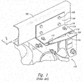
- Figure 1 is an isometric view of a portion of a lift axle system 110 having a hanger bracket 104 attached to a vehicle frame member 102 by a bracket 106 configured in accordance with the prior art.
- Figure 1 illustrates the right (or passenger) side of the vehicle, it will be understood that a mirror image arrangement of the hanger bracket 104, the bracket 106, and the frame member 102 exists on the left (or driver) side of the vehicle as well.
- the bracket 106 includes an upstanding flange that is attached to the frame member 102 by a plurality of bolts 108, and a horizontal flange that is attached to the hanger bracket 104 by a pair of bolts 118 that extend through elongated holes 114.
- both ends of the upper surface of the hanger bracket 104 include a plurality of graduated lines or "tick marks" 112 directly adjacent to an outer edge portion 116 of the bracket 106.
- the elongated holes 114 enable the lift axle system 110 to be moved back and forth in the lateral direction S to center the lift axle system 110 relative to the vehicle frame.
- the installers can verify that the lift axle system 110 is properly aligned by visually inspecting the relative positions of the outer edge portions 116 of the left and right brackets 106 relative to the respective tick marks 112 on the hanger brackets 104.
- Auxiliary suspension system mounting brackets configured in accordance with the present technology can include forward brackets for attaching axle hanger brackets to longitudinal frame members of a vehicle, and rear brackets for attaching axle load springs to the frame members.
- the forward frame brackets can include physical features that facilitate lateral alignment of the axle relative to the vehicle frame during installation. These physical features can include, for example, an outer edge portion of each bracket that includes a series of graduated steps.
- each bracket When the axle is first installed, the stepped edge portion of each bracket is positioned adjacent to a locating surface or other prominent feature of the corresponding hanger bracket. Alignment of the axle can then be readily achieved by visually confirming that the relative position of each of the hanger brackets with respect to the graduated steps on the corresponding frame bracket is the same on both sides of the axle. If not, the axle can be moved from one side to the other as needed to center the axle while the attachment fasteners are slightly loose, and then the attachment fasteners can be fully torqued to their final setting.
- rear frame brackets configured in accordance with the present technology are two-piece brackets having a base portion that is attached to an upper portion of a load spring, and an upper or upstanding portion that is attached to the adjacent frame member. If desired or necessary, the base portion can be disconnected from the upstanding portion while the base portion remains attached to the load spring and the upstanding portion remains attached to the frame member. This enables the load spring to be removed from the axle and replaced or serviced without first having to remove the frame bracket from the frame member.
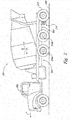
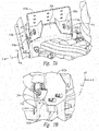
- FIG. 2 is a left side (i.e., driver's side) view of a heavy-duty vehicle 200 having an auxiliary suspension system 210 attached to a chassis 201 with brackets configured in accordance with embodiments of the present technology.
- the auxiliary suspension system 210 is a lift axle system, and may be referred to hereinafter as the lift axle system 210.
- the vehicle 200 includes a cab 206 mounted to the chassis 201.
- the chassis 201 has two laterally spaced-apart, longitudinally extending frame members 202, although only one frame member 202 can be seen in the side view of Figure 2 .
- the lift axle system 210 is attached to the frame members 102 behind tandem axles 204a and 204b in a "tag" configuration.
- One or both of the axles 204 can be drive axles.
- the lift axle system 210 can be positioned between the cab 206 and the axles 204 in a "pusher" configuration.
- Auxiliary axle systems (including both lift and non-lift axles) configured in accordance with the present technology can be used with single drive axles, double drive axles, triple drive axles, etc.
- the lift axle system 210 includes one or more wheels 212 rotatably mounted on opposite sides thereof in a conventional manner. In operation, the lift axle system 210 can raise the wheels 212 off of the ground 208 when the additional support of the lift axle is not needed, and lower the wheels 212 into contact with the ground 208 as shown in Figure 2 when the extra support of the lift axle system 210 is needed or desired.
- the vehicle 200 is pointed in a forward direction F and is aligned with a longitudinal axis L. Additionally, it will be understood that a vertical axis V extends upwardly at a right angle to the longitudinal axis L, and that a lateral axis S (not shown in Figure 2 ) extends horizontally transverse to the longitudinal axis L.
- the vehicle 200 is depicted as a concrete mixer for purposes of illustration, the lift axle systems described herein can be used with virtually any type of heavy duty vehicle including, for example, other types of trucks, trailers, etc., in both "tag” and “pusher” configurations, and with both steerable and non-steerable axles. Accordingly, the various embodiments of the present technology described herein are not limited to use with any particular type of vehicle or in any particular type of axle arrangement unless specifically noted otherwise herein.
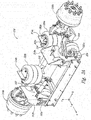
- Figure 3A is an isometric view of a lift axle system 210 having a set of frame brackets 312 and 314 configured in accordance with embodiments of the present technology
- Figure 3B is a partially exploded isometric view of the frame brackets 312 and 314 on the left side of the lift axle system 210.
- the lift axle system 210 includes an axle 316 having wheel hubs 318 (identified individually as a first wheel hub 318a and a second wheel hub 318b) rotatably mounted to opposite end portions thereof in a conventional manner.
- wheel hubs 318 can be mounted to the hubs 318 in a conventional manner.
- the lift axle system 210 further includes a first hanger bracket 322a positioned toward the left side of the vehicle, and a second hanger bracket 322b positioned toward the right side of the vehicle.
- Each of the hanger brackets 322 is attached to a longitudinally-extending frame member (not shown) by a corresponding forward frame bracket 312 (identified individually as a first forward frame bracket 312a and a second forward frame bracket 312b).
- the axle 316 is pivotally coupled to each of the hanger brackets 322 by a corresponding upper control arm 324 and a lower control arm 326.
- First and second load springs 320a and 320b respectively, have lower portions that are attached to opposite sides of the axle 316, and upper portions that are attached to the corresponding frame member by a rear bracket 314 (identified individually as a first rear bracket 314a and a second rear bracket 314b).
- the loads springs 320 are conventional air springs well known in the art which can be inflated in a known manner to lower the lift axle 316, and deflated in a known manner for raising the lift axle 316 by means of, e.g., corresponding lift springs.
- the lift axle system 210 can be at least generally similar in structure and function to lift axle systems described in co-pending U.S. Patent Application No.
- the forward frame bracket 312a includes a base portion 331 and an upstanding portion 333 (which can also be referred to as an "upper portion 333" and the like).
- the base portion 331 includes two horizontally disposed base plates 330 (identified individually as a first base plate 330a and a second base plate 330b) and two vertically disposed flanges 332 (identified individually as a first flange 332a and a second flange 332b) extending downwardly on opposite end portions thereof.
- the upstanding portion 333 includes a vertically disposed back plate 328 that extends upwardly from the horizontally disposed base plates 330 and is supported on opposite ends thereof by corresponding gussets 335.
- each of the base plates 330 includes an outer edge portion 352 that has a series of graduated steps 350. More specifically, the steps 350 (which can also be referred to as tiered or offset edge portions) can be spaced apart from each other by relatively small increments (e.g., equal increments) in the direction of the lateral axis S. For example, in some embodiments the increments can be from about .02 inch to about .5 inch, or about .05 inch to about .25 inch, or about .1 inch. Additionally, in the illustrated embodiment the steps 350 on each of the base plates 330a and 330b are mirror images of each other so that the corresponding steps are aligned with each other in the longitudinal direction L.
- the forward frame bracket 312a can be fixedly attached to the hanger bracket 322a by a pair of threaded studs 336 (identified individually as a first threaded stud 336a and a second threaded stud 336b) that project upwardly from an upper surface 338 of the hanger bracket 322a.
- the studs 336 extend through holes in the base plates 330 that are oversized in at least one direction.
- the studs 336 extend through elongated holes 334 (identified individually as a first elongated hole 334a and a second elongated hole 334b) in the base plates 330 and threadably receive corresponding nuts 344.
- the forward frame bracket 312a is also attached to the hanger bracket 322a by a pair of fasteners, e.g., bolts 342 that extend through elongated holes 340 (identified individually as a first elongated hole 340a and a second elongated hole 340b) in the vertical flange 332 on each end of the frame bracket 312 and threadably engage nut plates 346 on the inside of the hanger bracket 322a.
- elongated holes 340 identified individually as a first elongated hole 340a and a second elongated hole 340b
- each of the elongated holes 340 and 334 are elongated in the direction of the lateral axis S.
- the holes 340 and 334 can be elongated from about .1 inch to about 1 inch or more, or from about .2 inch to about .75 inch. This enables the lift axle system 210 to be moved to the left or right if needed to align or otherwise adjust the position of the lift axle 316 relative to the vehicle frame before the nuts 344 and the bolts 342 have been fully tightened.
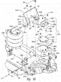
- the rear frame bracket 314a is a two-piece bracket having a base portion 361 and an upstanding portion 363 (which can also be referred to as an "upper portion 363" and the like).
- the base portion 361 includes a horizontally disposed base plate 360 having a first air valve notch 368 toward an inboard side and a second air valve notch 370 toward the opposite outboard side.
- the base plate 360 includes two countersunk holes 366 (identified individually as a first countersunk hole 366a and a second countersunk hole 366b) configured to receive countersunk fasteners 364 (e.g., screws, such as flush head screws) that extend through the holes 366 and engage threaded bores 378 (identified individually as a first threaded bore 378a and a second threaded bore 378b) in a top plate 380 of the load spring 320a to secure the base plate 360 to the top plate 380.
- the base plate 360 further includes square holes 374 (identified individually as a first square hole 374a and a second square hole 374b) which are countersunk on the backside of the base plate 360.
- the square holes 374 are configured to receive countersunk fasteners 382 (e.g., screws, such as flush head screws; identified individually as a first countersunk fastener 382a and a second countersunk fastener 382b) which are trapped between the base plate 360 and the top plate 380 and extend upwardly through the square holes 374.
- the countersunk fasteners 382 can have square shoulders under the heads (similar to a typical carriage bolt) that fit snugly into the square holes 374 to resist turning when nuts 384 are installed and torqued.
- the fasteners 382 can be replaced by threaded studs that are welded directly to the plate 360 or to the plate 380, or by other types of similarly oriented fasteners that do not protrude below the bottom surface of the base plate 360.
- the upstanding portion 363 of the rear frame bracket 314a includes a vertically disposed back plate 362 that extends upwardly from two horizontally disposed base plates 386 (identified individually as a first base plate 386a and a second base plate 386b).
- the base plates 386 are separated by a gap 388 and are reinforced by gussets 390 that extend upwardly between the base plates 386 and the back plate 362.
- Each of the base plates 386 includes a through hole 376 (identified individually as a first through hole 376a and a second through hole 376b) configured to receive one of the fasteners 382.
- the forward frame brackets 312a and 312b are identical, or at least substantially identical, to each other, and the rear frame brackets 314a and 314b are identical, or at least substantially identical, to each other.
- the forward frame brackets 312 and the rear frame brackets 314 can be manufactured using suitable materials and methods well known to those of ordinary skill in the art.
- the frame brackets 312 and 314 can be manufactured from steel plate that is cut and formed to shape and then welded together along abutting edge portions.
- it is contemplated that the frame brackets can be manufactured from other materials using other suitable methods known in the art, such as by machining the brackets from, for example, steel or aluminum castings, forgings, etc.
- Figure 4A is a top view
- Figure 4B is a corresponding front view of the lift axle system 210 mounted to the vehicle frame members 202a and 202b with the forward brackets 312 and the rear brackets 314 in accordance with an embodiment of the present technology.
- the forward frame brackets 312 are attached to the corresponding hanger brackets 322 in such a way that the lift axle 210 will be able to move back and forth parallel to the lateral axis S to adjust the position of the lift axle system 210 relative to the frame members 202.
- the frame brackets 312 can be fixedly attached to the frame members 202 by positioning the horizontal flanges 337 of the respective frame brackets 312 against the lower flanges of the corresponding frame members 202 and installing a plurality of fasteners 404 (e.g., bolts, Huck fasteners, etc.; Figures 4A and 4B ). More specifically, the vertically disposed back plates 328 of the forward frame brackets 312 can include a plurality of pre-existing holes configured to receive the fasteners 404, and these holes can be used to locate new holes in the frame members 202 for the fasteners 404.
- a plurality of fasteners 404 e.g., bolts, Huck fasteners, etc.; Figures 4A and 4B .
- the vertically disposed back plates 328 of the forward frame brackets 312 can include a plurality of pre-existing holes configured to receive the fasteners 404, and these holes can be used to locate new holes in the frame members 202 for the fast
- both parts can have pre-drilled holes positioned to receive the fasteners 404, or both parts can initially be blank and the fastener holes can be match drilled in situ.
- the brackets 312 can be welded to the frame members 202. Either way, once the forward frame brackets 312 have been bolted or otherwise fastened to the corresponding frame members 202, the lateral position of the lift axle system 210 can be adjusted by virtue of the elongated holes 340 and 334 as necessary to center or otherwise align the lift axle system 210 with respect to the frame members 202. The elongated holes 340 and 334 also enable the frame brackets 312 to accommodate different vehicle frame widths.
- the person installing the lift axle system 210 can verify that the lift axle system 210 is properly aligned by visually inspecting the relative positions of the graduated steps 350 with respect to the vertical surface 348 of the corresponding hanger bracket 322. More specifically, referring to Figure 4A , if the graduated steps 350 include a series of three steps 350a-350c, then the position of the steps 350 relative to the vertical surface 348 should be the same (e.g., equal, or at least approximately equal) on both sides of the vehicle.
- the third step 350c of the first frame bracket 312a is flush with the vertical surface 348 on the left side of the vehicle, then the third step 350c on the second frame bracket 312a should also be flush (or at least approximately flush) with the corresponding vertical surface 348 to ensure that the lift axle system 210 is properly aligned (e.g., centered) with respect to the frame members 202. If not, the lift axle system 210 should be moved in the lateral direction as required to center the hanger brackets 322 with respect to the corresponding frame brackets 312 before fully tightening the nuts 344 and the bolts 342.
- the visual alignment aid provided by the stepped-edge feature can eliminate the need for potentially difficult measurements.
- providing the stepped-edge feature in the frame brackets 312 can eliminate the need to provide special alignment features on the hanger brackets 322. Accordingly, it is contemplated that, in some embodiments, the frame brackets 312 can be used to facilitate alignment of a wide variety of auxiliary suspension systems having a variety of different hanger bracket configurations.
- the frame brackets 312 and/or the hanger brackets 322 can include other features to facilitate visual alignment of the lift axle system 210.
- Figure 7A is an outboard isometric view
- Figure 7B is a front isometric view, of other embodiments of the frame bracket 312.
- one or both of the base plates 330a and 330b can include one or more holes 710a and 710b that are positioned over markings 711 (e.g., numbers, letters, etc.), grooves, or other features formed on or in the upper surface 338 of the hanger bracket 322.
- a front and/or rear vertical surface 714 of the hanger brackets 322 can include a series of graduated marks 712 or other features that facilitate side-to-side alignment of the lift axle system 210 by visual comparison to corresponding features (e.g., the edges of the flanges 332) of the frame brackets 312.
- the base plate 360 is positioned so that an air valve 372a is located in the notch 370 or, in the case of the second load spring 320b which has an air valve 372b positioned on the inboard side of the second frame member 202b, the air valve 372b is positioned in the notch 368. Accordingly, the rear frame bracket 314a is able to accommodate a load spring having an air valve on either the inboard or outboard side of the corresponding frame member.
- the countersunk fasteners 364 are inserted through the holes 366 and engaged with the threaded holes 378 in the top plate 380 to fixedly attach the base portion 361 to the top plate 380.
- the upstanding portion 363 of the rear frame bracket 314a can then be attached to the base portion 361 by positioning the base plates 386 on top of the base plate 360 so that the fasteners 382 extend upwardly through the holes 376.
- the nuts 384 are then threadably installed onto the fasteners 382 and can be tightened to full torque.
- the rear frame bracket 314a can then be fixedly attached to the frame member 202a by positioning the base portion 361 against the lower flange of the frame member 202a and installing one or more fasteners, e.g., bolts 406 through the back plate 362 and the frame member 202a as shown in Figures 4A and 4B . More specifically, although not shown in Figures 3A or 3B , the rear frame bracket 314a can include a plurality of pre-drilled holes that can be used to locate corresponding holes in the frame member 202a for receiving the bolts 406. In other embodiments, both the rear frame bracket 314a and the frame member 202a can have pre-drilled holes, or both of these structural elements may be undrilled until installation and then matched drilled in situ.
- the back plate 362 is fixedly bolted otherwise fixedly attached to the frame member 202a to securely attach the upper portion of the load spring 320a to the frame member 202a. Because the fasteners 364 of this embodiment are countersunk, the heads of the fasteners 364 do not interfere with the lower flange of the frame member 202a when the base portion 361 is positioned against the lower flange of the frame member 202a.
- one advantage of the rear frame brackets 314 is that the load springs 320 can be removed and replaced without having to detach the upstanding portions 363 of the frame brackets 314 from the frame members 202.
- the nuts 384 can be removed from the fasteners 382 so that the base portion 361 of the frame bracket 314a can be separated from the upstanding portion 363 while the upstanding portion 363 remains fixedly attached to the frame member 202a. This enables the upper portion of the load spring 320a to be moved downwardly and away from with the frame member 202a for removal from the lift axle 316.
- the nuts 384 should be easily accessible by a person working in the proximity of the lift axle system 210.
- the lower portion of the load spring 320a can be detached from the axle 316 in a known manner and removed, and a new load spring 320a can then be installed by reversing the foregoing process.
- some conventional designs may enable a load spring to be removed without detaching the frame bracket from frame member, these designs may have limitations.
- Figures 5A and 5B are right side (i.e., passenger side) inboard and outboard isometric views, respectively, of a forward frame bracket 512 and a rear frame bracket 514 configured in accordance with other embodiments of the present technology.
- the forward frame bracket 512 can be at least generally similar in structure and function to the forward frame bracket 312 described in detail above.
- the forward frame bracket 512 includes a horizontally disposed flange 530 that is configured to be spaced above the upper surface 338 of the hanger bracket 322.
- the rear frame bracket 514 is at least generally similar in structure and function to the rear frame bracket 314 described in detail above.
- the rear frame bracket 514 is a "one-piece" rear frame bracket in which an upstanding portion 563 is permanently attached (e.g., by welding) to a base portion 561. Additionally, in the illustrated embodiment the rear frame bracket 514 includes a vertically disposed riser 522 having an upper edge portion 532 that is configured to be spaced above the upper surface of the load spring top plate 380.
- the frame brackets 312 and 314 described in detail above are configured for use when the upper surfaces 338 of the hanger brackets 322 and the top plates 380 of the load springs 320 are to be positioned in contact with, or at least relatively close to, the lower horizontal flange of the corresponding frame member 202.
- the frame brackets 512 and 514 illustrated in Figures 5A and 5B can be used by positioning the flange 530 and the upper edge portion 532 against the lower flange of, e.g., the frame member 202b ( Figure 4B ) before bolting the forward frame bracket 512 and the rear frame bracket 514 to the frame member 202b. Because the riser 522 provides space between the lower flange of the frame member 202b and the base portion 561, a person can easily access bolts 584a and 584b to disconnect the upper portion of the load spring 320b from the rear frame bracket 514 without having to disconnect the rear frame bracket 514 from the frame member 202b.
- the rear frame bracket 514 does not have to be a two-piece frame bracket like the frame bracket 314 described in detail above.
- Figures 5A and 5B illustrate the forward frame bracket 512 and the rear frame bracket 514 as used on the right side (passenger side) of the vehicle, the same brackets can be used on the left side of the vehicle by simply reversing their direction.
- Figure 6 illustrates an inboard isometric view of forward frame brackets 612 and 613 superimposed on the forward frame brackets 312 and 512 described in detail above to illustrate how the same basic forward frame bracket can be used to accommodate a variety of different vertical positions of a lift axle system relative to the vehicle frame.
- Figure 6 also illustrates rear frame brackets 614 and 615 superimposed on the rear frame brackets 314 and 514 described above to further illustrate how this type of rear frame bracket can be used to accommodate a variety of lift axle mounting elevations.
- the words “comprise,” “comprising,” and the like are to be construed in an inclusive sense, as opposed to an exclusive or exhaustive sense; that is to say, in the sense of "including, but not limited to.”
- the terms “connected,” “coupled,” or any variant thereof means any connection or coupling, either direct or indirect, between two or more elements; the coupling or connection between the elements can be physical, for fluid (e.g., air) transfer, logical, or a combination thereof.
- the words “herein,” “above,” “below,” and words of similar import when used in this application, refer to this application as a whole and not to any particular portions of this application.
Abstract
Description
- The present application claims the benefit of and priority to
U.S. Provisional Patent Application No. 62/562,210, filed September 22, 2017 - The present disclosure relates generally to brackets for attaching auxiliary suspension systems to the frames of trucks, trailers, and other heavy-lift vehicles.
- Many heavy-duty trucks are designed to carry a wide range of loads that vary depending on the type or amount of cargo they may be carrying. To carry the full range of loads, some trucks include one or more non-drive rear axles in conjunction with one or more drive axles. The non-drive rear axles may be needed for a variety of reasons, such as to comply with suspension and tire load ratings, bridge laws, etc. When the truck is unloaded, the non-drive axle is just "along for the ride," since it is not needed to carry any load in that condition. For this reason, many trucks use non-drive axles that can be lifted off of the ground and into a stored position (the "lifted position" or "raised position") when not needed. This type of axle is often referred to as a "lift axle," a "liftable axle," an "auxiliary axle," and/or an "auxiliary suspension system." By raising the lift axle when the vehicle is lightly loaded, wear on the lift axle tires can be reduced and fuel economy can be increased due to the absence of rolling resistance from the lift axle tires.
- Lift axles can be installed ahead of or behind a drive axle on a straight truck or tractor. If a lift axle is positioned ahead of the drive axle, the lift axle is referred to as a "pusher." If the lift axle is positioned behind the drive axle, it is referred to as a "tag." Lift axles can also be installed ahead of or behind an axle or tandem axles on an articulating trailer. There are both steerable and non-steerable lift axles. As the name implies, the wheels on a non-steerable lift axle cannot turn left or right, and as a result non-steerable lift axles need to be raised prior to turning a tight corner or the tires will scuff and impose high lateral stresses on the wheels and other chassis components. In contrast, steerable lift axles include wheels that can caster so they turn and can remain in contact with the ground during tight turning. Various lift axle systems and associated components are described in
U.S. Patent No. 5,403,031 to Gottschalk et al. ,U.S. Patent No. 6,073,947 to Gottschalk et al. ,U.S. Patent No. 6,311,993 to Hulstein et al. ,U.S. Patent No. 6,880,839 to Keeler et al. ,U.S. Patent No. 9,352,628 to Barton et al. U.S. Patent No. 9,688,318 to Wetter et al. - Lift axle systems are typically attached to the chassis of a truck or other vehicle by a set of brackets. For example, some lift axle systems include two forward hanger brackets that pivotally support the lift axle, and two rearward load springs (e.g., air springs) that are mounted to the lift axle. Such lift axle systems can be attached to the vehicle chassis by two forward brackets and two rear brackets. The two forward brackets attach the two hanger brackets to the two longitudinal frame members, and the two rear brackets attach the two load springs to the two frame members. Often, however, it may be necessary or desirable to adjust the left-to-right position of the lift axle relative to the vehicle frame during installation (or subsequent service) to ensure proper alignment of the axle. Additionally, it may also be necessary or desirable to remove and replace one of load springs without having to detach and then reinstall the corresponding rear frame bracket.
-
Figure 1 is an isometric view of a portion of alift axle system 110 having ahanger bracket 104 attached to avehicle frame member 102 by abracket 106 configured in accordance with the prior art. AlthoughFigure 1 illustrates the right (or passenger) side of the vehicle, it will be understood that a mirror image arrangement of thehanger bracket 104, thebracket 106, and theframe member 102 exists on the left (or driver) side of the vehicle as well. Thebracket 106 includes an upstanding flange that is attached to theframe member 102 by a plurality ofbolts 108, and a horizontal flange that is attached to thehanger bracket 104 by a pair ofbolts 118 that extend throughelongated holes 114. It will be noted that both ends of the upper surface of thehanger bracket 104 include a plurality of graduated lines or "tick marks" 112 directly adjacent to anouter edge portion 116 of thebracket 106. When installing thelift axle system 110 on the vehicle with thebolts 118 not fully tightened, theelongated holes 114 enable thelift axle system 110 to be moved back and forth in the lateral direction S to center thelift axle system 110 relative to the vehicle frame. When in position, the installers can verify that thelift axle system 110 is properly aligned by visually inspecting the relative positions of theouter edge portions 116 of the left andright brackets 106 relative to therespective tick marks 112 on thehanger brackets 104. -
-
Figure 1 is an isometric view of lift axle hanger bracket configured in accordance with the prior art. -
Figure 2 is a side view of a vehicle having a lift axle system mounted to the vehicle chassis with frame brackets configured in accordance with embodiments of the present technology. -
Figure 3A is an isometric view of a lift axle system having frame brackets configured in accordance with embodiments of the present technology, andFigure 3B is a partially exploded isometric view of the frame brackets. -
Figures 4A and4B are top and front views, respectively, of a lift axle system attached to a vehicle frame with the frame brackets ofFigures 3A and3B . -
Figures 5A and 5B are inboard and outboard isometric views, respectively, of forward and aft lift axle frame brackets configured in accordance with another embodiment of the present technology. -
Figure 6 is an inboard isometric view illustrating a range of different sized forward and aft lift axle frame brackets configured in accordance with other embodiments of the present technology. -
Figures 7A and 7B are isometric views of portions of auxiliary suspension mounting systems configured in accordance with further embodiments of the present technology. - The following disclosure describes various embodiments of brackets and other structures for attaching lift axle systems and other auxiliary suspension systems to the chassis of heavy-duty trucks, trailers, and/or other vehicles, and associated methods of manufacture and use. Auxiliary suspension system mounting brackets configured in accordance with the present technology can include forward brackets for attaching axle hanger brackets to longitudinal frame members of a vehicle, and rear brackets for attaching axle load springs to the frame members. In some embodiments, the forward frame brackets can include physical features that facilitate lateral alignment of the axle relative to the vehicle frame during installation. These physical features can include, for example, an outer edge portion of each bracket that includes a series of graduated steps. When the axle is first installed, the stepped edge portion of each bracket is positioned adjacent to a locating surface or other prominent feature of the corresponding hanger bracket. Alignment of the axle can then be readily achieved by visually confirming that the relative position of each of the hanger brackets with respect to the graduated steps on the corresponding frame bracket is the same on both sides of the axle. If not, the axle can be moved from one side to the other as needed to center the axle while the attachment fasteners are slightly loose, and then the attachment fasteners can be fully torqued to their final setting.
- In other embodiments, rear frame brackets configured in accordance with the present technology are two-piece brackets having a base portion that is attached to an upper portion of a load spring, and an upper or upstanding portion that is attached to the adjacent frame member. If desired or necessary, the base portion can be disconnected from the upstanding portion while the base portion remains attached to the load spring and the upstanding portion remains attached to the frame member. This enables the load spring to be removed from the axle and replaced or serviced without first having to remove the frame bracket from the frame member.
- Certain details are set forth in the following description and in
Figures 2-7B to provide a thorough understanding of various embodiments of the present technology. In other instances, well-known structures, systems, materials and/or methods often associated with lift axles systems, metal bracketry, heavy duty trucks and other vehicles, etc. are not shown or described in detail in the following disclosure to avoid unnecessarily obscuring the description of the various embodiments of the technology. Those of ordinary skill in the art will recognize, however, that the present technology can be practiced without one or more of the details set forth herein, and/or with other structures, methods, components, and so forth. The terminology used below is to be interpreted in its broadest reasonable manner, even though it is being used in conjunction with a detailed description of certain examples of embodiments of the technology. Indeed, certain terms may even be emphasized below; however, any terminology intended to be interpreted in any restricted manner will be overtly and specifically defined as such in this Detailed Description section. - The accompanying Figures depict embodiments of the present technology and are not intended to be limiting of its scope. The sizes of various depicted elements are not necessarily drawn to scale, and these elements may be arbitrarily enlarged to improve legibility. In some instances, component details may be abstracted in the Figures to exclude details such as position of components and certain precise connections between such components when such details are unnecessary for a complete understanding of how to make and use the invention. Additionally, many of the details, dimensions, angles and other features shown in the Figures are merely illustrative of particular embodiments of the disclosure. Accordingly, other embodiments can have other details, dimensions, angles and features without departing from the spirit or scope of the present invention. Those of ordinary skill in the art will appreciate that further embodiments of the invention can be practiced without several of the details described below. In the Figures, identical reference numbers identify identical, or at least generally similar, elements. To facilitate the discussion of any particular element, the most significant digit or digits of any reference number refers to the Figure in which that element is first introduced. For example,
element 210 is first introduced and discussed with reference toFigure 2 . -
Figure 2 is a left side (i.e., driver's side) view of a heavy-duty vehicle 200 having anauxiliary suspension system 210 attached to achassis 201 with brackets configured in accordance with embodiments of the present technology. In the illustrated embodiment, theauxiliary suspension system 210 is a lift axle system, and may be referred to hereinafter as thelift axle system 210. However, it will be understood that embodiments of the apparatuses, systems and methods described herein can be used with other auxiliary suspension systems including, for example, non-lifting axles. Thevehicle 200 includes acab 206 mounted to thechassis 201. Thechassis 201 has two laterally spaced-apart, longitudinally extendingframe members 202, although only oneframe member 202 can be seen in the side view ofFigure 2 . In the illustrated embodiment, thelift axle system 210 is attached to theframe members 102 behindtandem axles 204a and 204b in a "tag" configuration. One or both of the axles 204 can be drive axles. In other embodiments, thelift axle system 210 can be positioned between thecab 206 and the axles 204 in a "pusher" configuration. Auxiliary axle systems (including both lift and non-lift axles) configured in accordance with the present technology can be used with single drive axles, double drive axles, triple drive axles, etc. Thelift axle system 210 includes one ormore wheels 212 rotatably mounted on opposite sides thereof in a conventional manner. In operation, thelift axle system 210 can raise thewheels 212 off of theground 208 when the additional support of the lift axle is not needed, and lower thewheels 212 into contact with theground 208 as shown inFigure 2 when the extra support of thelift axle system 210 is needed or desired. - For directional reference in the discussion that follows, it will be understood that the
vehicle 200 is pointed in a forward direction F and is aligned with a longitudinal axis L. Additionally, it will be understood that a vertical axis V extends upwardly at a right angle to the longitudinal axis L, and that a lateral axis S (not shown inFigure 2 ) extends horizontally transverse to the longitudinal axis L. Although thevehicle 200 is depicted as a concrete mixer for purposes of illustration, the lift axle systems described herein can be used with virtually any type of heavy duty vehicle including, for example, other types of trucks, trailers, etc., in both "tag" and "pusher" configurations, and with both steerable and non-steerable axles. Accordingly, the various embodiments of the present technology described herein are not limited to use with any particular type of vehicle or in any particular type of axle arrangement unless specifically noted otherwise herein. -
Figure 3A is an isometric view of alift axle system 210 having a set offrame brackets Figure 3B is a partially exploded isometric view of theframe brackets lift axle system 210. Referring first toFigure 3A , in the illustrated embodiment thelift axle system 210 includes anaxle 316 having wheel hubs 318 (identified individually as afirst wheel hub 318a and asecond wheel hub 318b) rotatably mounted to opposite end portions thereof in a conventional manner. Although not shown inFigures 3A and3B , wheels can be mounted to the hubs 318 in a conventional manner. Thelift axle system 210 further includes afirst hanger bracket 322a positioned toward the left side of the vehicle, and asecond hanger bracket 322b positioned toward the right side of the vehicle. Each of thehanger brackets 322 is attached to a longitudinally-extending frame member (not shown) by a corresponding forward frame bracket 312 (identified individually as a firstforward frame bracket 312a and a secondforward frame bracket 312b). In the illustrated embodiment, theaxle 316 is pivotally coupled to each of thehanger brackets 322 by a correspondingupper control arm 324 and alower control arm 326. First and second load springs 320a and 320b, respectively, have lower portions that are attached to opposite sides of theaxle 316, and upper portions that are attached to the corresponding frame member by a rear bracket 314 (identified individually as a firstrear bracket 314a and a secondrear bracket 314b). In the illustrated embodiments, the loads springs 320 are conventional air springs well known in the art which can be inflated in a known manner to lower thelift axle 316, and deflated in a known manner for raising thelift axle 316 by means of, e.g., corresponding lift springs. In some embodiments, thelift axle system 210 can be at least generally similar in structure and function to lift axle systems described in co-pendingU.S. Patent Application No. 15/701,369, filed September 11, 2017 - Referring next to
Figure 3B , theforward frame bracket 312a includes abase portion 331 and an upstanding portion 333 (which can also be referred to as an "upper portion 333" and the like). In the illustrated embodiment, thebase portion 331 includes two horizontally disposed base plates 330 (identified individually as afirst base plate 330a and asecond base plate 330b) and two vertically disposed flanges 332 (identified individually as afirst flange 332a and asecond flange 332b) extending downwardly on opposite end portions thereof. Theupstanding portion 333 includes a vertically disposed backplate 328 that extends upwardly from the horizontally disposed base plates 330 and is supported on opposite ends thereof by correspondinggussets 335. In the illustrated embodiment, a horizontally disposedflange 337 extends inwardly from theback plate 328 generally opposite the base plates 330. In the illustrated embodiment, each of the base plates 330 includes anouter edge portion 352 that has a series ofgraduated steps 350. More specifically, the steps 350 (which can also be referred to as tiered or offset edge portions) can be spaced apart from each other by relatively small increments (e.g., equal increments) in the direction of the lateral axis S. For example, in some embodiments the increments can be from about .02 inch to about .5 inch, or about .05 inch to about .25 inch, or about .1 inch. Additionally, in the illustrated embodiment thesteps 350 on each of thebase plates - The
forward frame bracket 312a can be fixedly attached to thehanger bracket 322a by a pair of threaded studs 336 (identified individually as a first threadedstud 336a and a second threadedstud 336b) that project upwardly from anupper surface 338 of thehanger bracket 322a. In some embodiments, the studs 336 extend through holes in the base plates 330 that are oversized in at least one direction. For example, in the illustrated embodiment the studs 336 extend through elongated holes 334 (identified individually as a firstelongated hole 334a and a second elongated hole 334b) in the base plates 330 and threadably receive corresponding nuts 344. In the illustrated embodiment, theforward frame bracket 312a is also attached to thehanger bracket 322a by a pair of fasteners, e.g.,bolts 342 that extend through elongated holes 340 (identified individually as a firstelongated hole 340a and a second elongated hole 340b) in the vertical flange 332 on each end of theframe bracket 312 and threadably engagenut plates 346 on the inside of thehanger bracket 322a. As illustrated inFigure 3B , each of the elongated holes 340 and 334 are elongated in the direction of the lateral axis S. For example, the holes 340 and 334 can be elongated from about .1 inch to about 1 inch or more, or from about .2 inch to about .75 inch. This enables thelift axle system 210 to be moved to the left or right if needed to align or otherwise adjust the position of thelift axle 316 relative to the vehicle frame before thenuts 344 and thebolts 342 have been fully tightened. - In the illustrated embodiment, the
rear frame bracket 314a is a two-piece bracket having abase portion 361 and an upstanding portion 363 (which can also be referred to as an "upper portion 363" and the like). Thebase portion 361 includes a horizontally disposedbase plate 360 having a firstair valve notch 368 toward an inboard side and a secondair valve notch 370 toward the opposite outboard side. Additionally, thebase plate 360 includes two countersunk holes 366 (identified individually as a first countersunk hole 366a and a secondcountersunk hole 366b) configured to receive countersunk fasteners 364 (e.g., screws, such as flush head screws) that extend through the holes 366 and engage threaded bores 378 (identified individually as a first threaded bore 378a and a second threadedbore 378b) in atop plate 380 of theload spring 320a to secure thebase plate 360 to thetop plate 380. Thebase plate 360 further includes square holes 374 (identified individually as a firstsquare hole 374a and a secondsquare hole 374b) which are countersunk on the backside of thebase plate 360. The square holes 374 are configured to receive countersunk fasteners 382 (e.g., screws, such as flush head screws; identified individually as a firstcountersunk fastener 382a and a secondcountersunk fastener 382b) which are trapped between thebase plate 360 and thetop plate 380 and extend upwardly through the square holes 374. The countersunk fasteners 382 can have square shoulders under the heads (similar to a typical carriage bolt) that fit snugly into the square holes 374 to resist turning whennuts 384 are installed and torqued. In other embodiments, the fasteners 382 can be replaced by threaded studs that are welded directly to theplate 360 or to theplate 380, or by other types of similarly oriented fasteners that do not protrude below the bottom surface of thebase plate 360. - In the illustrated embodiment, the
upstanding portion 363 of therear frame bracket 314a includes a vertically disposed backplate 362 that extends upwardly from two horizontally disposed base plates 386 (identified individually as afirst base plate 386a and asecond base plate 386b). The base plates 386 are separated by agap 388 and are reinforced bygussets 390 that extend upwardly between the base plates 386 and theback plate 362. Each of the base plates 386 includes a through hole 376 (identified individually as a first throughhole 376a and a second throughhole 376b) configured to receive one of the fasteners 382. In the illustrated embodiments, theforward frame brackets rear frame brackets forward frame brackets 312 and therear frame brackets 314 can be manufactured using suitable materials and methods well known to those of ordinary skill in the art. For example, in some embodiments theframe brackets -
Figure 4A is a top view, andFigure 4B is a corresponding front view of thelift axle system 210 mounted to thevehicle frame members forward brackets 312 and therear brackets 314 in accordance with an embodiment of the present technology. Referring toFigures 3A-4B together, to install thelift axle system 210 on the vehicle chassis, theforward frame brackets 312 are attached to thecorresponding hanger brackets 322 in such a way that thelift axle 210 will be able to move back and forth parallel to the lateral axis S to adjust the position of thelift axle system 210 relative to theframe members 202. This is accomplished by positioning theforward frame brackets 312 on thecorresponding hanger brackets 322 such that the threaded studs 336 extend upwardly through the elongated holes 334, and then installing thenuts 344 on the studs 336 and installing thebolts 342 through the elongated holes 340 to engage thecorresponding nut plates 346. Then thenuts 344 and thebolts 342 can be tightened enough to remove any appreciable gaps between theforward frame brackets 312 and thehanger brackets 322, but still permit side to side movement of thehanger bracket 322 relative to theframe bracket 312 by means of the elongated holes 340 and 334. - Once the
forward frame brackets 312 have been installed on thecorresponding hanger brackets 322 in this manner, theframe brackets 312 can be fixedly attached to theframe members 202 by positioning thehorizontal flanges 337 of therespective frame brackets 312 against the lower flanges of thecorresponding frame members 202 and installing a plurality of fasteners 404 (e.g., bolts, Huck fasteners, etc.;Figures 4A and4B ). More specifically, the vertically disposed backplates 328 of theforward frame brackets 312 can include a plurality of pre-existing holes configured to receive thefasteners 404, and these holes can be used to locate new holes in theframe members 202 for thefasteners 404. Alternatively, both parts can have pre-drilled holes positioned to receive thefasteners 404, or both parts can initially be blank and the fastener holes can be match drilled in situ. In other embodiments, thebrackets 312 can be welded to theframe members 202. Either way, once theforward frame brackets 312 have been bolted or otherwise fastened to thecorresponding frame members 202, the lateral position of thelift axle system 210 can be adjusted by virtue of the elongated holes 340 and 334 as necessary to center or otherwise align thelift axle system 210 with respect to theframe members 202. The elongated holes 340 and 334 also enable theframe brackets 312 to accommodate different vehicle frame widths. Moreover, the person installing thelift axle system 210 can verify that thelift axle system 210 is properly aligned by visually inspecting the relative positions of the graduatedsteps 350 with respect to thevertical surface 348 of thecorresponding hanger bracket 322. More specifically, referring toFigure 4A , if the graduatedsteps 350 include a series of threesteps 350a-350c, then the position of thesteps 350 relative to thevertical surface 348 should be the same (e.g., equal, or at least approximately equal) on both sides of the vehicle. For example, if thethird step 350c of thefirst frame bracket 312a is flush with thevertical surface 348 on the left side of the vehicle, then thethird step 350c on thesecond frame bracket 312a should also be flush (or at least approximately flush) with the correspondingvertical surface 348 to ensure that thelift axle system 210 is properly aligned (e.g., centered) with respect to theframe members 202. If not, thelift axle system 210 should be moved in the lateral direction as required to center thehanger brackets 322 with respect to thecorresponding frame brackets 312 before fully tightening thenuts 344 and thebolts 342. The visual alignment aid provided by the stepped-edge feature can eliminate the need for potentially difficult measurements. Additionally, in some embodiments providing the stepped-edge feature in theframe brackets 312 can eliminate the need to provide special alignment features on thehanger brackets 322. Accordingly, it is contemplated that, in some embodiments, theframe brackets 312 can be used to facilitate alignment of a wide variety of auxiliary suspension systems having a variety of different hanger bracket configurations. - In other embodiments, the
frame brackets 312 and/or thehanger brackets 322 can include other features to facilitate visual alignment of thelift axle system 210. For example,Figure 7A is an outboard isometric view, andFigure 7B is a front isometric view, of other embodiments of theframe bracket 312. As shown inFigure 7A , in some embodiments one or both of thebase plates more holes upper surface 338 of thehanger bracket 322. During installation, the person or persons installing thelift axle system 210 can confirm proper alignment by visually confirming that thefeatures 711 on theupper surfaces 338 of therespective hanger brackets 322 which show through the holes 710 in the corresponding frame bracket base plates 330 are in the same relative position on both sides. In further embodiments, as shown inFigure 7B , a front and/or rearvertical surface 714 of thehanger brackets 322 can include a series of graduatedmarks 712 or other features that facilitate side-to-side alignment of thelift axle system 210 by visual comparison to corresponding features (e.g., the edges of the flanges 332) of theframe brackets 312. - Returning to
Figures 3A-4B , for ease of understanding, attachment of the load springs 320 to theframe members 202 is described below with respect to thefirst load spring 320a, with the understanding the same process applies to attachment of thesecond load spring 320b. To attach thefirst load spring 320a to thefirst frame member 202a, thebase portion 361 of therear frame bracket 314a is separated from theupper portion 363, and thebase plate 360 is positioned on thetop plate 380 of theload spring 320a with the fasteners 382 extending upwardly through the square holes 374 (Figure 3B ). Thebase plate 360 is positioned so that anair valve 372a is located in thenotch 370 or, in the case of thesecond load spring 320b which has anair valve 372b positioned on the inboard side of thesecond frame member 202b, theair valve 372b is positioned in thenotch 368. Accordingly, therear frame bracket 314a is able to accommodate a load spring having an air valve on either the inboard or outboard side of the corresponding frame member. Next, the countersunkfasteners 364 are inserted through the holes 366 and engaged with the threaded holes 378 in thetop plate 380 to fixedly attach thebase portion 361 to thetop plate 380. Theupstanding portion 363 of therear frame bracket 314a can then be attached to thebase portion 361 by positioning the base plates 386 on top of thebase plate 360 so that the fasteners 382 extend upwardly through the holes 376. Thenuts 384 are then threadably installed onto the fasteners 382 and can be tightened to full torque. - The
rear frame bracket 314a can then be fixedly attached to theframe member 202a by positioning thebase portion 361 against the lower flange of theframe member 202a and installing one or more fasteners, e.g.,bolts 406 through theback plate 362 and theframe member 202a as shown inFigures 4A and4B . More specifically, although not shown inFigures 3A or3B , therear frame bracket 314a can include a plurality of pre-drilled holes that can be used to locate corresponding holes in theframe member 202a for receiving thebolts 406. In other embodiments, both therear frame bracket 314a and theframe member 202a can have pre-drilled holes, or both of these structural elements may be undrilled until installation and then matched drilled in situ. With either approach, theback plate 362 is fixedly bolted otherwise fixedly attached to theframe member 202a to securely attach the upper portion of theload spring 320a to theframe member 202a. Because thefasteners 364 of this embodiment are countersunk, the heads of thefasteners 364 do not interfere with the lower flange of theframe member 202a when thebase portion 361 is positioned against the lower flange of theframe member 202a. - As noted above, one advantage of the
rear frame brackets 314 is that the load springs 320 can be removed and replaced without having to detach theupstanding portions 363 of theframe brackets 314 from theframe members 202. For example, if theload spring 320a needs to be removed for maintenance or replacement after thelift axle system 210 has been in service, thenuts 384 can be removed from the fasteners 382 so that thebase portion 361 of theframe bracket 314a can be separated from theupstanding portion 363 while theupstanding portion 363 remains fixedly attached to theframe member 202a. This enables the upper portion of theload spring 320a to be moved downwardly and away from with theframe member 202a for removal from thelift axle 316. As can be seen with reference toFigures 3B and4A , thenuts 384 should be easily accessible by a person working in the proximity of thelift axle system 210. Once the upper portion of theload spring 320a has been detached from theupstanding portion 363 of theframe bracket 314a, the lower portion of theload spring 320a can be detached from theaxle 316 in a known manner and removed, and anew load spring 320a can then be installed by reversing the foregoing process. Although some conventional designs may enable a load spring to be removed without detaching the frame bracket from frame member, these designs may have limitations. For example, conventional designs that utilize two studs to attach the load spring to the frame bracket (one outboard of the frame member and one inboard) may require notching of the lower flange of the frame member to clear the inboard stud. Embodiments of the present technology, however, can be used with wide flange frame members without this limitation. -
Figures 5A and 5B are right side (i.e., passenger side) inboard and outboard isometric views, respectively, of aforward frame bracket 512 and arear frame bracket 514 configured in accordance with other embodiments of the present technology. Referring toFigures 5A and 5B together, theforward frame bracket 512 can be at least generally similar in structure and function to theforward frame bracket 312 described in detail above. In the illustrated embodiment, however, theforward frame bracket 512 includes a horizontally disposedflange 530 that is configured to be spaced above theupper surface 338 of thehanger bracket 322. Therear frame bracket 514 is at least generally similar in structure and function to therear frame bracket 314 described in detail above. However, in the illustrated embodiment therear frame bracket 514 is a "one-piece" rear frame bracket in which anupstanding portion 563 is permanently attached (e.g., by welding) to abase portion 561. Additionally, in the illustrated embodiment therear frame bracket 514 includes a vertically disposedriser 522 having anupper edge portion 532 that is configured to be spaced above the upper surface of the loadspring top plate 380. - As can be seen with reference to, for example,
Figure 4B , theframe brackets upper surfaces 338 of thehanger brackets 322 and thetop plates 380 of the load springs 320 are to be positioned in contact with, or at least relatively close to, the lower horizontal flange of thecorresponding frame member 202. In other applications, for example, in other applications in which the vehicle has a higher frame height and/or may be using smaller wheels on the axle, it may be desirable to position thelift axle system 210 below the lower flange of theframe members 202 by a selected distance, such as a distance ranging from about 1 inch to about 12 inches, or various distances therebetween. In such embodiments, theframe brackets Figures 5A and 5B can be used by positioning theflange 530 and theupper edge portion 532 against the lower flange of, e.g., theframe member 202b (Figure 4B ) before bolting theforward frame bracket 512 and therear frame bracket 514 to theframe member 202b. Because theriser 522 provides space between the lower flange of theframe member 202b and thebase portion 561, a person can easily accessbolts 584a and 584b to disconnect the upper portion of theload spring 320b from therear frame bracket 514 without having to disconnect therear frame bracket 514 from theframe member 202b. Accordingly, for this reason in some embodiments therear frame bracket 514 does not have to be a two-piece frame bracket like theframe bracket 314 described in detail above. However, in some embodiments, it may be advantageous for theframe bracket 514 to be in two-piece form like theframe bracket 314 to, for example, provide better tool access to fasteners. AlthoughFigures 5A and 5B illustrate theforward frame bracket 512 and therear frame bracket 514 as used on the right side (passenger side) of the vehicle, the same brackets can be used on the left side of the vehicle by simply reversing their direction. -
Figure 6 illustrates an inboard isometric view offorward frame brackets forward frame brackets Figure 6 also illustratesrear frame brackets rear frame brackets - ADDITIONAL EXAMPLES:
- 1. An auxiliary suspension system for use with a vehicle having a frame, the auxiliary suspension system comprising:
- a load spring; and
- a bracket configured to operably couple the load spring to the frame, wherein the bracket includes -
- a first portion configured to be fixedly attached to an upper portion of the load spring; and
- a second portion configured to be fixedly attached to the vehicle frame and removably attached to the first portion, wherein the first portion is configured to be detached from the second portion and subsequently reattached to the second portion while the first portion remains fixedly attached to the load spring and the second portion remains fixedly attached to the vehicle frame.
- 2. The auxiliary suspension system of example 1:
- wherein the first portion of the bracket includes a horizontally disposed base plate configured to receive one or more first fasteners for fixedly attaching the base plate to the upper portion of the load spring, and
- wherein the second portion of the bracket includes a vertically disposed back plate configured to receive one or more second fasteners for fixedly attaching the back plate to the vehicle frame.
- 3. The auxiliary suspension system of example 2:
- wherein the base plate of the first portion is a first base plate, and
- wherein the second portion of the bracket further includes a second horizontally disposed base plate configured to receive one or more third fasteners for removably attaching the second base plate to the first base plate.
- 4. The auxiliary suspension of example 1, further comprising:
- one or more first fasteners configured to be engaged with both the first portion of the bracket and the upper portion of the load spring to fixedly attach the first portion of the bracket to the upper portion of the load spring; and
- one or more second fasteners configured to be engaged with both the first portion of the bracket and the second portion of the bracket to removably attach the first portion of the bracket to the second portion of the bracket.
- 5. The auxiliary suspension of example 4 wherein the one or more second fasteners are further configured to be disengaged from at least one of the first portion of the bracket or the second portion of the bracket to release the second portion of the bracket from the first portion of the bracket while the one or more first fasteners remain engaged with both the first portion of the bracket and the upper portion of the load spring to fixedly attach the first portion of the bracket to the upper portion of the load spring.
- 6. The auxiliary suspension of example 5 wherein the upper portion of the load spring includes a top plate having one or more threaded holes, and wherein the one or more first fasteners are configured to threadably engage the threaded holes.
- 7. The auxiliary suspension of example 6 wherein the one or more first fasteners are countersunk fasteners.
- 8. The auxiliary suspension system of example 1:
- wherein the load spring is an air spring having an air fitting extending from the upper portion,
- wherein the first portion of the bracket includes a horizontally disposed base plate having an opening, and
- wherein the air fitting is positioned within the opening when the base plate is attached to the upper portion of the load spring.
- 9. A frame bracket for attaching an auxiliary suspension system to a vehicle frame, the auxiliary suspension system including an axle having at least one wheel rotatably mounted at each end portion thereof, the frame bracket comprising:
- at least one aperture configured to receive a fastener for attaching the frame bracket to the auxiliary suspension system, wherein the at least one aperture is oversized along an axis; and
- at least one physical feature shaped and positioned to facilitate visual alignment of the axle relative to the vehicle frame during installation of the auxiliary suspension system.
- 10. The frame bracket of example 9 wherein the at least one aperture is elongated along a lateral axis, and wherein the at least one physical feature is shaped and positioned to facilitate lateral alignment of the axle relative to the vehicle frame during installation of the auxiliary suspension system.
- 11. The frame bracket of example 9 wherein the at least one physical feature includes an edge portion having a series of steps formed thereon, wherein the steps are offset relative to each other in the direction of the axis, and wherein the steps are configured to be positioned proximate a physical feature of the auxiliary suspension system to facilitate visual alignment of the axle relative to the vehicle frame during installation of the auxiliary suspension system.
- 12. The frame bracket of example 9 wherein the auxiliary suspension system further includes a hanger bracket, wherein the axle is movably coupled to the hanger bracket, and wherein the frame bracket further comprises:
- a horizontally disposed base plate, wherein the at least one aperture is formed in the base plate and is configured to receive a fastener for fixedly attaching the frame bracket to the hanger bracket, and wherein the at least one physical feature includes an edge portion of the base plate that has a series of steps formed thereon, wherein the steps are offset relative to each other in the direction of the axis, and wherein the steps are configured to be positioned proximate a physical feature of the hanger bracket to facilitate visual alignment of the axle relative to the vehicle frame during installation of the auxiliary suspension system.
- 13. The frame bracket of example 12 wherein the hanger bracket includes a vertical surface, and wherein the steps on the edge portion of the base plate are configured to be positioned relative to the vertical surface of hanger bracket to facilitate visual alignment of the axle relative to the vehicle frame during installation of the auxiliary suspension system.
- 14. The frame bracket of example 12 wherein the hanger bracket includes a vertical surface, and wherein the steps on the edge portion of the base plate are configured to be aligned with the vertical surface of hanger bracket to facilitate visual alignment of the axle relative to the vehicle frame during installation of the auxiliary suspension system.
- 15. The frame bracket of example 9 wherein the auxiliary suspension system further includes a hanger bracket, wherein the axle is movably coupled to the hanger bracket, and wherein the frame bracket further comprises:
- a horizontally disposed base plate, wherein the at least one aperture is formed in the base plate and is configured to receive a fastener for fixedly attaching the frame bracket to the hanger bracket; and
- a vertically disposed flange extending downwardly from the base plate, wherein the vertically disposed flange includes the at least one physical feature.
- 16. The frame bracket of example 9 wherein the auxiliary suspension system further includes a hanger bracket, wherein the axle is movably coupled to the hanger bracket, and wherein the frame bracket further comprises:
- a horizontally disposed base plate, wherein the at least one aperture is a first elongated aperture formed in the base plate; and
- a vertically disposed flange extending downwardly from the base plate, wherein the vertically disposed flange includes a second elongated aperture, and wherein the first and second elongated apertures are configured to receive corresponding fasteners for fixedly attaching the frame bracket to the hanger bracket.
- 17. The frame bracket of example 9 wherein the vehicle frame includes a lower flange, wherein the auxiliary suspension system further includes a hanger bracket, wherein the axle is movably coupled to the hanger bracket, and wherein the frame bracket further comprises:
- a horizontally disposed base plate, wherein the at least one aperture is formed in the base plate and is configured to receive a fastener for fixedly attaching the frame bracket to the hanger bracket; and
- a horizontally disposed member spaced above the base plate, wherein the horizontally disposed member is configured to be positioned against the lower flange of the vehicle frame.
- 18. The frame bracket of example 17, further comprising a vertically disposed back plate extending upwardly from the base plate, wherein the base plate extends outwardly from a first side of the back plate, and wherein the horizontally disposed member extends outwardly from a second side of the back plate, opposite to the first side.
- 19. A method of attaching an auxiliary suspension system to a vehicle frame, wherein the vehicle frame includes a first frame member spaced apart from a second frame member, wherein the auxiliary suspension system includes a first hanger bracket, a second hanger bracket spaced apart from the first hanger bracket, and an axle movably coupled to the first and second hanger brackets, and wherein the method comprises:
- loosely attaching a first frame bracket to the first hanger bracket, wherein the first frame bracket includes at least a first physical feature shaped and positioned to facilitate visual alignment of the first hanger bracket relative to the first frame bracket;
- loosely attaching a second frame bracket to the second hanger bracket, wherein the second frame bracket includes at least a second physical feature shaped and positioned to facilitate visual alignment of the second hanger bracket relative to the second frame bracket;
- fixedly attaching the first frame bracket to the first frame member;
- fixedly attaching the second frame bracket to the second frame member;
- visually inspecting a first position of the first physical feature relative to the first hanger bracket;
- visually inspecting a second position of the second physical feature relative to the second hanger bracket;
- comparing the first position to the second position;
- aligning the auxiliary suspension system relative to the frame based on the comparison of the first position to the second position; and
- after aligning the auxiliary suspension system, fixedly attaching the first and second frame brackets to the first and second frame members, respectively.
- 20. The method of example 19:
- wherein the first physical feature is a first stepped edge portion and the second physical feature is a second stepped edge portion, and
- wherein aligning the auxiliary suspension system includes positioning the auxiliary suspension system so that the position of the first stepped edge portion relative to the first hanger bracket is at least approximately equal to the position of the second stepped edge portion relative to the second hanger bracket.
- References throughout the foregoing description to features, advantages, or similar language do not imply that all of the features and advantages that may be realized with the present technology should be or are in any single embodiment of the invention. Rather, language referring to the features and advantages is understood to mean that a specific feature, advantage, or characteristic described in connection with an embodiment is included in at least one embodiment of the present technology. Thus, discussion of the features and advantages, and similar language, throughout this specification may, but do not necessarily, refer to the same embodiment. Furthermore, the described features, advantages, and characteristics of the present technology may be combined in any suitable manner in one or more embodiments. One skilled in the relevant art will recognize that the present technology can be practiced without one or more of the specific features or advantages of a particular embodiment. In other instances, additional features and advantages may be recognized in certain embodiments that may not be present in all embodiments of the present technology.
- Any patents and applications and other references noted above, including any that may be listed in accompanying filing papers, are incorporated herein by reference. Aspects of the invention can be modified, if necessary, to employ the systems, functions, and concepts of the various references described above to provide yet further implementations of the invention.
- Unless the context clearly requires otherwise, throughout the description and the claims, the words "comprise," "comprising," and the like are to be construed in an inclusive sense, as opposed to an exclusive or exhaustive sense; that is to say, in the sense of "including, but not limited to." As used herein, the terms "connected," "coupled," or any variant thereof means any connection or coupling, either direct or indirect, between two or more elements; the coupling or connection between the elements can be physical, for fluid (e.g., air) transfer, logical, or a combination thereof. Additionally, the words "herein," "above," "below," and words of similar import, when used in this application, refer to this application as a whole and not to any particular portions of this application. Where the context permits, words in the above Detailed Description using the singular or plural number may also include the plural or singular number respectively. The word "or," in reference to a list of two or more items, covers all of the following interpretations of the word: any of the items in the list, all of the items in the list, and any combination of the items in the list.
- The above Detailed Description of examples and embodiments of the invention is not intended to be exhaustive or to limit the invention to the precise form disclosed above. While specific examples for the invention are described above for illustrative purposes, various equivalent modifications are possible within the scope of the invention, as those skilled in the relevant art will recognize. The teachings of the invention provided herein can be applied to other systems, not necessarily the system described above. The elements and acts of the various examples described above can be combined to provide further implementations of the invention. Some alternative implementations of the invention may include not only additional elements to those implementations noted above, but also may include fewer elements. Further any specific numbers noted herein are only examples: alternative implementations may employ differing values or ranges.
- While the above description describes various embodiments of the invention and the best mode contemplated, regardless how detailed the above text, the invention can be practiced in many ways. Details of the system may vary considerably in its specific implementation, while still being encompassed by the present disclosure. As noted above, particular terminology used when describing certain features or aspects of the invention should not be taken to imply that the terminology is being redefined herein to be restricted to any specific characteristics, features, or aspects of the invention with which that terminology is associated. In general, the terms used in the following claims should not be construed to limit the invention to the specific examples disclosed in the specification, unless the above Detailed Description section explicitly defines such terms. Accordingly, the actual scope of the invention encompasses not only the disclosed examples, but also all equivalent ways of practicing or implementing the invention under the claims. From the foregoing, it will be appreciated that specific embodiments of the invention have been described herein for purposes of illustration, but that various modifications may be made without deviating from the spirit and scope of the various embodiments of the invention. Accordingly, the invention is not limited, except as by the appended claims.
- Although certain aspects of the invention are presented below in certain claim forms, the applicant contemplates the various aspects of the invention in any number of claim forms. Accordingly, the applicant reserves the right to pursue additional claims after filing this application to pursue such additional claim forms, in either this application or in a continuing application.
Claims (20)
- An auxiliary suspension system for use with a vehicle having a frame, the auxiliary suspension system comprising:a load spring; anda bracket configured to operably couple the load spring to the frame, wherein the bracket includes -a first portion configured to be fixedly attached to an upper portion of the load spring; anda second portion configured to be fixedly attached to the vehicle frame and removably attached to the first portion, wherein the first portion is configured to be detached from the second portion and subsequently reattached to the second portion while the first portion remains fixedly attached to the load spring and the second portion remains fixedly attached to the vehicle frame.
- The auxiliary suspension system of claim 1:wherein the first portion of the bracket includes a horizontally disposed base plate configured to receive one or more first fasteners for fixedly attaching the base plate to the upper portion of the load spring, andwherein the second portion of the bracket includes a vertically disposed back plate configured to receive one or more second fasteners for fixedly attaching the back plate to the vehicle frame.
- The auxiliary suspension system of claim 2:wherein the base plate of the first portion is a first base plate, andwherein the second portion of the bracket further includes a second horizontally disposed base plate configured to receive one or more third fasteners for removably attaching the second base plate to the first base plate.
- The auxiliary suspension of claim 1, further comprising:one or more first fasteners configured to be engaged with both the first portion of the bracket and the upper portion of the load spring to fixedly attach the first portion of the bracket to the upper portion of the load spring; andone or more second fasteners configured to be engaged with both the first portion of the bracket and the second portion of the bracket to removably attach the first portion of the bracket to the second portion of the bracket.
- The auxiliary suspension of claim 4 wherein the one or more second fasteners are further configured to be disengaged from at least one of the first portion of the bracket or the second portion of the bracket to release the second portion of the bracket from the first portion of the bracket while the one or more first fasteners remain engaged with both the first portion of the bracket and the upper portion of the load spring to fixedly attach the first portion of the bracket to the upper portion of the load spring.
- The auxiliary suspension of claim 5 wherein the upper portion of the load spring includes a top plate having one or more threaded holes, and wherein the one or more first fasteners are configured to threadably engage the threaded holes.
- The auxiliary suspension of claim 6 wherein the one or more first fasteners are countersunk fasteners.
- The auxiliary suspension system of claim 1:wherein the load spring is an air spring having an air fitting extending from the upper portion,wherein the first portion of the bracket includes a horizontally disposed base plate having an opening, andwherein the air fitting is positioned within the opening when the base plate is attached to the upper portion of the load spring.
- A frame bracket for attaching an auxiliary suspension system to a vehicle frame, the auxiliary suspension system including an axle having at least one wheel rotatably mounted at each end portion thereof, the frame bracket comprising:at least one aperture configured to receive a fastener for attaching the frame bracket to the auxiliary suspension system, wherein the at least one aperture is oversized along an axis; andat least one physical feature shaped and positioned to facilitate visual alignment of the axle relative to the vehicle frame during installation of the auxiliary suspension system.
- The frame bracket of claim 9 wherein the at least one aperture is elongated along a lateral axis, and wherein the at least one physical feature is shaped and positioned to facilitate lateral alignment of the axle relative to the vehicle frame during installation of the auxiliary suspension system.
- The frame bracket of claim 9 wherein the at least one physical feature includes an edge portion having a series of steps formed thereon, wherein the steps are offset relative to each other in the direction of the axis, and wherein the steps are configured to be positioned proximate a physical feature of the auxiliary suspension system to facilitate visual alignment of the axle relative to the vehicle frame during installation of the auxiliary suspension system.
- The frame bracket of claim 9 wherein the auxiliary suspension system further includes a hanger bracket, wherein the axle is movably coupled to the hanger bracket, and wherein the frame bracket further comprises:a horizontally disposed base plate, wherein the at least one aperture is formed in the base plate and is configured to receive a fastener for fixedly attaching the frame bracket to the hanger bracket, and wherein the at least one physical feature includes an edge portion of the base plate that has a series of steps formed thereon, wherein the steps are offset relative to each other in the direction of the axis, and wherein the steps are configured to be positioned proximate a physical feature of the hanger bracket to facilitate visual alignment of the axle relative to the vehicle frame during installation of the auxiliary suspension system.
- The frame bracket of claim 12 wherein the hanger bracket includes a vertical surface, and wherein the steps on the edge portion of the base plate are configured to be positioned relative to the vertical surface of hanger bracket to facilitate visual alignment of the axle relative to the vehicle frame during installation of the auxiliary suspension system.
- The frame bracket of claim 12 wherein the hanger bracket includes a vertical surface, and wherein the steps on the edge portion of the base plate are configured to be aligned with the vertical surface of hanger bracket to facilitate visual alignment of the axle relative to the vehicle frame during installation of the auxiliary suspension system.
- The frame bracket of claim 9 wherein the auxiliary suspension system further includes a hanger bracket, wherein the axle is movably coupled to the hanger bracket, and wherein the frame bracket further comprises:a horizontally disposed base plate, wherein the at least one aperture is formed in the base plate and is configured to receive a fastener for fixedly attaching the frame bracket to the hanger bracket; anda vertically disposed flange extending downwardly from the base plate, wherein the vertically disposed flange includes the at least one physical feature.
- The frame bracket of claim 9 wherein the auxiliary suspension system further includes a hanger bracket, wherein the axle is movably coupled to the hanger bracket, and wherein the frame bracket further comprises:a horizontally disposed base plate, wherein the at least one aperture is a first elongated aperture formed in the base plate; anda vertically disposed flange extending downwardly from the base plate, wherein the vertically disposed flange includes a second elongated aperture, and wherein the first and second elongated apertures are configured to receive corresponding fasteners for fixedly attaching the frame bracket to the hanger bracket.
- The frame bracket of claim 9 wherein the vehicle frame includes a lower flange, wherein the auxiliary suspension system further includes a hanger bracket, wherein the axle is movably coupled to the hanger bracket, and wherein the frame bracket further comprises:a horizontally disposed base plate, wherein the at least one aperture is formed in the base plate and is configured to receive a fastener for fixedly attaching the frame bracket to the hanger bracket; anda horizontally disposed member spaced above the base plate, wherein the horizontally disposed member is configured to be positioned against the lower flange of the vehicle frame.
- The frame bracket of claim 17, further comprising a vertically disposed back plate extending upwardly from the base plate, wherein the base plate extends outwardly from a first side of the back plate, and wherein the horizontally disposed member extends outwardly from a second side of the back plate, opposite to the first side.
- A method of attaching an auxiliary suspension system to a vehicle frame, wherein the vehicle frame includes a first frame member spaced apart from a second frame member, wherein the auxiliary suspension system includes a first hanger bracket, a second hanger bracket spaced apart from the first hanger bracket, and an axle movably coupled to the first and second hanger brackets, and wherein the method comprises:loosely attaching a first frame bracket to the first hanger bracket, wherein the first frame bracket includes at least a first physical feature shaped and positioned to facilitate visual alignment of the first hanger bracket relative to the first frame bracket;loosely attaching a second frame bracket to the second hanger bracket, wherein the second frame bracket includes at least a second physical feature shaped and positioned to facilitate visual alignment of the second hanger bracket relative to the second frame bracket;fixedly attaching the first frame bracket to the first frame member;fixedly attaching the second frame bracket to the second frame member;visually inspecting a first position of the first physical feature relative to the first hanger bracket;visually inspecting a second position of the second physical feature relative to the second hanger bracket;comparing the first position to the second position;aligning the auxiliary suspension system relative to the frame based on the comparison of the first position to the second position; andafter aligning the auxiliary suspension system, fixedly attaching the first and second frame brackets to the first and second frame members, respectively.
- The method of claim 19:wherein the first physical feature is a first stepped edge portion and the second physical feature is a second stepped edge portion, andwherein aligning the auxiliary suspension system includes positioning the auxiliary suspension system so that the position of the first stepped edge portion relative to the first hanger bracket is at least approximately equal to the position of the second stepped edge portion relative to the second hanger bracket.
Applications Claiming Priority (1)
| Application Number | Priority Date | Filing Date | Title |
|---|---|---|---|
| US201762562210P | 2017-09-22 | 2017-09-22 |
Publications (2)
| Publication Number | Publication Date |
|---|---|
| EP3482978A2 true EP3482978A2 (en) | 2019-05-15 |
| EP3482978A3 EP3482978A3 (en) | 2019-09-04 |
Family
ID=63678462
Family Applications (1)
| Application Number | Title | Priority Date | Filing Date |
|---|---|---|---|
| EP18195895.0A Withdrawn EP3482978A3 (en) | 2017-09-22 | 2018-09-21 | Mounting brackets for auxiliary suspension systems |
Country Status (2)
| Country | Link |
|---|---|
| US (3) | US10967927B2 (en) |
| EP (1) | EP3482978A3 (en) |
Cited By (1)
| Publication number | Priority date | Publication date | Assignee | Title |
|---|---|---|---|---|
| USD969677S1 (en) * | 2019-11-05 | 2022-11-15 | Firestone Industrial Products Company, Llc | Mounting bracket |
Families Citing this family (7)
| Publication number | Priority date | Publication date | Assignee | Title |
|---|---|---|---|---|
| US10569813B2 (en) | 2016-12-23 | 2020-02-25 | Link Mfg., Ltd. | Cab suspension systems and associated methods of manufacture and use |
| US10654330B2 (en) * | 2016-12-30 | 2020-05-19 | Club Car, Llc | Suspension bracket for a utility vehicle |
| US10967927B2 (en) | 2017-09-22 | 2021-04-06 | Link Mfg., Ltd. | Mounting brackets for auxiliary suspension systems |
| US10953939B2 (en) * | 2018-03-08 | 2021-03-23 | Oshkosh Corporation | Load span tag axle system |
| US11104389B2 (en) * | 2018-03-31 | 2021-08-31 | Jeffrey William Ash | Clamping system |
| US11472247B2 (en) | 2019-10-01 | 2022-10-18 | Firestone Industrial Products Company, Llc | Mounting bracket assemblies as well as suspension assemblies, kits and methods including same |
| WO2023283464A1 (en) * | 2021-07-08 | 2023-01-12 | Link Mfg., Ltd. | Driven lift axles and associated systems and methods |
Citations (6)
| Publication number | Priority date | Publication date | Assignee | Title |
|---|---|---|---|---|
| US5403031A (en) | 1993-12-08 | 1995-04-04 | The Boler Company | Parallelogram lift axle suspension system with a control for axle caster adjustment |
| US6073947A (en) | 1998-03-31 | 2000-06-13 | The Boler Company | Substantially weld free frame bracket assembly |
| US6311993B1 (en) | 2000-10-18 | 2001-11-06 | Link Mfg., Ltd. | Lift axle suspension mounting system |
| US6880839B2 (en) | 2003-03-11 | 2005-04-19 | Boler Company | In-line lift axle suspension system |
| US9352628B2 (en) | 2014-05-22 | 2016-05-31 | Ridewell Corporation | Lift suspension system with offset control arms |
| US9688318B1 (en) | 2015-06-26 | 2017-06-27 | Link Mfg., Ltd. | Axle suspension mounting system |
Family Cites Families (211)
| Publication number | Priority date | Publication date | Assignee | Title |
|---|---|---|---|---|
| DE747806C (en) | 1938-05-15 | 1944-10-16 | Rear axle drive for motor vehicles | |
| GB908693A (en) | 1958-02-15 | 1962-10-24 | Dunlop Rubber Co | Improvements in vehicle suspension systems and devices for use therein |
| FR1237549A (en) | 1958-10-18 | 1960-07-29 | Daimler Benz Ag | Elastic suspension of a rigid axle for vehicles, in particular for motor cars |
| US3246716A (en) | 1963-10-29 | 1966-04-19 | Ford Motor Co | Vehicle suspension system |
| DE1430878A1 (en) | 1964-02-29 | 1970-01-22 | Daimler Benz Ag | Axle suspension for motor vehicles, especially with a rigid axle |
| US3575441A (en) | 1968-12-23 | 1971-04-20 | Ford Motor Co | Vehicle suspension |
| US3653683A (en) | 1970-05-18 | 1972-04-04 | Hendrickson Mfg Co | Vehicle suspension system |
| US3630541A (en) | 1970-06-11 | 1971-12-28 | Int Harvester Co | Vehicle axle suspension |
| US3733087A (en) | 1970-12-21 | 1973-05-15 | Ford Motor Co | Independent suspension system for a motor vehicle |
| US3730548A (en) | 1971-06-24 | 1973-05-01 | Ride Rite Corp | Vehicle air-spring |
| CA1002988A (en) | 1973-09-13 | 1977-01-04 | London Concrete Machinery Co. (A Division Of Hodgson Machine And Equipme Nt Ltd.) | Mobile load bearing equipment |
| US3850445A (en) | 1974-02-11 | 1974-11-26 | Lear Siegler Inc | Combined air spring and leaf spring suspension |
| US3992036A (en) | 1975-07-07 | 1976-11-16 | Ford Motor Company | Independent front suspension system for a motor vehicle |
| SE429118B (en) | 1975-10-14 | 1983-08-15 | Maschf Augsburg Nuernberg Ag | Axle suspension for vehicles with air or screw suspension, STELA AXLAR |
| DE2649990C2 (en) | 1976-10-30 | 1985-10-17 | Daimler-Benz Ag, 7000 Stuttgart | Independent wheel suspension for motor vehicles |
| US4350358A (en) | 1978-05-08 | 1982-09-21 | Ferris Tom E | Auxiliary load-carrying apparatus |
| JPS5649610U (en) | 1979-09-25 | 1981-05-01 | ||
| JPS56106907U (en) | 1980-01-18 | 1981-08-20 | ||
| US4267896A (en) | 1980-02-04 | 1981-05-19 | Hendriksen Errol C | Method and apparatus for aligning automobile suspension members |
| US4458915A (en) | 1980-11-19 | 1984-07-10 | Ford Motor Company | Motor vehicle wheel suspension |
| US4415179A (en) | 1981-04-15 | 1983-11-15 | Marinelli Joseph A | Axle and air bag suspension |
| US4518171A (en) | 1983-10-14 | 1985-05-21 | Hedenberg William E | Air suspension system |
| US4759567A (en) | 1985-12-17 | 1988-07-26 | Silentride Suspensions Limited | Air suspension system |
| US4934667A (en) | 1986-08-13 | 1990-06-19 | General Motors Corporation | Air spring damper for vehicle suspension |
| US4802690A (en) | 1986-11-12 | 1989-02-07 | Raidel John E | Suspension assembly for steer axle with single air spring mounted directly over the axle |
| US4736964A (en) | 1986-12-29 | 1988-04-12 | Specktor Gerald A | Locking cam for adjustment of automobile wheel alignment |
| US4756550A (en) | 1987-01-27 | 1988-07-12 | Raidel John E | Suspension assembly with compound parallelogram |
| US4856814A (en) | 1987-02-05 | 1989-08-15 | Jones Everett W | Adjustable, proportionally steerable auxiliary wheel asemblies for trucks |
| US4809960A (en) | 1987-03-26 | 1989-03-07 | Nissan Motor Co., Ltd. | Bushing assembly |
| US4869527A (en) | 1987-07-17 | 1989-09-26 | Coddens Douglas W | Vehicle wheel alignment device |
| US4792148A (en) | 1987-08-11 | 1988-12-20 | Hintz John C | Semi-trailer truck |
| US4900057A (en) | 1988-07-18 | 1990-02-13 | Raidel John E | Suspension system with pivotally connected A-frame parallelogram |
| DE3933163A1 (en) | 1988-10-27 | 1990-05-03 | Toyoda Gosei Kk | CYLINDRICAL DAMPING BUSH |
| DE8915893U1 (en) | 1989-04-26 | 1991-11-28 | Bergische Achsenfabrik Fr. Kotz & Soehne, 5276 Wiehl, De | |
| US5018756A (en) | 1989-10-23 | 1991-05-28 | Ridewell Corporation | Control for self steering suspension assembly |
| US5163699A (en) | 1989-12-29 | 1992-11-17 | Shim-A-Line, Inc. | Cam washer for adjusting wheel alignment |
| US5083812A (en) | 1990-05-21 | 1992-01-28 | Neway Corp. | Suspension with stiffener arm |
| US5265907A (en) * | 1991-03-05 | 1993-11-30 | Ray Tostado | Auxiliary suspension assembly for Ford "F" and "E" series trucks |
| EP0503213A1 (en) | 1991-03-08 | 1992-09-16 | The Pullman Company | Improved rubber-metal bushing and method of producing same |
| JP2952794B2 (en) | 1991-12-10 | 1999-09-27 | 本田技研工業株式会社 | Method of manufacturing suspension member for vehicle |
| US5230528A (en) | 1991-12-23 | 1993-07-27 | Van Raden Industries, Inc. | Lift axle wheel assembly |
| GB9213268D0 (en) | 1992-06-23 | 1992-08-05 | Rover Group | A suspension system for a vehicle |
| US5251926A (en) | 1992-07-06 | 1993-10-12 | General Motors Corporation | Ratchet assembly for an adjustable stabilizer bar |
| DE4224288A1 (en) | 1992-07-23 | 1994-01-27 | Porsche Ag | Double wishbone axle |
| US5301977A (en) | 1992-11-02 | 1994-04-12 | Specialty Products Company | Method and apparatus for adjusting toe and/or camber |
| GB9223618D0 (en) | 1992-11-11 | 1992-12-23 | Rover Group | A vehicle supsension torque arm assembly and a vehicle incorporating same |
| US5368326A (en) | 1993-07-01 | 1994-11-29 | Ford Motor Company | Apparatus for insuring neutral stabilizer bar installation |
| JP3374503B2 (en) * | 1994-02-28 | 2003-02-04 | いすゞ自動車株式会社 | Mounting structure of vehicle start-up assist device |
| US5505481A (en) | 1994-03-07 | 1996-04-09 | Suspensions Incorporated | Lift axle suspension system |
| US5505482A (en) | 1994-08-24 | 1996-04-09 | Suspensions Incorporated | Road-railer suspension system having a spring lift and a stabilizer bar |
| US5718445A (en) | 1994-08-24 | 1998-02-17 | Suspensions, Inc. | Vehicle suspension system |
| JP3085117B2 (en) | 1995-01-11 | 2000-09-04 | トヨタ自動車株式会社 | Suspension device |
| US5579860A (en) | 1995-03-28 | 1996-12-03 | Ottawa Truck, Inc. | Three-point cab mounting system for a one man cab using one rear mount |
| US5785345A (en) | 1995-10-16 | 1998-07-28 | The Boler Company | Means for and method of controlling frame rise in vehicle suspensions |
| US5678845A (en) | 1996-01-29 | 1997-10-21 | Reyco Industries, Inc. | Stabilizer for a steer axle air ride suspension of a vehicle |
| US5649719A (en) | 1996-02-23 | 1997-07-22 | The Boler Company. | Linkage suspension system |
| US5924712A (en) | 1996-05-30 | 1999-07-20 | Neway Anchorlok International, Inc. | Dual trailing arm vehicle suspension |
| TW445224B (en) | 1997-03-25 | 2001-07-11 | Toyoda Automatic Loom Works | Axle controller for industrial vehicles |
| US5944339A (en) | 1997-05-06 | 1999-08-31 | Meritor Heavy Vehicle Systems, Llc | Integrated axle suspension anti-roll arrangement for push-pull suspension |
| JP3724120B2 (en) | 1997-05-26 | 2005-12-07 | いすゞ自動車株式会社 | Rear biaxial vehicle suspension system |
| US6073946A (en) | 1997-07-16 | 2000-06-13 | Neway Anchorlok International, Inc. | Trailing arm suspension |
| US5988672A (en) | 1997-08-11 | 1999-11-23 | Meritor Heavy Vehicle Suspension Systems, Inc. | Suspension system with integral box beam |
| SE513393C2 (en) | 1997-10-21 | 2000-09-04 | Volvo Lastvagnar Ab | Wheel axle suspension for a vehicle |
| US6158750A (en) | 1998-05-29 | 2000-12-12 | Fluidrive, Inc. | Lift axle assembly |
| US6135470A (en) * | 1998-06-01 | 2000-10-24 | The Boler Company | Transverse stabilizer for wheel axle suspension system |
| US6131930A (en) * | 1998-06-11 | 2000-10-17 | Watson & Chalin Manufacturing, Inc. | Axle alignment system |
| CA2308025A1 (en) | 1998-08-27 | 2000-03-09 | Holland Neway International, Inc. | Drive axle suspension |
| CA2350624A1 (en) | 1998-11-11 | 2000-05-18 | Kenmar Company Trust | Enhanced computer optimized adaptive suspension system and method |
| US6398236B1 (en) | 1999-07-16 | 2002-06-04 | Holland Neway International, Inc. | Lift axle suspension with axle reservoir |
| US6416069B1 (en) | 1999-08-16 | 2002-07-09 | The Boler Company | Underbeam axle lift assembly |
| US6808192B1 (en) | 1999-11-24 | 2004-10-26 | The Holland Group, Inc. | Trailing arm suspension |
| US6712923B2 (en) | 2000-01-12 | 2004-03-30 | Toyota Jidosha Kabushiki Kaisha | Manufacturing apparatus and manufacturing method of solid polymer film with catalyst deposited thereon |
| US20010052685A1 (en) * | 2000-06-16 | 2001-12-20 | Svartz Bjorn O. | Suspension |
| US6367826B1 (en) | 2000-07-13 | 2002-04-09 | Daimlerchrysler Corporation | Camber/caster adjuster |
| DE10057191B4 (en) | 2000-11-17 | 2005-08-25 | Zf Boge Elastmetall Gmbh | Hydraulically damping rubber mount |
| US6527286B2 (en) | 2000-12-06 | 2003-03-04 | The Boler Company | Vehicle suspension assembly |
| US6851689B2 (en) | 2001-02-26 | 2005-02-08 | The Boler Company | Vehicle suspension |
| US6945548B2 (en) | 2001-02-26 | 2005-09-20 | Hendrickson Usa, L.L.C. | Air spring and air spring mounting assembly |
| US6607205B2 (en) | 2001-02-26 | 2003-08-19 | Meritor Heavy Vehicle Systems L.L.C. | Steerable independent air suspension system |
| US7044458B2 (en) | 2001-04-30 | 2006-05-16 | Maclean-Fogg Company | Stabilizer bar |
| US6832143B2 (en) | 2001-07-30 | 2004-12-14 | Hadley Products | Drive train vibration control system |
| US20030057622A1 (en) | 2001-09-27 | 2003-03-27 | Bovio Vincent G. | Slipper bushing |
| CA2467651C (en) | 2001-12-19 | 2007-11-13 | The Boler Company | Air spring control system for a vehicle' s lift axle |
| US20030151222A1 (en) | 2002-02-12 | 2003-08-14 | Sutton Anthony D. | Lift axle control and module |
| US6834873B1 (en) | 2002-02-21 | 2004-12-28 | Link Mfg., Ltd. | Axle suspension system |
| US6824144B2 (en) | 2002-04-16 | 2004-11-30 | Ross Operating Valve Company | Kneeling valve |
| US6666474B2 (en) | 2002-05-17 | 2003-12-23 | Meritor Heavy Vehicle Technology Llc | Semi-balanced tandem suspension |
| US6758648B1 (en) | 2002-06-17 | 2004-07-06 | Link Mfg., Ltd. | Deathcare apparatus for transporting multiple caskets, cots, stretchers, cremation trays or the like |
| US6886840B2 (en) | 2002-07-12 | 2005-05-03 | Arvinmeritor Technology, Llc | Heavy duty trailing arm suspension system |
| US7967307B2 (en) | 2002-07-12 | 2011-06-28 | Arvinmeritor Technology, Llc | Heavy duty trailing arm suspension system |
| US6871864B2 (en) | 2002-07-12 | 2005-03-29 | Arvinmeritor Technology, Llc | Trailing arm suspension anti-roll bar |
| WO2004007148A1 (en) | 2002-07-16 | 2004-01-22 | The Boler Company | Improved fixture and method for assembling structures |
| US6659479B1 (en) | 2002-07-18 | 2003-12-09 | Ridewell Corporation | Adjustable suspension hanger assembly |
| US6886266B2 (en) | 2002-09-06 | 2005-05-03 | The Boler Company | Vehicle alignment measurement apparatus and method |
| ATE426544T1 (en) | 2002-10-30 | 2009-04-15 | Hendrickson Int Corp | FASTENING THE STEERING DAMPER AND REVERSING LOCK TO THE CARRIER |
| US7125026B2 (en) | 2002-11-01 | 2006-10-24 | Newfrey Llc | Cam-bolt assembly |
| US6851687B2 (en) | 2002-11-26 | 2005-02-08 | Daimlerchrysler Corporation | Off-axis cam adjustment system and method |
| US8544864B2 (en) | 2003-01-15 | 2013-10-01 | Saf-Holland, Inc. | Vehicle suspension assembly |
| US7234713B1 (en) | 2003-02-21 | 2007-06-26 | Link Mfg. Ltd. | Axle suspension system |
| US6957819B2 (en) | 2003-06-20 | 2005-10-25 | Watson & Chalin Manufacturing, Inc. | Lift axle parallelogram suspension system |
| US7464948B2 (en) | 2003-09-17 | 2008-12-16 | Hendrickson Usa, L.L.C. | Distributed compliance axle/suspension system |
| US7503586B2 (en) | 2003-09-22 | 2009-03-17 | Hendrickson Usa, L.L.C. | Vehicle frame having air tank cross member |
| US7455306B2 (en) | 2003-10-17 | 2008-11-25 | Hendrickson Usa, L.L.C. | Integral arm axle/suspension system |
| WO2005052386A2 (en) | 2003-11-19 | 2005-06-09 | Alpha Stamping Company | Fastener assembly |
| AU2004298496B2 (en) | 2003-12-10 | 2008-12-04 | Hendrickson International Corporation | Steerable axle automatic lift sensor system |
| US7083176B2 (en) | 2004-01-06 | 2006-08-01 | General Motors Corporation | Wheel alignment arrangements for vehicles |
| US20050156398A1 (en) | 2004-01-16 | 2005-07-21 | John Edward Ramsey | Device for leveling a trailer floor |
| US7261304B2 (en) | 2004-01-27 | 2007-08-28 | Hadley Products | Vehicle leveling system |
| MXPA06011207A (en) | 2004-04-02 | 2007-08-14 | Hendrickson Int Corp | Hanger-free movable subframe for tractor-trailers. |
| US7331588B2 (en) | 2004-06-17 | 2008-02-19 | Saf-Holland, Inc. | Trailing beam suspension with alignment adjustment assembly |
| US20050280238A1 (en) | 2004-06-18 | 2005-12-22 | The Boler Company | Roll stable vehicle suspension system |
| US20060001311A1 (en) | 2004-07-01 | 2006-01-05 | Platner David K | Front steer axle air suspension system |
| US6932401B1 (en) | 2004-10-11 | 2005-08-23 | Link Mfg., Ltd. | Casket transporting apparatus |
| US7281721B2 (en) | 2004-12-03 | 2007-10-16 | Watson & Chalin Manufacturing, Inc. | Suspension system for dump truck/paver truck hitch |
| SE528079C2 (en) | 2004-12-30 | 2006-08-29 | Volvo Lastvagnar Ab | Air spring for lifting a vehicle axle and vehicles fitted with such an air spring |
| US8403346B2 (en) | 2005-01-20 | 2013-03-26 | Watson & Chalin Manufacturring, Inc. | Adjustable run height lift axle suspension system |
| US7014237B1 (en) | 2005-01-24 | 2006-03-21 | Link Mfg., Ltd. | Casket transporting apparatus |
| CA2596579A1 (en) | 2005-02-01 | 2006-08-10 | Hendrickson International Corporation | Frame or subframe for tractor-trailers |
| US7216925B1 (en) | 2005-02-07 | 2007-05-15 | Link Mfg., Ltd. | Height control linkage for a vehicle cab suspension |
| US20060181043A1 (en) * | 2005-02-16 | 2006-08-17 | Zebolsky Michael L | Rotary cam alignment system |
| US7296809B2 (en) | 2005-02-16 | 2007-11-20 | Hendrickson Usa, L.L.C. | Rotary cam alignment system |
| SE0500485L (en) | 2005-03-02 | 2006-06-27 | Volvo Lastvagnar Ab | Suspension arrangement for vehicles |
| US7607670B2 (en) | 2005-04-20 | 2009-10-27 | Ridewell Corporation | Wedged axle connection |
| US7392996B2 (en) * | 2005-04-20 | 2008-07-01 | Ridewell Corporation | Apparatus for establishing a caster angle of a vehicle suspension system |
| US20060244236A1 (en) | 2005-04-27 | 2006-11-02 | Cortez Jerome L | Vehicle suspensions having leaf springs and alternative clamp groups |
| US7293781B2 (en) | 2005-04-29 | 2007-11-13 | Hendrickson Usa, L.L.C. | Anti-creep trailer locking mechanism |
| NZ561184A (en) | 2005-04-29 | 2010-12-24 | Hendrickson Int Corp | Heavy-duty vehicle axle-suspension system with beam of composite material and constant cross-section |
| US8047558B2 (en) | 2005-04-29 | 2011-11-01 | Hendrickson Usa, L.L.C. | Heavy-duty vehicle axle/suspension system |
| US7331627B2 (en) | 2005-05-19 | 2008-02-19 | Joel Dean Van Den Brink | Lateral control rod for a cab suspension system |
| CA2608899C (en) | 2005-06-30 | 2009-09-22 | Hendrickson International Corporation | Movable subframe for tractor-trailers |
| US7416190B2 (en) | 2005-09-01 | 2008-08-26 | Arlin Gene Sandbulte | Air suspension system for a vehicle |
| AU2006342140B2 (en) | 2005-11-18 | 2010-09-16 | Hendrickson International Corporation | Frame for heavy-duty vehicles |
| US7481441B2 (en) | 2005-12-01 | 2009-01-27 | Ridewell Corporation | Slotted axle assembly |
| US7600785B2 (en) | 2006-03-16 | 2009-10-13 | Hendrickson Usa, L.L.C. | Frame for heavy-duty vehicles |
| DE102006038523A1 (en) | 2006-04-29 | 2007-10-31 | Daimlerchrysler Ag | Spring damping unit for a vehicle comprises a rolling piston which is able slide through a housing part using a sealing element |
| US7735516B2 (en) | 2006-05-16 | 2010-06-15 | Norgren Gt Development Corporation | Lift axle control module |
| US7891679B2 (en) | 2006-08-09 | 2011-02-22 | Volvo Group North America, Llc | Adjustment arrangement in a suspension hanger assembly |
| GB0619981D0 (en) | 2006-10-10 | 2006-11-15 | Meritor Heavy Vehicle Sys Ltd | Suspension sub-assembly |
| WO2008070779A2 (en) | 2006-12-06 | 2008-06-12 | The Braun Corporation | Wireless vehicle access control system |
| US7816878B2 (en) | 2007-02-01 | 2010-10-19 | The Braun Corporation | Vehicle access control system |
| US20080185549A1 (en) | 2007-02-02 | 2008-08-07 | Steinbuchel Herman J | Differential valve |
| US7690660B2 (en) | 2007-03-29 | 2010-04-06 | Hendrickson Usa, L.L.C. | Leading and trailing arm suspensions having a fully integrated arm |
| US10836232B2 (en) | 2007-04-12 | 2020-11-17 | Haldex Brake Products Corporation | Electronic height control system for a vehicle with multiple input signals |
| US20090060640A1 (en) | 2007-09-04 | 2009-03-05 | Richard Gregory Vogler | Lightweight heavy duty bushing with easy assembly |
| US7731208B2 (en) | 2008-02-15 | 2010-06-08 | Brooks Strong | Tag axle operating system |
| US8302988B2 (en) | 2008-03-10 | 2012-11-06 | Hendrickson Usa, L.L.C. | Suspension assembly with tie-plate |
| US7789405B2 (en) | 2008-07-14 | 2010-09-07 | Link Manufacturing, Ltd. | Linkage-type air suspension system |
| US7887065B2 (en) | 2009-02-24 | 2011-02-15 | Hadley Products | Height control valve for vehicle leveling system |
| US20110035104A1 (en) | 2009-04-15 | 2011-02-10 | Judson Smith | Suspension conversion method and apparatus |
| US8371596B2 (en) | 2009-05-13 | 2013-02-12 | Saf-Holland, Inc. | Suspension system for heavy and vocational vehicles |
| US7966685B2 (en) | 2009-07-14 | 2011-06-28 | Link Manufacturing Ltd | Pocket ramp |
| DE102010016768A1 (en) * | 2010-05-04 | 2011-11-10 | Contitech Luftfedersysteme Gmbh | Air spring arrangement for a commercial vehicle |
| US8523208B2 (en) * | 2010-05-04 | 2013-09-03 | Timbren Industries Inc. | Independent suspension mechanism |
| US8459400B2 (en) | 2010-05-25 | 2013-06-11 | Ridewell Corporation | Force steer axle assembly with redundant centering |
| US8979105B2 (en) | 2010-12-17 | 2015-03-17 | Bbs Development, Llc | Adjustable mounting assembly for vehicle leaf spring |
| US8590912B2 (en) | 2010-12-17 | 2013-11-26 | Bbs Development, Llc | Adjustable mounting assembly for vehicle leaf spring |
| DE102011001431B4 (en) * | 2011-03-21 | 2022-09-29 | Bpw Bergische Achsen Kg | Axle lift for a vehicle axle |
| US8955902B2 (en) | 2011-05-11 | 2015-02-17 | Caterpillar Inc. | Universal fastening device |
| WO2012158793A1 (en) | 2011-05-17 | 2012-11-22 | Hendrickson Usa, L.L.C. | Piston for an air spring of a heavy-duty vehicle |
| WO2012170610A1 (en) * | 2011-06-07 | 2012-12-13 | Hendrickson Usa, L.L.C. | Slider box for a heavy- duty vehicle |
| US8523207B2 (en) * | 2011-09-12 | 2013-09-03 | Watson & Chalin Manufacturing, Inc. | Device for attaching a suspension to a vehicle frame and related method |
| US8641062B2 (en) | 2011-10-07 | 2014-02-04 | Hendrickson Usa, L.L.C. | Lift axle suspension systems incorporating compression coil springs |
| US8413997B1 (en) | 2011-11-21 | 2013-04-09 | Air Lift Company | System for controlling a fluid suspension |
| US8622406B2 (en) | 2012-01-13 | 2014-01-07 | Nicholas Eveley | Trailing beam mounting and alignment apparatus |
| US8573611B1 (en) | 2012-10-03 | 2013-11-05 | Kenneth D. Jensen | Emergency safety system for vehicles with supplemental axles |
| US8727363B1 (en) | 2012-11-06 | 2014-05-20 | Transportation Technologies, Inc. | Suspension system having parallel air spring and rubber force reaction |
| BR112015013114B1 (en) | 2012-12-05 | 2021-05-11 | Mack Trucks, Inc | vehicle with multi-wheel drive axle mounting with a raising and lowering rear drive wheel axle, and method of neutralizing the rear drive wheel axle and operating such a vehicle |
| US8967639B2 (en) | 2013-01-28 | 2015-03-03 | Saf-Holland, Inc. | Auxiliary axle and suspension assembly |
| DE102013003300A1 (en) | 2013-02-28 | 2014-08-28 | Bpw Bergische Achsen Kg | Chassis for a commercial vehicle, axle body and method for producing an axle body |
| US9139061B2 (en) | 2013-04-03 | 2015-09-22 | Watson & Chalin Manufacturing, Inc. | Vehicle suspension system with reservoir for air spring damping |
| WO2015005831A1 (en) | 2013-07-11 | 2015-01-15 | Volvo Truck Corporation | Vehicle suspension and leaf spring therefore |
| DE102013214737A1 (en) * | 2013-07-29 | 2015-01-29 | Saf-Holland Gmbh | handlebar unit |
| US9233589B1 (en) | 2013-09-17 | 2016-01-12 | Northstar Manufacturing Co., Inc. | Cam bolt apparatus for suspension systems |
| US9272594B2 (en) | 2013-11-15 | 2016-03-01 | Continental Automotive Systems, Inc. | System and method of using air suspension to improve vehicle unloading |
| USD727219S1 (en) | 2013-11-25 | 2015-04-21 | Hadley Products Corporation | Vehicular component linkage member |
| US9315083B2 (en) * | 2014-07-15 | 2016-04-19 | Hendrickson Usa, L.L.C. | Frame hanger for providing thrust angle alignment in vehicle suspension |
| CA2942527C (en) | 2014-08-12 | 2017-01-17 | Watson & Chalin Manufacturing, Inc. | Tag axle suspension system with tire at lowest point when lifted |
| JP3196517U (en) * | 2014-12-04 | 2015-03-19 | 有限会社カーセールス・ワタナベ | Lower bracket and air spring mounting structure |
| JP2016151347A (en) | 2015-02-19 | 2016-08-22 | Ntn株式会社 | Twin-motor vehicle driving device |
| US9422014B1 (en) | 2015-02-25 | 2016-08-23 | Arvinmeritor Technology, Llc | Axle lift system and method of control |
| MX2017011672A (en) | 2015-03-20 | 2017-11-06 | Hendrickson Usa Llc | Hanger for axle/suspension systems. |
| US9358854B1 (en) | 2015-06-17 | 2016-06-07 | Link, Mfg., Ltd. | Air suspension control system for a vehicle |
| US9315222B1 (en) * | 2015-07-14 | 2016-04-19 | Link Mfg., Ltd. | Adjustment means for a suspension hanger assembly |
| US20170016757A1 (en) | 2015-07-18 | 2017-01-19 | Brooks Strong | Axle Load Monitoring System |
| US9340242B1 (en) | 2015-10-12 | 2016-05-17 | Link Mfg., Ltd. | Adjustable king pin assembly |
| US9829060B2 (en) | 2016-01-08 | 2017-11-28 | Hendrickson Usa, L.L.C. | Armored air spring assembly |
| US9776677B2 (en) | 2016-02-10 | 2017-10-03 | Kelly W YAKIMISHYN | Lift axle suspension |
| CN106183684B (en) * | 2016-07-01 | 2018-08-31 | 湖南晟通天力汽车有限公司 | Automobile-used connecting bracket |
| DE202016004580U1 (en) | 2016-07-25 | 2016-10-27 | Liebherr-Werk Ehingen Gmbh | Axle |
| US9937766B1 (en) | 2016-12-15 | 2018-04-10 | Link Mfg., Ltd. | Height control linkage for a vehicle cab suspension system |
| US10569813B2 (en) | 2016-12-23 | 2020-02-25 | Link Mfg., Ltd. | Cab suspension systems and associated methods of manufacture and use |
| US10543730B2 (en) | 2017-02-08 | 2020-01-28 | Link Mfg., Ltd. | Auxiliary suspension air damping systems and associated methods of manufacture and use |
| US10450016B2 (en) | 2017-05-05 | 2019-10-22 | Paccar Inc | Lift axle drag reduction system and method |
| US11273700B2 (en) | 2017-08-18 | 2022-03-15 | Arvinmeritor Technology, Llc | Axle assembly having an electric motor module |
| US10683046B2 (en) | 2017-08-29 | 2020-06-16 | Ridewell Corporation | Tandem lift auxiliary axle assembly |
| US10569814B2 (en) | 2017-09-11 | 2020-02-25 | Link Mfg., Ltd. | Lift axle auxiliary suspension systems |
| US10967927B2 (en) | 2017-09-22 | 2021-04-06 | Link Mfg., Ltd. | Mounting brackets for auxiliary suspension systems |
| CN108891218B (en) * | 2018-06-29 | 2020-12-22 | 潍柴动力股份有限公司 | Promote air suspension system and car |
| BR102018013922A2 (en) * | 2018-07-06 | 2020-02-04 | Randon S A Implementos E Participacoes | air suspension two tandem axles with eight arms |
| US11130379B2 (en) | 2018-08-30 | 2021-09-28 | Hendrickson Usa, L.L.C. | Axle-to-beam connection for heavy-duty vehicles |
| CN109658869A (en) | 2019-01-30 | 2019-04-19 | 惠科股份有限公司 | A kind of display panel, driving method and display device |
| US11370498B1 (en) | 2019-01-30 | 2022-06-28 | Quickthree Technology, Llc | Booster axle and system for coupling booster axle to a payload |
| CN209649983U (en) * | 2019-03-12 | 2019-11-19 | 青岛德瑞隆实业有限公司 | A kind of bilateral AIRMATIC Dual Control and dual-purpose freight |
| USD897911S1 (en) | 2019-07-17 | 2020-10-06 | Hadley Products Corporation | Vehicular component linkage member |
| USD897912S1 (en) | 2019-07-17 | 2020-10-06 | Hadley Products Corporation | Vehicular component linkage member |
| CN210478327U (en) * | 2019-09-30 | 2020-05-08 | 山东安博机械科技股份有限公司 | Integral gasbag bracket of air suspension |
| CN210478326U (en) * | 2019-09-30 | 2020-05-08 | 山东安博机械科技股份有限公司 | Air suspension guide arm airbag support module |
| NL2026916B1 (en) | 2020-11-17 | 2022-07-01 | Daf Trucks Nv | Rear axle with integrated electric motor |
| CN112848827B (en) * | 2021-01-22 | 2021-09-21 | 江苏汤臣汽车零部件有限公司 | Air suspension assembly with high strength guide arm |
| WO2023283464A1 (en) | 2021-07-08 | 2023-01-12 | Link Mfg., Ltd. | Driven lift axles and associated systems and methods |
| CN217099591U (en) * | 2022-04-22 | 2022-08-02 | 祝涛 | Air bag mounting structure of air suspension of truck |
-
2018
- 2018-09-20 US US16/137,390 patent/US10967927B2/en active Active
- 2018-09-21 EP EP18195895.0A patent/EP3482978A3/en not_active Withdrawn
-
2021
- 2021-03-04 US US17/192,835 patent/US11485435B2/en active Active
-
2022
- 2022-09-29 US US17/956,684 patent/US11904963B2/en active Active
Patent Citations (6)
| Publication number | Priority date | Publication date | Assignee | Title |
|---|---|---|---|---|
| US5403031A (en) | 1993-12-08 | 1995-04-04 | The Boler Company | Parallelogram lift axle suspension system with a control for axle caster adjustment |
| US6073947A (en) | 1998-03-31 | 2000-06-13 | The Boler Company | Substantially weld free frame bracket assembly |
| US6311993B1 (en) | 2000-10-18 | 2001-11-06 | Link Mfg., Ltd. | Lift axle suspension mounting system |
| US6880839B2 (en) | 2003-03-11 | 2005-04-19 | Boler Company | In-line lift axle suspension system |
| US9352628B2 (en) | 2014-05-22 | 2016-05-31 | Ridewell Corporation | Lift suspension system with offset control arms |
| US9688318B1 (en) | 2015-06-26 | 2017-06-27 | Link Mfg., Ltd. | Axle suspension mounting system |
Cited By (2)
| Publication number | Priority date | Publication date | Assignee | Title |
|---|---|---|---|---|
| USD969677S1 (en) * | 2019-11-05 | 2022-11-15 | Firestone Industrial Products Company, Llc | Mounting bracket |
| USD999123S1 (en) | 2019-11-05 | 2023-09-19 | Firestone Industrial Products Company, Llc | Mounting bracket |
Also Published As
| Publication number | Publication date |
|---|---|
| US11904963B2 (en) | 2024-02-20 |
| US20190092407A1 (en) | 2019-03-28 |
| EP3482978A3 (en) | 2019-09-04 |
| US11485435B2 (en) | 2022-11-01 |
| US20210316803A1 (en) | 2021-10-14 |
| US20230234657A1 (en) | 2023-07-27 |
| US10967927B2 (en) | 2021-04-06 |
Similar Documents
| Publication | Publication Date | Title |
|---|---|---|
| US11485435B2 (en) | Mounting brackets for auxiliary suspension systems | |
| US10569814B2 (en) | Lift axle auxiliary suspension systems | |
| US6659479B1 (en) | Adjustable suspension hanger assembly | |
| US7131652B2 (en) | Steering damper and backup lock beam attachment | |
| US20180361811A1 (en) | Suspension Assembly | |
| US9827820B2 (en) | Hanger for axle/suspension systems | |
| US10384505B2 (en) | Ball joint bracket and modified wheel spindle assembly | |
| US20070024017A1 (en) | Locking mechanism for movable subframe of tractor-trailers | |
| US7753394B2 (en) | Quick change vehicle trailer hitch adapter | |
| US11945418B2 (en) | Method for attaching a leveling system | |
| US9688318B1 (en) | Axle suspension mounting system | |
| US8439378B2 (en) | System and method for positioning and restraining an air spring within a vehicle suspension | |
| US20210086574A1 (en) | Rear railgear and railgear pin-off systems | |
| CN117042990A (en) | Lift axle suspension system with lift pusher | |
| CN101708683B (en) | Installation seat structure and installation method of mining self-discharging car | |
| US20190135064A1 (en) | System and Method for Improving Structural Wear on a Motor Vehicle | |
| US20240017778A1 (en) | Trailer axle | |
| AU2021202961B1 (en) | Clamping Device |
Legal Events
| Date | Code | Title | Description |
|---|---|---|---|
| PUAI | Public reference made under article 153(3) epc to a published international application that has entered the european phase |
Free format text: ORIGINAL CODE: 0009012 |
|
| STAA | Information on the status of an ep patent application or granted ep patent |
Free format text: STATUS: THE APPLICATION HAS BEEN PUBLISHED |
|
| AK | Designated contracting states |
Kind code of ref document: A2 Designated state(s): AL AT BE BG CH CY CZ DE DK EE ES FI FR GB GR HR HU IE IS IT LI LT LU LV MC MK MT NL NO PL PT RO RS SE SI SK SM TR |
|
| AX | Request for extension of the european patent |
Extension state: BA ME |
|
| PUAL | Search report despatched |
Free format text: ORIGINAL CODE: 0009013 |
|
| AK | Designated contracting states |
Kind code of ref document: A3 Designated state(s): AL AT BE BG CH CY CZ DE DK EE ES FI FR GB GR HR HU IE IS IT LI LT LU LV MC MK MT NL NO PL PT RO RS SE SI SK SM TR |
|
| AX | Request for extension of the european patent |
Extension state: BA ME |
|
| RIC1 | Information provided on ipc code assigned before grant |
Ipc: B60G 5/00 20060101ALI20190726BHEP Ipc: B60G 11/28 20060101ALI20190726BHEP Ipc: B62D 21/02 20060101ALI20190726BHEP Ipc: B60G 11/27 20060101AFI20190726BHEP Ipc: B62D 61/12 20060101ALI20190726BHEP |
|
| STAA | Information on the status of an ep patent application or granted ep patent |
Free format text: STATUS: REQUEST FOR EXAMINATION WAS MADE |
|
| 17P | Request for examination filed |
Effective date: 20200304 |
|
| RAP1 | Party data changed (applicant data changed or rights of an application transferred) |
Owner name: LINK MFG., LTD. |
|
| RBV | Designated contracting states (corrected) |
Designated state(s): AL AT BE BG CH CY CZ DE DK EE ES FI FR GB GR HR HU IE IS IT LI LT LU LV MC MK MT NL NO PL PT RO RS SE SI SK SM TR |
|
| STAA | Information on the status of an ep patent application or granted ep patent |
Free format text: STATUS: EXAMINATION IS IN PROGRESS |
|
| 17Q | First examination report despatched |
Effective date: 20200421 |
|
| STAA | Information on the status of an ep patent application or granted ep patent |
Free format text: STATUS: EXAMINATION IS IN PROGRESS |
|
| STAA | Information on the status of an ep patent application or granted ep patent |
Free format text: STATUS: EXAMINATION IS IN PROGRESS |
|
| GRAP | Despatch of communication of intention to grant a patent |
Free format text: ORIGINAL CODE: EPIDOSNIGR1 |
|
| STAA | Information on the status of an ep patent application or granted ep patent |
Free format text: STATUS: GRANT OF PATENT IS INTENDED |
|
| INTG | Intention to grant announced |
Effective date: 20230524 |
|
| STAA | Information on the status of an ep patent application or granted ep patent |
Free format text: STATUS: THE APPLICATION IS DEEMED TO BE WITHDRAWN |
|
| 18D | Application deemed to be withdrawn |
Effective date: 20231005 |