EP3482880B1 - Screw clamping device - Google Patents
Screw clamping device Download PDFInfo
- Publication number
- EP3482880B1 EP3482880B1 EP18175833.5A EP18175833A EP3482880B1 EP 3482880 B1 EP3482880 B1 EP 3482880B1 EP 18175833 A EP18175833 A EP 18175833A EP 3482880 B1 EP3482880 B1 EP 3482880B1
- Authority
- EP
- European Patent Office
- Prior art keywords
- unit
- clamping
- screw
- clamping device
- screwdriver
- Prior art date
- Legal status (The legal status is an assumption and is not a legal conclusion. Google has not performed a legal analysis and makes no representation as to the accuracy of the status listed.)
- Active
Links
Images



Classifications
-
- B—PERFORMING OPERATIONS; TRANSPORTING
- B25—HAND TOOLS; PORTABLE POWER-DRIVEN TOOLS; MANIPULATORS
- B25B—TOOLS OR BENCH DEVICES NOT OTHERWISE PROVIDED FOR, FOR FASTENING, CONNECTING, DISENGAGING, OR HOLDING
- B25B23/00—Details of, or accessories for, spanners, wrenches, screwdrivers
- B25B23/02—Arrangements for handling screws or nuts
- B25B23/08—Arrangements for handling screws or nuts for holding or positioning screw or nut prior to or during its rotation
- B25B23/10—Arrangements for handling screws or nuts for holding or positioning screw or nut prior to or during its rotation using mechanical gripping means
- B25B23/101—Arrangements for handling screws or nuts for holding or positioning screw or nut prior to or during its rotation using mechanical gripping means for hand-driven screw-drivers
-
- B—PERFORMING OPERATIONS; TRANSPORTING
- B25—HAND TOOLS; PORTABLE POWER-DRIVEN TOOLS; MANIPULATORS
- B25B—TOOLS OR BENCH DEVICES NOT OTHERWISE PROVIDED FOR, FOR FASTENING, CONNECTING, DISENGAGING, OR HOLDING
- B25B15/00—Screwdrivers
- B25B15/02—Screwdrivers operated by rotating the handle
-
- B—PERFORMING OPERATIONS; TRANSPORTING
- B25—HAND TOOLS; PORTABLE POWER-DRIVEN TOOLS; MANIPULATORS
- B25B—TOOLS OR BENCH DEVICES NOT OTHERWISE PROVIDED FOR, FOR FASTENING, CONNECTING, DISENGAGING, OR HOLDING
- B25B23/00—Details of, or accessories for, spanners, wrenches, screwdrivers
- B25B23/02—Arrangements for handling screws or nuts
- B25B23/08—Arrangements for handling screws or nuts for holding or positioning screw or nut prior to or during its rotation
- B25B23/10—Arrangements for handling screws or nuts for holding or positioning screw or nut prior to or during its rotation using mechanical gripping means
Definitions
- the present invention relates to a clamping device and, more particularly, to a screw clamping device for clamping screws.
- Prior art screw clamping devices are disclosed in documents US1424703A , US1575149A and DE1241380B .
- some conventional screw clamping devices feature a screwdriver with a tip made of a resilient material.
- the resilient screwdriver tip is of a special shape and is deformed as soon as the screwdriver is pressed downward under a force.
- the resilient screwdriver tip thus deformed clamps or releases a screw.
- the resilient screwdriver tip in operation is deformed too little to enable the screwdriver tip to come into contact with a screw.
- the deformed resilient screwdriver tip is of too low mechanical strength to clamp a screw tightly, thereby causing the screw to loosen.
- the other conventional screw clamping devices feature a movable mechanism for controlling a chuck to open and shut but have disadvantages as follows: inconvenient to use (because manual operation is required) and structurally complicated.
- Another objective of the present invention is to provide a screw clamping device coupled to a screwdriver by modularization to further broaden the application of the screw clamping device.
- a screw clamping device includes a body, a pressing unit, a resilient unit, a clamping unit and a connecting unit.
- the body is a hollow-core cylinder, is subject to axial penetration of a screwdriver, and is movable axially in synchrony with rotation of the screwdriver.
- the pressing unit is pressed against the body and adapted to press against a surface of a working object.
- the resilient unit is disposed between the body and the pressing unit.
- the clamping unit is rotatably connected to the body.
- the connecting unit has one end connected to the pressing unit and the other end connected to the clamping unit. The connecting unit drives the clamping unit to rotate while the body is moving axially.
- the body While a user is operating the screwdriver, the body is driven to move, whereas the connecting unit drives the clamping unit to rotate and thereby clamp or loosen the screws.
- the clamping unit includes at least a clamping arm with an end in the form of a C-shaped object.
- An end of the pressing unit includes an L-shaped object.
- An end of the body has a plurality of dents for receiving the pressing unit and the clamping unit.
- the body has an inner wall, and the screwdriver is in tight contact with the inner wall for fixing the body.
- the clamping arms are in the number of two and symmetrically arranged on the clamping unit, with the two C-shaped objects formed at the two clamping arms, respectively, obliquely in opposite directions.
- the present invention provides a screw clamping device which includes a body, a fixing unit, a pressing unit, a resilient unit, a clamping unit and a connecting nit.
- the body is a hollow-core cylinder which is subject to axial penetration of a screwdriver.
- the fixing unit is connected to the body axially and fixed with the screwdriver, and the fixing unit is driven to press against the body to move axially when the screwdriver is rotating.
- the pressing unit presses against the body and is adapted to press against a surface of a working object.
- the resilient unit is disposed between the body and the pressing unit.
- the clamping unit is rotatably connected to the body.
- the connecting unit has one end connected to the pressing unit and another one end connected to the clamping unit. The connecting unit drives the clamping unit to rotate while the body is moving axially.
- the screw clamping device uses the fixing unit to push the body to move axially.
- the screwdriver only driving the fixing unit to rotate, and the body, the pressing unit, the clamping unit and the connecting unit only move up and down. Therefore, the screw clamping device is more stable in the operation.
- the clamping unit includes at least a clamping arm with an end in the form of a C-shaped object.
- an end of the pressing unit is an L-shaped object.
- an end of the body has a plurality of dents for receiving the pressing unit and the clamping unit.
- the fixing unit includes a plurality of screws penetratingly disposed at the fixing unit to press against the screwdriver.
- the clamping arms are in the number of two and symmetrically arranged on the clamping unit, with the two C-shaped objects formed at the two clamping arms, respectively, wherein the two C-shaped objects are oblique in opposite directions.
- the screw clamping device 1 includes a body 11, a fixing unit 12, a pressing unit 13, a resilient unit 14, a clamping unit 15 and a connecting unit 16.
- the body 11 is a hollow-core cylinder. One end of the body 11 has four dents d.
- the fixing unit 12 fits around the body 11 and rotates relative to the body freely.
- the fixing unit 12 includes a plurality of screws 121 that penetrating the fixing unit 12The pressing unit 13 is pressed against on the body 11. Referring to FIG.
- an end of the pressing unit 13 is an L-shaped object and received in the dents d of the body 11 for pressing against the surface of a working object 30.
- the resilient unit 14 is disposed between the terminal portion of the body 11 and the pressing unit 13.
- the clamping unit 15 is rotatably disposed on the body 11 and received in the dents d of the body 11.
- the clamping unit 15 includes two clamping arms which are symmetrically arranged thereon. Each clamping arm has one end in the form of a C-shaped object. Referring to FIG. 6 , the C-shaped objects are formed at the two clamping arms, respectively, obliquely in opposite directions.
- the connecting unit 16 has one end connected to the pressing unit 13 and the other end connected to the clamping unit 15. The connecting unit 16 drives the clamping unit 15 to rotate while the fixing unit 12 is moving axially.
- FIG. 3 through FIG. 10 there are shown schematic views of operation of the screw clamping device 1 according to the aforesaid embodiment of the present invention.
- the screw clamping device 1 fits around a screwdriver 20, the screwdriver 20 penetrates the body 11 and fixing unit 12 axially and is coupled to the fixing unit 12 through screws 121.
- the intended screw 40 is placed at one end of the screwdriver 20, and then both the screwdriver 20 and the screw 40 are moved to the working object 30.
- FIG. 5 the intended screw 40 is placed at one end of the screwdriver 20 and then both the screwdriver 20 and the screw 40 are moved to the working object 30.
- the rotation of the screwdriver 20 causes the screw 40 to be driven into the working object 30 but does not cause the body 11 to rotate, because the body 11 and the fixing unit 12 are movable.
- the body 11 compresses the resilient unit 14 and move downward along the screwdriver 20; as a result, the connecting unit 16 drives the clamping unit 15 to rotate and stretch outward, thereby releasing the screw 40.
- the clamping unit 15 is no longer clamping the screw 40 after the screw 40 has been driven into the working object 30.
- FIG. 9 the clamping unit 15 is no longer clamping the screw 40 after the screw 40 has been driven into the working object 30.
- the pressing unit 13 becomes a fixing end of the resilient unit 14 as soon as the screw 40 is screwed in or out of the working object 30, and in consequence the body 11 moves upward while restoration of the initial state of the resilient unit 14 is taking place; hence, again, the connecting unit 16 drives the clamping unit 15 to rotate and thereby restore or clamp the screw 40. Therefore, the screw clamping device 1 of the present invention prevents the screw 40 from falling off or even getting missing while being loosened or tightened. Furthermore, the screw clamping device 1 of the present invention can be coupled to the screwdrivers 20 of different sizes to further broaden the application of the screw clamping device 1.
- the present invention dispenses with the fixing unit 12 as described below.
- the inner wall of the body 11 is made of an elastic material, such as rubber. After penetrating the body 11, the screwdriver 20 stretches the body 11 and thus is in tight contact with the inner wall of the body 11. Owing to the friction between the inner wall and the screwdriver 20, the screwdriver 20 and the body 11 are fixed to each other.
- the body 11, the resilient unit 14, the pressing unit 13, the connecting unit 16 and the clamping unit 15 each rotate together with the screwdriver 20.
- the screw clamping device 1 rotates about the screw 40 without collisions, because the screw 40 is located at the center of each of the two clamping units 15.
- the present invention dispenses with the fixing unit 12, thereby further simplifying the structure of the screw clamping device 1.
Landscapes
- Engineering & Computer Science (AREA)
- Mechanical Engineering (AREA)
- Details Of Spanners, Wrenches, And Screw Drivers And Accessories (AREA)
- Jigs For Machine Tools (AREA)
- Gripping Jigs, Holding Jigs, And Positioning Jigs (AREA)
Description
- The present invention relates to a clamping device and, more particularly, to a screw clamping device for clamping screws. Prior art screw clamping devices are disclosed in documents
US1424703A ,US1575149A andDE1241380B . - In general, machines, electronic apparatuses, and fittings are usually assembled and fixed in place by screws. However, screws being tightened or loosened with a screwdriver are likely to fall off the screwdriver for lack of physical connection between the screwdriver and each screw. Furthermore, it is difficult to tighten or loosen screws in limited operating space. Moreover, any screw detached and buried in a machine may damage the machine and thus cause enormous financial losses. Last but not least, physical connection between a screw and a magnetic screwdriver is improved, albeit insufficient, let alone unfit for use with screws made of non-magnetic materials, such as copper, aluminum and stainless steel. In attempt to improve the aforesaid prior art, screw clamping devices are developed to prevent screws from falling off while being tightened or loosened.
- In attempt to prevent screws from falling off while being tightened or loosened, some conventional screw clamping devices feature a screwdriver with a tip made of a resilient material. The resilient screwdriver tip is of a special shape and is deformed as soon as the screwdriver is pressed downward under a force. The resilient screwdriver tip thus deformed clamps or releases a screw. However, the resilient screwdriver tip in operation is deformed too little to enable the screwdriver tip to come into contact with a screw. Furthermore, the deformed resilient screwdriver tip is of too low mechanical strength to clamp a screw tightly, thereby causing the screw to loosen. The other conventional screw clamping devices feature a movable mechanism for controlling a chuck to open and shut but have disadvantages as follows: inconvenient to use (because manual operation is required) and structurally complicated.
- In view of the aforesaid drawbacks of the prior art, it is an objective of the present invention to provide a screw clamping device whereby screws are clamped to prevent the screws from falling off or even getting missing while being loosened or tightened.
- Another objective of the present invention is to provide a screw clamping device coupled to a screwdriver by modularization to further broaden the application of the screw clamping device.
- According to an embodiment not belonging to the present invention, a screw clamping device includes a body, a pressing unit, a resilient unit, a clamping unit and a connecting unit. The body is a hollow-core cylinder, is subject to axial penetration of a screwdriver, and is movable axially in synchrony with rotation of the screwdriver. The pressing unit is pressed against the body and adapted to press against a surface of a working object. The resilient unit is disposed between the body and the pressing unit. The clamping unit is rotatably connected to the body. The connecting unit has one end connected to the pressing unit and the other end connected to the clamping unit. The connecting unit drives the clamping unit to rotate while the body is moving axially.
- While a user is operating the screwdriver, the body is driven to move, whereas the connecting unit drives the clamping unit to rotate and thereby clamp or loosen the screws.
- The clamping unit includes at least a clamping arm with an end in the form of a C-shaped object.
- An end of the pressing unit includes an L-shaped object.
- An end of the body has a plurality of dents for receiving the pressing unit and the clamping unit.
- The body has an inner wall, and the screwdriver is in tight contact with the inner wall for fixing the body.
- The clamping arms are in the number of two and symmetrically arranged on the clamping unit, with the two C-shaped objects formed at the two clamping arms, respectively, obliquely in opposite directions.
- In order to achieve the above and other objectives, the present invention provides a screw clamping device which includes a body, a fixing unit, a pressing unit, a resilient unit, a clamping unit and a connecting nit. The body is a hollow-core cylinder which is subject to axial penetration of a screwdriver. The fixing unit is connected to the body axially and fixed with the screwdriver, and the fixing unit is driven to press against the body to move axially when the screwdriver is rotating. The pressing unit presses against the body and is adapted to press against a surface of a working object. The resilient unit is disposed between the body and the pressing unit. The clamping unit is rotatably connected to the body. The connecting unit has one end connected to the pressing unit and another one end connected to the clamping unit. The connecting unit drives the clamping unit to rotate while the body is moving axially.
- Thus, the screw clamping device uses the fixing unit to push the body to move axially. When the screwdriver is rotating, the screwdriver only driving the fixing unit to rotate, and the body, the pressing unit, the clamping unit and the connecting unit only move up and down. Therefore, the screw clamping device is more stable in the operation.
- In an embodiment, the clamping unit includes at least a clamping arm with an end in the form of a C-shaped object.
- In an embodiment, an end of the pressing unit is an L-shaped object.
- In an embodiment, an end of the body has a plurality of dents for receiving the pressing unit and the clamping unit.
- In an embodiment, the fixing unit includes a plurality of screws penetratingly disposed at the fixing unit to press against the screwdriver.
- In an embodiment, the clamping arms are in the number of two and symmetrically arranged on the clamping unit, with the two C-shaped objects formed at the two clamping arms, respectively, wherein the two C-shaped objects are oblique in opposite directions.
-
-
FIG. 1 is a schematic view of a screw clamping device according to an embodiment of the present invention; -
FIG.2 is an explode view of the screw clamping device ofFIG. 1 ; -
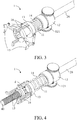
FIG. 3 is a schematic view in another perspective of the screw clamping device ofFIG. 1 ; -
FIG. 4 is a clamping schematic view of the screw clamping device ofFIG. 1 ; -
FIG. 5 is a schematic view of operation of the screw clamping device ofFIG. 1 ; -
FIG. 6 is a schematic view of operation of the screw clamping device ofFIG. 1 ; -
FIG. 7 is an unclamping schematic view of the screw clamping device ofFIG. 1 ; -
FIG. 8 is an expanded schematic view of a clamping unit of the screw clamping device ofFIG. 1 ; -
FIG. 9 is an expanded schematic view of the clamping unit of the screw clamping device ofFIG. 1 ; -
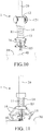
FIG. 10 is a restored schematic view of the screw clamping device ofFIG. 1 ; and -
FIG. 11 is a schematic view of the screw clamping device according to another embodiment of the present invention. - Implementation of the present invention is hereunder illustrated by specific embodiments. Persons skilled in the art can easily understand other advantages and effects of the present invention by referring to the disclosure contained in the specification.
- Referring to
FIG. 1 and FIG. 2 , there are a schematic view and an explode view respectively of ascrew clamping device 1 according to an embodiment of the present invention. As shown in the diagrams, thescrew clamping device 1 includes abody 11, afixing unit 12, apressing unit 13, aresilient unit 14, aclamping unit 15 and a connectingunit 16. Thebody 11 is a hollow-core cylinder. One end of thebody 11 has four dents d. The fixingunit 12 fits around thebody 11 and rotates relative to the body freely. The fixingunit 12 includes a plurality ofscrews 121 that penetrating the fixing unit12The pressing unit 13 is pressed against on thebody 11. Referring toFIG. 5 , an end of thepressing unit 13 is an L-shaped object and received in the dents d of thebody 11 for pressing against the surface of a workingobject 30. Theresilient unit 14 is disposed between the terminal portion of thebody 11 and thepressing unit 13. Referring toFIG. 4 , the clampingunit 15 is rotatably disposed on thebody 11 and received in the dents d of thebody 11. The clampingunit 15 includes two clamping arms which are symmetrically arranged thereon. Each clamping arm has one end in the form of a C-shaped object. Referring toFIG. 6 , the C-shaped objects are formed at the two clamping arms, respectively, obliquely in opposite directions. Therefore, to grip ascrew 40, the C-shaped objects of the clampingunit 15 slide into the head of thescrew 40 obliquely. With the C-shaped objects being formed at the two clamping arms obliquely in opposite directions, not only is it impossible for thescrew 40 to tilt in the course of the aforesaid process, but the C-shaped objects are also applicable toscrews 40 of different sizes. The connectingunit 16 has one end connected to thepressing unit 13 and the other end connected to theclamping unit 15. The connectingunit 16 drives the clampingunit 15 to rotate while the fixingunit 12 is moving axially. - Referring to
FIG. 3 through FIG. 10 , there are shown schematic views of operation of thescrew clamping device 1 according to the aforesaid embodiment of the present invention. As shown inFIG. 3 through FIG. 10 , thescrew clamping device 1 fits around ascrewdriver 20, thescrewdriver 20 penetrates thebody 11 and fixingunit 12 axially and is coupled to the fixingunit 12 throughscrews 121. Afterward, as shown inFIG. 5 , the intendedscrew 40 is placed at one end of thescrewdriver 20, and then both thescrewdriver 20 and thescrew 40 are moved to the workingobject 30. As shown inFIG. 6 , with thescrew 40 being clamped by the clampingunit 15 of thescrew clamping device 1, thescrew 40 is clamped and fixed to one end of thescrewdriver 20, allowing thescrew 40 to be driven into the workingobject 30 while being rotated by a user. As shown inFIG.7 , when thepressing unit 13 of thescrew clamping device 1 coming into contact with the working object, the fixingunit 12 is move down according to the rotation of thescrewdriver 20 and pressing the top of thebody 11 for moving down thebody 11. Simultaneously, the movements of the lower end of thebody 11 drives the clampingunit 15 to rotate. Therefore, the two C-shaped objects at the front ends of the clampingunit 15 are no longer clamping thescrew 40. As shown inFIG. 8 , in the situation where the user keeps driving thescrew 40 into the workingobject 30 by rotating thescrew 40, the rotation of thescrewdriver 20 causes thescrew 40 to be driven into the workingobject 30 but does not cause thebody 11 to rotate, because thebody 11 and the fixingunit 12 are movable. Thebody 11 compresses theresilient unit 14 and move downward along thescrewdriver 20; as a result, the connectingunit 16 drives the clampingunit 15 to rotate and stretch outward, thereby releasing thescrew 40. As shown inFIG. 9 , the clampingunit 15 is no longer clamping thescrew 40 after thescrew 40 has been driven into the workingobject 30. As shown inFIG. 10 , by contrast, thepressing unit 13 becomes a fixing end of theresilient unit 14 as soon as thescrew 40 is screwed in or out of the workingobject 30, and in consequence thebody 11 moves upward while restoration of the initial state of theresilient unit 14 is taking place; hence, again, the connectingunit 16 drives the clampingunit 15 to rotate and thereby restore or clamp thescrew 40. Therefore, thescrew clamping device 1 of the present invention prevents thescrew 40 from falling off or even getting missing while being loosened or tightened. Furthermore, thescrew clamping device 1 of the present invention can be coupled to thescrewdrivers 20 of different sizes to further broaden the application of thescrew clamping device 1. - Referring to
FIG. 11 , in another embodiment, the present invention dispenses with the fixingunit 12 as described below. The inner wall of thebody 11 is made of an elastic material, such as rubber. After penetrating thebody 11, thescrewdriver 20 stretches thebody 11 and thus is in tight contact with the inner wall of thebody 11. Owing to the friction between the inner wall and thescrewdriver 20, thescrewdriver 20 and thebody 11 are fixed to each other. - Given the aforesaid technical features of the
screw clamping device 1 of the present invention, thebody 11, theresilient unit 14, thepressing unit 13, the connectingunit 16 and theclamping unit 15 each rotate together with thescrewdriver 20. Thescrew clamping device 1 rotates about thescrew 40 without collisions, because thescrew 40 is located at the center of each of the two clampingunits 15. - As mentioned before, the present invention dispenses with the fixing
unit 12, thereby further simplifying the structure of thescrew clamping device 1.
Claims (6)
- A screw clamping device (1), comprising:a body (11) being a hollow-core cylinder, being subject to axial penetration of a screwdriver (20);a fixing unit (12) connected to the body (11) axially and fixed with the screwdriver (20), the fixing unit (12) being driven for pressing against the body (11) moved axially when the screwdriver (20) is rotating;a pressing unit (13) pressed against the body (11) and adapted to press against a surface of a working object (30);a resilient unit (14) disposed between the body (11) and the pressing unit;a clamping unit (15) rotatably connected to the body (11); anda connecting unit (16) with an end connected to the pressing unit (13) and another end connected to the clamping unit (15),wherein the connecting unit (16) drives the clamping unit (15) to rotate while the body (11) is moving axially.
- The screw clamping device (1) of claim 1, wherein the clamping unit (15) comprises at least a clamping arm with an end in a form of a C-shaped object.
- The screw clamping device (1) of claim 1, wherein an end of the pressing unit (13) comprises an L-shaped object.
- The screw clamping device (1) of claim 1, wherein an end of the body (11) comprises a plurality of dens (d) for receiving the pressing unit (13) and the clamping unit (15).
- The screw clamping device (1) of claim 1, wherein the fixing unit (12) comprises a plurality of screws (121) penetratingly disposed at the fixing unit (12) to press against the screwdriver (20).
- The screw clamping device (1) of claim 2, wherein the clamping arms are in number of two and symmetrically arranged on the clamping unit (15), with two said C-shaped objects formed at two said clamping arms, respectively, wherein the two C-shaped objects are oblique in opposite directions.
Applications Claiming Priority (1)
| Application Number | Priority Date | Filing Date | Title |
|---|---|---|---|
| TW106134568A TWI632031B (en) | 2017-10-06 | 2017-10-06 | Screw clamping device |
Publications (2)
| Publication Number | Publication Date |
|---|---|
| EP3482880A1 EP3482880A1 (en) | 2019-05-15 |
| EP3482880B1 true EP3482880B1 (en) | 2021-03-17 |
Family
ID=62530118
Family Applications (1)
| Application Number | Title | Priority Date | Filing Date |
|---|---|---|---|
| EP18175833.5A Active EP3482880B1 (en) | 2017-10-06 | 2018-06-04 | Screw clamping device |
Country Status (4)
| Country | Link |
|---|---|
| US (1) | US10906162B2 (en) |
| EP (1) | EP3482880B1 (en) |
| JP (1) | JP6886427B2 (en) |
| TW (1) | TWI632031B (en) |
Families Citing this family (6)
| Publication number | Priority date | Publication date | Assignee | Title |
|---|---|---|---|---|
| CN109396601B (en) * | 2018-12-13 | 2021-06-11 | 北京无线电测量研究所 | Welding auxiliary device of microstrip piece formula merit divider |
| US20200368884A1 (en) * | 2019-05-22 | 2020-11-26 | Robert Rivera | Screw Mount and Locking Device |
| CN111451972B (en) * | 2020-05-26 | 2021-06-29 | 广东电网有限责任公司东莞供电局 | removal tool |
| CN111872884A (en) * | 2020-08-24 | 2020-11-03 | 温州金三原工具有限公司 | Fastener holder |
| US12172269B2 (en) * | 2021-07-30 | 2024-12-24 | The Boeing Company | Fastener collar retainer |
| DE102023201572A1 (en) * | 2023-02-22 | 2024-08-22 | Adolf Würth GmbH & Co. KG | Screw support structure for a screwing tool and tool system |
Family Cites Families (28)
| Publication number | Priority date | Publication date | Assignee | Title |
|---|---|---|---|---|
| US1424703A (en) * | 1921-11-12 | 1922-08-01 | Joseph V Work | Screw-driver attachment |
| US1575149A (en) * | 1925-02-11 | 1926-03-02 | James L Craig | Screw holder and driver |
| US1779339A (en) * | 1929-07-09 | 1930-10-21 | Boris N Sokoloff | Screw driver |
| US2399138A (en) * | 1944-03-07 | 1946-04-23 | Nygaard Christ | Screw holding attachment for screw drivers |
| US2576742A (en) * | 1947-11-20 | 1951-11-27 | Wolny Joseph | Screw holding screw driver |
| DE1241380B (en) * | 1960-08-09 | 1967-05-24 | Alfred Schlotter | Tool for screwing in head screws, especially self-tapping self-tapping screws |
| US3965950A (en) * | 1975-03-20 | 1976-06-29 | Macdonald Murdo A | Fastener driver and fastener holding nosepiece |
| US3949795A (en) * | 1975-06-16 | 1976-04-13 | Hull Donald G | Sink clip inserting device |
| JPS5633278A (en) * | 1979-07-12 | 1981-04-03 | Okubo Seisakusho Kk | Driver |
| JPS6261473U (en) * | 1985-10-03 | 1987-04-16 | ||
| JPS6332769U (en) * | 1986-08-19 | 1988-03-02 | ||
| JPH02218563A (en) * | 1989-02-14 | 1990-08-31 | Toshiba Corp | Screw driver |
| JPH0539869U (en) * | 1991-10-31 | 1993-05-28 | 日新電機株式会社 | driver |
| JPH0711276U (en) * | 1993-07-26 | 1995-02-21 | 克成 杉山 | Screw catch jig for driver |
| US6244141B1 (en) * | 1998-08-10 | 2001-06-12 | Ki Su Han | Fastener holding device |
| CN2423067Y (en) * | 2000-01-21 | 2001-03-14 | 赖进财 | Socket holder structure for precision tools |
| US6314845B1 (en) * | 2000-02-24 | 2001-11-13 | Shu Te Wu | Clamp for screwed fastening member |
| TWM257929U (en) * | 2004-05-25 | 2005-03-01 | Mitac Int Corp | Auxiliary jig |
| US7069826B2 (en) * | 2004-10-08 | 2006-07-04 | Mike Tilton | Screwdriver attachment |
| DE102005000070A1 (en) * | 2005-05-30 | 2006-12-07 | Hilti Ag | Fastener feeding device for power driven tackers |
| JP2007222972A (en) * | 2006-02-22 | 2007-09-06 | Tokuo Miyashita | Bolt holder of screwdriver |
| WO2013026262A1 (en) * | 2011-08-20 | 2013-02-28 | 苏州宝时得电动工具有限公司 | Screw-supporting device and screwing tool |
| TW201436959A (en) * | 2013-03-29 | 2014-10-01 | Shou King Entpr Co Ltd | Screwdriver holder |
| CN104742068A (en) * | 2013-12-27 | 2015-07-01 | 富泰华工业(深圳)有限公司 | Screwdriver |
| KR20160010048A (en) * | 2014-07-18 | 2016-01-27 | 윤정운 | Manufacturing method of primer resin for optical pet film |
| KR20160100481A (en) * | 2015-02-14 | 2016-08-24 | 이진영 | Screw driver to prevent motion of the screw |
| TWI547352B (en) * | 2015-08-03 | 2016-09-01 | 仲展實業有限公司 | Clamping mechanism for fastening element and tool rod having the same |
| CN205703944U (en) * | 2016-06-23 | 2016-11-23 | 宁夏浩瑞斯机器人科技有限公司 | A kind of screw locking machine jaw head unit |
-
2017
- 2017-10-06 TW TW106134568A patent/TWI632031B/en active
-
2018
- 2018-01-18 US US15/874,073 patent/US10906162B2/en active Active
- 2018-04-09 JP JP2018074556A patent/JP6886427B2/en active Active
- 2018-06-04 EP EP18175833.5A patent/EP3482880B1/en active Active
Non-Patent Citations (1)
| Title |
|---|
| None * |
Also Published As
| Publication number | Publication date |
|---|---|
| TW201914766A (en) | 2019-04-16 |
| US10906162B2 (en) | 2021-02-02 |
| US20190105763A1 (en) | 2019-04-11 |
| JP2019069504A (en) | 2019-05-09 |
| EP3482880A1 (en) | 2019-05-15 |
| TWI632031B (en) | 2018-08-11 |
| JP6886427B2 (en) | 2021-06-16 |
Similar Documents
| Publication | Publication Date | Title |
|---|---|---|
| EP3482880A1 (en) | Screw clamping device | |
| CN1034318C (en) | Quick-action clamps | |
| CN109128917B (en) | Self-adaptive adjustable clamp for processing aluminum products | |
| US9316240B2 (en) | Clamping assembly | |
| US2916812A (en) | Coupling inserting apparatus | |
| CN110405009B (en) | A sheet metal processing device | |
| US20150040366A1 (en) | Apparatus for inserting a hose coupling into a hose | |
| JP5872519B2 (en) | Ratchet tool for indirect hot wire work | |
| US10295322B1 (en) | Stuck ammunition shell remover | |
| KR20080005647U (en) | Portable pipe expander | |
| CN104139368B (en) | Ring elastic parts mounting tool and device for spreading thereof | |
| CN218402850U (en) | Unreeling machine capable of clamping side wall of steel coil | |
| CN105058098A (en) | Screw drive type clamp | |
| CN216464333U (en) | Dismantle frock and robot | |
| CN115056141A (en) | Clamping device suitable for multi-size shaft rod type workpieces | |
| JP2000237832A (en) | Method and device for expanding metal tube | |
| CN208714148U (en) | It is a kind of for processing the hole punched device in luggage handle hole | |
| CN223693575U (en) | Clamping mechanism and threading device | |
| CN111633598A (en) | Solid wrench | |
| CN1483541A (en) | Power clamping drill chuck | |
| CN223160769U (en) | Pressure-reducing flat tongs for granary groove pressing pipe | |
| CN204868166U (en) | Screw rod drive formula anchor clamps | |
| CN214292401U (en) | Grinding machine clamping and fixing mechanism for bearing | |
| CN205763280U (en) | Upper die of bending machine tool fast fixture | |
| CN217045523U (en) | Side locking clamp |
Legal Events
| Date | Code | Title | Description |
|---|---|---|---|
| PUAI | Public reference made under article 153(3) epc to a published international application that has entered the european phase |
Free format text: ORIGINAL CODE: 0009012 |
|
| STAA | Information on the status of an ep patent application or granted ep patent |
Free format text: STATUS: THE APPLICATION HAS BEEN PUBLISHED |
|
| AK | Designated contracting states |
Kind code of ref document: A1 Designated state(s): AL AT BE BG CH CY CZ DE DK EE ES FI FR GB GR HR HU IE IS IT LI LT LU LV MC MK MT NL NO PL PT RO RS SE SI SK SM TR |
|
| AX | Request for extension of the european patent |
Extension state: BA ME |
|
| STAA | Information on the status of an ep patent application or granted ep patent |
Free format text: STATUS: REQUEST FOR EXAMINATION WAS MADE |
|
| 17P | Request for examination filed |
Effective date: 20190724 |
|
| RBV | Designated contracting states (corrected) |
Designated state(s): AL AT BE BG CH CY CZ DE DK EE ES FI FR GB GR HR HU IE IS IT LI LT LU LV MC MK MT NL NO PL PT RO RS SE SI SK SM TR |
|
| GRAP | Despatch of communication of intention to grant a patent |
Free format text: ORIGINAL CODE: EPIDOSNIGR1 |
|
| STAA | Information on the status of an ep patent application or granted ep patent |
Free format text: STATUS: GRANT OF PATENT IS INTENDED |
|
| INTG | Intention to grant announced |
Effective date: 20201113 |
|
| GRAS | Grant fee paid |
Free format text: ORIGINAL CODE: EPIDOSNIGR3 |
|
| GRAA | (expected) grant |
Free format text: ORIGINAL CODE: 0009210 |
|
| STAA | Information on the status of an ep patent application or granted ep patent |
Free format text: STATUS: THE PATENT HAS BEEN GRANTED |
|
| AK | Designated contracting states |
Kind code of ref document: B1 Designated state(s): AL AT BE BG CH CY CZ DE DK EE ES FI FR GB GR HR HU IE IS IT LI LT LU LV MC MK MT NL NO PL PT RO RS SE SI SK SM TR |
|
| REG | Reference to a national code |
Ref country code: GB Ref legal event code: FG4D |
|
| REG | Reference to a national code |
Ref country code: CH Ref legal event code: EP |
|
| REG | Reference to a national code |
Ref country code: DE Ref legal event code: R096 Ref document number: 602018013934 Country of ref document: DE |
|
| REG | Reference to a national code |
Ref country code: IE Ref legal event code: FG4D |
|
| REG | Reference to a national code |
Ref country code: AT Ref legal event code: REF Ref document number: 1371804 Country of ref document: AT Kind code of ref document: T Effective date: 20210415 |
|
| REG | Reference to a national code |
Ref country code: LT Ref legal event code: MG9D |
|
| PG25 | Lapsed in a contracting state [announced via postgrant information from national office to epo] |
Ref country code: NO Free format text: LAPSE BECAUSE OF FAILURE TO SUBMIT A TRANSLATION OF THE DESCRIPTION OR TO PAY THE FEE WITHIN THE PRESCRIBED TIME-LIMIT Effective date: 20210617 Ref country code: GR Free format text: LAPSE BECAUSE OF FAILURE TO SUBMIT A TRANSLATION OF THE DESCRIPTION OR TO PAY THE FEE WITHIN THE PRESCRIBED TIME-LIMIT Effective date: 20210618 Ref country code: HR Free format text: LAPSE BECAUSE OF FAILURE TO SUBMIT A TRANSLATION OF THE DESCRIPTION OR TO PAY THE FEE WITHIN THE PRESCRIBED TIME-LIMIT Effective date: 20210317 Ref country code: FI Free format text: LAPSE BECAUSE OF FAILURE TO SUBMIT A TRANSLATION OF THE DESCRIPTION OR TO PAY THE FEE WITHIN THE PRESCRIBED TIME-LIMIT Effective date: 20210317 Ref country code: BG Free format text: LAPSE BECAUSE OF FAILURE TO SUBMIT A TRANSLATION OF THE DESCRIPTION OR TO PAY THE FEE WITHIN THE PRESCRIBED TIME-LIMIT Effective date: 20210617 |
|
| REG | Reference to a national code |
Ref country code: AT Ref legal event code: MK05 Ref document number: 1371804 Country of ref document: AT Kind code of ref document: T Effective date: 20210317 |
|
| REG | Reference to a national code |
Ref country code: NL Ref legal event code: MP Effective date: 20210317 |
|
| PG25 | Lapsed in a contracting state [announced via postgrant information from national office to epo] |
Ref country code: RS Free format text: LAPSE BECAUSE OF FAILURE TO SUBMIT A TRANSLATION OF THE DESCRIPTION OR TO PAY THE FEE WITHIN THE PRESCRIBED TIME-LIMIT Effective date: 20210317 Ref country code: LV Free format text: LAPSE BECAUSE OF FAILURE TO SUBMIT A TRANSLATION OF THE DESCRIPTION OR TO PAY THE FEE WITHIN THE PRESCRIBED TIME-LIMIT Effective date: 20210317 Ref country code: SE Free format text: LAPSE BECAUSE OF FAILURE TO SUBMIT A TRANSLATION OF THE DESCRIPTION OR TO PAY THE FEE WITHIN THE PRESCRIBED TIME-LIMIT Effective date: 20210317 |
|
| PG25 | Lapsed in a contracting state [announced via postgrant information from national office to epo] |
Ref country code: NL Free format text: LAPSE BECAUSE OF FAILURE TO SUBMIT A TRANSLATION OF THE DESCRIPTION OR TO PAY THE FEE WITHIN THE PRESCRIBED TIME-LIMIT Effective date: 20210317 |
|
| PG25 | Lapsed in a contracting state [announced via postgrant information from national office to epo] |
Ref country code: LT Free format text: LAPSE BECAUSE OF FAILURE TO SUBMIT A TRANSLATION OF THE DESCRIPTION OR TO PAY THE FEE WITHIN THE PRESCRIBED TIME-LIMIT Effective date: 20210317 Ref country code: CZ Free format text: LAPSE BECAUSE OF FAILURE TO SUBMIT A TRANSLATION OF THE DESCRIPTION OR TO PAY THE FEE WITHIN THE PRESCRIBED TIME-LIMIT Effective date: 20210317 Ref country code: EE Free format text: LAPSE BECAUSE OF FAILURE TO SUBMIT A TRANSLATION OF THE DESCRIPTION OR TO PAY THE FEE WITHIN THE PRESCRIBED TIME-LIMIT Effective date: 20210317 Ref country code: AT Free format text: LAPSE BECAUSE OF FAILURE TO SUBMIT A TRANSLATION OF THE DESCRIPTION OR TO PAY THE FEE WITHIN THE PRESCRIBED TIME-LIMIT Effective date: 20210317 Ref country code: SM Free format text: LAPSE BECAUSE OF FAILURE TO SUBMIT A TRANSLATION OF THE DESCRIPTION OR TO PAY THE FEE WITHIN THE PRESCRIBED TIME-LIMIT Effective date: 20210317 |
|
| PG25 | Lapsed in a contracting state [announced via postgrant information from national office to epo] |
Ref country code: RO Free format text: LAPSE BECAUSE OF FAILURE TO SUBMIT A TRANSLATION OF THE DESCRIPTION OR TO PAY THE FEE WITHIN THE PRESCRIBED TIME-LIMIT Effective date: 20210317 Ref country code: SK Free format text: LAPSE BECAUSE OF FAILURE TO SUBMIT A TRANSLATION OF THE DESCRIPTION OR TO PAY THE FEE WITHIN THE PRESCRIBED TIME-LIMIT Effective date: 20210317 Ref country code: PT Free format text: LAPSE BECAUSE OF FAILURE TO SUBMIT A TRANSLATION OF THE DESCRIPTION OR TO PAY THE FEE WITHIN THE PRESCRIBED TIME-LIMIT Effective date: 20210719 Ref country code: PL Free format text: LAPSE BECAUSE OF FAILURE TO SUBMIT A TRANSLATION OF THE DESCRIPTION OR TO PAY THE FEE WITHIN THE PRESCRIBED TIME-LIMIT Effective date: 20210317 Ref country code: IS Free format text: LAPSE BECAUSE OF FAILURE TO SUBMIT A TRANSLATION OF THE DESCRIPTION OR TO PAY THE FEE WITHIN THE PRESCRIBED TIME-LIMIT Effective date: 20210717 |
|
| REG | Reference to a national code |
Ref country code: DE Ref legal event code: R097 Ref document number: 602018013934 Country of ref document: DE |
|
| PLBE | No opposition filed within time limit |
Free format text: ORIGINAL CODE: 0009261 |
|
| STAA | Information on the status of an ep patent application or granted ep patent |
Free format text: STATUS: NO OPPOSITION FILED WITHIN TIME LIMIT |
|
| PG25 | Lapsed in a contracting state [announced via postgrant information from national office to epo] |
Ref country code: MC Free format text: LAPSE BECAUSE OF FAILURE TO SUBMIT A TRANSLATION OF THE DESCRIPTION OR TO PAY THE FEE WITHIN THE PRESCRIBED TIME-LIMIT Effective date: 20210317 Ref country code: DK Free format text: LAPSE BECAUSE OF FAILURE TO SUBMIT A TRANSLATION OF THE DESCRIPTION OR TO PAY THE FEE WITHIN THE PRESCRIBED TIME-LIMIT Effective date: 20210317 Ref country code: AL Free format text: LAPSE BECAUSE OF FAILURE TO SUBMIT A TRANSLATION OF THE DESCRIPTION OR TO PAY THE FEE WITHIN THE PRESCRIBED TIME-LIMIT Effective date: 20210317 Ref country code: ES Free format text: LAPSE BECAUSE OF FAILURE TO SUBMIT A TRANSLATION OF THE DESCRIPTION OR TO PAY THE FEE WITHIN THE PRESCRIBED TIME-LIMIT Effective date: 20210317 |
|
| REG | Reference to a national code |
Ref country code: CH Ref legal event code: PL |
|
| 26N | No opposition filed |
Effective date: 20211220 |
|
| PG25 | Lapsed in a contracting state [announced via postgrant information from national office to epo] |
Ref country code: SI Free format text: LAPSE BECAUSE OF FAILURE TO SUBMIT A TRANSLATION OF THE DESCRIPTION OR TO PAY THE FEE WITHIN THE PRESCRIBED TIME-LIMIT Effective date: 20210317 |
|
| REG | Reference to a national code |
Ref country code: BE Ref legal event code: MM Effective date: 20210630 |
|
| PG25 | Lapsed in a contracting state [announced via postgrant information from national office to epo] |
Ref country code: LU Free format text: LAPSE BECAUSE OF NON-PAYMENT OF DUE FEES Effective date: 20210604 |
|
| PG25 | Lapsed in a contracting state [announced via postgrant information from national office to epo] |
Ref country code: LI Free format text: LAPSE BECAUSE OF NON-PAYMENT OF DUE FEES Effective date: 20210630 Ref country code: IT Free format text: LAPSE BECAUSE OF FAILURE TO SUBMIT A TRANSLATION OF THE DESCRIPTION OR TO PAY THE FEE WITHIN THE PRESCRIBED TIME-LIMIT Effective date: 20210317 Ref country code: IE Free format text: LAPSE BECAUSE OF NON-PAYMENT OF DUE FEES Effective date: 20210604 Ref country code: CH Free format text: LAPSE BECAUSE OF NON-PAYMENT OF DUE FEES Effective date: 20210630 |
|
| PG25 | Lapsed in a contracting state [announced via postgrant information from national office to epo] |
Ref country code: IS Free format text: LAPSE BECAUSE OF FAILURE TO SUBMIT A TRANSLATION OF THE DESCRIPTION OR TO PAY THE FEE WITHIN THE PRESCRIBED TIME-LIMIT Effective date: 20210717 |
|
| PG25 | Lapsed in a contracting state [announced via postgrant information from national office to epo] |
Ref country code: BE Free format text: LAPSE BECAUSE OF NON-PAYMENT OF DUE FEES Effective date: 20210630 |
|
| PG25 | Lapsed in a contracting state [announced via postgrant information from national office to epo] |
Ref country code: CY Free format text: LAPSE BECAUSE OF FAILURE TO SUBMIT A TRANSLATION OF THE DESCRIPTION OR TO PAY THE FEE WITHIN THE PRESCRIBED TIME-LIMIT Effective date: 20210317 |
|
| PG25 | Lapsed in a contracting state [announced via postgrant information from national office to epo] |
Ref country code: HU Free format text: LAPSE BECAUSE OF FAILURE TO SUBMIT A TRANSLATION OF THE DESCRIPTION OR TO PAY THE FEE WITHIN THE PRESCRIBED TIME-LIMIT; INVALID AB INITIO Effective date: 20180604 |
|
| PG25 | Lapsed in a contracting state [announced via postgrant information from national office to epo] |
Ref country code: MK Free format text: LAPSE BECAUSE OF FAILURE TO SUBMIT A TRANSLATION OF THE DESCRIPTION OR TO PAY THE FEE WITHIN THE PRESCRIBED TIME-LIMIT Effective date: 20210317 |
|
| PG25 | Lapsed in a contracting state [announced via postgrant information from national office to epo] |
Ref country code: MT Free format text: LAPSE BECAUSE OF FAILURE TO SUBMIT A TRANSLATION OF THE DESCRIPTION OR TO PAY THE FEE WITHIN THE PRESCRIBED TIME-LIMIT Effective date: 20210317 |
|
| PGFP | Annual fee paid to national office [announced via postgrant information from national office to epo] |
Ref country code: DE Payment date: 20250401 Year of fee payment: 8 |
|
| PGFP | Annual fee paid to national office [announced via postgrant information from national office to epo] |
Ref country code: GB Payment date: 20250401 Year of fee payment: 8 |
|
| PGFP | Annual fee paid to national office [announced via postgrant information from national office to epo] |
Ref country code: FR Payment date: 20250401 Year of fee payment: 8 |
|
| PG25 | Lapsed in a contracting state [announced via postgrant information from national office to epo] |
Ref country code: TR Free format text: LAPSE BECAUSE OF FAILURE TO SUBMIT A TRANSLATION OF THE DESCRIPTION OR TO PAY THE FEE WITHIN THE PRESCRIBED TIME-LIMIT Effective date: 20210317 |