EP3482848A1 - Multi-layer susceptor design for magnetic flux shielding in directional solidification furnaces - Google Patents
Multi-layer susceptor design for magnetic flux shielding in directional solidification furnaces Download PDFInfo
- Publication number
- EP3482848A1 EP3482848A1 EP18203516.2A EP18203516A EP3482848A1 EP 3482848 A1 EP3482848 A1 EP 3482848A1 EP 18203516 A EP18203516 A EP 18203516A EP 3482848 A1 EP3482848 A1 EP 3482848A1
- Authority
- EP
- European Patent Office
- Prior art keywords
- layer
- electromagnetic field
- susceptor
- mold
- chamber
- Prior art date
- Legal status (The legal status is an assumption and is not a legal conclusion. Google has not performed a legal analysis and makes no representation as to the accuracy of the status listed.)
- Granted
Links
Images
Classifications
-
- C—CHEMISTRY; METALLURGY
- C30—CRYSTAL GROWTH
- C30B—SINGLE-CRYSTAL GROWTH; UNIDIRECTIONAL SOLIDIFICATION OF EUTECTIC MATERIAL OR UNIDIRECTIONAL DEMIXING OF EUTECTOID MATERIAL; REFINING BY ZONE-MELTING OF MATERIAL; PRODUCTION OF A HOMOGENEOUS POLYCRYSTALLINE MATERIAL WITH DEFINED STRUCTURE; SINGLE CRYSTALS OR HOMOGENEOUS POLYCRYSTALLINE MATERIAL WITH DEFINED STRUCTURE; AFTER-TREATMENT OF SINGLE CRYSTALS OR A HOMOGENEOUS POLYCRYSTALLINE MATERIAL WITH DEFINED STRUCTURE; APPARATUS THEREFOR
- C30B11/00—Single-crystal growth by normal freezing or freezing under temperature gradient, e.g. Bridgman-Stockbarger method
- C30B11/003—Heating or cooling of the melt or the crystallised material
-
- B—PERFORMING OPERATIONS; TRANSPORTING
- B22—CASTING; POWDER METALLURGY
- B22D—CASTING OF METALS; CASTING OF OTHER SUBSTANCES BY THE SAME PROCESSES OR DEVICES
- B22D27/00—Treating the metal in the mould while it is molten or ductile ; Pressure or vacuum casting
- B22D27/02—Use of electric or magnetic effects
-
- B—PERFORMING OPERATIONS; TRANSPORTING
- B22—CASTING; POWDER METALLURGY
- B22D—CASTING OF METALS; CASTING OF OTHER SUBSTANCES BY THE SAME PROCESSES OR DEVICES
- B22D27/00—Treating the metal in the mould while it is molten or ductile ; Pressure or vacuum casting
- B22D27/04—Influencing the temperature of the metal, e.g. by heating or cooling the mould
- B22D27/045—Directionally solidified castings
-
- C—CHEMISTRY; METALLURGY
- C30—CRYSTAL GROWTH
- C30B—SINGLE-CRYSTAL GROWTH; UNIDIRECTIONAL SOLIDIFICATION OF EUTECTIC MATERIAL OR UNIDIRECTIONAL DEMIXING OF EUTECTOID MATERIAL; REFINING BY ZONE-MELTING OF MATERIAL; PRODUCTION OF A HOMOGENEOUS POLYCRYSTALLINE MATERIAL WITH DEFINED STRUCTURE; SINGLE CRYSTALS OR HOMOGENEOUS POLYCRYSTALLINE MATERIAL WITH DEFINED STRUCTURE; AFTER-TREATMENT OF SINGLE CRYSTALS OR A HOMOGENEOUS POLYCRYSTALLINE MATERIAL WITH DEFINED STRUCTURE; APPARATUS THEREFOR
- C30B11/00—Single-crystal growth by normal freezing or freezing under temperature gradient, e.g. Bridgman-Stockbarger method
- C30B11/002—Crucibles or containers for supporting the melt
-
- F—MECHANICAL ENGINEERING; LIGHTING; HEATING; WEAPONS; BLASTING
- F27—FURNACES; KILNS; OVENS; RETORTS
- F27B—FURNACES, KILNS, OVENS OR RETORTS IN GENERAL; OPEN SINTERING OR LIKE APPARATUS
- F27B14/00—Crucible or pot furnaces
- F27B14/06—Crucible or pot furnaces heated electrically, e.g. induction crucible furnaces with or without any other source of heat
- F27B14/061—Induction furnaces
-
- F—MECHANICAL ENGINEERING; LIGHTING; HEATING; WEAPONS; BLASTING
- F27—FURNACES; KILNS; OVENS; RETORTS
- F27B—FURNACES, KILNS, OVENS OR RETORTS IN GENERAL; OPEN SINTERING OR LIKE APPARATUS
- F27B14/00—Crucible or pot furnaces
- F27B14/08—Details specially adapted for crucible or pot furnaces
- F27B14/14—Arrangements of heating devices
-
- F—MECHANICAL ENGINEERING; LIGHTING; HEATING; WEAPONS; BLASTING
- F27—FURNACES; KILNS; OVENS; RETORTS
- F27D—DETAILS OR ACCESSORIES OF FURNACES, KILNS, OVENS OR RETORTS, IN SO FAR AS THEY ARE OF KINDS OCCURRING IN MORE THAN ONE KIND OF FURNACE
- F27D11/00—Arrangement of elements for electric heating in or on furnaces
- F27D11/06—Induction heating, i.e. in which the material being heated, or its container or elements embodied therein, form the secondary of a transformer
-
- H—ELECTRICITY
- H05—ELECTRIC TECHNIQUES NOT OTHERWISE PROVIDED FOR
- H05B—ELECTRIC HEATING; ELECTRIC LIGHT SOURCES NOT OTHERWISE PROVIDED FOR; CIRCUIT ARRANGEMENTS FOR ELECTRIC LIGHT SOURCES, IN GENERAL
- H05B6/00—Heating by electric, magnetic or electromagnetic fields
- H05B6/02—Induction heating
- H05B6/10—Induction heating apparatus, other than furnaces, for specific applications
- H05B6/105—Induction heating apparatus, other than furnaces, for specific applications using a susceptor
-
- H—ELECTRICITY
- H05—ELECTRIC TECHNIQUES NOT OTHERWISE PROVIDED FOR
- H05B—ELECTRIC HEATING; ELECTRIC LIGHT SOURCES NOT OTHERWISE PROVIDED FOR; CIRCUIT ARRANGEMENTS FOR ELECTRIC LIGHT SOURCES, IN GENERAL
- H05B6/00—Heating by electric, magnetic or electromagnetic fields
- H05B6/02—Induction heating
- H05B6/22—Furnaces without an endless core
- H05B6/24—Crucible furnaces
- H05B6/28—Protective systems
-
- H—ELECTRICITY
- H05—ELECTRIC TECHNIQUES NOT OTHERWISE PROVIDED FOR
- H05B—ELECTRIC HEATING; ELECTRIC LIGHT SOURCES NOT OTHERWISE PROVIDED FOR; CIRCUIT ARRANGEMENTS FOR ELECTRIC LIGHT SOURCES, IN GENERAL
- H05B6/00—Heating by electric, magnetic or electromagnetic fields
- H05B6/02—Induction heating
- H05B6/36—Coil arrangements
- H05B6/367—Coil arrangements for melting furnaces
Definitions
- the present disclosure is directed to a device for directional solidification of a cast part. More particularly, this disclosure relates to a directional solidification casting device that controls a magnetic field to provide a desired microstructure.
- a directional solidification (DS) casting process is utilized to orient crystal structure within a cast part.
- the desired orientation is provided by moving a mold from a hot zone within a furnace into a cooler zone at a desired rate. As the mold moves into the cooler zone, the molten material solidifies along a solidification front traveling in one direction.
- Mixing of the molten material at the solidification front within the cast component is known to be deleterious to the quality of single crystal castings.
- Such mixing can be induced in the molten metal material by a magnetic field generated from an energized coil encircling the furnace cavity.
- an induction withdrawal furnace utilizes such an electric coil that produces energy required for maintaining the metal in a molten state.
- a susceptor is utilized to transduce an electromagnetic field produced by the electric coil into radiant heat transferred to the casting mold.
- the susceptor is usually a monolithic graphite cylinder located internal to the induction coil and external to the mold.
- the susceptor is heated by induction coils and radiates heat toward the mold to maintain metal in a molten state, and is intended to isolate the electromagnetic field from the hot zone of the furnace.
- the susceptor therefore fulfills two roles: it transduces the electromagnetic field from the primary induction coil into heat, and simultaneously attenuates said field.
- Casting single crystal gas turbine parts can experience less than 100% yields.
- Some defects that occur during the casting process are separately nucleated grains, freckels, porosity, mis-oriented boundaries, and others.
- the causes of these defects are not always known, but have been empirically determined to be influenced by the geometry of the part and the relative orientation of the part and the mold in the furnace. It is hypothesized that remnant magnetic field in the interior of the susceptor may be detrimental to the production of the desired microstructure in a cast part. Calculations have been made estimating the significance for a given production furnace design. For a monolithic graphite susceptor, the thickness required to fully attenuate said electromagnetic field may be impractical for design and/or production considerations.
- a process for directional solidification of a cast part comprising energizing a primary induction coil coupled to a chamber having a mold containing a casting material generating an electromagnetic field with the primary inductive coil within the chamber, a susceptor is coupled to the chamber between the primary induction coil and the mold; transducing at least a portion of the electromagnetic field into heat energy used to heat the mold; attenuating at least a portion of the electromagnetic field with the susceptor, wherein the susceptor comprises at least two layers of electromagnetic shield material; and casting the material within the mold.
- the layered susceptor material system comprises a constant thickness for each of the at least two layers.
- the at least two layers of electromagnetic shield material attenuate the primary induction coil electromagnetic field away from the mold.
- the susceptor comprises a first layer and a second layer enclosing an interior layer which may act to protect the interior layer from material degradation.
- the electromagnetic field shield materials of each of the first layer, second layer and the interior layer are responsive to a capacity as an electromagnetic shield.
- the layered susceptor acts to attenuate a total electromagnetic field emitted by the primary induction coil in order to provide a directional solidification casting process in the total or partial absence of a magnetic flux.
- the electromagnetic field shield materials can be selected for attenuation of the electromagnetic field at different temperature ranges used in casting different material alloys.
- an induction furnace assembly comprising a chamber having a mold; a primary inductive coil coupled to the chamber; and a susceptor comprising at least two layers of electromagnetic field attenuating material surrounding the chamber between the primary inductive coil and the mold.
- the at least two layers of electromagnetic field attenuating material are configured to attenuate the primary induction coil electromagnetic field away from the mold.
- the susceptor comprises a first layer and a second layer enclosing an interior layer.
- the first layer and the second layer comprise the same material.
- the electromagnetic field attenuating materials holistically comprise a primary means for transducing the electromagnetic field from the primary induction coil into heat, and simultaneously attenuating the field controlling the magnetic flux leakage perceived by the mold.
- the system of electromagnetic field attenuating materials each comprise material properties configured to attenuate the primary induction coil electromagnetic field at predetermined casting temperatures.
- the first layer and the second layer comprise a ceramic material.
- the first layer and the second layer comprise a refractory material.
- the first layer and the second layer comprise a graphite material.
- the first layer and the second layer each comprise material properties configured to attenuate the primary induction coil electromagnetic field at predetermined casting temperatures.
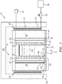
- FIG. 1 is a schematic illustration of an exemplary inductive furnace with an exemplary layered susceptor disposed within the furnace.
- an exemplary induction furnace assembly 10 includes a chamber 12 that includes an opening 14 through which a mold 16 is received and withdrawn.
- the chamber 12 is isolated from the external environment by insulated walls 18.
- the furnace chamber 12 can operate at near vacuum or under vacuum.
- a primary inductive coil 20 generates an electromagnetic field 28. This electromagnetic field 28 is transduced by a layered susceptor into heat. Heat, indicated by arrows 22, serves to heat a material 24 within the mold 16 to a desired temperature.
- the exemplary furnace assembly 10 includes a susceptor 26 that partially absorbs the electromagnetic field (schematically shown at 28) that is generated by the primary induction coil 20.
- the susceptor 26 is a wall that surrounds the chamber 12.
- the susceptor 26 is fabricated from material, such as graphite, that absorbs the electromagnetic field 28 produced by the primary induction coil 20.
- the susceptor 26 can also provide for the translation of energy from the electromagnetic field into heat energy, as indicated at arrows 22 to further maintain a temperature within the mold 16.
- molten metal material 24 is disposed in the mold 16 which in turn is supported on a support 30.
- the support 30 includes a chill plate 32 that both supports the mold 16 and includes cooling features to aid in cooling the molten material 24.
- the primary induction coil 20 receives electrical energy from an electric power source schematically indicated at 34. This electrical energy is provided at a desired current level determined to provide sufficient power and energy to create the desired temperature within the chamber 12 that maintains the metal 24 in a molten state.
- the primary induction coil 20 comprises a plurality of electrically conductive hollow tubes 35.
- the plurality of tubes 35 also provide for the circulation of a fluid that is generated by a pump 36 that supplies fluid from a fluid source 38 to flow through the tubes 35.
- the furnace 10 is brought up to a desired temperature by providing a sufficient current from the electric power source 34 to the primary induction coil 20. Water supplied from the pump 36 and fluid source 38 is pumped through the plurality of tubes 35 that make up the induction coil 20.
- the furnace chamber 12 can be under a vacuum or near vacuum, to support proper casting.
- the heat 22 created by the partial conversion of the electromagnetic field by the susceptor 26 heats the core furnace zone in the chamber 12 to a desired temperature. Once a desired temperature is reached, molten material, metal 24 is poured into the mold 16.
- the mold 16 defines the external shape and features of the completed cast article.
- the material 24 is maintained at a desired temperature in a molten state.
- the support 30 is then lowered from the opening 14 out of the hot chamber 12 through a baffle.
- the mold 16 is lowered from the chamber 12 at a desired rate to cool the molten material 24 in a controlled manner to produce desired columnar structure or single crystal.
- the controlled cooling produces a solidification front within the molten material 24.
- the completed cast part is desired to include a specific grain structure.
- the orientation, and structure of grains within the completed cast part provide desired material characteristics and performance, such as for example, material fatigue performance.
- the exemplary furnace assembly 10 includes the susceptor 26 with a constant thickness.
- the component of the electromagnetic field 28 that leaks beyond the susceptor, that is magnetic flux leakage, generates a certain amount of inductive stirring within the molten metal material 24.
- the generated electromagnetic field 28 not absorbed by the susceptor has a potential to produce currents within the molten metal material 24 that interact with the molten metal material 24 to provide stirring which may in turn, negatively impact the formation of the desired microstructure, such as inhibit defect-free single crystal growth.
- the susceptor 26 is sized to include a thickness that is thick enough to shield the electromagnetic field within the hot zone of the chamber 12.
- This electromagnetic field leakage that is magnetic flux leakage 42, may be unwanted and detrimental to proper grain structure formation.
- the exemplary susceptor 26 includes at least two layers 40 configured to attenuate the electromagnetic field 28 that radiates to the susceptor 26.
- the at least two layers 40 can comprise a layered susceptor material system 40.
- the electromagnetic field that passes the susceptor 26 is magnetic flux leakage 42 or simply magnetic flux 42.
- the susceptor 26 can contain at least two layers of different material 44 that further attenuates the primary induction coil 20 electromagnetic field 28.
- the layers 40 of material 44 in the susceptor can be tailored depending on the electromagnetic field 28 at predetermined locations, such as proximate the mold 16, within the chamber 12, within the mold 16, and the like.
- the magnetic flux leakage or simply magnetic flux 42 can include the portions of the electromagnetic field 28 passing into the mold 16 that are not attenuated by the susceptor 26.
- the susceptor 26 with layers 40 can be placed between the casting material 24 in the mold 16 and the primary inductive coil 20.
- the multi-layered susceptor 26 can act as a means for controlling the leaked electromagnetic field or attenuator 46.
- the material 44 of each layer 40 can be selected for its capacity as an electromagnetic shield 46 for the magnetic stirring caused by the electromagnetic flux 42.
- the shield material 44 can include properties to attenuate the electromagnetic field 28 at the casting temperatures. Different shield materials 44 can be selected for casting different casting material 24 alloys in predetermined temperature ranges.
- the shield material 44 can be selected for the magnetic permeability and high magnetic Curie point, for example, cobalt. In this way stirring can be better controlled within the molten material.
- the utilization of the shield material 44 as disclosed can reduce grain defects in single crystal castings.
- the susceptor 26 can include three layers 40.
- An interior layer 48 can comprise a cobalt material.
- a first layer 50 can be coupled to the interior layer 48 on a first side 52.
- the first layer 50 can comprise a graphite material.
- a second layer 54 can be coupled to the interior layer 48 on a second side 56 opposite the first side 52.
- the second layer 54 can comprise a graphite material.
- the first layer 50 and second layer 54 can comprise the same material.
- the first layer 50 and second layer 54 can comprise a ceramic material.
- the first layer 50 and second layer 54 can comprise a refractory material or a thermal barrier coating material.
- the layers 40 can be configured with the first layer 50 and second layer 54 enclosing the interior layer 48 to protect the interior layer from degradation.
- interior layer 48 used for attenuation of field should be made of a metal.
- the shield material 44 and/or the interior layer 48 can comprise at least one of a castable Nickel-based or Co-based superalloy, castable ferrous alloys and the like.
- the shield material 44 can comprise pure metals, cobalt, iron, copper, nickel, and the like.
- the shield material 44 can comprise conductive or magnetic ceramic material.
- the shield material 44 can be an alloy composed of W, Ta, V, Mo and/or Nb in some mixture. Choice of shield material 44 will be influenced by both a desired furnace operating temperature and a required degree of attenuation.
- the thickness T of the susceptor layers 40 can be varied to control the amount of magnetic flux 42 into the mold 16.
- thickness of a monolithic graphite susceptor layer 50 is nominally 0.75 inch (19.05mm).
- the first and second layers 50, 54 can have a thicknesses of from about 0.1 inch (2.54mm) to 1 inch (25.4mm).
- the interior 48 can be less than about 1 inch (25.4mm) in thickness.
- the interior 48 can be thinner than the first and second layers 50, 54.
- the size and shape of the exemplary susceptor 26 can be tailored to control the magnetic stirring.
Landscapes
- Engineering & Computer Science (AREA)
- Mechanical Engineering (AREA)
- General Engineering & Computer Science (AREA)
- Chemical & Material Sciences (AREA)
- Physics & Mathematics (AREA)
- Electromagnetism (AREA)
- Crystallography & Structural Chemistry (AREA)
- Materials Engineering (AREA)
- Metallurgy (AREA)
- Organic Chemistry (AREA)
- Power Engineering (AREA)
- Furnace Details (AREA)
Abstract
Description
- The present disclosure is directed to a device for directional solidification of a cast part. More particularly, this disclosure relates to a directional solidification casting device that controls a magnetic field to provide a desired microstructure.
- A directional solidification (DS) casting process is utilized to orient crystal structure within a cast part. The desired orientation is provided by moving a mold from a hot zone within a furnace into a cooler zone at a desired rate. As the mold moves into the cooler zone, the molten material solidifies along a solidification front traveling in one direction.
- Mixing of the molten material at the solidification front within the cast component is known to be deleterious to the quality of single crystal castings. Such mixing can be induced in the molten metal material by a magnetic field generated from an energized coil encircling the furnace cavity. Typically, an induction withdrawal furnace utilizes such an electric coil that produces energy required for maintaining the metal in a molten state. A susceptor is utilized to transduce an electromagnetic field produced by the electric coil into radiant heat transferred to the casting mold.
- The susceptor is usually a monolithic graphite cylinder located internal to the induction coil and external to the mold. The susceptor is heated by induction coils and radiates heat toward the mold to maintain metal in a molten state, and is intended to isolate the electromagnetic field from the hot zone of the furnace. The susceptor therefore fulfills two roles: it transduces the electromagnetic field from the primary induction coil into heat, and simultaneously attenuates said field.
- Casting single crystal gas turbine parts can experience less than 100% yields. Some defects that occur during the casting process are separately nucleated grains, freckels, porosity, mis-oriented boundaries, and others. The causes of these defects are not always known, but have been empirically determined to be influenced by the geometry of the part and the relative orientation of the part and the mold in the furnace. It is hypothesized that remnant magnetic field in the interior of the susceptor may be detrimental to the production of the desired microstructure in a cast part. Calculations have been made estimating the significance for a given production furnace design. For a monolithic graphite susceptor, the thickness required to fully attenuate said electromagnetic field may be impractical for design and/or production considerations.
- It has been recognized that the leakage of the magnetic field into the furnace hot zone could directly influence the solidification process during casting.
- In accordance with the present disclosure, there is provided a process for directional solidification of a cast part comprising energizing a primary induction coil coupled to a chamber having a mold containing a casting material generating an electromagnetic field with the primary inductive coil within the chamber, a susceptor is coupled to the chamber between the primary induction coil and the mold; transducing at least a portion of the electromagnetic field into heat energy used to heat the mold; attenuating at least a portion of the electromagnetic field with the susceptor, wherein the susceptor comprises at least two layers of electromagnetic shield material; and casting the material within the mold.
- In various embodiments, the layered susceptor material system comprises a constant thickness for each of the at least two layers.
- In various embodiments, the at least two layers of electromagnetic shield material attenuate the primary induction coil electromagnetic field away from the mold.
- In various embodiments, the susceptor comprises a first layer and a second layer enclosing an interior layer which may act to protect the interior layer from material degradation.
- In various embodiments, the electromagnetic field shield materials of each of the first layer, second layer and the interior layer are responsive to a capacity as an electromagnetic shield. Holistically, the layered susceptor acts to attenuate a total electromagnetic field emitted by the primary induction coil in order to provide a directional solidification casting process in the total or partial absence of a magnetic flux.
- In various embodiments, the electromagnetic field shield materials can be selected for attenuation of the electromagnetic field at different temperature ranges used in casting different material alloys.
- In accordance with the present disclosure, there is provided an induction furnace assembly comprising a chamber having a mold; a primary inductive coil coupled to the chamber; and a susceptor comprising at least two layers of electromagnetic field attenuating material surrounding the chamber between the primary inductive coil and the mold.
- In various embodiments, the at least two layers of electromagnetic field attenuating material are configured to attenuate the primary induction coil electromagnetic field away from the mold.
- In various embodiments, the susceptor comprises a first layer and a second layer enclosing an interior layer.
- In various embodiments, the first layer and the second layer comprise the same material.
- In various embodiments, the electromagnetic field attenuating materials holistically comprise a primary means for transducing the electromagnetic field from the primary induction coil into heat, and simultaneously attenuating the field controlling the magnetic flux leakage perceived by the mold.
- In various embodiments, the system of electromagnetic field attenuating materials each comprise material properties configured to attenuate the primary induction coil electromagnetic field at predetermined casting temperatures.
- In various embodiments, the first layer and the second layer comprise a ceramic material.
- In various embodiments, the first layer and the second layer comprise a refractory material.
- In various embodiments, the first layer and the second layer comprise a graphite material.
- In various embodiments, the first layer and the second layer each comprise material properties configured to attenuate the primary induction coil electromagnetic field at predetermined casting temperatures.
- Other details of the device for directional solidification of a cast part are set forth in the following detailed description and the accompanying drawings wherein like reference numerals depict like elements.
-
FIG. 1 is a schematic illustration of an exemplary inductive furnace with an exemplary layered susceptor disposed within the furnace. - Referring to
FIG. 1 , an exemplaryinduction furnace assembly 10 includes achamber 12 that includes anopening 14 through which amold 16 is received and withdrawn. Thechamber 12 is isolated from the external environment byinsulated walls 18. In an alternative embodiment, thefurnace chamber 12 can operate at near vacuum or under vacuum. A primaryinductive coil 20 generates anelectromagnetic field 28. Thiselectromagnetic field 28 is transduced by a layered susceptor into heat. Heat, indicated byarrows 22, serves to heat a material 24 within themold 16 to a desired temperature. - The
exemplary furnace assembly 10 includes asusceptor 26 that partially absorbs the electromagnetic field (schematically shown at 28) that is generated by theprimary induction coil 20. Thesusceptor 26 is a wall that surrounds thechamber 12. Thesusceptor 26 is fabricated from material, such as graphite, that absorbs theelectromagnetic field 28 produced by theprimary induction coil 20. Thesusceptor 26 can also provide for the translation of energy from the electromagnetic field into heat energy, as indicated atarrows 22 to further maintain a temperature within themold 16. In the disclosed example, molten metal material 24 is disposed in themold 16 which in turn is supported on asupport 30. Thesupport 30 includes achill plate 32 that both supports themold 16 and includes cooling features to aid in cooling the molten material 24. - The
primary induction coil 20 receives electrical energy from an electric power source schematically indicated at 34. This electrical energy is provided at a desired current level determined to provide sufficient power and energy to create the desired temperature within thechamber 12 that maintains the metal 24 in a molten state. - The
primary induction coil 20 comprises a plurality of electrically conductivehollow tubes 35. The plurality oftubes 35 also provide for the circulation of a fluid that is generated by apump 36 that supplies fluid from afluid source 38 to flow through thetubes 35. - In operation, the
furnace 10 is brought up to a desired temperature by providing a sufficient current from theelectric power source 34 to theprimary induction coil 20. Water supplied from thepump 36 andfluid source 38 is pumped through the plurality oftubes 35 that make up theinduction coil 20. Thefurnace chamber 12 can be under a vacuum or near vacuum, to support proper casting. Theheat 22 created by the partial conversion of the electromagnetic field by thesusceptor 26 heats the core furnace zone in thechamber 12 to a desired temperature. Once a desired temperature is reached, molten material, metal 24 is poured into themold 16. Themold 16 defines the external shape and features of the completed cast article. - In the exemplary directional solidification casting process utilized, after the molten material 24 is poured into the
mold 16 within thechamber 12 the material 24 is maintained at a desired temperature in a molten state. Thesupport 30 is then lowered from theopening 14 out of thehot chamber 12 through a baffle. Themold 16 is lowered from thechamber 12 at a desired rate to cool the molten material 24 in a controlled manner to produce desired columnar structure or single crystal. The controlled cooling produces a solidification front within the molten material 24. - In many applications, the completed cast part is desired to include a specific grain structure. The orientation, and structure of grains within the completed cast part provide desired material characteristics and performance, such as for example, material fatigue performance. The
exemplary furnace assembly 10 includes thesusceptor 26 with a constant thickness. The component of theelectromagnetic field 28 that leaks beyond the susceptor, that is magnetic flux leakage, generates a certain amount of inductive stirring within the molten metal material 24. - The generated
electromagnetic field 28 not absorbed by the susceptor has a potential to produce currents within the molten metal material 24 that interact with the molten metal material 24 to provide stirring which may in turn, negatively impact the formation of the desired microstructure, such as inhibit defect-free single crystal growth. In a standard induction furnace, thesusceptor 26 is sized to include a thickness that is thick enough to shield the electromagnetic field within the hot zone of thechamber 12. However, it has been discovered that a certain amount ofelectromagnetic field 28 may leak past thesusceptor 26. This electromagnetic field leakage, that ismagnetic flux leakage 42, may be unwanted and detrimental to proper grain structure formation. - The
exemplary susceptor 26 includes at least twolayers 40 configured to attenuate theelectromagnetic field 28 that radiates to thesusceptor 26. The at least twolayers 40 can comprise a layeredsusceptor material system 40. The electromagnetic field that passes thesusceptor 26 ismagnetic flux leakage 42 or simplymagnetic flux 42. Thesusceptor 26 can contain at least two layers ofdifferent material 44 that further attenuates theprimary induction coil 20electromagnetic field 28. Thelayers 40 ofmaterial 44 in the susceptor can be tailored depending on theelectromagnetic field 28 at predetermined locations, such as proximate themold 16, within thechamber 12, within themold 16, and the like. The magnetic flux leakage or simplymagnetic flux 42 can include the portions of theelectromagnetic field 28 passing into themold 16 that are not attenuated by thesusceptor 26. - The
susceptor 26 withlayers 40 can be placed between the casting material 24 in themold 16 and the primaryinductive coil 20. Themulti-layered susceptor 26 can act as a means for controlling the leaked electromagnetic field orattenuator 46. Thematerial 44 of eachlayer 40 can be selected for its capacity as anelectromagnetic shield 46 for the magnetic stirring caused by theelectromagnetic flux 42. Theshield material 44 can include properties to attenuate theelectromagnetic field 28 at the casting temperatures.Different shield materials 44 can be selected for casting different casting material 24 alloys in predetermined temperature ranges. Theshield material 44 can be selected for the magnetic permeability and high magnetic Curie point, for example, cobalt. In this way stirring can be better controlled within the molten material. The utilization of theshield material 44 as disclosed can reduce grain defects in single crystal castings. - In an exemplary embodiment, the
susceptor 26 can include threelayers 40. Aninterior layer 48 can comprise a cobalt material. Afirst layer 50 can be coupled to theinterior layer 48 on afirst side 52. Thefirst layer 50 can comprise a graphite material. Asecond layer 54 can be coupled to theinterior layer 48 on asecond side 56 opposite thefirst side 52. Thesecond layer 54 can comprise a graphite material. In an exemplary embodiment, thefirst layer 50 andsecond layer 54 can comprise the same material. In an exemplary embodiment, thefirst layer 50 andsecond layer 54 can comprise a ceramic material. In an alternative embodiment, thefirst layer 50 andsecond layer 54 can comprise a refractory material or a thermal barrier coating material. - The
layers 40 can be configured with thefirst layer 50 andsecond layer 54 enclosing theinterior layer 48 to protect the interior layer from degradation.interior layer 48 used for attenuation of field should be made of a metal. - In another exemplary embodiment, the
shield material 44 and/or theinterior layer 48 can comprise at least one of a castable Nickel-based or Co-based superalloy, castable ferrous alloys and the like. In another exemplary embodiment, theshield material 44 can comprise pure metals, cobalt, iron, copper, nickel, and the like. In another exemplary embodiment, theshield material 44 can comprise conductive or magnetic ceramic material. In another exemplary embodiment, theshield material 44 can be an alloy composed of W, Ta, V, Mo and/or Nb in some mixture. Choice ofshield material 44 will be influenced by both a desired furnace operating temperature and a required degree of attenuation. - In an exemplary embodiment, the thickness T of the susceptor layers 40 can be varied to control the amount of
magnetic flux 42 into themold 16. In an exemplary embodiment, thickness of a monolithicgraphite susceptor layer 50 is nominally 0.75 inch (19.05mm). In another exemplary embodiment, the first andsecond layers second layers - It is desirable to control the magnetic stirring within the molten material 24 as the
mold 16 leaves thehot chamber 12 to produce the desired grain structure within the completed cast part. The size and shape of theexemplary susceptor 26 can be tailored to control the magnetic stirring. - There has been provided a device for directional solidification of a cast part. While the device for directional solidification of a cast part has been described in the context of specific embodiments thereof, other unforeseen alternatives, modifications, and variations may become apparent to those skilled in the art having read the foregoing description. Accordingly, it is intended to embrace those alternatives, modifications, and variations which fall within the broad scope of the appended claims.
Claims (15)
- A process for directional solidification of a cast part comprising:energizing a primary induction coil (20) coupled to a chamber (12) having a mold (16) containing a casting material (24);generating an electromagnetic field (28) with the primary induction coil (20) within the chamber (12), a susceptor (26) coupled to said chamber (12) between said primary induction coil (20) and said mold (16);transducing at least a portion of said electromagnetic field (28) into heat energy (22) used to heat said mold (16) ;attenuating at least a portion of said electromagnetic field (28) with said susceptor (26), wherein said susceptor (26) comprises at least two layers (40) of electromagnetic shield material (44); andcasting the material (24) within the mold (16).
- The process according to claim 1, wherein said at least two layers (40) comprise a layered susceptor material system.
- The process according to claim 1 or 2, wherein said susceptor (26) comprises a constant thickness (T) for each of said at least two layers (40).
- The process according to claim 1, 2 or 3, wherein said at least two layers (40) of electromagnetic shield material (44) attenuate the primary induction coil electromagnetic field (28) away from said mold (16).
- The process according to any preceding claim, wherein said susceptor (26) comprises a first layer (50) and a second layer (54) enclosing an interior layer (48), and said first layer (50) and said second layer (54) are configured for protecting the interior layer (48) from material degradation.
- The process according to claim 5, further comprising:selecting said electromagnetic field shield material (44) of each of said first layer (50), second layer (54) and said interior layer (48) responsive to a capacity as an electromagnetic shield for attenuating a total electromagnetic field (28) emitted by said primary induction coil (20) in order to provide a directional solidification casting process in at least one of an absence of a magnetic flux and a partial absence of a magnetic flux.
- The process according to any preceding claim, further comprising:selecting said electromagnetic field shield material (44) for attenuation of said electromagnetic field (28) at predetermined temperature ranges used in casting material alloys.
- An induction furnace assembly (10) comprising:a chamber (12) having a mold (16);a primary inductive coil (20) coupled to said chamber (12); anda susceptor (26) comprising at least two layers (40) of electromagnetic field attenuating material (44) surrounding said chamber (12) between said primary inductive coil (20) and said mold (16).
- The induction furnace assembly (10) according to claim 8, wherein the at least two layers (40) of electromagnetic field attenuating material (44) are configured to attenuate a primary induction coil electromagnetic field (28).
- The induction furnace assembly (10) according to claim 8 or 9, wherein said susceptor (26) comprises a first layer (50) and a second layer (54) enclosing an interior layer (48).
- The induction furnace assembly (10) according to claim 10, wherein the first layer (50) and the second layer (54) comprise the same material.
- The induction furnace assembly (10) according to claim 10 or 11, wherein the interior layer (48) comprises a secondary means for controlling the total primary induction coil electromagnetic field (28).
- The induction furnace assembly (10) according to claim 10, 11 or 12, wherein the interior layer (48) comprises material properties configured to attenuate the primary induction coil electromagnetic field (28) at predetermined casting temperatures.
- The induction furnace assembly (10) according to any of claims 10 to 13, wherein the first layer (50) and the second layer (54) comprise:a ceramic material;a refractory material; ora graphite material.
- The induction furnace assembly (10) according to any of claims 10 to 14, wherein said first layer (50) and said second layer (54) each comprise material properties configured to attenuate the primary induction coil electromagnetic field (28) at predetermined casting temperatures.
Applications Claiming Priority (1)
| Application Number | Priority Date | Filing Date | Title |
|---|---|---|---|
| US15/797,888 US10711367B2 (en) | 2017-10-30 | 2017-10-30 | Multi-layer susceptor design for magnetic flux shielding in directional solidification furnaces |
Publications (2)
| Publication Number | Publication Date |
|---|---|
| EP3482848A1 true EP3482848A1 (en) | 2019-05-15 |
| EP3482848B1 EP3482848B1 (en) | 2023-05-10 |
Family
ID=64048827
Family Applications (1)
| Application Number | Title | Priority Date | Filing Date |
|---|---|---|---|
| EP18203516.2A Active EP3482848B1 (en) | 2017-10-30 | 2018-10-30 | Multi-layer susceptor design for magnetic flux shielding in directional solidification furnaces |
Country Status (2)
| Country | Link |
|---|---|
| US (2) | US10711367B2 (en) |
| EP (1) | EP3482848B1 (en) |
Families Citing this family (4)
| Publication number | Priority date | Publication date | Assignee | Title |
|---|---|---|---|---|
| IL278583B1 (en) * | 2018-05-25 | 2024-03-01 | Philip Morris Products Sa | A heating element assembly for creating a spray that includes a heating element tube |
| US10998958B1 (en) | 2019-11-22 | 2021-05-04 | Raytheon Technologies Corporation | Radio frequency-based repeater in a waveguide system |
| US11277676B2 (en) | 2019-11-22 | 2022-03-15 | Raytheon Technologies Corporation | Radio frequency system sensor interface |
| US10826547B1 (en) | 2019-11-22 | 2020-11-03 | Raytheon Technologies Corporation | Radio frequency waveguide communication in high temperature environments |
Citations (6)
| Publication number | Priority date | Publication date | Assignee | Title |
|---|---|---|---|---|
| US3700023A (en) * | 1970-08-12 | 1972-10-24 | United Aircraft Corp | Casting of directionally solidified articles |
| US3841384A (en) * | 1973-02-21 | 1974-10-15 | Howmet Corp | Method and apparatus for melting and casing metal |
| US4202400A (en) * | 1978-09-22 | 1980-05-13 | General Electric Company | Directional solidification furnace |
| US4409451A (en) * | 1981-08-31 | 1983-10-11 | United Technologies Corporation | Induction furnace having improved thermal profile |
| US20010050942A1 (en) * | 1999-08-06 | 2001-12-13 | Mark L. Soderstrom | Casting using pyrometer apparatus and method |
| US20100238967A1 (en) * | 2009-03-18 | 2010-09-23 | Bullied Steven J | Method of producing a fine grain casting |
Family Cites Families (24)
| Publication number | Priority date | Publication date | Assignee | Title |
|---|---|---|---|---|
| US3538981A (en) | 1968-08-05 | 1970-11-10 | United Aircraft Corp | Apparatus for casting directionally solidified articles |
| US4108236A (en) * | 1977-04-21 | 1978-08-22 | United Technologies Corporation | Floating heat insulating baffle for directional solidification apparatus utilizing liquid coolant bath |
| US4213497A (en) * | 1978-08-21 | 1980-07-22 | General Electric Company | Method for casting directionally solidified articles |
| US4774992A (en) | 1987-06-15 | 1988-10-04 | Pcc Airfoils, Inc. | Apparatus and method for use in casting a plurality of articles |
| US5246060A (en) | 1991-11-13 | 1993-09-21 | Aluminum Company Of America | Process for ingot casting employing a magnetic field for reducing macrosegregation and associated apparatus and ingot |
| US5319670A (en) | 1992-07-24 | 1994-06-07 | The United States Of America As Represented By The United States Department Of Energy | Velocity damper for electromagnetically levitated materials |
| US5592984A (en) | 1995-02-23 | 1997-01-14 | Howmet Corporation | Investment casting with improved filling |
| JPH0999346A (en) | 1995-08-01 | 1997-04-15 | Mitsubishi Heavy Ind Ltd | Continuous casting apparatus |
| US5901170A (en) | 1997-05-01 | 1999-05-04 | Inductotherm Corp. | Induction furnace |
| US6059015A (en) | 1997-06-26 | 2000-05-09 | General Electric Company | Method for directional solidification of a molten material and apparatus therefor |
| US6276432B1 (en) | 1999-06-10 | 2001-08-21 | Howmet Research Corporation | Directional solidification method and apparatus |
| US20030234092A1 (en) | 2002-06-20 | 2003-12-25 | Brinegar John R. | Directional solidification method and apparatus |
| ES2643080T3 (en) | 2004-01-17 | 2017-11-21 | Consarc Corporation | Induction furnace of cold crucible with damping by eddy currents |
| WO2007013148A1 (en) | 2005-07-27 | 2007-02-01 | Sumco Corporation | Silicon single crystal pulling apparatus and method thereof |
| WO2007122736A1 (en) | 2006-04-25 | 2007-11-01 | Ebis Corporation | Casting method and apparatus |
| US20080164004A1 (en) | 2007-01-08 | 2008-07-10 | Anastasia Kolesnichenko | Method and system of electromagnetic stirring for continuous casting of medium and high carbon steels |
| WO2010025397A2 (en) | 2008-08-31 | 2010-03-04 | Inductotherm Corp. | Directional solidification of silicon by electric induction susceptor heating in a controlled environment |
| IT1396761B1 (en) | 2009-10-21 | 2012-12-14 | Saet Spa | METHOD AND DEVICE FOR OBTAINING A MULTI-CRYSTALLINE SEMICONDUCTOR MATERIAL, IN PARTICULAR SILICON |
| CN103442825B (en) | 2011-03-14 | 2017-01-18 | 康萨克公司 | Open bottom electric induction cold crucible for use in electromagnetic casting of ingots |
| KR101429963B1 (en) | 2012-09-27 | 2014-08-14 | 주식회사 피에스텍 | Crystal growing apparatus |
| WO2015028065A1 (en) | 2013-08-29 | 2015-03-05 | European Space Agency | Manufacturing of a metal component or a metal matrix composite component involving contactless induction of high-frequency vibrations |
| WO2015119692A2 (en) | 2013-11-14 | 2015-08-13 | General Electric Company | Layered manufacturing of single crystal alloy components |
| US10022787B2 (en) | 2015-08-24 | 2018-07-17 | Retech Systems, Llc | Method and system for sensing ingot position in reduced cross-sectional area molds |
| US10589351B2 (en) | 2017-10-30 | 2020-03-17 | United Technologies Corporation | Method for magnetic flux compensation in a directional solidification furnace utilizing an actuated secondary coil |
-
2017
- 2017-10-30 US US15/797,888 patent/US10711367B2/en active Active
-
2018
- 2018-10-30 EP EP18203516.2A patent/EP3482848B1/en active Active
-
2020
- 2020-06-26 US US16/913,813 patent/US10907269B2/en active Active
Patent Citations (6)
| Publication number | Priority date | Publication date | Assignee | Title |
|---|---|---|---|---|
| US3700023A (en) * | 1970-08-12 | 1972-10-24 | United Aircraft Corp | Casting of directionally solidified articles |
| US3841384A (en) * | 1973-02-21 | 1974-10-15 | Howmet Corp | Method and apparatus for melting and casing metal |
| US4202400A (en) * | 1978-09-22 | 1980-05-13 | General Electric Company | Directional solidification furnace |
| US4409451A (en) * | 1981-08-31 | 1983-10-11 | United Technologies Corporation | Induction furnace having improved thermal profile |
| US20010050942A1 (en) * | 1999-08-06 | 2001-12-13 | Mark L. Soderstrom | Casting using pyrometer apparatus and method |
| US20100238967A1 (en) * | 2009-03-18 | 2010-09-23 | Bullied Steven J | Method of producing a fine grain casting |
Also Published As
| Publication number | Publication date |
|---|---|
| US20190127878A1 (en) | 2019-05-02 |
| US10907269B2 (en) | 2021-02-02 |
| US20200332435A1 (en) | 2020-10-22 |
| EP3482848B1 (en) | 2023-05-10 |
| US10711367B2 (en) | 2020-07-14 |
Similar Documents
| Publication | Publication Date | Title |
|---|---|---|
| US10907269B2 (en) | Multi-layer susceptor design for magnetic flux shielding in directional solidification furnaces | |
| EP3492197B1 (en) | Separate vessel metal shielding method for magnetic flux in directional solidification furnace | |
| EP3482847B1 (en) | Method for magnetic flux compensation in a directional solidification furnace utilizing an actuated secondary coil | |
| EP2236005B1 (en) | Controlled electric induction heating of an electrically conductive workpiece in a solenoidal coil with flux compensators | |
| US10837069B2 (en) | Device for generating a microstructure with a structural gradient in an axisymmetric part | |
| Lingappa et al. | Melting of bulk non-ferrous metallic materials by microwave hybrid heating (MHH) and conventional heating: a comparative study on energy consumption | |
| EP2233228B1 (en) | Method of producing a fine grain casting | |
| US10907270B2 (en) | Method for magnetic flux compensation in a directional solidification furnace utilizing a stationary secondary coil | |
| CN112325641A (en) | Vacuum melting induction coil device | |
| JP2018145071A (en) | Crystal growth apparatus | |
| WO2014088423A1 (en) | Apparatus and method for induction heating of magnetic materials | |
| JP2017159558A (en) | Electromagnetic induction heating type resin molding die and method for producing resin molding using the die | |
| CN109916177A (en) | An ECR ion source induction furnace | |
| US4276082A (en) | Process for the heating and/or melting of metals and an induction furnace to carry out the process | |
| KR20120132220A (en) | Cooling rate control die-casting device and method | |
| JP6588316B2 (en) | Electromagnetic stirrer and molten metal tank provided with electromagnetic stirrer | |
| CN111334670B (en) | Electromagnetic stirring crystallizer and electron beam cold bed furnace | |
| JP6094605B2 (en) | Single crystal manufacturing equipment | |
| JP6611000B2 (en) | Cold crucible melting furnace | |
| JP2025158376A (en) | Cold Crucible Melting Furnace | |
| JP2008053008A (en) | Induction heating furnace | |
| Taub et al. | A New Design Vacuum Melting Furnace | |
| JPH0230369A (en) | Device for tapping metal | |
| JPH04104253U (en) | Induction heating tundish for continuous casting | |
| JPH11118994A (en) | Radioactive waste melting equipment |
Legal Events
| Date | Code | Title | Description |
|---|---|---|---|
| PUAI | Public reference made under article 153(3) epc to a published international application that has entered the european phase |
Free format text: ORIGINAL CODE: 0009012 |
|
| STAA | Information on the status of an ep patent application or granted ep patent |
Free format text: STATUS: THE APPLICATION HAS BEEN PUBLISHED |
|
| AK | Designated contracting states |
Kind code of ref document: A1 Designated state(s): AL AT BE BG CH CY CZ DE DK EE ES FI FR GB GR HR HU IE IS IT LI LT LU LV MC MK MT NL NO PL PT RO RS SE SI SK SM TR |
|
| AX | Request for extension of the european patent |
Extension state: BA ME |
|
| STAA | Information on the status of an ep patent application or granted ep patent |
Free format text: STATUS: REQUEST FOR EXAMINATION WAS MADE |
|
| 17P | Request for examination filed |
Effective date: 20191115 |
|
| RBV | Designated contracting states (corrected) |
Designated state(s): AL AT BE BG CH CY CZ DE DK EE ES FI FR GB GR HR HU IE IS IT LI LT LU LV MC MK MT NL NO PL PT RO RS SE SI SK SM TR |
|
| STAA | Information on the status of an ep patent application or granted ep patent |
Free format text: STATUS: EXAMINATION IS IN PROGRESS |
|
| RAP1 | Party data changed (applicant data changed or rights of an application transferred) |
Owner name: RAYTHEON TECHNOLOGIES CORPORATION |
|
| 17Q | First examination report despatched |
Effective date: 20210305 |
|
| GRAP | Despatch of communication of intention to grant a patent |
Free format text: ORIGINAL CODE: EPIDOSNIGR1 |
|
| STAA | Information on the status of an ep patent application or granted ep patent |
Free format text: STATUS: GRANT OF PATENT IS INTENDED |
|
| INTG | Intention to grant announced |
Effective date: 20221208 |
|
| GRAS | Grant fee paid |
Free format text: ORIGINAL CODE: EPIDOSNIGR3 |
|
| GRAA | (expected) grant |
Free format text: ORIGINAL CODE: 0009210 |
|
| STAA | Information on the status of an ep patent application or granted ep patent |
Free format text: STATUS: THE PATENT HAS BEEN GRANTED |
|
| AK | Designated contracting states |
Kind code of ref document: B1 Designated state(s): AL AT BE BG CH CY CZ DE DK EE ES FI FR GB GR HR HU IE IS IT LI LT LU LV MC MK MT NL NO PL PT RO RS SE SI SK SM TR |
|
| REG | Reference to a national code |
Ref country code: GB Ref legal event code: FG4D |
|
| REG | Reference to a national code |
Ref country code: AT Ref legal event code: REF Ref document number: 1566193 Country of ref document: AT Kind code of ref document: T Effective date: 20230515 Ref country code: CH Ref legal event code: EP |
|
| REG | Reference to a national code |
Ref country code: DE Ref legal event code: R096 Ref document number: 602018049514 Country of ref document: DE |
|
| REG | Reference to a national code |
Ref country code: IE Ref legal event code: FG4D |
|
| P01 | Opt-out of the competence of the unified patent court (upc) registered |
Effective date: 20230603 |
|
| REG | Reference to a national code |
Ref country code: LT Ref legal event code: MG9D |
|
| REG | Reference to a national code |
Ref country code: NL Ref legal event code: MP Effective date: 20230510 |
|
| REG | Reference to a national code |
Ref country code: AT Ref legal event code: MK05 Ref document number: 1566193 Country of ref document: AT Kind code of ref document: T Effective date: 20230510 |
|
| PG25 | Lapsed in a contracting state [announced via postgrant information from national office to epo] |
Ref country code: SE Free format text: LAPSE BECAUSE OF FAILURE TO SUBMIT A TRANSLATION OF THE DESCRIPTION OR TO PAY THE FEE WITHIN THE PRESCRIBED TIME-LIMIT Effective date: 20230510 Ref country code: PT Free format text: LAPSE BECAUSE OF FAILURE TO SUBMIT A TRANSLATION OF THE DESCRIPTION OR TO PAY THE FEE WITHIN THE PRESCRIBED TIME-LIMIT Effective date: 20230911 Ref country code: NO Free format text: LAPSE BECAUSE OF FAILURE TO SUBMIT A TRANSLATION OF THE DESCRIPTION OR TO PAY THE FEE WITHIN THE PRESCRIBED TIME-LIMIT Effective date: 20230810 Ref country code: NL Free format text: LAPSE BECAUSE OF FAILURE TO SUBMIT A TRANSLATION OF THE DESCRIPTION OR TO PAY THE FEE WITHIN THE PRESCRIBED TIME-LIMIT Effective date: 20230510 Ref country code: ES Free format text: LAPSE BECAUSE OF FAILURE TO SUBMIT A TRANSLATION OF THE DESCRIPTION OR TO PAY THE FEE WITHIN THE PRESCRIBED TIME-LIMIT Effective date: 20230510 Ref country code: AT Free format text: LAPSE BECAUSE OF FAILURE TO SUBMIT A TRANSLATION OF THE DESCRIPTION OR TO PAY THE FEE WITHIN THE PRESCRIBED TIME-LIMIT Effective date: 20230510 |
|
| RAP4 | Party data changed (patent owner data changed or rights of a patent transferred) |
Owner name: RTX CORPORATION |
|
| PG25 | Lapsed in a contracting state [announced via postgrant information from national office to epo] |
Ref country code: RS Free format text: LAPSE BECAUSE OF FAILURE TO SUBMIT A TRANSLATION OF THE DESCRIPTION OR TO PAY THE FEE WITHIN THE PRESCRIBED TIME-LIMIT Effective date: 20230510 Ref country code: PL Free format text: LAPSE BECAUSE OF FAILURE TO SUBMIT A TRANSLATION OF THE DESCRIPTION OR TO PAY THE FEE WITHIN THE PRESCRIBED TIME-LIMIT Effective date: 20230510 Ref country code: LV Free format text: LAPSE BECAUSE OF FAILURE TO SUBMIT A TRANSLATION OF THE DESCRIPTION OR TO PAY THE FEE WITHIN THE PRESCRIBED TIME-LIMIT Effective date: 20230510 Ref country code: LT Free format text: LAPSE BECAUSE OF FAILURE TO SUBMIT A TRANSLATION OF THE DESCRIPTION OR TO PAY THE FEE WITHIN THE PRESCRIBED TIME-LIMIT Effective date: 20230510 Ref country code: IS Free format text: LAPSE BECAUSE OF FAILURE TO SUBMIT A TRANSLATION OF THE DESCRIPTION OR TO PAY THE FEE WITHIN THE PRESCRIBED TIME-LIMIT Effective date: 20230910 Ref country code: HR Free format text: LAPSE BECAUSE OF FAILURE TO SUBMIT A TRANSLATION OF THE DESCRIPTION OR TO PAY THE FEE WITHIN THE PRESCRIBED TIME-LIMIT Effective date: 20230510 Ref country code: GR Free format text: LAPSE BECAUSE OF FAILURE TO SUBMIT A TRANSLATION OF THE DESCRIPTION OR TO PAY THE FEE WITHIN THE PRESCRIBED TIME-LIMIT Effective date: 20230811 |
|
| PG25 | Lapsed in a contracting state [announced via postgrant information from national office to epo] |
Ref country code: FI Free format text: LAPSE BECAUSE OF FAILURE TO SUBMIT A TRANSLATION OF THE DESCRIPTION OR TO PAY THE FEE WITHIN THE PRESCRIBED TIME-LIMIT Effective date: 20230510 |
|
| PG25 | Lapsed in a contracting state [announced via postgrant information from national office to epo] |
Ref country code: SK Free format text: LAPSE BECAUSE OF FAILURE TO SUBMIT A TRANSLATION OF THE DESCRIPTION OR TO PAY THE FEE WITHIN THE PRESCRIBED TIME-LIMIT Effective date: 20230510 |
|
| PG25 | Lapsed in a contracting state [announced via postgrant information from national office to epo] |
Ref country code: SM Free format text: LAPSE BECAUSE OF FAILURE TO SUBMIT A TRANSLATION OF THE DESCRIPTION OR TO PAY THE FEE WITHIN THE PRESCRIBED TIME-LIMIT Effective date: 20230510 Ref country code: SK Free format text: LAPSE BECAUSE OF FAILURE TO SUBMIT A TRANSLATION OF THE DESCRIPTION OR TO PAY THE FEE WITHIN THE PRESCRIBED TIME-LIMIT Effective date: 20230510 Ref country code: RO Free format text: LAPSE BECAUSE OF FAILURE TO SUBMIT A TRANSLATION OF THE DESCRIPTION OR TO PAY THE FEE WITHIN THE PRESCRIBED TIME-LIMIT Effective date: 20230510 Ref country code: EE Free format text: LAPSE BECAUSE OF FAILURE TO SUBMIT A TRANSLATION OF THE DESCRIPTION OR TO PAY THE FEE WITHIN THE PRESCRIBED TIME-LIMIT Effective date: 20230510 Ref country code: DK Free format text: LAPSE BECAUSE OF FAILURE TO SUBMIT A TRANSLATION OF THE DESCRIPTION OR TO PAY THE FEE WITHIN THE PRESCRIBED TIME-LIMIT Effective date: 20230510 Ref country code: CZ Free format text: LAPSE BECAUSE OF FAILURE TO SUBMIT A TRANSLATION OF THE DESCRIPTION OR TO PAY THE FEE WITHIN THE PRESCRIBED TIME-LIMIT Effective date: 20230510 |
|
| REG | Reference to a national code |
Ref country code: DE Ref legal event code: R097 Ref document number: 602018049514 Country of ref document: DE |
|
| PLBE | No opposition filed within time limit |
Free format text: ORIGINAL CODE: 0009261 |
|
| STAA | Information on the status of an ep patent application or granted ep patent |
Free format text: STATUS: NO OPPOSITION FILED WITHIN TIME LIMIT |
|
| 26N | No opposition filed |
Effective date: 20240213 |
|
| PG25 | Lapsed in a contracting state [announced via postgrant information from national office to epo] |
Ref country code: SI Free format text: LAPSE BECAUSE OF FAILURE TO SUBMIT A TRANSLATION OF THE DESCRIPTION OR TO PAY THE FEE WITHIN THE PRESCRIBED TIME-LIMIT Effective date: 20230510 |
|
| PG25 | Lapsed in a contracting state [announced via postgrant information from national office to epo] |
Ref country code: SI Free format text: LAPSE BECAUSE OF FAILURE TO SUBMIT A TRANSLATION OF THE DESCRIPTION OR TO PAY THE FEE WITHIN THE PRESCRIBED TIME-LIMIT Effective date: 20230510 Ref country code: IT Free format text: LAPSE BECAUSE OF FAILURE TO SUBMIT A TRANSLATION OF THE DESCRIPTION OR TO PAY THE FEE WITHIN THE PRESCRIBED TIME-LIMIT Effective date: 20230510 Ref country code: MC Free format text: LAPSE BECAUSE OF FAILURE TO SUBMIT A TRANSLATION OF THE DESCRIPTION OR TO PAY THE FEE WITHIN THE PRESCRIBED TIME-LIMIT Effective date: 20230510 |
|
| REG | Reference to a national code |
Ref country code: CH Ref legal event code: PL |
|
| REG | Reference to a national code |
Ref country code: BE Ref legal event code: MM Effective date: 20231031 |
|
| PG25 | Lapsed in a contracting state [announced via postgrant information from national office to epo] |
Ref country code: LU Free format text: LAPSE BECAUSE OF NON-PAYMENT OF DUE FEES Effective date: 20231030 |
|
| PG25 | Lapsed in a contracting state [announced via postgrant information from national office to epo] |
Ref country code: LU Free format text: LAPSE BECAUSE OF NON-PAYMENT OF DUE FEES Effective date: 20231030 |
|
| PG25 | Lapsed in a contracting state [announced via postgrant information from national office to epo] |
Ref country code: CH Free format text: LAPSE BECAUSE OF NON-PAYMENT OF DUE FEES Effective date: 20231031 |
|
| PG25 | Lapsed in a contracting state [announced via postgrant information from national office to epo] |
Ref country code: CH Free format text: LAPSE BECAUSE OF NON-PAYMENT OF DUE FEES Effective date: 20231031 |
|
| PG25 | Lapsed in a contracting state [announced via postgrant information from national office to epo] |
Ref country code: BE Free format text: LAPSE BECAUSE OF NON-PAYMENT OF DUE FEES Effective date: 20231031 |
|
| PG25 | Lapsed in a contracting state [announced via postgrant information from national office to epo] |
Ref country code: IE Free format text: LAPSE BECAUSE OF NON-PAYMENT OF DUE FEES Effective date: 20231030 |
|
| PG25 | Lapsed in a contracting state [announced via postgrant information from national office to epo] |
Ref country code: IE Free format text: LAPSE BECAUSE OF NON-PAYMENT OF DUE FEES Effective date: 20231030 |
|
| PG25 | Lapsed in a contracting state [announced via postgrant information from national office to epo] |
Ref country code: BG Free format text: LAPSE BECAUSE OF FAILURE TO SUBMIT A TRANSLATION OF THE DESCRIPTION OR TO PAY THE FEE WITHIN THE PRESCRIBED TIME-LIMIT Effective date: 20230510 |
|
| PG25 | Lapsed in a contracting state [announced via postgrant information from national office to epo] |
Ref country code: BG Free format text: LAPSE BECAUSE OF FAILURE TO SUBMIT A TRANSLATION OF THE DESCRIPTION OR TO PAY THE FEE WITHIN THE PRESCRIBED TIME-LIMIT Effective date: 20230510 |
|
| PG25 | Lapsed in a contracting state [announced via postgrant information from national office to epo] |
Ref country code: CY Free format text: LAPSE BECAUSE OF FAILURE TO SUBMIT A TRANSLATION OF THE DESCRIPTION OR TO PAY THE FEE WITHIN THE PRESCRIBED TIME-LIMIT; INVALID AB INITIO Effective date: 20181030 |
|
| PG25 | Lapsed in a contracting state [announced via postgrant information from national office to epo] |
Ref country code: HU Free format text: LAPSE BECAUSE OF FAILURE TO SUBMIT A TRANSLATION OF THE DESCRIPTION OR TO PAY THE FEE WITHIN THE PRESCRIBED TIME-LIMIT; INVALID AB INITIO Effective date: 20181030 |
|
| REG | Reference to a national code |
Ref country code: DE Ref legal event code: R081 Ref document number: 602018049514 Country of ref document: DE Owner name: RTX CORPORATION (N.D.GES.D. STAATES DELAWARE),, US Free format text: FORMER OWNER: RAYTHEON TECHNOLOGIES CORPORATION, FARMINGTON, CT, US |
|
| PGFP | Annual fee paid to national office [announced via postgrant information from national office to epo] |
Ref country code: GB Payment date: 20250923 Year of fee payment: 8 |
|
| PGFP | Annual fee paid to national office [announced via postgrant information from national office to epo] |
Ref country code: FR Payment date: 20250924 Year of fee payment: 8 |
|
| PG25 | Lapsed in a contracting state [announced via postgrant information from national office to epo] |
Ref country code: TR Free format text: LAPSE BECAUSE OF FAILURE TO SUBMIT A TRANSLATION OF THE DESCRIPTION OR TO PAY THE FEE WITHIN THE PRESCRIBED TIME-LIMIT Effective date: 20230510 |
|
| PGFP | Annual fee paid to national office [announced via postgrant information from national office to epo] |
Ref country code: DE Payment date: 20250923 Year of fee payment: 8 |