EP3482649A1 - Article of footwear incorporating a knitted component with monofilament areas - Google Patents
Article of footwear incorporating a knitted component with monofilament areas Download PDFInfo
- Publication number
- EP3482649A1 EP3482649A1 EP18203452.0A EP18203452A EP3482649A1 EP 3482649 A1 EP3482649 A1 EP 3482649A1 EP 18203452 A EP18203452 A EP 18203452A EP 3482649 A1 EP3482649 A1 EP 3482649A1
- Authority
- EP
- European Patent Office
- Prior art keywords
- monofilament
- knit
- knitted component
- article
- areas
- Prior art date
- Legal status (The legal status is an assumption and is not a legal conclusion. Google has not performed a legal analysis and makes no representation as to the accuracy of the status listed.)
- Pending
Links
- 238000010276 construction Methods 0.000 claims abstract description 32
- 210000004744 fore-foot Anatomy 0.000 claims description 88
- 210000002683 foot Anatomy 0.000 claims description 60
- 239000000835 fiber Substances 0.000 claims description 50
- 239000011800 void material Substances 0.000 claims description 15
- 238000009940 knitting Methods 0.000 abstract description 20
- 210000000474 heel Anatomy 0.000 description 91
- 239000000463 material Substances 0.000 description 39
- 230000007704 transition Effects 0.000 description 37
- 238000000034 method Methods 0.000 description 17
- 210000000452 mid-foot Anatomy 0.000 description 13
- 230000008569 process Effects 0.000 description 13
- 229920000728 polyester Polymers 0.000 description 10
- 230000033001 locomotion Effects 0.000 description 8
- 210000003371 toe Anatomy 0.000 description 7
- 230000000694 effects Effects 0.000 description 6
- 229920000642 polymer Polymers 0.000 description 6
- 238000009423 ventilation Methods 0.000 description 5
- 210000003423 ankle Anatomy 0.000 description 4
- 230000000386 athletic effect Effects 0.000 description 4
- 238000010586 diagram Methods 0.000 description 4
- 239000006260 foam Substances 0.000 description 4
- 230000001965 increasing effect Effects 0.000 description 4
- 238000004519 manufacturing process Methods 0.000 description 4
- 239000004753 textile Substances 0.000 description 4
- 229920003235 aromatic polyamide Polymers 0.000 description 3
- 230000003247 decreasing effect Effects 0.000 description 3
- 239000012530 fluid Substances 0.000 description 3
- 238000007373 indentation Methods 0.000 description 3
- 238000005304 joining Methods 0.000 description 3
- 229920000742 Cotton Polymers 0.000 description 2
- 239000004677 Nylon Substances 0.000 description 2
- 229920000297 Rayon Polymers 0.000 description 2
- 229920002334 Spandex Polymers 0.000 description 2
- 238000010521 absorption reaction Methods 0.000 description 2
- 238000006243 chemical reaction Methods 0.000 description 2
- 238000005520 cutting process Methods 0.000 description 2
- 229920001971 elastomer Polymers 0.000 description 2
- 239000010985 leather Substances 0.000 description 2
- 239000002649 leather substitute Substances 0.000 description 2
- 229920001778 nylon Polymers 0.000 description 2
- 239000002964 rayon Substances 0.000 description 2
- 239000002699 waste material Substances 0.000 description 2
- 210000002268 wool Anatomy 0.000 description 2
- 229920000106 Liquid crystal polymer Polymers 0.000 description 1
- 239000004977 Liquid-crystal polymers (LCPs) Substances 0.000 description 1
- 239000004699 Ultra-high molecular weight polyethylene Substances 0.000 description 1
- 238000005299 abrasion Methods 0.000 description 1
- 238000004026 adhesive bonding Methods 0.000 description 1
- 239000004760 aramid Substances 0.000 description 1
- 210000000459 calcaneus Anatomy 0.000 description 1
- 238000002788 crimping Methods 0.000 description 1
- 230000001351 cycling effect Effects 0.000 description 1
- BFMKFCLXZSUVPI-UHFFFAOYSA-N ethyl but-3-enoate Chemical compound CCOC(=O)CC=C BFMKFCLXZSUVPI-UHFFFAOYSA-N 0.000 description 1
- 239000006261 foam material Substances 0.000 description 1
- 239000011521 glass Substances 0.000 description 1
- 230000002209 hydrophobic effect Effects 0.000 description 1
- 230000001939 inductive effect Effects 0.000 description 1
- 230000001788 irregular Effects 0.000 description 1
- 230000002045 lasting effect Effects 0.000 description 1
- 239000002932 luster Substances 0.000 description 1
- 210000001872 metatarsal bone Anatomy 0.000 description 1
- 238000012986 modification Methods 0.000 description 1
- 230000004048 modification Effects 0.000 description 1
- 239000004033 plastic Substances 0.000 description 1
- 229920003023 plastic Polymers 0.000 description 1
- 239000002861 polymer material Substances 0.000 description 1
- 229920002635 polyurethane Polymers 0.000 description 1
- 239000004814 polyurethane Substances 0.000 description 1
- 238000011084 recovery Methods 0.000 description 1
- 230000009467 reduction Effects 0.000 description 1
- 230000003014 reinforcing effect Effects 0.000 description 1
- 229920001169 thermoplastic Polymers 0.000 description 1
- 229920001187 thermosetting polymer Polymers 0.000 description 1
- 239000004416 thermosoftening plastic Substances 0.000 description 1
- 229920000785 ultra high molecular weight polyethylene Polymers 0.000 description 1
- -1 wool Polymers 0.000 description 1
Images


Classifications
-
- A—HUMAN NECESSITIES
- A43—FOOTWEAR
- A43B—CHARACTERISTIC FEATURES OF FOOTWEAR; PARTS OF FOOTWEAR
- A43B1/00—Footwear characterised by the material
- A43B1/02—Footwear characterised by the material made of fibres or fabrics made therefrom
- A43B1/04—Footwear characterised by the material made of fibres or fabrics made therefrom braided, knotted, knitted or crocheted
-
- A—HUMAN NECESSITIES
- A43—FOOTWEAR
- A43B—CHARACTERISTIC FEATURES OF FOOTWEAR; PARTS OF FOOTWEAR
- A43B1/00—Footwear characterised by the material
- A43B1/0072—Footwear characterised by the material made at least partially of transparent or translucent materials
-
- A—HUMAN NECESSITIES
- A43—FOOTWEAR
- A43B—CHARACTERISTIC FEATURES OF FOOTWEAR; PARTS OF FOOTWEAR
- A43B23/00—Uppers; Boot legs; Stiffeners; Other single parts of footwear
- A43B23/02—Uppers; Boot legs
- A43B23/0205—Uppers; Boot legs characterised by the material
-
- A—HUMAN NECESSITIES
- A43—FOOTWEAR
- A43B—CHARACTERISTIC FEATURES OF FOOTWEAR; PARTS OF FOOTWEAR
- A43B23/00—Uppers; Boot legs; Stiffeners; Other single parts of footwear
- A43B23/02—Uppers; Boot legs
- A43B23/0205—Uppers; Boot legs characterised by the material
- A43B23/0215—Plastics or artificial leather
-
- A—HUMAN NECESSITIES
- A43—FOOTWEAR
- A43B—CHARACTERISTIC FEATURES OF FOOTWEAR; PARTS OF FOOTWEAR
- A43B23/00—Uppers; Boot legs; Stiffeners; Other single parts of footwear
- A43B23/02—Uppers; Boot legs
- A43B23/0205—Uppers; Boot legs characterised by the material
- A43B23/0235—Different layers of different material
-
- A—HUMAN NECESSITIES
- A43—FOOTWEAR
- A43B—CHARACTERISTIC FEATURES OF FOOTWEAR; PARTS OF FOOTWEAR
- A43B23/00—Uppers; Boot legs; Stiffeners; Other single parts of footwear
- A43B23/02—Uppers; Boot legs
- A43B23/0245—Uppers; Boot legs characterised by the constructive form
-
- A—HUMAN NECESSITIES
- A43—FOOTWEAR
- A43B—CHARACTERISTIC FEATURES OF FOOTWEAR; PARTS OF FOOTWEAR
- A43B23/00—Uppers; Boot legs; Stiffeners; Other single parts of footwear
- A43B23/02—Uppers; Boot legs
- A43B23/04—Uppers made of one piece; Uppers with inserted gussets
- A43B23/042—Uppers made of one piece
-
- A—HUMAN NECESSITIES
- A43—FOOTWEAR
- A43B—CHARACTERISTIC FEATURES OF FOOTWEAR; PARTS OF FOOTWEAR
- A43B7/00—Footwear with health or hygienic arrangements
- A43B7/06—Footwear with health or hygienic arrangements ventilated
- A43B7/08—Footwear with health or hygienic arrangements ventilated with air-holes, with or without closures
- A43B7/084—Footwear with health or hygienic arrangements ventilated with air-holes, with or without closures characterised by the location of the holes
- A43B7/085—Footwear with health or hygienic arrangements ventilated with air-holes, with or without closures characterised by the location of the holes in the upper
-
- D—TEXTILES; PAPER
- D04—BRAIDING; LACE-MAKING; KNITTING; TRIMMINGS; NON-WOVEN FABRICS
- D04B—KNITTING
- D04B1/00—Weft knitting processes for the production of fabrics or articles not dependent on the use of particular machines; Fabrics or articles defined by such processes
- D04B1/10—Patterned fabrics or articles
- D04B1/12—Patterned fabrics or articles characterised by thread material
- D04B1/123—Patterned fabrics or articles characterised by thread material with laid-in unlooped yarn, e.g. fleece fabrics
-
- D—TEXTILES; PAPER
- D04—BRAIDING; LACE-MAKING; KNITTING; TRIMMINGS; NON-WOVEN FABRICS
- D04B—KNITTING
- D04B1/00—Weft knitting processes for the production of fabrics or articles not dependent on the use of particular machines; Fabrics or articles defined by such processes
- D04B1/14—Other fabrics or articles characterised primarily by the use of particular thread materials
- D04B1/16—Other fabrics or articles characterised primarily by the use of particular thread materials synthetic threads
-
- D—TEXTILES; PAPER
- D10—INDEXING SCHEME ASSOCIATED WITH SUBLASSES OF SECTION D, RELATING TO TEXTILES
- D10B—INDEXING SCHEME ASSOCIATED WITH SUBLASSES OF SECTION D, RELATING TO TEXTILES
- D10B2403/00—Details of fabric structure established in the fabric forming process
- D10B2403/01—Surface features
- D10B2403/011—Dissimilar front and back faces
- D10B2403/0114—Dissimilar front and back faces with one or more yarns appearing predominantly on one face, e.g. plated or paralleled yarns
-
- D—TEXTILES; PAPER
- D10—INDEXING SCHEME ASSOCIATED WITH SUBLASSES OF SECTION D, RELATING TO TEXTILES
- D10B—INDEXING SCHEME ASSOCIATED WITH SUBLASSES OF SECTION D, RELATING TO TEXTILES
- D10B2403/00—Details of fabric structure established in the fabric forming process
- D10B2403/03—Shape features
- D10B2403/032—Flat fabric of variable width, e.g. including one or more fashioned panels
-
- D—TEXTILES; PAPER
- D10—INDEXING SCHEME ASSOCIATED WITH SUBLASSES OF SECTION D, RELATING TO TEXTILES
- D10B—INDEXING SCHEME ASSOCIATED WITH SUBLASSES OF SECTION D, RELATING TO TEXTILES
- D10B2501/00—Wearing apparel
- D10B2501/04—Outerwear; Protective garments
- D10B2501/043—Footwear
Definitions
- the sole structure may include a midsole and an outsole.
- the midsole often includes a polymer foam material that attenuates ground reaction forces to lessen stresses upon the foot and leg during walking, running, and other ambulatory activities.
- the midsole may include fluid-filled chambers, plates, moderators, or other elements that further attenuate forces, enhance stability, or influence the motions of the foot.
- the outsole is secured to a lower surface of the midsole and provides a ground-engaging portion of the sole structure formed from a durable and wear-resistant material, such as rubber.
- the sole structure may also include a sockliner positioned within the void and proximal a lower surface of the foot to enhance footwear comfort.
- the upper generally extends over the instep and toe areas of the foot, along the medial and lateral sides of the foot, under the foot, and around the heel area of the foot.
- the upper may extend upward and around the ankle to provide support or protection for the ankle.
- Access to the void on the interior of the upper is generally provided by an ankle opening in a heel region of the footwear.
- a lacing system is often incorporated into the upper to adjust the fit of the upper, thereby permitting entry and removal of the foot from the void within the upper.
- the lacing system also permits the wearer to modify certain dimensions of the upper, particularly girth, to accommodate feet with varying dimensions.
- the upper may include a tongue that extends under the lacing system to enhance adjustability of the footwear, and the upper may incorporate a heel counter to limit movement of the heel.
- the upper may have multiple layers that each include a variety of joined material elements.
- the material elements may be selected to impart stretch-resistance, wear-resistance, flexibility, air-permeability, compressibility, comfort, and moisture-wicking to different areas of the upper.
- material elements are often cut to desired shapes and then joined together, usually with stitching or adhesive bonding.
- the material elements are often joined in a layered configuration to impart multiple properties to the same areas.
- an article of footwear may have an upper and a sole structure secured to the upper.
- a knitted component of the upper includes one or more monofilament areas.
- the monofilament areas are formed of unitary knit construction with the remaining portions of the knitted component.
- the invention provides an article of footwear having an upper and a sole structure secured to the upper, the upper including a knitted component comprising: a first portion of the knitted component formed by a first yarn, the first yarn being a natural or synthetic twisted fiber yarn; at least one monofilament area disposed on the knitted component, the at least one monofilament area being formed by a monofilament strand; wherein the at least one monofilament area is formed of unitary knit construction with the first portion of the knitted component such that the knitted component is a one-piece element.
- the invention provides an article of footwear having an upper and a sole structure secured to the upper, the upper including a knitted component comprising: a knit element including a first yarn, the knit element defining a portion of an exterior surface of the upper and an opposite interior surface of the upper, the interior surface defining a void for receiving a foot, the first yarn being a natural or synthetic twisted fiber yarn; and at least one monofilament area comprised of two knit layers, the two knit layers being overlapping and at least partially coextensive with each other, each knit layer including a monofilament strand; wherein the at least one monofilament area is formed of unitary knit construction with the knit element such that the knitted component is a one-piece element.
- the invention provides an article of footwear having an upper and a sole structure secured to the upper, the upper including a knitted component comprising: a first portion of the knitted component formed by a first yarn, the first yarn being a natural or synthetic twisted fiber yarn; a second portion of the knitted component formed by a monofilament strand, wherein second portion is formed of unitary knit construction with the first portion such that the knitted component is a one-piece element; and an inlaid tensile element extending through the knitted component, including at least a portion of the first portion and a portion of the second portion.
- a knitted component comprising: a first portion of the knitted component formed by a first yarn, the first yarn being a natural or synthetic twisted fiber yarn; a second portion of the knitted component formed by a monofilament strand, wherein second portion is formed of unitary knit construction with the first portion such that the knitted component is a one-piece element; and an inlaid tensile element extending through the knitted component,
- FIG. 1 through 17 illustrate exemplary embodiments of an article of footwear incorporating a knitted component including one or more monofilament areas formed of unitary knit construction with the remaining portions of the knitted component.
- the individual features of any of the knitted components described herein may be used in combination or may be provided separately in different configurations for articles of footwear.
- any of the features may be optional and may not be included in any one particular embodiment of a knitted component.
- Figures 1 through 4 illustrate an exemplary embodiment of an article of footwear 100, also referred to simply as article 100.
- article of footwear 100 may include a sole structure 110 and an upper 120.
- article 100 is illustrated as having a general configuration suitable for running, concepts associated with article 100 may also be applied to a variety of other athletic footwear types, including soccer shoes, baseball shoes, basketball shoes, cycling shoes, football shoes, tennis shoes, training shoes, walking shoes, and hiking boots, for example.
- the concepts may also be applied to footwear types that are generally considered to be non-athletic, including dress shoes, loafers, sandals, and work boots. Accordingly, the concepts disclosed with respect to article 100 may be applied to a wide variety of footwear types.
- article 100 may be divided into three general regions: a forefoot region 10, a midfoot region 12, and a heel region 14, as shown in Figures 1 , 2 , and 3 .
- Forefoot region 10 generally includes portions of article 100 corresponding with the toes and the joints connecting the metatarsals with the phalanges.
- Midfoot region 12 generally includes portions of article 100 corresponding with an arch area of the foot.
- Heel region 14 generally corresponds with rear portions of the foot, including the calcaneus bone.
- Article 100 also includes a lateral side 16 and a medial side 18, which extend through each of forefoot region 10, midfoot region 12, and heel region 14 and correspond with opposite sides of article 100.
- lateral side 16 corresponds with an outside area of the foot (i.e., the surface that faces away from the other foot), and medial side 18 corresponds with an inside area of the foot (i.e., the surface that faces toward the other foot).
- Forefoot region 10, midfoot region 12, and heel region 14 and lateral side 16, medial side 18 are not intended to demarcate precise areas of article 100. Rather, forefoot region 10, midfoot region 12, and heel region 14 and lateral side 16, medial side 18 are intended to represent general areas of article 100 to aid in the following discussion. In addition to article 100, forefoot region 10, midfoot region 12, and heel region 14 and lateral side 16, medial side 18 may also be applied to sole structure 110, upper 120, and individual elements thereof.
- sole structure 110 is secured to upper 120 and extends between the foot and the ground when article 100 is worn.
- sole structure 110 may include one or more components, including a midsole, an outsole, and/or a sockliner or insole.
- sole structure 110 may include an outsole 112 that is secured to a lower surface of upper 120 and/or a base portion configured for securing sole structure 110 to upper 120.
- outsole 112 may be formed from a wear-resistant rubber material that is textured to impart traction.
- sole structure 110 may include a midsole and/or a sockliner.
- a midsole may be secured to a lower surface of an upper and in some cases may be formed from a compressible polymer foam element (e.g., a polyurethane or ethylvinylacetate foam) that attenuates ground reaction forces (i.e., provides cushioning) when compressed between the foot and the ground during walking, running, or other ambulatory activities.
- a midsole may incorporate plates, moderators, fluid-filled chambers, lasting elements, or motion control members that further attenuate forces, enhance stability, or influence the motions of the foot.
- the midsole may be primarily formed from a fluid-filled chamber that is located within an upper and is positioned to extend under a lower surface of the foot to enhance the comfort of an article.
- upper 120 defines a void within article 100 for receiving and securing a foot relative to sole structure 110.
- the void is shaped to accommodate the foot and extends along a lateral side of the foot, along a medial side of the foot, over the foot, around the heel, and under the foot.
- Upper 120 includes an exterior surface 121 and an opposite interior surface 122. Whereas exterior surface 121 faces outward and away from article 100, interior surface 122 faces inward and defines a majority or a relatively large portion of the void within article 100 for receiving the foot. Moreover, interior surface 122 may lay against the foot or a sock covering the foot.
- Upper 120 may also include a collar 123 that is located in at least heel region 14 and forms a throat opening 140.
- throat opening 140 Access to the void is provided by throat opening 140. More particularly, the foot may be inserted into upper 120 through throat opening 140 formed by collar 123, and the foot may be withdrawn from upper 120 through throat opening 140 formed by collar 123.
- an instep area 150 extends forward from collar 123 and ankle opening 140 in heel region 14 over an area corresponding to an instep of the foot in midfoot region 12 to an area adjacent to forefoot region 10.
- upper 120 may include a tongue portion 152.
- Tongue portion 152 may be disposed between lateral side 16 and medial side 18 of upper 120 through instep area 150.
- tongue portion 152 may be integrally attached to and formed of unitary knit construction with portions of upper 120 along lateral and medial sides through instep area 150. Accordingly, as shown in the Figures, upper 120 may extend substantially continuously across instep area 150 between lateral side 16 and medial side 18. In other embodiments, tongue portion 152 may be disconnected along lateral and medial sides through instep area 150 such that tongue portion 152 is moveable within an opening between a lateral portion and a medial portion on opposite sides of instep area 150.
- a lace 154 extends through a plurality of lace apertures 153 in upper 120 and permits the wearer to modify dimensions of upper 120 to accommodate proportions of the foot.
- lace 154 may extend through lace apertures 153 that are disposed along either side of instep area 150. More particularly, lace 154 permits the wearer to tighten upper 120 around the foot, and lace 154 permits the wearer to loosen upper 120 to facilitate entry and removal of the foot from the void (i.e., through throat opening 140).
- tongue portion 152 of upper 120 in instep area 150 extends under lace 154 to enhance the comfort of article 100.
- Lace 154 is illustrated with article 100 in Figure 1 , while in Figures 2 through 4 , lace 154 may be omitted for purposes of clarity.
- upper 120 may include additional elements, such as (a) a heel counter in heel region 14 that enhances stability, (b) a toe guard in forefoot region 10 that is formed of a wear-resistant material, and (c) logos, trademarks, and placards with care instructions and material information.
- upper 120 may include one or more portions that include monofilament strands, as will be described in more detail below.
- Monofilament strands may be made from a plastic or polymer material that is extruded to form the monofilament strand.
- monofilament strands may be lightweight and have a high tensile strength, i.e., are able to sustain a large degree of stress prior to tensile failure or breaking, so as to provide a large amount or degree of resistance to stretch to upper 120.
- portions of upper 120 that include monofilament strands may be located in one or more monofilament areas 160.
- monofilament areas 160 may be located on various portions of upper 120. In an exemplary embodiment, one or more monofilament areas 160 may be located on portions of article 100 where upper 120 will lay generally flat against a foot of a wearer disposed within upper 120. In this embodiment, monofilament areas 160 include a medial monofilament portion 162 disposed on medial side 18 of upper 120 and a lateral monofilament portion 166 disposed on lateral side 16 of upper 120. Medial monofilament portion 162 and lateral monofilament portion 166 may be generally located in midfoot region 12. In some embodiments, monofilament areas 160 may further include a forefoot monofilament portion 164 that is disposed forward of instep area 150 in forefoot region 10 of upper 120.
- monofilament areas 160 may be substantially continuous between each monofilament area 160 across upper 120.
- medial monofilament portion 162 may be continuous with forefoot monofilament portion 164
- lateral monofilament portion 166 may also be continuous with forefoot monofilament portion 164.
- monofilament areas 160 may form a substantially continuous zone extending across upper 120 from lateral side 16 across forefoot region 10 to medial side 18.
- each monofilament area 160 including medial monofilament portion 162, forefoot monofilament portion 164, and/or lateral monofilament portion 166, may be discontinuous with other monofilament areas 160 disposed on upper 120.
- each monofilament area 160 may be surrounded or circumscribed by the remaining portions of upper 120.
- Knitted component 130 may, for example, be manufactured through a flat knitting process and extends through each of each of forefoot region 10, midfoot region 12, and heel region 14, along both lateral side 16 and medial side 18, over forefoot region 10, and around heel region 14.
- knitted component 130 forms substantially all of upper 120, including exterior surface 121 and a majority or a relatively large portion of interior surface 122, thereby defining a portion of the void within upper 120.
- knitted component 130 may also extend under the foot.
- a strobel sock or thin sole-shaped piece of material is secured to knitted component 130 to form a base portion of upper 120 that extends under the foot for attachment with sole structure 110.
- a seam 129 extends vertically through heel region 14, as depicted in Figure 4 , to join edges of knitted component 130.
- knitted component 130 may be formed of unitary knit construction.
- a knitted component e.g., knitted component 130
- a unitary knit construction may be used to form a knitted component having structures or elements that include one or more courses of yarn, strands, or other knit material that are joined such that the structures or elements include at least one course in common (i.e., sharing a common yarn) and/or include courses that are substantially continuous between each of the structures or elements.
- a one-piece element of unitary knit construction is provided.
- knitted component 130 may be joined to each other (e.g., edges of knitted component 130 being joined together) following the knitting process, knitted component 130 remains formed of unitary knit construction because it is formed as a one-piece knit element. Moreover, knitted component 130 remains formed of unitary knit construction when other elements (e.g., a lace, logos, trademarks, placards with care instructions and material information, structural elements) are added following the knitting process.
- elements e.g., a lace, logos, trademarks, placards with care instructions and material information, structural elements
- Knitted component 130 may incorporate various types of yarn that impart different properties to separate areas of upper 120. That is, one area of knitted component 130 may be formed from a first type of yarn that imparts a first set of properties, and another area of knitted component 130 may be formed from a second type of yarn that imparts a second set of properties. In this configuration, properties may vary throughout upper 120 by selecting specific yarns for different areas of knitted component 130. The properties that a particular type of yarn will impart to an area of knitted component 130 partially depend upon the materials that form the various filaments and fibers within the yarn. Cotton, for example, provides a soft hand, natural aesthetics, and biodegradability. Elastane and stretch polyester each provide substantial stretch and recovery, with stretch polyester also providing recyclability.
- a yarn forming knitted component 130 may be a monofilament yarn or a multifilament yarn.
- the yarn may also include separate filaments that are each formed of different materials.
- the yarn may include filaments that are each formed of two or more different materials, such as a bicomponent yarn with filaments having a sheath-core configuration or two halves formed of different materials. Different degrees of twist and crimping, as well as different deniers, may also affect the properties of upper 120. Accordingly, both the materials forming the yarn and other aspects of the yarn may be selected to impart a variety of properties to separate areas of upper 120.
- materials forming yarns may be non-fusible or fusible.
- a non-fusible yarn may be substantially formed from a thermoset polyester material and fusible yarn may be at least partially formed from a thermoplastic polyester material.
- fusible yarn is heated and fused to non-fusible yarns, this process may have the effect of stiffening or rigidifying the structure of knitted component 130.
- joining portions of non-fusible yarn using fusible yarns may have the effect of securing or locking the relative positions non-fusible yarns within knitted component 130, thereby imparting stretch-resistance and stiffness.
- portions of non-fusible yarn may not slide relative to each other when fused with the fusible yarn, thereby preventing warping or permanent stretching of knitted component 130 due to relative movement of the knit structure.
- Another feature of using fusible yarns in portions of knitted component 130 relates to limiting unraveling if a portion of knitted component 130 becomes damaged or one of the non-fusible yarns is severed. Accordingly, areas of knitted component 130 may be configured with both fusible and non-fusible yarns within the knit structure.
- upper 120 may include a first type of yarn that is knitted to form portions of knitted component 130 other than monofilament areas 160.
- Monofilament areas 160 on upper 120 may be formed by knitting with a monofilament strand to form knitted component 130 of unitary knit construction with the portions knitted with the first type of yarn. That is, monofilament areas 160 are formed of unitary knit construction with the remaining portions of knitted component 130 so as to be a one-piece element.
- knitted component 130 may include one or more boundary zones. Boundary zones define the portion of knitted component 130 where the yarn used to knit knitted component 130 transitions from one yarn type to another yarn type. For example, knitted component 130 may transition from a first type of yarn to a monofilament strand forming monofilament areas 160 at one or more boundary zones on upper 120. In an exemplary embodiment, the first type of yarn transitions from a natural or synthetic twisted fiber yarn to the monofilament strand at one or more boundary zones associated with each of monofilament areas 160.
- medial monofilament portion 162 includes a rear medial boundary 200 disposed towards heel region 14 of upper 120 where a monofilament strand forming medial monofilament portion 162 transitions to the first type of yarn used to form the remaining portions of knitted component 130.
- Medial monofilament portion 162 may further include a top medial boundary 204 and a bottom medial boundary 206.
- top medial boundary 204 is located along medial side 18 of upper 120 and may be spaced apart from collar 123 and throat opening 140 by a first distance D1.
- bottom medial boundary 206 is also located along medial side 18 of upper 120 and may be spaced apart from sole structure 110 by a second distance D2.
- forward medial boundary 202 may define a forward location of medial monofilament portion 162 on upper 120. In embodiments where monofilament areas 160 are substantially continuous, forward medial boundary 202 may simply transition into forefoot monofilament portion 164. In embodiments where each monofilament area 160 is discontinuous, however, forward medial boundary 202 may define the transition from the monofilament strand back to the first yarn type. It should be understood that in such discontinuous embodiments, forefoot monofilament portion 164 will be defined by another boundary zone where the yarn again transitions back to the monofilament strand.
- forefoot monofilament portion 164 may include a rear forefoot boundary 208 and a forward forefoot boundary 209.
- rear forefoot boundary 208 may be located forward of instep area 150 and spaced apart by a third distance D3.
- forward forefoot boundary 209 may be located near a toe end of article 100 and spaced apart by a fourth distance D4.
- lateral monofilament portion 166 includes a rear lateral boundary 210 disposed towards heel region 14 of upper 120 where a monofilament strand forming lateral monofilament portion 166 transitions to the first type of yarn used to form the remaining portions of knitted component 130.
- Lateral monofilament portion 166 may further include a top lateral boundary 214 and a bottom lateral boundary 216.
- top lateral boundary 214 is located along lateral side 16 of upper 120 and may be spaced apart from collar 123 and throat opening 140 by a fifth distance D5.
- bottom lateral boundary 216 is also located along lateral side 16 of upper 120 and may be spaced apart from sole structure 110 by a sixth distance D6.
- first distance D1 and fifth distance D5 may vary from 1 cm to 4 cm.
- first distance D1 and fifth distance D5 may be approximately 2 cm to 3 cm.
- second distance D2 and sixth distance D6 may vary from 0.1 cm to 1 cm.
- second distance D2 and sixth distance D6 may be approximately 0.25 cm to 0.5 cm.
- third distance D3 may vary from 1 cm to 4 cm.
- third distance D3 may be approximately 2 cm to 3 cm.
- fourth distance D4 may vary from 2 cm to 6 cm.
- fourth distance D4 may be approximately 3 cm to 5 cm. In other cases, the distances associated with first distance D1, second distance D2, third distance D3, fourth distance D4, fifth distance D5, and/or sixth distance D6 may be larger or smaller to provide monofilament areas 160 of varying shapes and/or sizes.
- a forward lateral boundary 212 may define a forward location of lateral monofilament portion 166 on upper 120. Similar to forward medial boundary 202, in embodiments where monofilament areas 160 are substantially continuous, forward lateral boundary 212 may simply transition into forefoot monofilament portion 164. In embodiments where each monofilament area 160 is discontinuous, however, forward lateral boundary 212 may define the transition from the monofilament strand back to the first yarn type. It should be understood that in such discontinuous embodiments, forefoot monofilament portion 164 will be defined by another boundary zone where the yarn again transitions back to the monofilament strand.
- medial monofilament portion 162 and lateral monofilament portion 166 may have similar arrangements on each of medial side 18 and lateral side 16 so as to be approximately symmetric.
- first distance D1 and fifth distance D5 may be approximately equal.
- second distance D2 and sixth distance D6 may also be approximately equal.
- each of medial side 18 and lateral side 16 may have monofilament areas 160 that are different between each side. Accordingly, in such other embodiments, each of first distance D1 and fifth distance D5 may be different and/or second distance D2 and sixth distance D6 may be different to locate medial monofilament portion 162 and lateral monofilament portion 166 farther or closer to collar 123 and/or sole structure 110.
- only one of medial side 18 or lateral side 16 may include monofilament areas 160. It should be understood that other configurations of monofilament areas 160 of varying size, shape, and/or location may be arranged according to the processes described herein.
- monofilament areas 160 on upper 120 may be transparent, translucent, or opaque depending on the characteristics or properties of the material used to make the monofilament strand forming the respective monofilament area 160.
- a single monofilament strand having a diameter of approximately 0.114 mm may be used for forming monofilament areas 160, including each of medial monofilament portion 162, forefoot monofilament portion 164, and lateral monofilament portion 166.
- a monofilament strand having a larger or smaller diameter may be used in other embodiments.
- different monofilament strands may be used for each separate monofilament area 160 on upper 120 so as to provide different properties or characteristics to the respective monofilament area 160.
- monofilament areas 160 may provide strength, stretch resistance, reduced weight, and/or assist with airflow through upper 120 to provide ventilation to the interior of article 100.
- medial monofilament portion 162 and lateral monofilament portion 166 are disposed along each of medial side 18 and lateral side 16 of upper 120 in midfoot region 12. With this configuration, medial side 18 and lateral side 16 of upper 120 may have increased strength and resistance to stretch in these areas. Additionally, the structure of medial monofilament portion 162 and lateral monofilament portion 166 allows air to easily pass through upper 120 into the interior of article 100. For example, when a foot of a wearer is disposed along a base portion 500 of upper 120 within the interior of article 100, air may circulate into and out of upper 120 to assist with providing ventilation to article 100.
- upper 120 by forming upper 120 with one or more monofilament areas 160, the overall weight of upper 120 may be significantly reduced compared with an upper formed wholly of a natural or synthetic twisted fiber yarn.
- an upper for an adult men's size 8 may weigh approximately 49 grams when knitted with a natural or synthetic twisted fiber yarn.
- upper 120 with monofilament areas 160 may weigh only 29 grams for a similar size. Therefore, the weight savings associated with using the monofilament strand for monofilament areas 160 in upper 120 may be lighter by at least 40%.
- additional weight savings to increase the reduction in weight to more than 40% may be achieved.
- knitted component 130 has a generally Y-shaped configuration that is outlined by an outer perimeter edge 600.
- outer perimeter edge 600 extends around knitted component 130 from lateral side 16 to medial side 18.
- the outer perimeter of knitted component 130 also includes a pair of heel edges 602 disposed on each of lateral side 16 and medial side 18.
- knitted component 130 may further include an inner perimeter edge along collar 123 that will be associated with and define throat opening 140, described above.
- outer perimeter edge 600 and at least a portion of heel edges 602 may lay against an upper surface of sole structure 110 as base portion 500, shown in Figure 5 .
- knitted component 130 may be joined to a strobel sock or sockliner for attachment to sole structure 110.
- heel edges 602 are joined to each other and extend vertically in heel region 14 of article 100 to form seam 129.
- a material element may cover seam 129 between heel edges 602 to reinforce seam 129 and enhance the aesthetic appeal of the article.
- Knitted component 130 may include instep area 150 that is formed of unitary knit construction with the remaining portion of upper 120, as described above.
- instep area 150 includes plurality of lace apertures 153 disposed in knitted component 130.
- Lace apertures 153 may extend through knitted component 130 from exterior surface 121 to interior surface 122 and are configured to receive a lace, including lace 154.
- lace apertures 153 may be formed directly into knitted component 130 by knitting. In other embodiments, however, lace apertures 153 may include additional reinforcing elements added to knitted component 130.
- knitted component 130 may incorporate various types of yarn that impart different properties to separate areas of upper 120.
- one area of knitted component 130 may be formed from a first type of yarn that imparts a first set of properties, and another area of first knitted component 130 may be formed from a second type of yarn that imparts a second set of properties.
- properties may vary throughout upper 120 by selecting specific yarns for different areas of knitted component 130.
- knitted component 130 includes monofilament areas 160, as described above.
- monofilament areas 160 may include medial monofilament portion 162, forefoot monofilament portion 164, and/or lateral monofilament portion 166.
- knitted component 130 is formed of unitary knit construction such that each of the areas of knitted component 130, including monofilament areas 160, are knitted as a one-piece element.
- boundary zones on knitted component 130 define the portion of knitted component 130 where the yarn used to knit knitted component 130 transitions from one yarn type to another yarn type.
- knitted component 130 may transition from a first type of yarn 700 to a monofilament strand 701 forming monofilament areas 160 at one or more boundary zones on upper 120.
- first type of yarn 700 transitions from a natural or synthetic twisted fiber yarn to monofilament strand 701 at one or more boundary zones associated with each of monofilament areas 160.
- knitted component 130 transitions from forefoot monofilament portion 164 formed by monofilament strand 701 to the remaining portion of knitted component 130 formed by first type of yarn 700.
- a course of monofilament strand 701 is joined (e.g., by interlooping) to an adjacent course of first type of yarn 700. That is, a course formed by knitting monofilament strand 701 is substantially continuous with a course formed by knitting first type of yarn 700.
- monofilament areas 160 may be formed of unitary knit construction with knitted component 130.
- adjacent wales of knitted component 130 may also transition from one type of yarn to a different type of yarn at boundary zones.
- knitted component 130 transitions from a portion formed by first type of yarn 700 to medial monofilament portion 162 formed by monofilament strand 701.
- wales of first type of yarn 700 are joined to an adjacent wale of monofilament strand 701.
- monofilament areas 160 may be knit using an intarsia knitting technique to transition between yarn types along boundary zones.
- wales of first type of yarn 700 may joined to adjacent wales of monofilament strand 701 by using intarsia knit construction techniques. With this configuration, monofilament areas 160 may be formed of unitary knit construction with knitted component 130.
- first type of yarn 700 may be configured to surround monofilament areas 160 formed by monofilament strand 701. Because first type of yarn 700 may have a smaller stretch resistance than monofilament strand 701, which is non-elastic and resists stretch, knitted component 130 may stretch in the portions surrounding monofilament areas 160 so as to apply a slight tensioning force on monofilament areas 160.
- the tensioning force applied on monofilament areas 160 by the surrounding portion of knitted component 130 may assist with preventing or reducing kinks or sharp bends in monofilament strand 701 in monofilament areas 160 that may produce an uncomfortable feeling to a foot of a wearer.
- an article of footwear incorporating a knitted component having different features may be provided.
- an article of footwear may be configured with a knitted component having different types of monofilament areas on an upper.
- monofilament areas may be varied to provide different properties to an upper.
- a monofilament area with a natural or synthetic twisted fiber yarn interior layer may be configured to provide comfort to a foot of a wearer.
- Figures 8 through 17 illustrate another exemplary embodiment of an article of footwear 800, also referred to simply as article 800, with multiple types of monofilament areas 860.
- article of footwear 800 may include an upper 820 that is attached to sole structure 110, described above.
- upper 820 may include multiple types of monofilament areas 860.
- upper 820 may include multiple components that are substantially similar to components of upper 120, described above.
- upper 820 may include an exterior surface 821 and an opposite interior surface 822 that are substantially similar to exterior surface 121 and interior surface 122, described above.
- Upper 820 may also include a collar 823 that is substantially similar to collar 123 and that is located in at least heel region 14 and forms a throat opening 840, which provides access to the interior of upper 820.
- upper 820 may also include an instep area 850 that is substantially similar to instep area 150, described above.
- instep area 850 may further include a tongue portion 852 that is disposed between lateral side 16 and medial side 18 of upper 820 through instep area 850.
- tongue portion 852 may be substantially similar to tongue portion 152, described above, and may be integrally attached to and formed of unitary knit construction with portions of upper 820 along lateral and medial sides through instep area 850.
- tongue portion 852 may be similarly disconnected along lateral and medial sides through instep area 850 such that tongue portion 852 is moveable within an opening between a lateral portion and a medial portion on opposite sides of instep area 850.
- Article 800 may further be used with lace 154, described above, that extends through a plurality of lace apertures 853 in upper 820 and permits the wearer to modify dimensions of upper 820 to accommodate proportions of the foot.
- lace 154 may extend through lace apertures 853 that are disposed along either side of instep area 850.
- lace apertures 853 may be lace-receiving members formed by a looped portion of an inlaid tensile element 832, as will be further described below.
- lace 154 permits the wearer to tighten upper 820 around the foot, and lace 154 permits the wearer to loosen upper 820 to facilitate entry and removal of the foot from the void (i.e., through throat opening 840).
- tongue portion 852 of upper 820 in instep area 850 extends under lace 854 to enhance the comfort of article 800.
- Lace 154 is illustrated with article 800 in Figure 8 , while in Figures 9 through 11 , lace 154 may be omitted for purposes of clarity.
- upper 820 may include additional elements, such as (a) a heel counter in heel region 14 that enhances stability, (b) a toe guard in forefoot region 10 that is formed of a wear-resistant material, and (c) logos, trademarks, and placards with care instructions and material information.
- upper 820 may include one or more portions that include monofilament strands, as described above.
- portions of upper 820 that include monofilament strands may be located in one or more monofilament areas 860.
- monofilament areas 860 may include two or more different types of monofilament areas.
- different monofilament areas may have different knit structures.
- different monofilament areas may be formed using a combination of monofilament strands and natural or synthetic twisted fiber yarns.
- monofilament areas 860 may be located on various portions of upper 820.
- one or more monofilament areas 860 may be located on portions of article 800 where upper 820 will lay generally flat against a foot of a wearer disposed within upper 820.
- monofilament areas 860 include a medial monofilament portion 862 disposed on medial side 18 of upper 820 and a lateral monofilament portion 866 disposed on lateral side 16 of upper 820.
- Medial monofilament portion 862 and lateral monofilament portion 866 may be generally located in midfoot region 12.
- monofilament areas 860 may further include a forefoot monofilament portion 864 and a heel monofilament portion 868.
- Forefoot monofilament portion 864 is disposed forward of instep area 850 in forefoot region 10 of upper 820 and heel monofilament portion 868 is disposed in heel region 14.
- heel monofilament portion 868 may extend substantially continuously around heel region 14 of upper 820 between lateral side 16 and medial side 18.
- monofilament areas 860 may be substantially continuous between each monofilament area 860 across upper 820.
- medial monofilament portion 862 may be continuous with forefoot monofilament portion 864
- lateral monofilament portion 866 may also be continuous with forefoot monofilament portion 864.
- lateral monofilament portion 866 may be continuous with heel monofilament portion 868 and medial monofilament portion 862 may also be continuous with at least a portion of heel monofilament portion 868.
- monofilament areas 860 may form a substantially continuous zone extending across upper 820 from lateral side 16 across forefoot region 10 to medial side 18 in the front portion of article 100 and may also form a substantially continuous zone extending across upper 820 from lateral side across heel region 14 to medial side in the rear portion of article 100.
- each monofilament area 860 including medial monofilament portion 862, forefoot monofilament portion 864, lateral monofilament portion 866, and/or heel monofilament portion 868 may be discontinuous with other monofilament areas 860 disposed on upper 820. In embodiments where monofilament areas 860 are discontinuous, each monofilament area 860 may be entirely surrounded or circumscribed by the remaining portions of upper 820.
- Knitted component 830 shown in Figures 8 through 16 may include additional structures or elements as compared with knitted component 130, described above.
- the primary elements of knitted component 830 are a knit element 831 and an inlaid tensile element 832.
- Knit element 831 may be formed from at least one yarn that is manipulated (e.g., with a knitting machine) to form a plurality of intermeshed loops that define a variety of courses and wales. That is, knit element 831 has the structure of a knit textile.
- Inlaid tensile element 832 extends through knit element 831 and passes between the various loops within knit element 831.
- inlaid tensile element 832 generally extends along courses within knit element 831, inlaid tensile element 832 may also extend along wales within knit element 831. Inlaid tensile element 832 may impart stretch-resistance and, when incorporated into article 800, operates in connection with lace 154 to enhance the fit of article 800. In an exemplary embodiment, inlaid tensile element 832 may pass through one or more portions of knit element 831, including portions of one or more monofilament areas 860.
- inlaid tensile element 832 may extend upwards through knit element 831 in a vertical direction from sole structure 110 towards instep area 850.
- portions of inlaid tensile element 832 may form a loop that serves as lace aperture 853 and then may extend downwards back in the vertical direction from instep area 850 towards sole structure 110.
- inlaid tensile element 832 may be tensioned when lace 154 is tightened, and inlaid tensile element 832 resists stretch in upper 820.
- inlaid tensile element 832 assists with securing upper 820 around the foot and operates in connection with lace 154 to enhance the fit of article 800.
- inlaid tensile element 832 may exit knit element 831 at one or more portions, including along medial and lateral sides of instep area 850 so as to be exposed on exterior surface 821 of upper 820.
- knitted component 830 may similarly include yarns formed of different materials, including any of the suitable materials for forming a yarn described above.
- knitted component 830 may further include non-fusible yarns and fusible yarns, as described above. When a fusible yarn is heated and fused to non-fusible yarns, this process may have the effect of stiffening or rigidifying the structure of knitted component 830.
- non-fusible yarn and inlaid tensile element 832 to each other has the effect of securing or locking the relative positions of non-fusible yarns and inlaid tensile element 832, thereby imparting stretch-resistance and stiffness. That is, portions of non-fusible yarns may not slide relative to each other when fused with fusible yarns, thereby preventing warping or permanent stretching of knit element 831 due to relative movement of the knit structure.
- inlaid tensile element 832 may not slide relative to knit element 831, thereby preventing portions of inlaid tensile element 832 from pulling outward from knit element 831. Accordingly, areas of knitted component 830 may be configured with both fusible and non-fusible yarns within knit element 831.
- knitted component 830 may include knit element 831 with multiple knit layers. Knit layers associated with knitted component 830 may be partially co-extensive and overlapping portions of knit element 831 that include at least one common yarn or monofilament strand that passes back and forth between the knit layers so as to join and interlock the layers to each other. With this configuration, the knit layers together form a single knit textile formed of unitary knit construction.
- knit element 831 may include at least two knit layers interlocked with each other at one or more portions to form knitted component 830.
- a first knit layer may form a majority of a first side of knitted component 830 and a second knit layer may form a majority of a second side of knitted component 830.
- the first knit layer may be associated with a majority of exterior surface 821 and the second knit layer may be associated with a majority of interior surface 822.
- inlaid tensile element 832 may extend through portions of the first knit layer, the second knit layer, and/or through portions of knit element 831 between the first knit layer and the second knit layer.
- knitted component 830 may include one or more boundary zones, as described above with reference to knitted component 130. Boundary zones define the portion of knitted component 830 where the yarn used to knit a portion of knitted component 830 transitions from one yarn type to another yarn type. For example, knitted component 830 may transition from a first type of yarn to a monofilament strand forming monofilament areas 860 at one or more boundary zones on upper 820. Additionally, in embodiments where knitted component 830 may further have the configuration of multiple knit layers, boundary zones may transition yarn types at only one of the first knit layer and the second knit layer, or may transition yarn types at both the first knit layer and the second knit layer. That is, the boundary zone may apply at the level of individual knit layers of knit element 831.
- the first type of yarn transitions from a natural or synthetic twisted fiber yarn to the monofilament strand at one or more boundary zones associated with each of monofilament areas 860.
- medial monofilament portion 862 includes a rear medial boundary 900 disposed along a portion of upper 820 on medial side 18 towards heel region 14 where at least one monofilament strand forming one knit layer of medial monofilament portion 862 transitions to the first type of yarn in at least one knit layer of knit element 831 used to form the remaining portions of knitted component 830.
- Medial monofilament portion 862 may further include a top medial boundary 904 and a bottom medial boundary 906.
- top medial boundary 904 is located along medial side 18 of upper 820 and may be spaced apart from collar 823 and throat opening 840 by first distance D1 and bottom medial boundary 906 is also located along medial side 18 of upper 820 and may be spaced apart from sole structure 110 by second distance D2, described above.
- forward medial boundary 902 may define a forward location of medial monofilament portion 862 on upper 820. In embodiments where monofilament areas 860 are substantially continuous, forward medial boundary 902 may simply transition into forefoot monofilament portion 864. In embodiments where each monofilament area 860 is discontinuous, however, forward medial boundary 902 may define the transition from the monofilament strand back to the first yarn type for both knit layers forming knit element 831. It should be understood that in such discontinuous embodiments, forefoot monofilament portion 864 will be defined by another boundary zone where the yarn again transitions back to the monofilament strand for forming at least one knit layer.
- forefoot monofilament portion 864 may include a rear forefoot boundary 908 and a forward forefoot boundary 909.
- rear forefoot boundary 908 may be located forward of instep area 850 and spaced apart by third distance D3 and forward forefoot boundary 909 may be located near a toe end of article 800 and be spaced apart by fourth distance D4, described above.
- lateral monofilament portion 866 includes a rear lateral boundary 910 disposed on lateral side 16 of upper 820 towards heel region 14 at least one monofilament strand forming one knit layer of lateral monofilament portion 866 transitions to the first type of yarn in at least one knit layer of knit element 831 used to form the remaining portions of knitted component 830.
- Lateral monofilament portion 866 may further include a top lateral boundary 914 and a bottom lateral boundary 916.
- top lateral boundary 914 is located along lateral side 16 of upper 820 and may be spaced apart from collar 823 and throat opening 840 by fifth distance D5 and bottom lateral boundary 916 may also be located along lateral side 16 of upper 820 and may be spaced apart from sole structure 110 by sixth distance D6, described above.
- a forward lateral boundary 912 may define a forward location of lateral monofilament portion 866 on upper 820. Similar to forward medial boundary 902, in embodiments where monofilament areas 860 are substantially continuous, forward lateral boundary 912 may simply transition into forefoot monofilament portion 864. In embodiments where each monofilament area 860 is discontinuous, however, forward lateral boundary 912 may define the transition from the monofilament strand back to the first yarn type for both knit layers forming knit element 831. It should be understood that in such discontinuous embodiments, forefoot monofilament portion 864 will be defined by another boundary zone where the yarn again transitions back to the monofilament strand for forming at least one knit layer.
- medial monofilament portion 862 and lateral monofilament portion 866 may have similar arrangements on each of medial side 18 and lateral side 16 so as to be approximately symmetric, as described in reference to knitted component 130 above.
- first distance D1 and fifth distance D5 may be approximately equal.
- second distance D2 and sixth distance D6 may also be approximately equal.
- each of medial side 18 and lateral side 16 may have monofilament areas 860 that are different between each side.
- each of first distance D1 and fifth distance D5 may be different and/or second distance D2 and sixth distance D6 may be different to locate medial monofilament portion 862 and lateral monofilament portion 866 farther or closer to collar 823 and/or sole structure 110.
- only one of medial side 18 or lateral side 16 may include monofilament areas 860. It should be understood that other configurations of monofilament areas 860 of varying size, shape, and/or location may be arranged according to the processes described herein.
- knitted component 830 may further include boundary zones associated with heel monofilament portion 868.
- heel monofilament portion 868 may include a top heel boundary 920 and a bottom heel boundary 922.
- Top heel boundary 920 may be spaced apart from collar 823 and throat opening 840 in heel region 14 of upper 820 and bottom heel boundary 922 may be spaced apart from sole structure 110.
- top heel boundary 920 may be spaced apart from collar 823 by a substantially similar distance as top medial boundary 904 and/or top lateral boundary 914 and bottom heel boundary 922 may be spaced apart from sole structure 110 by a substantially similar distance as bottom medial boundary 906 and/or bottom lateral boundary 916.
- the spacing of top heel boundary 920 and/or bottom heel boundary 922 may vary.
- knitted component 830 may include multiple types of monofilament areas 860 having different structures.
- monofilament areas 860 may include a first type of monofilament area formed from two knit layers knit with monofilament strands and a second type of monofilament area formed from two knit layers knit with a monofilament strand and natural or synthetic twisted fiber yarns.
- monofilament areas 860 of the first type i.e., two knit layers of monofilament strands, may be disposed along each of lateral side 16 and medial side 18.
- medial monofilament portion 862 and/or lateral monofilament portion 866 may be monofilament areas of the first type. That is, medial monofilament portion 862 and/or lateral monofilament portion 866 may include a first knit layer formed of a first monofilament strand and a second knit layer formed of a second monofilament strand.
- portions of knitted component 830 that are configured to rest against the toes and heel of a foot of a wearer when disposed within upper 820 may be configured with monofilament areas 860 of the second type, i.e., two knit layers having one knit layer formed of a monofilament strand and one knit layer formed of natural or synthetic twisted fiber yarns.
- forefoot monofilament portion 864 and/or heel monofilament portion 868 may be monofilament areas of the second type. That is, forefoot monofilament portion 864 and/or heel monofilament portion 868 may include a first knit layer formed of a monofilament strand and a second knit layer formed of natural or synthetic twisted fiber yarns.
- the first knit layer formed of the monofilament strand in forefoot monofilament portion 864 and/or heel monofilament portion 868 may be associated with exterior surface 821 of upper 820 and the second knit layer formed of natural or synthetic twisted fiber yarns in forefoot monofilament portion 864 and/or heel monofilament portion 868 may be associated with interior surface 822 of upper 820.
- the second knit layer associated with interior surface 822 may be made from a polyester yarn in forefoot monofilament portion 864 and/or heel monofilament portion 868.
- the second knit layer of polyester yarn may provide a smooth and soft interior surface 822 for a foot of a wearer disposed within upper 820.
- the second knit layer may provide protection to the foot from sharp edges or bent portions of the first knit layer formed of the monofilament strand in forefoot monofilament portion 864 and/or heel monofilament portion 868.
- the second knit layer associated with interior surface 822 may be made from a combination of polyester yarn and fusible yarn in forefoot monofilament portion 864 and/or heel monofilament portion 868.
- the fusible yarn portion associated with the second knit layer may be configured to assist with setting forefoot monofilament portion 864 and/or heel monofilament portion 868 in place within knitted component 830 when heated, as described above.
- monofilament areas 860 may provide strength, stretch resistance, reduced weight, and/or assist with airflow through upper 820 to provide ventilation to the interior of article 800, as described above. Additionally, by varying the two knit layer configuration of monofilament areas 860, upper 820 may provide these features while also remaining comfortable to a foot of a wearer. Referring now to Figures 12A through 12C , cross-sectional views of article 800 having upper 820 incorporating knitted component 830 with different types of monofilament areas 860 are illustrated.
- Figure 12A shows a cross-section view of forefoot region 10 taken across upper 820.
- forefoot monofilament portion 864 is disposed along a top portion of upper 820.
- forefoot monofilament portion 864 may be a monofilament area 860 of the second type, described above.
- forefoot monofilament portion 864 includes two knit layers, including a first knit layer formed by a monofilament strand that is associated with exterior surface 821 of knitted component 830 and a second knit layer formed by a natural or synthetic twisted fiber yarn that is associated with interior surface 822.
- the second knit layer of forefoot monofilament portion 864 may be made from the same yarn as the remaining portion of knit element 831 forming knitted component 830.
- Figure 12B shows a cross-section view of midfoot region 12 taken across upper 820.
- medial monofilament portion 862 and lateral monofilament portion 866 are disposed along each of medial side 18 and lateral side 16 of upper 820 in midfoot region 12.
- medial monofilament portion 862 and/or lateral monofilament portion 866 may be a monofilament area 860 of the first type, described above.
- medial monofilament portion 862 and/or lateral monofilament portion 866 includes two knit layers, including a first knit layer formed by a first monofilament strand that is associated with exterior surface 821 of knitted component 830 and a second knit layer formed by a second monofilament strand that is associated with interior surface 822.
- medial side 18 and lateral side 16 of upper 820 may have increased strength and resistance to stretch in these areas.
- FIG 12C shows a cross-section view of heel region 14 taken across upper 820.
- heel monofilament portion 868 is disposed along lateral side 16 and medial side 18 of upper 820.
- heel monofilament portion 868 may be a monofilament area 860 of the second type, described above.
- heel monofilament portion 868 may have a substantially similar structure as forefoot monofilament portion 864, including a first knit layer formed by a monofilament strand that is associated with exterior surface 821 of knitted component 830 and a second knit layer formed by a natural or synthetic twisted fiber yarn that is associated with interior surface 822.
- the second knit layer of heel monofilament portion 868 may be made from the same yarn as the remaining portion of knit element 831 forming knitted component 830.
- portions of inlaid tensile element 832 are shown extending through portions of knitted component 830, including knit element 831, as well as through monofilament areas 860, for example, heel monofilament portion 868.
- knitted component 830 is shown in a planar or flat configuration.
- knitted component 830 includes knit element 831 and inlaid tensile element 832.
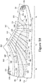
- knitted component 830 may have an oblong offset configuration that is outlined by a top forefoot perimeter edge 1300, a top side perimeter edge 1302, a pair of heel edges, including a medial heel edge 1304 and a lateral heel edge 1314, a bottom side perimeter edge 1312, and a bottom forefoot perimeter edge 1310.
- knit element 831 has a first side forming a portion of exterior surface 821 of upper 820 and an opposite second side that may form a portion of interior surface 822 of upper 820, thereby defining at least a portion of the void within upper 820.
- inlaid tensile element 832 may extend through portions of knit element 831, including portions of monofilament areas 860, between the first side and the second side of knit element 831.
- inlaid tensile element 832 repeatedly extends from top side perimeter edge 1302 toward instep area 850, where a portion of inlaid tensile element 832 forms a loop to serve as lace aperture 853, and back to top side perimeter edge 1302.
- Inlaid tensile element 832 may follow a similar path on the opposite side of knitted component 830.
- inlaid tensile element 832 repeatedly extends from bottom side perimeter edge 1312 toward instep area 850, where a portion of inlaid tensile element 832 forms a loop to serve as lace aperture 853, and back to bottom side perimeter edge 1312.
- portions of inlaid tensile element 832 may angle rearwards and extend to medial heel edge 1304 and/or lateral heel edge 1314. Additionally, inlaid tensile element 832 may pass through one or more monofilament areas 860 of knitted component 830, including portions of medial monofilament portion 862 and/or lateral monofilament portion 866, as inlaid tensile element 832 extends towards or away from top side perimeter edge 1302 and/or bottom side perimeter edge 1312.
- inlaid tensile element 832 may also pass through portions of forefoot monofilament portion 864 and/or heel monofilament portion 868 as inlaid tensile element 832 extends towards or away from medial heel edge 1304 and/or lateral heel edge 1314.
- inlaid tensile element 832 may exhibit greater stretch-resistance. That is, inlaid tensile element 832 may stretch less than knit element 831. Given that numerous sections of inlaid tensile element 832 extend through knit element 831, inlaid tensile element 832 may impart stretch-resistance to portions of upper 820 between instep area 850 and a lower area adjacent to sole structure 110. Moreover, placing tension upon lace 154 may impart tension to inlaid tensile element 832, thereby inducing the portions of upper 820 between instep area 850 and the lower area to lay against the foot.
- inlaid tensile element 832 may impart stretch-resistance to portions of upper 820 in heel region 14. Moreover, placing tension upon lace 154 may induce the portions of upper 820 in heel region 14 to lay against the foot. For example, inlaid tensile element 832 may assist with locating monofilament areas 860 along lateral side 16 and medial side 18 of upper 820 to lay flat against a foot of a wearer. As such, inlaid tensile element 832 operates in connection with lace 154 to enhance the fit of article 800.
- Knit element 831 may incorporate any of the various types of yarn discussed above for knitted component 130.
- the configuration of inlaid tensile element 832 may vary significantly.
- inlaid tensile element 832 may have the configurations of a filament (e.g., a monofilament), thread, rope, webbing, cable, or chain, for example.
- the thickness of inlaid tensile element 832 may be greater.
- inlaid tensile element 832 may have a significantly greater thickness than the yarns of knit element 831.
- inlaid tensile element 832 may be round, triangular, square, rectangular, elliptical, or irregular shapes may also be utilized.
- the materials forming inlaid tensile element 832 may include any of the materials for the yarn within knit element 831, such as cotton, elastane, polyester, rayon, wool, and nylon. As noted above, inlaid tensile element 832 may exhibit greater stretch-resistance than knit element 831.
- suitable materials for inlaid tensile element 832 may include a variety of engineering filaments that are utilized for high tensile strength applications, including glass, aramids (e.g., para-aramid and meta-aramid), ultra-high molecular weight polyethylene, and liquid crystal polymer.
- aramids e.g., para-aramid and meta-aramid
- ultra-high molecular weight polyethylene e.g
- one or more of the perimeter edges of knitted component 830 may be joined to form upper 820.
- knitted component 830 may be folded at a folding point 1306 between top forefoot perimeter edge 1300 and bottom forefoot perimeter edge 1310 to place top forefoot perimeter edge 1300 and bottom forefoot perimeter edge 1310 in contact with each other.
- top side perimeter edge 1302 may be placed in contact with bottom side perimeter edge 1312 and pair of heel edges, medial heel edge 1304 and lateral heel edge 1314, may be placed in contact with each other.
- medial heel edge 1304 and lateral heel edge 1314 may be joined along seam 829 disposed along medial side 18 of upper 820 in heel region 14.
- seam 829 may further extend along and connect each of top forefoot perimeter edge 1300 and bottom forefoot perimeter edge 1310 and top side perimeter edge 1302 and bottom side perimeter edge 1312 to form upper 820.
- monofilament areas 860 of knitted component 830 may include multiple types of monofilament areas 860 having different structures.
- monofilament areas 860 may include a first type of monofilament area formed from two knit layers knit with monofilament strands and a second type of monofilament area formed from two knit layers knit with a monofilament strand and natural or synthetic twisted fiber yarns.
- medial monofilament portion 862 and/or lateral monofilament portion 866 may be monofilament areas of the first type. That is, medial monofilament portion 862 and/or lateral monofilament portion 866 may include a first knit layer formed of a first monofilament strand 1400 and a second knit layer formed of a second monofilament strand 1401.
- monofilament areas 860 of this first type include knit layers formed of monofilament strands on both exterior surface 821 and interior surface 822 of upper 820.
- forefoot monofilament portion 864 and/or heel monofilament portion 868 may be monofilament areas of the second type. That is, forefoot monofilament portion 864 and/or heel monofilament portion 868 may include a first knit layer formed of monofilament strand 1400 and a second knit layer formed of a natural or synthetic twisted fiber yarn 1403.
- first knit layer formed of monofilament strand 1400 may be associated with exterior surface 821 of knitted component 830 and the second knit layer formed of natural or synthetic twisted fiber yarn 1403 may be associated with interior surface 822.
- inlaid tensile element 832 may be located between exterior surface 821 and interior surface 822 of upper 820. As shown in Figure 15C , inlaid tensile element 832 extends through heel monofilament portion 868 between the first knit layer formed of monofilament strand associated with exterior surface 821 and the second knit layer formed of natural or synthetic twisted fiber yarn associated with interior surface 822. In some configurations, portions of inlaid tensile element 832 may be visible through one or both of surfaces. In other embodiment, portions of inlaid tensile element 832 may lay against one of exterior surface 821 and/or interior surface 822, or knit element 831 may form indentations or apertures through which inlaid tensile element 832 passes.
- knit element 831 may have a similar two knit layer structure.
- a portion of knit element 831 may include a first knit layer formed of a first natural or synthetic twisted fiber yarn 1402 and a second knit layer formed of a second natural or synthetic twisted fiber yarn 1403.
- the first knit layer formed of first natural or synthetic twisted fiber yarn 1402 may be associated with exterior surface 821 of knitted component 830 and the second knit layer formed of second natural or synthetic twisted fiber yarn 1403 may be associated with interior surface 822.
- the same second natural or synthetic twisted fiber yarn 1403 may be used to knit monofilament areas 860 of the second type and the remaining portions of knitted component 830 that also include second natural or synthetic twisted fiber yarn 1403.
- monofilament areas 860 may be surrounded or circumscribed by the remaining portions of knitted component 830 so as to place monofilament areas 860 under tension, as described above with reference to knitted component 130.
- the tensioning force applied on monofilament areas 860 by the surrounding portion of knitted component 830 may assist with preventing or reducing kinks or sharp bends in monofilament strands in monofilament areas 860 that may produce an uncomfortable feeling to a foot of a wearer.
- knitted component 830 that includes medial monofilament portion 862 is illustrated.
- inlaid tensile element 832 extends through knit element 831 and medial monofilament portion 862.
- the portion of knitted component 830 at bottom medial boundary 906 may transition from monofilament strand 1400 forming medial monofilament portion 862 to natural or synthetic twisted fiber yarn 1402 forming the remaining portion of knit element 831, as described above.
- a first course 1600 of knitted component 830 and a fourth course 1606 of knitted component 830 transition from monofilament strand 1400 forming medial monofilament portion 862 to natural or synthetic twisted fiber yarn 1402 at bottom medial boundary 906.
- a second course 1602 and a third course 1604 of knitted component 830 also include inlaid tensile element 832.
- second course 1602 and third course 1604 also transition from monofilament strand 1400 to natural or synthetic twisted fiber yarn 1402, or another different type of yarn, at bottom medial boundary 906, as with first course 1600 and fourth course 1606.
- second course 1602 and third course 1604 may correspond with inlaid tensile element 832 as inlaid tensile element 832 extends through knit element 831.
- inlaid tensile element 832 may extend through monofilament strand 1400 in medial monofilament portion 862, and continue extending through natural or synthetic twisted fiber yarn 1402 in the remaining portion of knit element 831.
- natural or synthetic twisted fiber yarn 1402 may substantially surround portions of inlaid tensile element 832 as it extends through the remaining portions of knit element 831 outside of medial monofilament portion 862.
- inlaid tensile element 832 may be hidden from view on exterior surface 821 of knitted component 830 outside of monofilament areas 860.
- one or more courses of knitted component 830 that include a monofilament strand may extend along through the remaining portions of knit element 831 beyond monofilament areas 860.
- Figure 16B an optional configuration for a portion of knitted component 830 that includes medial monofilament portion 862 is illustrated.
- inlaid tensile element 832 extends through knit element 831 and medial monofilament portion 862.
- one or more courses formed by a monofilament strand for example monofilament strand 1400, described above, may further extend through knit element 831 outside of medial monofilament portion 862 together with inlaid tensile element 832.
- the portion of knitted component 830 at bottom medial boundary 906 may transition from monofilament strand 1400 forming medial monofilament portion 862 to natural or synthetic twisted fiber yarn 1402 forming the remaining portion of knit element 831, as described above.
- a first course 1600 of knitted component 830 and a fourth course 1606 of knitted component 830 transition from monofilament strand 1400 forming medial monofilament portion 862 to natural or synthetic twisted fiber yarn 1402 at bottom medial boundary 906.
- a second course 1602 and a third course 1604 of knitted component 830 do not transition from monofilament strand 1400 to natural or synthetic twisted fiber yarn 1402 , or another different type of yarn, at bottom medial boundary 906. Instead, second course 1602 and third course 1604 continue in a substantially continuous manner to be formed with the same monofilament strand 1400 forming medial monofilament portion 862.
- second course 1602 and third course 1604 knit with monofilament strand 1400 may correspond with inlaid tensile element 832 as inlaid tensile element 832 extends through knit element 831.
- inlaid tensile element 832 may extend through monofilament strand 1400 in medial monofilament portion 862, as well as through the remaining portion of knit element 831.
- monofilament strand 1400 may substantially surround portions of inlaid tensile element 832 as it extends through the remaining portions of knit element 831 outside of medial monofilament portion 862.
- one or more courses of monofilament strands may extend outside of each monofilament areas 860, including medial monofilament portion 862, forefoot monofilament portion 864, lateral monofilament portion 866, and/or heel monofilament portion 868, to follow and correspond with the path of inlaid tensile element 832 throughout knitted component 830.
- medial monofilament portion 862 forefoot monofilament portion 864, lateral monofilament portion 866, and/or heel monofilament portion 868
- additional strength and support may be provided to inlaid tensile element 832.
- monofilament areas 860 of the second type i.e., two knit layers having one knit layer formed of a monofilament strand and one knit layer formed of natural or synthetic twisted fiber yarns, may be knit with a knit structure that forms plurality of indentations during the knitting process in the knit layer formed of natural or synthetic twisted fiber yarns.
- Such a configuration may further provide ventilation to the interior of upper 820 while still providing a comfortable feel to a foot of a wearer along interior surface 822.
- a suitable knit structure for forming monofilament areas 860 of the second type includes a 1x1 inverted mock mesh knit structure or 2x2 inverted mock mesh structure.
- a mesh knit structure which may be used to form apertures that extend fully through a knit element, including both a first knit layer and a second knit layer
- an inverted mock mesh knit structure forms indentations in second knit layer, i.e., the layer associated with interior surface 822 of upper 820.
- An exemplary embodiment of a looping diagram 1700 for knitting an inverted 2x2 mock mesh structure is illustrated.
- looping diagram 1700 illustrates the sequence of stitches and movements performed by a knitting machine, for example, a flat-knitting machine, to form an inverted 2x2 mock mesh structure making up a portion of monofilament areas 860 of the second type.
- a knitting machine for example, a flat-knitting machine
- the spaced apart dots represent the needles of a knitting machine and the illustrated steps represent the direction of movement of a yarn or strand between the needles of each of a front bed and a back bed of a knitting machine.
- monofilament strand 1400 may be used to knit the first knit layer of monofilament area 860 that is associated with exterior surface 821 of upper 820, while natural or synthetic twisted fiber yarn 1403 may be used to knit the second knit layer of monofilament area 860 that is associated with interior surface 822 of upper 820.
- the second knit layer includes a number of tuck stitches performed with or natural or synthetic twisted fiber yarn 1403.
- the width or gap in second knit layer is associated with 2 needles to form the inverted 2x2 mock mesh structure.
- such an inverted 2x2 mock mesh structure may be used to form one or more of forefoot monofilament portion 864 and/or heel monofilament portion 868, described above.
- a larger or smaller knit structure may be provided by making the gap associated with a larger or smaller number of needles.
- an inverted 3x3 mock mesh structure may be formed by increasing the gap to 3 needles and an inverted 1 x1 mock mesh structure may be formed by decreasing the gap to a single needle.
- Figure 17 illustrates one exemplary embodiment of a knit structure that may be used with knitted component 830 to form a portion of monofilament areas 860.
- Mesh knit structures, mock mesh knit structures, and other suitable knit structures with accompanying loop diagrams for knitting such knit structures for use in the present embodiments are described in U.S. Patent Application Publication 2012/0233882 to Huffa et al. , which was referenced above and incorporated herein.
Applications Claiming Priority (3)
| Application Number | Priority Date | Filing Date | Title |
|---|---|---|---|
| US14/026,531 US20150075031A1 (en) | 2013-09-13 | 2013-09-13 | Article Of Footwear Incorporating A Knitted Component With Monofilament Areas |
| EP14771994.2A EP3043671B1 (en) | 2013-09-13 | 2014-08-28 | Article of footwear incorporating a knitted component with monofilament areas |
| PCT/US2014/053090 WO2015038344A1 (en) | 2013-09-13 | 2014-08-28 | Article of footwear incorporating a knitted component with monofilament areas |
Related Parent Applications (2)
| Application Number | Title | Priority Date | Filing Date |
|---|---|---|---|
| EP14771994.2A Division EP3043671B1 (en) | 2013-09-13 | 2014-08-28 | Article of footwear incorporating a knitted component with monofilament areas |
| EP14771994.2A Division-Into EP3043671B1 (en) | 2013-09-13 | 2014-08-28 | Article of footwear incorporating a knitted component with monofilament areas |
Publications (1)
| Publication Number | Publication Date |
|---|---|
| EP3482649A1 true EP3482649A1 (en) | 2019-05-15 |
Family
ID=51589507
Family Applications (2)
| Application Number | Title | Priority Date | Filing Date |
|---|---|---|---|
| EP18203452.0A Pending EP3482649A1 (en) | 2013-09-13 | 2014-08-28 | Article of footwear incorporating a knitted component with monofilament areas |
| EP14771994.2A Active EP3043671B1 (en) | 2013-09-13 | 2014-08-28 | Article of footwear incorporating a knitted component with monofilament areas |
Family Applications After (1)
| Application Number | Title | Priority Date | Filing Date |
|---|---|---|---|
| EP14771994.2A Active EP3043671B1 (en) | 2013-09-13 | 2014-08-28 | Article of footwear incorporating a knitted component with monofilament areas |
Country Status (10)
| Country | Link |
|---|---|
| US (1) | US20150075031A1 (zh) |
| EP (2) | EP3482649A1 (zh) |
| JP (1) | JP6406720B2 (zh) |
| KR (1) | KR101993964B1 (zh) |
| CN (4) | CN105578917A (zh) |
| AR (1) | AR097640A1 (zh) |
| HK (2) | HK1207944A1 (zh) |
| MX (1) | MX364868B (zh) |
| TW (2) | TWM498500U (zh) |
| WO (1) | WO2015038344A1 (zh) |
Families Citing this family (64)
| Publication number | Priority date | Publication date | Assignee | Title |
|---|---|---|---|---|
| US7774956B2 (en) | 2006-11-10 | 2010-08-17 | Nike, Inc. | Article of footwear having a flat knit upper construction or other upper construction |
| CN104066350B (zh) * | 2012-01-20 | 2016-04-27 | 株式会社岛精机制作所 | 鞋袜及编织物的编织方法 |
| US10182617B2 (en) | 2012-11-20 | 2019-01-22 | Nike, Inc. | Footwear upper incorporating a knitted component with collar and throat portions |
| US9936757B2 (en) * | 2013-03-04 | 2018-04-10 | Nike, Inc. | Article of footwear incorporating a knitted component with integrally knit contoured portion |
| DE102013207156A1 (de) | 2013-04-19 | 2014-10-23 | Adidas Ag | Schuh, insbesondere ein Sportschuh |
| DE102013207163B4 (de) | 2013-04-19 | 2022-09-22 | Adidas Ag | Schuhoberteil |
| US11666113B2 (en) | 2013-04-19 | 2023-06-06 | Adidas Ag | Shoe with knitted outer sole |
| DE102013207155B4 (de) | 2013-04-19 | 2020-04-23 | Adidas Ag | Schuhoberteil |
| US20140373389A1 (en) * | 2013-06-25 | 2014-12-25 | Nike, Inc. | Braided Upper With Overlays For Article Of Footwear |
| US10863794B2 (en) | 2013-06-25 | 2020-12-15 | Nike, Inc. | Article of footwear having multiple braided structures |
| CA3020031A1 (en) | 2013-06-25 | 2014-12-31 | Nike Innovate C.V. | Article of footwear with braided upper |
| US20150075031A1 (en) * | 2013-09-13 | 2015-03-19 | Nike, Inc. | Article Of Footwear Incorporating A Knitted Component With Monofilament Areas |
| US8997529B1 (en) * | 2014-02-03 | 2015-04-07 | Nike, Inc. | Article of footwear including a monofilament knit element with peripheral knit portions |
| US8973410B1 (en) | 2014-02-03 | 2015-03-10 | Nike, Inc. | Method of knitting a gusseted tongue for a knitted component |
| DE102014202432B4 (de) | 2014-02-11 | 2017-07-27 | Adidas Ag | Verbesserter Fußballschuh |
| US10383388B2 (en) | 2014-03-07 | 2019-08-20 | Nike, Inc. | Article of footware with upper incorporating knitted component providing variable compression |
| US9877536B2 (en) | 2014-05-30 | 2018-01-30 | Nike, Inc. | Method of making an article of footwear including knitting a knitted component of warp knit construction forming a seamless bootie with wrap-around portion |
| JP6276906B2 (ja) * | 2014-07-25 | 2018-02-07 | 美津濃株式会社 | スポーツシューズのアッパー構造およびその製造方法 |
| US20160058099A1 (en) * | 2014-08-29 | 2016-03-03 | Nike, Inc. | Article of Footwear Incorporating a Knitted Component with Monofilament Areas in Body and Heel Portions |
| DE102014220087B4 (de) | 2014-10-02 | 2016-05-12 | Adidas Ag | Flachgestricktes Schuhoberteil für Sportschuhe |
| US10674791B2 (en) | 2014-12-10 | 2020-06-09 | Nike, Inc. | Braided article with internal midsole structure |
| US9668544B2 (en) | 2014-12-10 | 2017-06-06 | Nike, Inc. | Last system for articles with braided components |
| US10294591B2 (en) | 2015-01-30 | 2019-05-21 | Nike, Inc. | Method for forming a seamless knitted abutment |
| US10130142B2 (en) * | 2015-04-14 | 2018-11-20 | Nike, Inc. | Article of footwear with knitted component having biased inter-toe member |
| EP4272593A3 (en) | 2015-04-16 | 2024-01-17 | NIKE Innovate C.V. | Article of footwear incorporating a knitted component having floated portions |
| US10555581B2 (en) | 2015-05-26 | 2020-02-11 | Nike, Inc. | Braided upper with multiple materials |
| US20160345675A1 (en) | 2015-05-26 | 2016-12-01 | Nike, Inc. | Hybrid Braided Article |
| TW201708649A (zh) * | 2015-05-29 | 2017-03-01 | 島精機製作所股份有限公司 | 鞋面與其編織方法 |
| TWI723627B (zh) * | 2015-05-29 | 2021-04-01 | 荷蘭商耐克創新有限合夥公司 | 鞋類物件以及用集成領襯製造鞋類物件的方法 |
| US11103028B2 (en) | 2015-08-07 | 2021-08-31 | Nike, Inc. | Multi-layered braided article and method of making |
| US9961962B2 (en) * | 2015-08-18 | 2018-05-08 | Action Sports Equipment Inc. | Article of footwear having active regions and secure regions |
| US10524530B2 (en) * | 2016-02-16 | 2020-01-07 | Nike, Inc. | Upper for an article of footwear with at least one molded thermoplastic polymer element |
| EP4026936A1 (en) * | 2016-04-01 | 2022-07-13 | NIKE Innovate C.V. | Shoe upper having a knitted component with a strap |
| DE102016207387B4 (de) * | 2016-04-29 | 2021-11-18 | Adidas Ag | Socke |
| ITUA20164535A1 (it) * | 2016-06-01 | 2017-12-01 | Pro Eight S R L | Tomaia per calzature. |
| US10327511B2 (en) | 2016-07-08 | 2019-06-25 | Cole Haan Llc | Shoe having knit wingtip upper |
| US11445779B2 (en) * | 2016-07-21 | 2022-09-20 | Nike, Inc. | Article of footwear with multiple layers, retention system for an article of footwear, and methods of manufacture |
| US11166516B2 (en) * | 2016-08-26 | 2021-11-09 | Nike, Inc. | Article of footwear having an upper that includes a knitted component with a cushioning region and methods for fabricating the same |
| US10842228B2 (en) * | 2016-11-22 | 2020-11-24 | Wholeknit International Co., Ltd. | Method for manufacturing shoe embryo tailored from tubular fabric and associated shoe embryo |
| EP3547867B1 (en) | 2016-12-02 | 2021-07-21 | Nike Innovate C.V. | Footwear with aligned tensile restraints |
| US20190387839A1 (en) * | 2017-02-03 | 2019-12-26 | Nike, Inc. | Fiber-Bound Engineered Materials Formed Using Zonal Scrims |
| US10194714B2 (en) * | 2017-03-07 | 2019-02-05 | Adidas Ag | Article of footwear with upper having stitched polymer thread pattern and methods of making the same |
| US10694817B2 (en) * | 2017-03-07 | 2020-06-30 | Adidas Ag | Article of footwear with upper having stitched polymer thread pattern and methods of making the same |
| CN110730835B (zh) | 2017-05-05 | 2022-03-04 | 耐克创新有限合伙公司 | 具有第一针织部分和第二针织部分的用于鞋类物品的鞋面以及制造鞋面的方法 |
| US11202483B2 (en) | 2017-05-31 | 2021-12-21 | Nike, Inc. | Braided articles and methods for their manufacture |
| US11051573B2 (en) | 2017-05-31 | 2021-07-06 | Nike, Inc. | Braided articles and methods for their manufacture |
| US10806210B2 (en) | 2017-05-31 | 2020-10-20 | Nike, Inc. | Braided articles and methods for their manufacture |
| WO2019028350A1 (en) * | 2017-08-04 | 2019-02-07 | Nike Innovate C.V. | FOOTWEAR WITH A KNITTED ELEMENT HAVING A FOREWORD PART AND A HEEL PART |
| WO2019046387A2 (en) * | 2017-08-31 | 2019-03-07 | Nike Innovate C.V. | FOOTWEAR WITH A SOFT ROD AND STRUCTURE HAVING SUBSTANTIALLY EQUAL FRICTION COEFFICIENTS |
| US10791791B2 (en) * | 2018-01-20 | 2020-10-06 | Nike, Inc. | Articles of footwear reinforced with high tenacity yarn |
| US11365494B2 (en) | 2018-08-09 | 2022-06-21 | Nike, Inc. | Knitted component with a fused surface region located on a tubular knit structure |
| USD913647S1 (en) | 2018-08-29 | 2021-03-23 | Puma SE | Shoe |
| USD891739S1 (en) | 2018-08-29 | 2020-08-04 | Puma SE | Shoe |
| USD885719S1 (en) | 2018-08-29 | 2020-06-02 | Puma SE | Shoe |
| USD880825S1 (en) | 2018-08-29 | 2020-04-14 | Puma SE | Shoe |
| US11925234B2 (en) * | 2018-09-28 | 2024-03-12 | Puma SE | Article of footwear having an upper assembly |
| US11013292B2 (en) | 2018-09-28 | 2021-05-25 | Puma SE | Article of footwear having a sole structure |
| US20200170330A1 (en) * | 2018-12-03 | 2020-06-04 | Cole Haan Llc | Shoe with Knit Upper |
| GB2589378A (en) * | 2019-11-29 | 2021-06-02 | Texon Man Limited | A woven upper |
| US11439206B2 (en) * | 2019-12-17 | 2022-09-13 | Under Armour, Inc. | Method of making an article of footwear with braided upper |
| CA3162828A1 (en) * | 2019-12-26 | 2021-07-01 | Lululemon Athletica Canada Inc. | Footwear upper comprising stretch zones |
| WO2023135814A1 (ja) * | 2022-01-17 | 2023-07-20 | 株式会社アシックス | アッパー、シューズ及びアッパーの製造方法 |
| WO2023135813A1 (ja) * | 2022-01-17 | 2023-07-20 | 株式会社アシックス | アッパー、シューズ及びアッパーの製造方法 |
| US20240081465A1 (en) * | 2022-09-14 | 2024-03-14 | Lululemon Athletica Canada Inc. | Upper for Article of Footwear Incorporating a Knitted Butterfly Workpiece |
Citations (4)
| Publication number | Priority date | Publication date | Assignee | Title |
|---|---|---|---|---|
| US4785558A (en) * | 1986-07-31 | 1988-11-22 | Toray Industries, Inc. | Shoe upper of interknitted outer and inner knit layers |
| US20040118018A1 (en) * | 2002-12-18 | 2004-06-24 | Bhupesh Dua | Footwear incorporating a textile with fusible filaments and fibers |
| US20080110048A1 (en) * | 2006-11-10 | 2008-05-15 | Nike, Inc. | Article of footwear having a flat knit upper construction or other upper construction |
| US20120233882A1 (en) | 2011-03-15 | 2012-09-20 | NIKE. Inc. | Article Of Footwear Incorporating A Knitted Component |
Family Cites Families (17)
| Publication number | Priority date | Publication date | Assignee | Title |
|---|---|---|---|---|
| US5385036A (en) * | 1993-05-24 | 1995-01-31 | Guilford Mills, Inc. | Warp knitted textile spacer fabric, method of producing same, and products produced therefrom |
| BR9602748A (pt) * | 1995-06-13 | 1998-04-22 | Faytex Corp | Estrutura para calçado |
| US6931762B1 (en) * | 2002-12-18 | 2005-08-23 | Nike, Inc. | Footwear with knit upper and method of manufacturing the footwear |
| US7424783B2 (en) * | 2003-06-30 | 2008-09-16 | Nike, Inc. | Article of apparel incorporating a stratified material |
| US7347011B2 (en) * | 2004-03-03 | 2008-03-25 | Nike, Inc. | Article of footwear having a textile upper |
| US8312646B2 (en) * | 2006-05-25 | 2012-11-20 | Nike, Inc. | Article of footwear incorporating a tensile element |
| US8418380B2 (en) * | 2006-05-25 | 2013-04-16 | Nike, Inc. | Article of footwear having an upper incorporating a tensile strand with a cover layer |
| MX2010002835A (es) * | 2007-09-12 | 2010-04-30 | Maidenform Inc | Tela que tiene un hebra fundible termoplastica procedimiento para elaborar una tela que contiene hebra fundible termoplastica, y articulo de tela que se forma con una tela que contiene una hebra fundible termoplastica. |
| US8490299B2 (en) * | 2008-12-18 | 2013-07-23 | Nike, Inc. | Article of footwear having an upper incorporating a knitted component |
| US20100199406A1 (en) * | 2009-02-06 | 2010-08-12 | Nike, Inc. | Thermoplastic Non-Woven Textile Elements |
| WO2011009112A2 (en) * | 2009-07-17 | 2011-01-20 | Federal-Mogul Powertrain,Inc | Tri-layer knit fabric, thermal protective members formed therefrom and methods of construction thereof. |
| US8800172B2 (en) * | 2011-04-04 | 2014-08-12 | Nike, Inc. | Article of footwear having a knit upper with a polymer layer |
| US9076431B2 (en) * | 2011-06-03 | 2015-07-07 | Cirrus Logic, Inc. | Filter architecture for an adaptive noise canceler in a personal audio device |
| US8448474B1 (en) * | 2012-02-20 | 2013-05-28 | Nike, Inc. | Article of footwear incorporating a knitted component with a tongue |
| DE102012206062B4 (de) * | 2012-04-13 | 2019-09-12 | Adidas Ag | Schuhoberteil |
| DE102013207155B4 (de) * | 2013-04-19 | 2020-04-23 | Adidas Ag | Schuhoberteil |
| US20150075031A1 (en) * | 2013-09-13 | 2015-03-19 | Nike, Inc. | Article Of Footwear Incorporating A Knitted Component With Monofilament Areas |
-
2013
- 2013-09-13 US US14/026,531 patent/US20150075031A1/en not_active Abandoned
-
2014
- 2014-08-28 KR KR1020167009717A patent/KR101993964B1/ko active IP Right Grant
- 2014-08-28 CN CN201480050535.8A patent/CN105578917A/zh active Pending
- 2014-08-28 EP EP18203452.0A patent/EP3482649A1/en active Pending
- 2014-08-28 CN CN201910428511.6A patent/CN110051073B/zh active Active
- 2014-08-28 EP EP14771994.2A patent/EP3043671B1/en active Active
- 2014-08-28 MX MX2016003243A patent/MX364868B/es active IP Right Grant
- 2014-08-28 JP JP2016541998A patent/JP6406720B2/ja active Active
- 2014-08-28 WO PCT/US2014/053090 patent/WO2015038344A1/en active Application Filing
- 2014-09-11 AR ARP140103402A patent/AR097640A1/es active IP Right Grant
- 2014-09-11 CN CN201410461366.9A patent/CN104432931B/zh active Active
- 2014-09-11 CN CN201420521102.3U patent/CN204351151U/zh not_active Withdrawn - After Issue
- 2014-09-12 TW TW103216283U patent/TWM498500U/zh unknown
- 2014-09-12 TW TW103131646A patent/TWI602520B/zh active
-
2015
- 2015-09-04 HK HK15108615.1A patent/HK1207944A1/zh unknown
-
2016
- 2016-10-18 HK HK16112001.4A patent/HK1223522A1/zh unknown
Patent Citations (5)
| Publication number | Priority date | Publication date | Assignee | Title |
|---|---|---|---|---|
| US4785558A (en) * | 1986-07-31 | 1988-11-22 | Toray Industries, Inc. | Shoe upper of interknitted outer and inner knit layers |
| US4785558B1 (en) * | 1986-07-31 | 1998-04-21 | Toray Industries | Shoe upper of interknitted outer and inner knit layers |
| US20040118018A1 (en) * | 2002-12-18 | 2004-06-24 | Bhupesh Dua | Footwear incorporating a textile with fusible filaments and fibers |
| US20080110048A1 (en) * | 2006-11-10 | 2008-05-15 | Nike, Inc. | Article of footwear having a flat knit upper construction or other upper construction |
| US20120233882A1 (en) | 2011-03-15 | 2012-09-20 | NIKE. Inc. | Article Of Footwear Incorporating A Knitted Component |
Also Published As
| Publication number | Publication date |
|---|---|
| CN110051073A (zh) | 2019-07-26 |
| WO2015038344A8 (en) | 2015-11-12 |
| AR097640A1 (es) | 2016-04-06 |
| EP3043671B1 (en) | 2019-01-16 |
| WO2015038344A1 (en) | 2015-03-19 |
| HK1223522A1 (zh) | 2017-08-04 |
| CN105578917A (zh) | 2016-05-11 |
| CN204351151U (zh) | 2015-05-27 |
| TWM498500U (zh) | 2015-04-11 |
| KR20160058846A (ko) | 2016-05-25 |
| MX364868B (es) | 2019-05-09 |
| KR101993964B1 (ko) | 2019-06-27 |
| TWI602520B (zh) | 2017-10-21 |
| HK1207944A1 (zh) | 2016-02-19 |
| CN104432931B (zh) | 2017-04-12 |
| EP3043671A1 (en) | 2016-07-20 |
| MX2016003243A (es) | 2016-06-07 |
| US20150075031A1 (en) | 2015-03-19 |
| JP2016530041A (ja) | 2016-09-29 |
| TW201513803A (zh) | 2015-04-16 |
| CN110051073B (zh) | 2022-05-06 |
| CN104432931A (zh) | 2015-03-25 |
| JP6406720B2 (ja) | 2018-10-17 |
Similar Documents
| Publication | Publication Date | Title |
|---|---|---|
| EP3043671B1 (en) | Article of footwear incorporating a knitted component with monofilament areas | |
| US9777412B2 (en) | Article of footwear including a monofilament knit element with a fusible strand | |
| US9745678B2 (en) | Article of footwear including a monofilament knit element with peripheral knit portions | |
| US9803299B2 (en) | Knitted component for an article of footwear including a full monofilament upper | |
| US9668533B2 (en) | Article of footwear having an upper incorporating a knitted component | |
| US8973410B1 (en) | Method of knitting a gusseted tongue for a knitted component | |
| US7774956B2 (en) | Article of footwear having a flat knit upper construction or other upper construction | |
| US20080110049A1 (en) | Article of footwear having a flat knit upper construction or other upper construction |
Legal Events
| Date | Code | Title | Description |
|---|---|---|---|
| PUAI | Public reference made under article 153(3) epc to a published international application that has entered the european phase |
Free format text: ORIGINAL CODE: 0009012 |
|
| STAA | Information on the status of an ep patent application or granted ep patent |
Free format text: STATUS: REQUEST FOR EXAMINATION WAS MADE |
|
| 17P | Request for examination filed |
Effective date: 20181030 |
|
| AC | Divisional application: reference to earlier application |
Ref document number: 3043671 Country of ref document: EP Kind code of ref document: P |
|
| AK | Designated contracting states |
Kind code of ref document: A1 Designated state(s): AL AT BE BG CH CY CZ DE DK EE ES FI FR GB GR HR HU IE IS IT LI LT LU LV MC MK MT NL NO PL PT RO RS SE SI SK SM TR |
|
| STAA | Information on the status of an ep patent application or granted ep patent |
Free format text: STATUS: EXAMINATION IS IN PROGRESS |
|
| 17Q | First examination report despatched |
Effective date: 20230116 |
|
| P01 | Opt-out of the competence of the unified patent court (upc) registered |
Effective date: 20230515 |