EP3480999B1 - Customizable encryption/decryption algorithm - Google Patents
Customizable encryption/decryption algorithm Download PDFInfo
- Publication number
- EP3480999B1 EP3480999B1 EP18204262.2A EP18204262A EP3480999B1 EP 3480999 B1 EP3480999 B1 EP 3480999B1 EP 18204262 A EP18204262 A EP 18204262A EP 3480999 B1 EP3480999 B1 EP 3480999B1
- Authority
- EP
- European Patent Office
- Prior art keywords
- bit
- bits
- permutation
- input
- layer
- Prior art date
- Legal status (The legal status is an assumption and is not a legal conclusion. Google has not performed a legal analysis and makes no representation as to the accuracy of the status listed.)
- Active
Links
Images



Classifications
-
- H—ELECTRICITY
- H04—ELECTRIC COMMUNICATION TECHNIQUE
- H04L—TRANSMISSION OF DIGITAL INFORMATION, e.g. TELEGRAPHIC COMMUNICATION
- H04L9/00—Cryptographic mechanisms or cryptographic arrangements for secret or secure communications; Network security protocols
- H04L9/14—Cryptographic mechanisms or cryptographic arrangements for secret or secure communications; Network security protocols using a plurality of keys or algorithms
-
- G—PHYSICS
- G09—EDUCATION; CRYPTOGRAPHY; DISPLAY; ADVERTISING; SEALS
- G09C—CIPHERING OR DECIPHERING APPARATUS FOR CRYPTOGRAPHIC OR OTHER PURPOSES INVOLVING THE NEED FOR SECRECY
- G09C1/00—Apparatus or methods whereby a given sequence of signs, e.g. an intelligible text, is transformed into an unintelligible sequence of signs by transposing the signs or groups of signs or by replacing them by others according to a predetermined system
-
- H—ELECTRICITY
- H04—ELECTRIC COMMUNICATION TECHNIQUE
- H04L—TRANSMISSION OF DIGITAL INFORMATION, e.g. TELEGRAPHIC COMMUNICATION
- H04L9/00—Cryptographic mechanisms or cryptographic arrangements for secret or secure communications; Network security protocols
- H04L9/001—Cryptographic mechanisms or cryptographic arrangements for secret or secure communications; Network security protocols using chaotic signals
-
- H—ELECTRICITY
- H04—ELECTRIC COMMUNICATION TECHNIQUE
- H04L—TRANSMISSION OF DIGITAL INFORMATION, e.g. TELEGRAPHIC COMMUNICATION
- H04L9/00—Cryptographic mechanisms or cryptographic arrangements for secret or secure communications; Network security protocols
- H04L9/06—Cryptographic mechanisms or cryptographic arrangements for secret or secure communications; Network security protocols the encryption apparatus using shift registers or memories for block-wise or stream coding, e.g. DES systems or RC4; Hash functions; Pseudorandom sequence generators
-
- H—ELECTRICITY
- H04—ELECTRIC COMMUNICATION TECHNIQUE
- H04L—TRANSMISSION OF DIGITAL INFORMATION, e.g. TELEGRAPHIC COMMUNICATION
- H04L9/00—Cryptographic mechanisms or cryptographic arrangements for secret or secure communications; Network security protocols
- H04L9/06—Cryptographic mechanisms or cryptographic arrangements for secret or secure communications; Network security protocols the encryption apparatus using shift registers or memories for block-wise or stream coding, e.g. DES systems or RC4; Hash functions; Pseudorandom sequence generators
- H04L9/0618—Block ciphers, i.e. encrypting groups of characters of a plain text message using fixed encryption transformation
- H04L9/0631—Substitution permutation network [SPN], i.e. cipher composed of a number of stages or rounds each involving linear and nonlinear transformations, e.g. AES algorithms
-
- H—ELECTRICITY
- H04—ELECTRIC COMMUNICATION TECHNIQUE
- H04L—TRANSMISSION OF DIGITAL INFORMATION, e.g. TELEGRAPHIC COMMUNICATION
- H04L9/00—Cryptographic mechanisms or cryptographic arrangements for secret or secure communications; Network security protocols
- H04L9/06—Cryptographic mechanisms or cryptographic arrangements for secret or secure communications; Network security protocols the encryption apparatus using shift registers or memories for block-wise or stream coding, e.g. DES systems or RC4; Hash functions; Pseudorandom sequence generators
- H04L9/065—Encryption by serially and continuously modifying data stream elements, e.g. stream cipher systems, RC4, SEAL or A5/3
- H04L9/0656—Pseudorandom key sequence combined element-for-element with data sequence, e.g. one-time-pad [OTP] or Vernam's cipher
- H04L9/0662—Pseudorandom key sequence combined element-for-element with data sequence, e.g. one-time-pad [OTP] or Vernam's cipher with particular pseudorandom sequence generator
-
- H—ELECTRICITY
- H04—ELECTRIC COMMUNICATION TECHNIQUE
- H04L—TRANSMISSION OF DIGITAL INFORMATION, e.g. TELEGRAPHIC COMMUNICATION
- H04L9/00—Cryptographic mechanisms or cryptographic arrangements for secret or secure communications; Network security protocols
- H04L9/08—Key distribution or management, e.g. generation, sharing or updating, of cryptographic keys or passwords
- H04L9/0861—Generation of secret information including derivation or calculation of cryptographic keys or passwords
- H04L9/0869—Generation of secret information including derivation or calculation of cryptographic keys or passwords involving random numbers or seeds
Definitions
- This document relates generally to cryptographic systems. More particularly, this document relates to cryptographic systems implementing a customizable encryption algorithm.
- the cryptographic algorithm implements a method that generally involves: combining a cryptographic key with state initialization bits to generate first combination bits; producing a first keystream by performing a permutation function f using the first combination bits as inputs thereto; and using the first keystream to encrypt first data (e.g., authentication data or message body data) so as to produce first encrypted data (e.g., via modular arithmetic).
- the permutation function f comprises a round function fround that is iterated R times.
- the round function fround consists of (1) a substitution layer in which the first combination bits are substituted with substitute bits, (2) a permutation layer in which the substitute bits are re-arranged, (3) a mixing layer in which at least two outputs of the permutation layer are combined together, and (4) an addition layer in which a constant is added to the output of the mixing layer.
- Document US2007071236 discloses a method and system to encrypt and decrypt data.
- the method disclosed therein comprises providing input data to be encrypted, said input data made up of a plurality of sub-data, each said sub-data comprising sequence of bits of data; dynamically selecting a plurality of invertible encryption parameters; and performing one or more rounds of a combination of data modification, sequence modification and data-sequence modification using plurality of selected encryption parameters deriving encrypted data.
- the system includes a processor for executing code for dynamically selecting a plurality of invertible encryption parameters.
- Document US2012237020 discloses a key variable loader that receives a set of Rijndael parameters that were verified using a simulation computer, wherein the set of Rijndael parameters provide an input for implementing at least one step of the Rijndael block cipher and when used with a secret key allow a conversion between plain text and cipher text using the Rijndael block cipher.
- the key variable loader further stores the set of Rijndael parameters and subsequently provides the set of Rijndael parameters to a device having a customizable Rijndael block cipher, like a subscriber unit or a key management facility.
- Document US2012/237020A1 further discloses a SubBytes transform, which a non-linear substitution step where each byte is replaced with another according to an S-box (substitution box) that is in standard AES a lookup table configurable based upon the Rijndael parameters provided at the input.
- INDRAJIT DAS ET AL "Random S-Box generation in AES by changing irreducible polynomial",COMMUNICATIONS, DEVICES AND INTELLIGENT SYSTEMS (CODIS), 2012 INTERNATIONAL CONFERENCE ON, IEEE, 28 December 2012 (2012-12-28), pages 556-559 , discloses random S-Box Generation in AES by changing irreducible polynomial.
- KELLY MATTHEW ET AL "Customizable sponge-based authenticated encryption using 16-bit S-boxes", MILCOM 2015 - 2015 IEEE MILITARY COMMUNICATIONS CONFERENCE, IEEE, 26 October 2015 (2015-10-26), pages 43-48 , discloses a sponge function based on an SPN network that can be customized at several levels: initialization, S-Box, permutation, mixing layer and constant to be added.
- the present disclosure concerns implementing systems and methods for customizing a cryptographic algorithm (e.g., an encryption algorithm and/or a decryption algorithm).
- the customization of the cryptographic algorithm does not cause any degeneration of its security.
- the invention is defined by the independent claim.
- the methods comprise: providing an electronic device with the cryptographic algorithm implementing a permutation function f configured to produce a first keystream using bits input thereto, the permutation function f comprising a round function fround consisting of a mixing layer in which input bits are combined together; and customizing the mixing layer of the permutation function f while the electronic device is in the field.
- the mixing layer is customized by: receiving, by the electronic device, a first user-software interaction for entering a first bit string comprising a plurality of first arbitrary bits; breaking the first bit string into a plurality of equal length segments each comprising only a portion of the plurality of first bits; translating each of the equal length segments into irreducible polynomial coefficients; and causing a respective one of a plurality of mixers comprising the mixing layer to use the irreducible polynomial coefficients.
- the methods further comprise: receiving a second user-software interaction for selecting a set of irreducible polynomial equations from a plurality of polynomial equations; and programming the selected set of irreducible polynomial equations for possible use by the mixers of the mixing layer.
- Each of the plurality of polynomial equations may comprise a degree-16 irreducible polynomial equation.
- the round function f round further consists of a substitution layer in which input bits are substituted with substitute bits.
- the bit substitutions of the substitution layer are performed by a plurality of customizable S-boxes.
- At least one S-box of the plurality of customizable S-boxes is customized by changing a polynomial equation and/or by changing an input-to-output bit mapping, such that the S-box: (1) has input values and output values that are all different; (2) does not have an output value that is equal to the corresponding input value; (3) does not have an output value that is a bitwise complement of the corresponding input value; (4) has a maximum differential probability of 2 -14 or smaller; and (5) has a maximum linear bias of 2 -8 or smaller.
- the values may be randomly selected in accordance with a chaotic, random or pseudo-random number algorithm.
- the same or different chaotic, random or pseudo-random number algorithm is used to specify values for the multi-bit invertible matrix A and the multi-bit vector b .
- the present solution is not limited to the particulars of this example.
- the round function f round further consists of a customizable permutation layer in which bits are rearranged.
- the customizable permutation layer is customized by changing a permutation formula such that the following criteria is met: (1) each output bit of a given S-box goes to a different mixer's input bit; (2) bit positions of bits input to the permutation layer are different than the positions of corresponding bits output from the permutation layer; and (3) an order of each bit position is greater than a number of rounds in a bijective function.
- the round function f round further consists of a customizable addition layer in which a constant is added to an output of the mixing layer.
- the customizable addition layer is customized by selecting a plurality of round constant values such that (1) there are no identifiable patterns in the plurality of round constant values and (2) the round constant values are different for each round.
- Each round constant value of the plurality of round constant values can have the same number of 0's and 1's, and/or be chosen at random.
- Sponge and duplex constructions provide frameworks representing new cryptographic paradigms with many advantages including processing performance and provable computational cryptographic strength.
- a novel cryptographic algorithm design is described herein that is based on the sponge and duplex construction frameworks. More particularly, the novel cryptographic algorithm comprises a unique permutation function f that is used with a sponge construction and/or a duplex construction.
- the present solution provides the same advantages of conventional sponge and duplex constructions, as well as other additional advantages.
- Sovereign cryptography provides a feature called security autonomy where the customers have their own variant of a cryptographic algorithm.
- One way to obtain security autonomy is for the customers to specify their own cryptographic algorithm to be implemented in the device(s).
- This solution is not economically feasible.
- the present solution provides a proprietary cryptographic algorithm that can be customized in various ways.
- the customization capability mainly lies in two types of customization, namely factory customization and field customization.
- Factory customization is more substantial in terms of changing the cryptographic algorithms structure and adding new algorithm blocks, but also requires one to have the requisite expertise.
- One disadvantage of factory customization is that human error can cause degradation of the cryptographic system.
- This disadvantage is addressed by the present solution.
- the present solution employs a cryptographic (e.g., encryption and/or decryption) algorithm that can be customized without any degradation to the security thereof.
- Another disadvantage is that some customers do not want others (i.e., the people with the requisite expertise) to have knowledge of their own variant of a cryptographic algorithm.
- the present solution also addressing this disadvantage by providing a cryptographic algorithm that can be customized in the field.
- Field customization allows customers to make changes to the cryptographic algorithm via a tool after the device is provided to them. All possible information that can be input into the system via the tool to provide the field customization are equally valid in terms of not degrading the cryptographic strength of the cryptographic algorithm.
- a first Custom Crypto (“CC”) capability allows customized versions of the sponge based cryptographic algorithm to be embedded in a device (e.g., a handheld radio) at the factory.
- CC Custom Crypto
- the CC settings are stored and loaded into the encryption/decryption circuitry at power-on.
- the CC capability can be implemented in a substitution layer, a permutation layer and/or a round constant addition layer of a permutation function f , as discussed below.
- a second Custom Algorithm Modification (“CAM”) capability allows a user to customize the encryption/decryption algorithm in the field after power-on (i.e., after the device employing the cryptographic algorithm has been provided to the customer).
- CAM settings are stored in an N-bit (e.g., 128 bit) register that can be changed at any time (except during encryption/decryption). All possible CAM register values must yield different, fully secure customized algorithms.
- CAM is implemented in a mixer layer of the permutation function f . The CC and CAM capabilities will be described in detail below.
- the present solution also has the following additional advantages: increased processing performance and provable computational cryptographic strength; cost effective alternative to embedded sovereign cryptography; includes cryptographic constructs and key lengths to provide post quantum security in a reasonable hardware and software footprint; and designed against a military threat model.
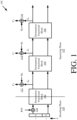
- FIG. 1 there is provided a schematic illustration of an illustrative architecture for a sponge construction 100 implementing the present solution.
- the sponge construction 100 uses a unique permutation function f (described below) to provide the traditional suite of cryptographic modes. This will become more evident as the discussion progresses.
- the sponge construction 100 is generally designed to implement symmetric cryptography functionalities, namely key derivation and message encryption/decryption.
- the sponge construction 100 is a simple iterated construction for building a function F based on a unique permutation function f .
- the function F has a variable-length input and an arbitrary output length.
- the capacity c determines the security level of the sponge construction.
- the sponge construction 100 can be implemented in hardware, software or a combination of both hardware and software.
- the operations of each functional block 102-106 may be implemented using hardware and/or software.
- the hardware can include, but is not limited to an electronic circuit.
- the electronic circuit can include passive components, active components and logical components.
- the sponge construction 100 is divided into two phases.
- the first phase is an absorbing phase 120 in which the cryptographic key K or K ⁇ N (i.e., a concatenation of the cryptographic key K and a flag N ) is absorbed into a state of the sponge construction 100 while interleaving with applications of the underlying permutation function f .
- Such absorption is achieved by combining K (or K ⁇ N ) with the first r bits of the initialized state bits b .
- the bits b e.g., 512 bits
- the present solution is not limited in this regard.
- the bits b (e.g., 512 bits) may alternatively be initialized to any bit value (e.g., any 512 bit value). As such, each user could generate its own unique value to set during the initialization phase.
- K or K ⁇ N
- XOR exclusive OR
- XOR operations are well known in the art, and therefore will not be described in detail here. Still, it should be understood that the XOR operations are performed on a bit-by-bit basis. The result of each XOR operation is true whenever an odd number of inputs are true and false whenever an even number of inputs are true. The results of the XOR operations are then passed to permutation functional block 102 where the results are interleaved with applications of the unique permutation function f .
- the second phase is a squeezing phase 122 in which keystream blocks Z 0 , Z 1 , Z 2 are produced by the performance of the unique permutation function f in permutation functional blocks 102-106.
- Each keystream block Z 0 , Z 1 , Z 2 comprises r bits.
- the unique permutation function f will be described in detail below. Still, it should be understood that the permutation function f maps each possible value of the bits input thereto into a particular unique value of the output bits.
- permutation functional block 102 takes the output of the absorbing phase 120 as an input.
- Permutation functional block 104 takes the output of permutation functional block 102 as an input.
- Permutation functional block 106 takes the output of permutation functional block 104 as an input.
- the keystream blocks Z 0 , Z 1 , Z 2 are used to encrypt a message M .
- the keystream blocks Z 0 , Z 1 , Z 2 can be truncated to a desired length l .
- the message M may be padded to make it a multiple of r (if it is not a multiple of r ).
- the message M is parsed into a plurality of message blocks M 0 , M 1 , M 2 .
- Each message block M 0 , M 1 , M 2 comprises a plurality of bits of the message M .
- Each keystream block is then combined with a respective message block so as to produce an encrypted data block.
- the encrypted data block can include, but is not limited to, a ciphertext block C 0 , C 1 or C 2 .
- the present solution is described herein in relation to ciphertext.
- the present solution is not limited in this regard.
- the present solution can be used to encrypt any type of data (e.g., text, audio, video, etc).
- each keystream block Z 0 , Z 1 , Z 2 is combined with a respective block of message bits M 0 , M 1 , M 2 via modulo 2 addition.
- the modulo 2 addition can be implemented using an XOR operation, as shown in FIG. 1 .
- the XOR operation is performed on a bit-by-bit basis.
- a first bit m 0 of a message block M 0 , M 1 or M 2 is combined with a first bit z 0 of a respective keystream block Z 0 , Z 1 or Z 2 via modulo 2 addition.
- a second bit m 1 of a message block M 0 , M 1 or M 2 is combined with a first bit z 1 of a respective keystream block Z 0 , Z 1 or Z 2 via modulo 2 addition, and so on.
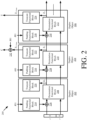
- the duplex construction 200 is an adaptation of the sponge construction framework that, together with the unique permutation function f (described below), provides an additional Authenticated Encryption (“AE”) cryptographic mode. This mode allows both source and integrity verification of encrypted traffic. This will become more evident as the discussion progresses.
- AE Authenticated Encryption
- the duplex construction 200 can be implemented in hardware, software or a combination of both hardware and software.
- the operations of each component 202-232 may be implemented using hardware and/or software.
- the hardware can include, but is not limited to an electronic circuit.
- the electronic circuit can include passive components, active components and logical components.
- the duplex construction 200 the absorbing phase and squeezing phase are combined into each of a plurality of duplex operations. Accordingly, the duplex construction 200 comprises a plurality of duplex objects 202-206 . The operations of each duplex object will be described separately below. Notably, the state of each duplex object call is preserved.
- the input to duplex object 202 is a cryptographic key K (or optionally K ⁇ 1 , i.e. a concatenation of the cryptographic key K and a flag 1 ).
- the cryptographic key K (or optionally K ⁇ 1 ) is padded in padding functional block 214 to make it a multiple of r (if it is not a multiple ofr).
- the padding can involve appending bits to the beginning or end of the cryptographic key K (or optionally K ⁇ 1 ).
- the output of padding functional block 214 is then combined with the first r bits of the initialized state bits b .
- the present solution is not limited in this regard.
- the bits b (e.g., 512 bits) may alternatively be initialized to any bit value (e.g., a 512 bit value). As such, each user could generate its own unique value to set during the initialization phase.
- the combining of the padding functional block output and the first r bits of the initialized state can be achieved via XOR operations 110 , as shown in FIG. 1 .
- XOR operations are well known in the art, and therefore will not be described in detail here. Still, it should be understood that the XOR operations are performed on a bit-by-bit basis.
- the results of the XOR operations are then passed to permutation functional block 208 .
- permutation functional block 208 the unique permutation function f is performed using the results of the XOR operations as inputs so as to generate a keystream block Z 0 .
- the keystream block Z 0 is then truncated to a desired length l , as shown by truncate functional block 220 .
- the value of l here can be less than r.
- the input to duplex object 204 is authentication data A (or optionally A ⁇ 0 , i.e. a concatenation of authentication data A and a flag 0 ).
- the authentication data A can include but is not limited to, authenticated packet headers.
- the authentication data A (or optionally A ⁇ 0 ) is padded in padding functional block 216 to make it a multiple of r (if it is not a multiple of r ).
- the padding of padding functional block 216 is the same as or similar to that of padding functional block 214 .
- the output of padding functional block 216 is then combined with keystream block Z 0 . This combining can be achieved via XOR operations 228 , as shown in FIG. 2 .
- XOR operations are well known in the art, and therefore will not be described in detail here. Still, it should be understood that the XOR operations are performed on a bit-by-bit basis.
- the results of the XOR operations are then passed to permutation functional block 210 .
- the unique permutation function f is performed so as to generate a keystream block Z 1 .
- the keystream block Z 1 is then optionally truncated to a desired length l , as shown by truncate functional block 222 .
- the value of l here can be less than r . Truncation may be performed when the number of bits contained in the message body B is less than r . In this case, the value of l equals the number of bits contained in the message body B .
- the truncated keystream block Z 1-Trunc is output from duplex object 204 .
- the truncated keystream block Z 1-Trunc is combined with a message body B (or optionally B ll 1 , i.e. a concatenation of message body B and a flag 1 ).
- the message body B can include, but is not limited to, packet payload.
- This combining is achieved via XOR operations 232 , which produces encrypted data (e.g., ciphertext) C .
- the XOR operations 232 are performed on a bit-by-bit basis.
- the input to duplex object 206 is message body data B (or optionally B ⁇ 1 ).
- the message body data B can include but is not limited to, packet payload data.
- the message body data B (or optionally B ⁇ 1 ) is padded in padding functional block 218 to make it a multiple of r (if it is not a multiple of r ).
- the padding of padding functional block 218 is the same as or similar to that of padding functional blocks 214 and 216 .
- the output of padding functional block 218 is then combined with keystream block Z 1 . This combining can be achieved via XOR operations 230 , as shown in FIG. 2 . XOR operations are well known in the art, and therefore will not be described in detail here.
- the XOR operations are performed on a bit-by-bit basis.
- the results of the XOR operations are then passed to permutation functional block 212 .
- the unique permutation function f is performed so as to generate a keystream block Z 2 .
- the keystream block Z 2 is then optionally truncated to a desired length l , as shown by truncate functional block 224 .
- the value of l here can be less than r .
- the truncated keystream block Z 2-Trunc is output from duplex object 204.
- the truncated keystream block Z 2-Trunc is then used as an authentication tag T .
- the encrypted data (e.g., ciphertext) C and the authentication tag T would be transmitted from a source communication device to a destination communication device.
- the cryptographic key K would not be transmitted since it would be known by both devices.
- duplex construction 200 The advantages of the duplex construction 200 are that: a single cryptographic key is required; encryption and authentication requires only a single pass; intermediate tags are supported thereby; additional authentication data (e.g., packet headers) is supported thereby; it is secure against generic attacks; and the ability to trade off speed and security by adjusting the value of r .
- FIG. 3 there is provided a schematic illustration that is useful for understanding the unique permutation function f of the present solution which is employed in the sponge and duplex constructions described above in relation to FIGS. 1-2 .
- the permutation functionf supports any key size (e.g., 128 bits or 256 bits) and is bijective. Since the permutation function f is bijective, f - 1 (inverse of f ) exists by definition. While f - 1 is not used in practice, it may be helpful for crypto-analysis and verification purposes. Notably, the number of bits that are input and/or output from the permutation function f is also customizable.
- the permutation function f comprises a round function f round that is iterated R times, depending on the key size.
- the round function f round consists of the following layers: a substitution layer 302 ; a permutation layer 304 ; a mixing layer 306 ; and a round constant addition layer 308 .
- the substitution layer 302 the bits input thereto are substituted with first substitute bits in accordance with a particular transformation and/or mapping algorithm. For example, input bits 010001 are substituted with bits 1010.
- the number of bits input/output to/from the substitution layer 302 can be the same or different.
- the permutation layer 304 the bits input thereto are re-arranged.
- the mixing layer 306 At least two outputs of the permutation layer are combined together.
- the round constant addition layer 308 a constant is added to the output of the mixing layer. The manners in which the operations of each layer 302-308 are achieved will be discussed in detail below.
- R is a customizable element of the permutation function f .
- R is determined by (1) calculating the number of rounds needed for linear and differential crypto-analysis and (2) adding some buffer to increase the security margin.
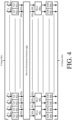
- the substitution layer 302 comprises a plurality of identical substitution boxes (or S-boxes) 402 1 , 402 2 , 402 3 , 402 4 , ..., 402 31 , 402 32 which collectively receive N input bits (e.g., 512 input bits) and individually receive X bits of the N input bits (e.g., 16 bits of 512 input bits).
- N input bits e.g., 512 input bits
- X bits of the N input bits e.g., 16 bits of 512 input bits
- the value of N is selected to be large enough to keep a cryptographic key secure.
- the value of N is selected to be 512 bits for a cryptographic key having a size of 128 bits or 256 bits.
- S-boxes The purpose of the S-boxes is to perform substitution so as to obscure the relationship between the cryptographic key and encrypted data (e.g., ciphertext).
- S-boxes are well known in the art, and therefore will not be described in detail herein. Any known or to be known S-box can be used herein without limitation provided that the following properties are satisfied thereby.
- each S-box comprises a bijective 16-bit-to-16-bit S-box.
- An illustrative architecture for such an S-box is described in Appendix C of a document entitled “Large Substitution Boxes with Efficient Combinational Implementations” which was written by Wood and published in August 2013.
- Each S-box of the substitution layer 302 is computed by the following mathematical equation.
- S x A ⁇ x ⁇ 1 + b
- x is a multi-bit input (e.g., a 16 bit input)
- A is a multi-bit invertible matrix (e.g., a 16 ⁇ 16-bit invertible matrix)
- b is a multi-bit matrix (e.g., a 16 bit matrix).
- Input x is an element of a finite field GF ( 2 16 )/ p ( x ) , where p ( x ) is the irreducible polynomial x 16 + x 5 + x 3 +x + 1 .
- x -1 is then treated as a 16-bit vector, and the affine transformation A ⁇ x -1 + b is computed yielding a 16-bit output S ( x ).
- the forward S-box function is re-written as follows.
- the S-box is customizable by changing the polynomial p ( x ).
- the polynomial can be changed by inputting a new polynomial or selecting a polynomial from a plurality of pre-programmed polynomials. In the latter case, the polynomial can be randomly selected from the plurality of pre-programmed polynomials.
- the random selection can be achieved in accordance with a chaotic, random or pseudo-random number algorithm. Chaotic, random and pseudo-random number algorithms are well known in the art, and therefore will not be described herein. Any known or to be known chaotic, random or pseudo-random number algorithm can be used herein without limitation.
- the S-box is customizable by specifying values of the invertible matrix A and/or the vector b , such that the S-box meets the following criteria.
- the values of the invertible matrix A and/or the vector b are selected randomly. This selection is achieved by selecting values thereof in accordance with a chaotic, random or pseudo-random number algorithm. Any known or to be known chaotic, random or pseudo-random number algorithm can be used herein without limitation.
- a user performs a user-software interaction to select at least one of a plurality of chaotic, random or pseudo-random algorithms that is to be used to generate values for the invertible matrix A and/or the vector b .
- the same or different algorithm can be used to generate numbers for the invertible matrix A and the vector b .
- the user may also enter or select values for parameters of the selected chaotic, random or pseudo-random algorithm(s).
- the present solution is not limited to the particulars of this example.
- the present solution is also not limited to the particulars of the above discussion.
- any S-box configuration can be employed where there is an N bit input (e.g., 16 bit) to an N bit output (e.g., 16 bit) mapping that meets the above listed criteria.
- N bit input e.g., 16 bit
- N bit output e.g., 16 bit
- the present solution is implemented using four 4-bit mappings, rather than one 16-bit to 16-bit mapping.
- the permutation layer 304 comprises a bitwise permutation function 404 .
- the purpose of the bitwise permutation function 404 is to permute or change a bit position of each bit 410 1 , 410 2 , 410 3 , 410 4 , ..., 410 31 , 410 32 input thereto relative to all other bits input thereto.
- Bitwise permutation functions are well known in the art, and therefore will not be described in detail herein. Any known or to be known bitwise permutation function can be used herein without limitation provided that the following properties are satisfied thereby.
- the bitwise permutation function 404 comprises an affine function defined by the following mathematical equation.
- ⁇ x ax + ⁇ mod 512
- ⁇ ( x ) represents the output bit position ( ⁇ (x) ⁇ 511)
- ⁇ is an integer constant (e.g., 31)
- x represents the input bit position (0 ⁇ x )
- ⁇ is an integer constant (e.g., 15).
- bitwise permutation function 404 is customized by changing the permutation formula, but meeting the following criteria.
- the mixing layer 306 comprises a mixing function that is implemented via a plurality of mixers 406 1 , 406 2 , ..., 410 16 .
- one mixer is provided for every two S-boxes.
- the present solution is not limited in this regard.
- the particular number of S-boxes per mixer is customizable.
- the mixing function is a customizable element of the present solution. The purpose of the mixing function is to provide local diffusion (i.e., across two words) and increase the linear and differential branch numbers of a round from two to three.
- mixers based on matrix multiplication in Galois Field GF(2 M ) may be employed because they satisfy all of the following constraints: the matrix is invertible in GF(2 16 )/ ⁇ p ( x )>; the matrix has a differential and linear branch number equal to three; and the transformation is efficiently implementable in hardware.
- each mixer 406 1 , 406 2 , ..., 410 16 is defined by the following mathematical equation.
- p x x 16 + x 5 + x 3 + x 2 + 1
- the mixer takes in two words W 1 and W 2 as input and produces outputs W' 1 and W' 2 as follows.
- W ′ 1 W ′ 2 1 x x x + 1 W 1 W 2
- the mixer is implementable in hardware.
- An illustrative hardware implementation of the mixer is provided in FIG. 5 . As shown in FIG. 5 , the mixer comprises XOR gates 502, 506, 510 and Galois field multipliers 504, 508.
- the Galois field multipliers 504, 508 perform multiplication by x in Galois field GF(2 X ).
- the mixing layer 306 is customizable based on user input. As noted above, each mixer in the mixing layer 306 has two 16-bit input words W 1 , W 2 and two 16-bit output words W' 1 , W' 2 .
- arithmetic in Galois field GF(2 16 ) / p(x) is performed using a certain degree-16 irreducible polynomial p(x) .
- Each 16-bit quantity is treated as a vector of coefficients of a polynomial in x , from x 15 down to x 0 . Addition and multiplication are performed on polynomials using GF(2) arithmetic on the coefficients. Every result is reduced modulo p ( x ) .
- a 128-bit CAM register setting is used to specify a particular irreducible polynomial p(x) used in each mixer.
- the eight CAM register bits are used to select a predefined irreducible polynomial from a given pre-programmed set of irreducible polynomials (e.g., 256).
- a user inputs a bit string of 128 bits (i.e., 8 bits by 16 mixers). The bit string is then processed to parse out sixteen segments each comprising eight bits.
- Each segment is converted or translated into irreducible polynomial coefficient values and/or an identifier for a particular irreducible polynomial of the pre-programmed set.
- the identifier can comprise (1) information identifying the particular irreducible polynomial and/or (2) information indicating where the particular irreducible polynomial of the pre-programmed set is stored in a data store (e.g., memory 812 of FIG. 8 ) local to the electronic device implementing the cryptographic algorithm.
- a table lookup can be used here to perform the bit-to-coefficient conversion/translation and/or the bit-to-identifier conversion/translation.
- the set of irreducible polynomials (e.g., 256) is selected at the factory from the 4,080 different 16-degree polynomials. Accordingly, a different set of irreducible polynomials (e.g., 256) can be selected for each customer to achieve customization of the cryptographic algorithm, i.e., a new set of predefined irreducible polynomials (e.g., 256) can be from the 4,080 different 16-degree polynomials for each customer.
- the bit string is entered by the user in the field.
- the bit string includes arbitrary bits.
- the user has no expertise with regard to cryptography. Still, the user is able to change the encryption/decryption algorithm without causing any degradation to the security thereof.
- the round constant addition layer 308 comprises a plurality of addition operations represented by blocks 408 1 , 408 2 , 408 3 , 408 4 ,..., 408 31 , 408 32 .
- the purpose of the addition operations is to add a constant N bit value to the state using bitwise XOR in order to disrupt symmetry and prevent slide attacks.
- the round constant must be fixed random N-bit values.
- Each round i must use a different round constant.
- the round constant is customizable, and should be unique for each round to prevent against slide attacks and be random, pseudorandom or highly asymmetric to reduce symmetry in the state. Accordingly, the round constant addition layer 308 is customizable by simply choosing different round constants, but meeting the following criteria.
- the round constant RC i for round i is given by the following mathematical equation.
- R C i KECCAK ⁇ N ASCII i
- ASCII( i ) is a function that provides a one or two byte ASCII representation of round i
- KECCAK-512 is the hash function that outputs an N (e.g., 512) bit message digest.
- N e.g., 512
- the present solution is suitable for implementation on Field Programmable Gate Arrays ("FPGAs").
- FPGAs Field Programmable Gate Arrays
- Serial and fully parallel implementations can be used to meet area or performance constraints.
- the S-boxes may be implemented using composite field techniques and pipelined for higher performance.
- the present solution can be integrated into Single Chip Crypto (“SCC”) systems.
- Post Quantum Security will become a requirement for radio product customers, as well as provable computational security and quantified theoretical security metrics and analysis processes.
- the present solution provides a security means that satisfies all of these requirements.
- the present algorithm is highly customizable within a security margin. This customizability is useful in cases where different users want unique, proprietary algorithms.
- the following features of the present solution are customizable: (1) the state initialization; (2) the number of rounds R ; (3) the permutation function f ; (4) the number of bits N input into the round function; (5) the type, number, parameters and mapping function of the S-boxes; (6) the bitwise permutation function; (7) the mixing function; and (8) the round constants.
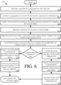
- Method 600 begins with step 602 and continues with optional step 604.
- a cryptographic key is concatenated with a flag value.
- the cryptographic key is combined with state initialization bits to generate the first combination bits.
- a multi-bit value for the state initialization bits may be selected such that it is unique for a given application.
- the first combination bits are then used to produce a first keystream, as shown by step 608 .
- the first keystream may optionally be truncated to a desired length, as shown by step 610 .
- the first keystream is produced using a permutation function f .
- the permutation function f is performed using the first combination bits as inputs thereof.
- the permutation function f comprises a round function f round that is iterated R times.
- the round function f round consists of (1) a substitution layer in which the first combination bits are substituted with substitute bits, (2) a permutation layer in which the substitute bits are re-arranged, (3) a mixing layer in which at least two outputs of the permutation layer are combined together, and (4) an addition layer in which a constant is added to the output of the mixing layer.
- Step 612 involves padding the first data to make a total number of bits contained therein a multiple of the total number of state initialization bits prior to being encrypted.
- the first data is then encrypted using the first keystream, as shown by step 614 .
- the first data may be combined with the first keystream using modular arithmetic (e.g., modulo 2 addition).
- the first data comprises, but is not limited to, authentication data and/or message body data.
- Step 618 involves producing a second keystream by performing the permutation function f using the first keystream as inputs thereto.
- Step 620 involves using the second keystream to encrypt the second data so as to produce the second encrypted data (e.g., ciphertext).
- method 600 ends or other processing is performed (e.g., repeat steps 618-620 for a next block of message data), as shown by step 628 .
- steps 622-626 are performed.
- the first encrypted data e.g., ciphertext
- the second keystream is also used in step 622 to produce the third combination bits.
- the third combination bits are input into the permutation function f , as shown by step 624 .
- a third keystream is produced. At least a portion of the third keystream is used as an authentication tag.
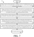
- FIG. 7 is a flow diagram of an illustrative method 700 for customizing a permutation function f .
- the customization changes the permutation function f without degenerating a security of the encryption/decryption algorithm.
- FIG. 7 includes a plurality of blocks 704-712 to illustrate that the permutation function f can be customized in various ways.
- FIG. 7 can be modified to eliminate any of the blocks or to show certain block as optional blocks.
- the present solution is not limited to the order in which the blocks are shown in FIG. 7 .
- block 712 can reside before block 710 .
- method begins with 702 and continues with 704 where a first user-software interaction is performed to customize an S-box (e.g., S-box 402 1 , ..., or 402 32 of FIG. 4 ) of a substitution layer (e.g., substitution layer 302 of FIG. 3 ).
- S-box e.g., S-box 402 1 , ..., or 402 32 of FIG. 4
- a substitution layer e.g., substitution layer 302 of FIG. 3
- the customization is achieved by changing a polynomial equation and/or by changing an input-to-output bit mapping, such that the S-box (1) has input values and output values that are all different, (2) does not have an output value that is equal to the corresponding input value, (3) does not have an output value that is a bitwise complement of the corresponding input value, (4) has a maximum differential probability of 2 -14 or smaller, and (5) has a maximum linear bias of 2 -8 or smaller.
- the values may be randomly selected in accordance with a chaotic, random or pseudo-random number algorithm.
- the same or different chaotic, random or pseudo-random number algorithm can be used to specify values for the multi-bit invertible matrix A and the multi-bit vector b .
- the first user-software interaction can be achieved using an input device (e.g., a touch screen 854 of FIG. 8 , a keypad 850 of FIG. 8 , a mouse, a drop down menu or any other input means) provided by a computing device (such as that shown in FIG. 8 ).
- a permutation formula is changed for a bitwise permutation function of a permutation layer (e.g., permutation layer 304 of FIG. 3 ).
- This change can be achieved by performing a second user-software interaction to (a) select a permutation formula from a plurality of predefined permutation formulas, or (b) enter a unique permutation formula that is not included in the plurality of predefined permutation formulas.
- each output bit of a given S-box goes to a different mixer's input bit; (2) bit positions of bits input to the permutation layer are different than the positions of corresponding bits output from the permutation layer; and (3) an order of each bit position is greater than a number of rounds in a bijective function.
- the second user-software interaction can be achieved using a touch screen, a key pad, a mouse, a drop down menu or any other input means provided by a computing device (such as that shown in FIG. 8 ).
- a third user-software interaction is performed to select a set of irreducible polynomial equations from a plurality of polynomial equations.
- the selected set is pre-program for possible use by mixers (e.g., mixers 406 1 , ..., 406 16 of FIG. 4 ) of a mixing layer (e.g., mixing layer 306 of FIG. 3 ).
- mixers e.g., mixers 406 1 , ..., 406 16 of FIG. 4
- a mixing layer e.g., mixing layer 306 of FIG. 3
- each of the plurality of polynomial equations comprises a degree-16 irreducible polynomial equation.
- a fourth user-software interaction is performed in 710 to select, for each mixer of the mixing layer, an irreducible polynomial p(x) from the pre-programmed set of irreducible polynomials.
- This selecting can be achieved by: receiving a first user-software interaction for entering a first bit string comprising a plurality of first arbitrary bits; breaking the first bit string into a plurality of equal length segments each comprising only a portion of the plurality of first bits; and converting/translating each of the equal length segments into irreducible polynomial coefficients into irreducible polynomial coefficients and/or an irreducible polynomial identifier, as described above.
- a respective mixer of the mixing layer is caused to use the irreducible polynomial coefficients and/or the identified irreducible polynomial.
- the third user-software interaction of 708 is performed at the factory, while the fourth user-software interaction of 710 is performed in the field.
- a fifth user-software interaction is performed to cause the selection of a round constant to be employed in a round constant addition layer (e.g., round constant addition layer 308 of FIG. 3 ).
- the selection is made such that (1) there is no identifiable pattern in a plurality of round constant values and (2) the round constant values are different for each round.
- each round constant value of the plurality of round constant values has the same number of 0's and 1's, and/or is chosen at random.
- 714 is performed where method 700 ends or other processing is performed.
- the computing device 800 is generally configured to allow a cryptographic algorithm to be customized (and more particularly a permutation function f as described above).
- the computing device 800 implements the cryptographic algorithm and/or is able to communicate with another electronic device (e.g., a communications device, such as a handheld radio) implementing the cryptographic algorithm.
- a communications device such as a handheld radio
- the computing device 800 may include more or less components than those shown in FIG. 8 . However, the components shown are sufficient to disclose an illustrative embodiment implementing the present solution.
- the hardware architecture of FIG. 8 represents one embodiment of a representative server configured to facilitate inventory counts and management. As such, the computing device 800 of FIG. 8 implements at least a portion of a method for customizing a permutation function f .
- the hardware includes, but is not limited to, one or more electronic circuits.
- the electronic circuits can include, but are not limited to, passive components (e.g., resistors and capacitors) and/or active components (e.g., amplifiers and/or microprocessors).
- the passive and/or active components can be adapted to, arranged to and/or programmed to perform one or more of the methodologies, procedures, or functions described herein.
- the computing device 800 comprises a user interface 802 , a CPU 806 , a system bus 810 , a memory 812 connected to and accessible by other portions of computing device 800 through system bus 810 , and hardware entities 814 connected to system bus 810 .
- the user interface can include input devices (e.g., a keypad 850 ) and output devices (e.g., speaker 852 , a display 854 , and/or light emitting diodes 856 ), which facilitate user-software interactions for controlling operations of the computing device 800 .
- Hardware entities 814 perform actions involving access to and use of memory 812 , which can be a RAM, a disk driver and/or a Compact Disc Read Only Memory (“CD-ROM").
- Hardware entities 814 can include a disk drive unit 816 comprising a computer-readable storage medium 818 on which is stored one or more sets of instructions 820 (e.g., software code) configured to implement one or more of the methodologies, procedures, or functions described herein.
- the instructions 820 can also reside, completely or at least partially, within the memory 812 and/or within the CPU 806 during execution thereof by the computing device 800 .
- the memory 812 and the CPU 806 also can constitute machine-readable media.
- machine-readable media refers to a single medium or multiple media (e.g., a centralized or distributed database, and/or associated caches and servers) that store the one or more sets of instructions 820 .
- machine-readable media also refers to any medium that is capable of storing, encoding or carrying a set of instructions 820 for execution by the computing device 800 and that cause the computing device 800 to perform any one or more of the methodologies of the present disclosure.
- the hardware entities 814 include an electronic circuit (e.g., a processor) programmed for facilitating the customization of a cryptographic algorithm.
- the electronic circuit can access and run a software application 822 installed on the computing device 800 .
- the software application 822 is generally operative to facilitate: a first user-software interaction to customize an S-box of a substitution layer by randomly specifying values of an invertible matrix A and a vector b ; a second user-software interaction to (a) select a permutation formula from a plurality of predefined permutation formulas, or (b) enter a unique permutation formula that is not included in the plurality of predefined permutation formulas; a third user-software interaction to select an irreducible polynomial p ( x ) from a plurality of irreducible polynomials to be used in each mixer of a mixing layer; and/or a fourth user-software interaction to cause the random selection of at least one round constant to be employed in a round constant addition layer, where each bit in the selected round constant is a 0 or 1 with probability 0.5.
- Other functions of the software application 822 are apparent from the above discussion.
Landscapes
- Engineering & Computer Science (AREA)
- Computer Security & Cryptography (AREA)
- Computer Networks & Wireless Communication (AREA)
- Signal Processing (AREA)
- Physics & Mathematics (AREA)
- General Physics & Mathematics (AREA)
- Theoretical Computer Science (AREA)
- Mobile Radio Communication Systems (AREA)
Description
- This document relates generally to cryptographic systems. More particularly, this document relates to cryptographic systems implementing a customizable encryption algorithm.
- There are many cryptographic algorithms known in the art. One such cryptographic algorithm is described in
U.S. Patent No. 9,438,416 to Kurdziel
DocumentUS2007071236 discloses a method and system to encrypt and decrypt data. The method disclosed therein comprises providing input data to be encrypted, said input data made up of a plurality of sub-data, each said sub-data comprising sequence of bits of data; dynamically selecting a plurality of invertible encryption parameters; and performing one or more rounds of a combination of data modification, sequence modification and data-sequence modification using plurality of selected encryption parameters deriving encrypted data. The system includes a processor for executing code for dynamically selecting a plurality of invertible encryption parameters.
DocumentUS2012237020 discloses a key variable loader that receives a set of Rijndael parameters that were verified using a simulation computer, wherein the set of Rijndael parameters provide an input for implementing at least one step of the Rijndael block cipher and when used with a secret key allow a conversion between plain text and cipher text using the Rijndael block cipher. The key variable loader further stores the set of Rijndael parameters and subsequently provides the set of Rijndael parameters to a device having a customizable Rijndael block cipher, like a subscriber unit or a key management facility. DocumentUS2012/237020A1 further discloses a SubBytes transform, which a non-linear substitution step where each byte is replaced with another according to an S-box (substitution box) that is in standard AES a lookup table configurable based upon the Rijndael parameters provided at the input. INDRAJIT DAS ET AL: "Random S-Box generation in AES by changing irreducible polynomial",COMMUNICATIONS, DEVICES AND INTELLIGENT SYSTEMS (CODIS), 2012 INTERNATIONAL CONFERENCE ON, IEEE, 28 December 2012 (2012-12-28), pages 556-559, discloses random S-Box Generation in AES by changing irreducible polynomial. The document discloses an algorithm, which make use of different irreducible polynomial to finite field of GF (28) to make random S-Box and Inverse S-Box. KELLY MATTHEW ET AL: "Customizable sponge-based authenticated encryption using 16-bit S-boxes", MILCOM 2015 - 2015 IEEE MILITARY COMMUNICATIONS CONFERENCE, IEEE, 26 October 2015 (2015-10-26), pages 43-48, discloses a sponge function based on an SPN network that can be customized at several levels: initialization, S-Box, permutation, mixing layer and constant to be added. - The present disclosure concerns implementing systems and methods for customizing a cryptographic algorithm (e.g., an encryption algorithm and/or a decryption algorithm). The customization of the cryptographic algorithm does not cause any degeneration of its security. The invention is defined by the independent claim. The methods comprise:
providing an electronic device with the cryptographic algorithm implementing a permutation function f configured to produce a first keystream using bits input thereto, the permutation function f comprising a round function fround consisting of a mixing layer in which input bits are combined together; and customizing the mixing layer of the permutation function f while the electronic device is in the field. The mixing layer is customized by: receiving, by the electronic device, a first user-software interaction for entering a first bit string comprising a plurality of first arbitrary bits; breaking the first bit string into a plurality of equal length segments each comprising only a portion of the plurality of first bits; translating each of the equal length segments into irreducible polynomial coefficients; and causing a respective one of a plurality of mixers comprising the mixing layer to use the irreducible polynomial coefficients. - The methods further comprise: receiving a second user-software interaction for selecting a set of irreducible polynomial equations from a plurality of polynomial equations; and programming the selected set of irreducible polynomial equations for possible use by the mixers of the mixing layer. Each of the plurality of polynomial equations may comprise a degree-16 irreducible polynomial equation.
- The round function fround further consists of a substitution layer in which input bits are substituted with substitute bits. The bit substitutions of the substitution layer are performed by a plurality of customizable S-boxes. At least one S-box of the plurality of customizable S-boxes is customized by changing a polynomial equation and/or by changing an input-to-output bit mapping, such that the S-box: (1) has input values and output values that are all different; (2) does not have an output value that is equal to the corresponding input value; (3) does not have an output value that is a bitwise complement of the corresponding input value; (4) has a maximum differential probability of 2-14 or smaller; and (5) has a maximum linear bias of 2-8 or smaller. For example, the input-to-output bit mapping is changed by specifying values of at least one of a multi-bit invertible matrix A and a multi-bit vector b for the mathematical equation S(x) = A·x-1 + b, where x is a multi-bit input. The values may be randomly selected in accordance with a chaotic, random or pseudo-random number algorithm. The same or different chaotic, random or pseudo-random number algorithm is used to specify values for the multi-bit invertible matrix A and the multi-bit vector b. The present solution is not limited to the particulars of this example.
- The round function fround further consists of a customizable permutation layer in which bits are rearranged. The customizable permutation layer is customized by changing a permutation formula such that the following criteria is met: (1) each output bit of a given S-box goes to a different mixer's input bit; (2) bit positions of bits input to the permutation layer are different than the positions of corresponding bits output from the permutation layer; and (3) an order of each bit position is greater than a number of rounds in a bijective function.
- In those or yet other scenarios, the round function fround further consists of a customizable addition layer in which a constant is added to an output of the mixing layer. The customizable addition layer is customized by selecting a plurality of round constant values such that (1) there are no identifiable patterns in the plurality of round constant values and (2) the round constant values are different for each round. Each round constant value of the plurality of round constant values can have the same number of 0's and 1's, and/or be chosen at random.
- The present solution will be described with reference to the following drawing figures, in which like numerals represent like items throughout the figures.
-
FIG. 1 is an illustration of an illustrative sponge construction employing a unique permutation function. -
FIG. 2 is an illustration of an illustrative duplex construction employing a unique permutation function. -
FIG. 3 is an illustration that is useful for understanding the unique permutation function f . -
FIG. 4 is an expanded block diagram of the round function fround shown inFIG. 3 . -
FIG. 5 is a schematic illustration of an illustrative hardware implementation of a mixer. -
FIG. 6 is a flow diagram of an illustrative method for generating encrypted data. -
FIG. 7 is a flow diagram of an illustrative method for customizing a permutation function f . -
FIG. 8 is an illustration of an illustrative computing device that can be used to customize a permutation function f . - It will be readily understood that the components of the embodiments as generally described herein and illustrated in the appended figures could be arranged and designed in a wide variety of different configurations. Thus, the following more detailed description of various embodiments, as represented in the figures, is not intended to limit the scope of the present disclosure, but is merely representative of various embodiments. While the various aspects of the embodiments are presented in drawings, the drawings are not necessarily drawn to scale unless specifically indicated.
- The present solution may be embodied in other specific forms without departing from its spirit or essential characteristics. The described embodiments are to be considered in all respects only as illustrative and not restrictive. The scope of the present solution is, therefore, indicated by the appended claims rather than by this detailed description. All changes which come within the meaning and range of equivalency of the claims are to be embraced within their scope.
- Reference throughout this specification to features, advantages, or similar language does not imply that all of the features and advantages that may be realized with the present solution should be or are in any single embodiment of the present solution. Rather, language referring to the features and advantages is understood to mean that a specific feature, advantage, or characteristic described in connection with an embodiment is included in at least one embodiment of the present solution. Thus, discussions of the features and advantages, and similar language, throughout the specification may, but do not necessarily, refer to the same embodiment.
- Furthermore, the described features, advantages and characteristics of the present solution may be combined in any suitable manner in one or more embodiments. One skilled in the relevant art will recognize, in light of the description herein, that the present solution can be practiced without one or more of the specific features or advantages of a particular embodiment. In other instances, additional features and advantages may be recognized in certain embodiments that may not be present in all embodiments of the present solution.
- Reference throughout this specification to "one embodiment", "an embodiment", or similar language means that a particular feature, structure, or characteristic described in connection with the indicated embodiment is included in at least one embodiment of the present solution. Thus, the phrases "in one embodiment", "in an embodiment", and similar language throughout this specification may, but do not necessarily, all refer to the same embodiment.
- As used in this document, the singular form "a", "an", and "the" include plural references unless the context clearly dictates otherwise. Unless defined otherwise, all technical and scientific terms used herein have the same meanings as commonly understood by one of ordinary skill in the art. As used in this document, the term "comprising" means "including, but not limited to".
- Sponge and duplex constructions provide frameworks representing new cryptographic paradigms with many advantages including processing performance and provable computational cryptographic strength. A novel cryptographic algorithm design is described herein that is based on the sponge and duplex construction frameworks. More particularly, the novel cryptographic algorithm comprises a unique permutation function f that is used with a sponge construction and/or a duplex construction. In this regard, the present solution provides the same advantages of conventional sponge and duplex constructions, as well as other additional advantages. These other additional advantages include, but are not limited to: the provision of a highly configurable and customizable cryptographic algorithm; the provision of a symmetric key algorithm that is designed against a military threat model; the provision of increased throughput suitable to support high-rate networked waveforms; and the provision of an algorithm that can be used with key lengths that are longer than the key lengths which can be used with conventional cryptographic algorithms. Longer key lengths result in a higher level of security.
- For military applications, the customers desire sovereign cryptography. Sovereign cryptography provides a feature called security autonomy where the customers have their own variant of a cryptographic algorithm. One way to obtain security autonomy is for the customers to specify their own cryptographic algorithm to be implemented in the device(s). This solution is not economically feasible. As such, the present solution provides a proprietary cryptographic algorithm that can be customized in various ways. The customization capability mainly lies in two types of customization, namely factory customization and field customization.
- Factory customization is more substantial in terms of changing the cryptographic algorithms structure and adding new algorithm blocks, but also requires one to have the requisite expertise. One disadvantage of factory customization is that human error can cause degradation of the cryptographic system. This disadvantage is addressed by the present solution. In this regard, the present solution employs a cryptographic (e.g., encryption and/or decryption) algorithm that can be customized without any degradation to the security thereof. Another disadvantage is that some customers do not want others (i.e., the people with the requisite expertise) to have knowledge of their own variant of a cryptographic algorithm. The present solution also addressing this disadvantage by providing a cryptographic algorithm that can be customized in the field.
- Field customization allows customers to make changes to the cryptographic algorithm via a tool after the device is provided to them. All possible information that can be input into the system via the tool to provide the field customization are equally valid in terms of not degrading the cryptographic strength of the cryptographic algorithm.
- Accordingly, the present solution has two levels of customization. A first Custom Crypto ("CC") capability allows customized versions of the sponge based cryptographic algorithm to be embedded in a device (e.g., a handheld radio) at the factory. There are a number of CC settings that are specified for a custom version of the sponge based cryptographic algorithm, after an analysis to ensure that it is secure. The CC settings are stored and loaded into the encryption/decryption circuitry at power-on. The CC capability can be implemented in a substitution layer, a permutation layer and/or a round constant addition layer of a permutation function f , as discussed below.
- A second Custom Algorithm Modification ("CAM") capability allows a user to customize the encryption/decryption algorithm in the field after power-on (i.e., after the device employing the cryptographic algorithm has been provided to the customer). CAM settings are stored in an N-bit (e.g., 128 bit) register that can be changed at any time (except during encryption/decryption). All possible CAM register values must yield different, fully secure customized algorithms. CAM is implemented in a mixer layer of the permutation function f . The CC and CAM capabilities will be described in detail below.
- The present solution also has the following additional advantages: increased processing performance and provable computational cryptographic strength; cost effective alternative to embedded sovereign cryptography; includes cryptographic constructs and key lengths to provide post quantum security in a reasonable hardware and software footprint; and designed against a military threat model.
- Referring now to
FIG. 1 , there is provided a schematic illustration of an illustrative architecture for asponge construction 100 implementing the present solution. Notably, thesponge construction 100 uses a unique permutation function f (described below) to provide the traditional suite of cryptographic modes. This will become more evident as the discussion progresses. - As shown in
FIG. 1 , thesponge construction 100 is generally designed to implement symmetric cryptography functionalities, namely key derivation and message encryption/decryption. Thesponge construction 100 is a simple iterated construction for building a function F based on a unique permutation function f . The function F has a variable-length input and an arbitrary output length. The unique permutation function f operates on a state of b = r + c bits, where r (e.g., 128 bits) is the bitrate and c (e.g., 384 bits) is the capacity. The capacity c determines the security level of the sponge construction. - Notably, the
sponge construction 100 can be implemented in hardware, software or a combination of both hardware and software. As such, the operations of each functional block 102-106 may be implemented using hardware and/or software. The hardware can include, but is not limited to an electronic circuit. The electronic circuit can include passive components, active components and logical components. - The
sponge construction 100 is divided into two phases. The first phase is anabsorbing phase 120 in which the cryptographic key K or K ∥ N (i.e., a concatenation of the cryptographic key K and a flag N ) is absorbed into a state of thesponge construction 100 while interleaving with applications of the underlying permutation function f . Such absorption is achieved by combining K (or K ∥ N ) with the first r bits of the initialized state bits b. In some scenarios, the bits b (e.g., 512 bits) are initialized to zero. The present solution is not limited in this regard. The bits b (e.g., 512 bits) may alternatively be initialized to any bit value (e.g., any 512 bit value). As such, each user could generate its own unique value to set during the initialization phase. - The combining of K (or K ∥ N) with the first r bits of the initialized state can be achieved via exclusive OR ("XOR")
operations 110, as shown inFIG. 1 . XOR operations are well known in the art, and therefore will not be described in detail here. Still, it should be understood that the XOR operations are performed on a bit-by-bit basis. The result of each XOR operation is true whenever an odd number of inputs are true and false whenever an even number of inputs are true. The results of the XOR operations are then passed to permutationfunctional block 102 where the results are interleaved with applications of the unique permutation function f. - The second phase is a squeezing
phase 122 in which keystream blocks Z0, Z1, Z2 are produced by the performance of the unique permutation function f in permutation functional blocks 102-106. Each keystream block Z0, Z1, Z2 comprises r bits. The unique permutation function f will be described in detail below. Still, it should be understood that the permutation function f maps each possible value of the bits input thereto into a particular unique value of the output bits. Notably, permutationfunctional block 102 takes the output of theabsorbing phase 120 as an input. Permutationfunctional block 104 takes the output of permutationfunctional block 102 as an input. Permutation functional block 106 takes the output of permutationfunctional block 104 as an input. - Next, the keystream blocks Z0, Z1, Z2 are used to encrypt a message M. In this regard, the keystream blocks Z0, Z1, Z2 can be truncated to a desired length l . Additionally or alternatively, the message M may be padded to make it a multiple of r (if it is not a multiple of r ). The message M is parsed into a plurality of message blocks M0, M1, M2 . Each message block M0, M1, M2 comprises a plurality of bits of the message M. Each keystream block is then combined with a respective message block so as to produce an encrypted data block. The encrypted data block can include, but is not limited to, a ciphertext block C0, C1 or C2 . The present solution is described herein in relation to ciphertext. The present solution is not limited in this regard. The present solution can be used to encrypt any type of data (e.g., text, audio, video, etc...).
- In some scenarios, the combining of the keystream and message blocks is achieved using modular arithmetic. For example, each keystream block Z0, Z1, Z2 is combined with a respective block of message bits M0, M1, M2 via modulo 2 addition. The modulo 2 addition can be implemented using an XOR operation, as shown in
FIG. 1 . The XOR operation is performed on a bit-by-bit basis. As such, a first bit m0 of a message block M0, M1 or M2 is combined with a first bit z0 of a respective keystream block Z0, Z1 or Z2 via modulo 2 addition. Next, a second bit m1 of a message block M0, M1 or M2 is combined with a first bit z1 of a respective keystream block Z0, Z1 or Z2 via modulo 2 addition, and so on. - Referring now to
FIG. 2 , there is provided a schematic illustration of an illustrative architecture for aduplex construction 200 implementing the present solution. Theduplex construction 200 is an adaptation of the sponge construction framework that, together with the unique permutation function f (described below), provides an additional Authenticated Encryption ("AE") cryptographic mode. This mode allows both source and integrity verification of encrypted traffic. This will become more evident as the discussion progresses. - Notably, the
duplex construction 200 can be implemented in hardware, software or a combination of both hardware and software. As such, the operations of each component 202-232 may be implemented using hardware and/or software. The hardware can include, but is not limited to an electronic circuit. The electronic circuit can include passive components, active components and logical components. - In the
duplex construction 200, the absorbing phase and squeezing phase are combined into each of a plurality of duplex operations. Accordingly, theduplex construction 200 comprises a plurality of duplex objects 202-206. The operations of each duplex object will be described separately below. Notably, the state of each duplex object call is preserved. - The input to
duplex object 202 is a cryptographic key K (or optionally K ∥ 1 , i.e. a concatenation of the cryptographic key K and a flag 1 ). The cryptographic key K (or optionally K ∥ 1 ) is padded in paddingfunctional block 214 to make it a multiple of r (if it is not a multiple ofr). The padding can involve appending bits to the beginning or end of the cryptographic key K (or optionally K ∥ 1 ). Next, the output of paddingfunctional block 214 is then combined with the first r bits of the initialized state bits b. In some scenarios, the bits b are initialized to zero, where b = r + c. The present solution is not limited in this regard. The bits b (e.g., 512 bits) may alternatively be initialized to any bit value (e.g., a 512 bit value). As such, each user could generate its own unique value to set during the initialization phase. - The combining of the padding functional block output and the first r bits of the initialized state can be achieved via
XOR operations 110, as shown inFIG. 1 . XOR operations are well known in the art, and therefore will not be described in detail here. Still, it should be understood that the XOR operations are performed on a bit-by-bit basis. The results of the XOR operations are then passed to permutationfunctional block 208. In permutationfunctional block 208, the unique permutation function f is performed using the results of the XOR operations as inputs so as to generate a keystream block Z0 . The keystream block Z0 is then truncated to a desired length l, as shown by truncatefunctional block 220. The value of l here can be less than r. - The input to
duplex object 204 is authentication data A (or optionally A ∥ 0 , i.e. a concatenation of authentication data A and a flag 0 ). The authentication data A can include but is not limited to, authenticated packet headers. The authentication data A (or optionally A ∥ 0 ) is padded in paddingfunctional block 216 to make it a multiple of r (if it is not a multiple of r ). The padding of paddingfunctional block 216 is the same as or similar to that of paddingfunctional block 214. Next, the output of paddingfunctional block 216 is then combined with keystream block Z0 . This combining can be achieved viaXOR operations 228, as shown inFIG. 2 . XOR operations are well known in the art, and therefore will not be described in detail here. Still, it should be understood that the XOR operations are performed on a bit-by-bit basis. The results of the XOR operations are then passed to permutationfunctional block 210. In permutationfunctional block 210, the unique permutation function f is performed so as to generate a keystream block Z1 . The keystream block Z 1 is then optionally truncated to a desired length l , as shown by truncatefunctional block 222. The value of l here can be less than r. Truncation may be performed when the number of bits contained in the message body B is less than r . In this case, the value of l equals the number of bits contained in the message body B. The truncated keystream block Z1-Trunc is output fromduplex object 204. - Thereafter, the truncated keystream block Z1-Trunc is combined with a message body B (or optionally Bll 1 , i.e. a concatenation of message body B and a flag 1 ). The message body B can include, but is not limited to, packet payload. This combining is achieved via
XOR operations 232, which produces encrypted data (e.g., ciphertext) C. TheXOR operations 232 are performed on a bit-by-bit basis. - The input to
duplex object 206 is message body data B (or optionally B ∥ 1 ). The message body data B can include but is not limited to, packet payload data. The message body data B (or optionally B ∥ 1 ) is padded in paddingfunctional block 218 to make it a multiple of r (if it is not a multiple of r ). The padding of paddingfunctional block 218 is the same as or similar to that of paddingfunctional blocks functional block 218 is then combined with keystream block Z1 . This combining can be achieved viaXOR operations 230, as shown inFIG. 2 . XOR operations are well known in the art, and therefore will not be described in detail here. Still, it should be understood that the XOR operations are performed on a bit-by-bit basis. The results of the XOR operations are then passed to permutationfunctional block 212. In permutationfunctional block 212, the unique permutation function f is performed so as to generate a keystream block Z2 . The keystream block Z2 is then optionally truncated to a desired length l , as shown by truncatefunctional block 224. The value of l here can be less than r . The truncated keystream block Z2-Trunc is output fromduplex object 204. The truncated keystream block Z2-Trunc is then used as an authentication tag T. - In a communications scenario, the encrypted data (e.g., ciphertext) C and the authentication tag T would be transmitted from a source communication device to a destination communication device. The cryptographic key K would not be transmitted since it would be known by both devices.
- The advantages of the
duplex construction 200 are that: a single cryptographic key is required; encryption and authentication requires only a single pass; intermediate tags are supported thereby; additional authentication data (e.g., packet headers) is supported thereby; it is secure against generic attacks; and the ability to trade off speed and security by adjusting the value of r. - Referring now to
FIG. 3 , there is provided a schematic illustration that is useful for understanding the unique permutation function f of the present solution which is employed in the sponge and duplex constructions described above in relation toFIGS. 1-2 . The permutation functionf supports any key size (e.g., 128 bits or 256 bits) and is bijective. Since the permutation function f is bijective, f -1 (inverse of f ) exists by definition. While f -1 is not used in practice, it may be helpful for crypto-analysis and verification purposes. Notably, the number of bits that are input and/or output from the permutation function f is also customizable. - The permutation function f comprises a round function fround that is iterated R times, depending on the key size. The round function f round consists of the following layers: a
substitution layer 302; apermutation layer 304; amixing layer 306; and a roundconstant addition layer 308. In thesubstitution layer 302, the bits input thereto are substituted with first substitute bits in accordance with a particular transformation and/or mapping algorithm. For example, input bits 010001 are substituted with bits 1010. The number of bits input/output to/from thesubstitution layer 302 can be the same or different. In thepermutation layer 304, the bits input thereto are re-arranged. In themixing layer 306, at least two outputs of the permutation layer are combined together. In the roundconstant addition layer 308, a constant is added to the output of the mixing layer. The manners in which the operations of each layer 302-308 are achieved will be discussed in detail below. - Notably, R is an integer which has a value large enough to resist differential attacks, linear attacks and other attacks depending on the cryptographic key size (e.g., R=10 for a 128 bit key or R=16 for a 256 bit key). In this regard, R is a customizable element of the permutation function f . In some scenarios, R is determined by (1) calculating the number of rounds needed for linear and differential crypto-analysis and (2) adding some buffer to increase the security margin.
- Referring now to
FIG. 4 , there is provided an expanded block diagram of the round function f round. Thesubstitution layer 302 comprises a plurality of identical substitution boxes (or S-boxes) 4021 , 4022 , 4023 , 4024 , ..., 40231, 40232 which collectively receive N input bits (e.g., 512 input bits) and individually receive X bits of the N input bits (e.g., 16 bits of 512 input bits). The value of N is selected to be large enough to keep a cryptographic key secure. For example, the value of N is selected to be 512 bits for a cryptographic key having a size of 128 bits or 256 bits. - The purpose of the S-boxes is to perform substitution so as to obscure the relationship between the cryptographic key and encrypted data (e.g., ciphertext). S-boxes are well known in the art, and therefore will not be described in detail herein. Any known or to be known S-box can be used herein without limitation provided that the following properties are satisfied thereby.
- (1) The S-boxes have small differential probabilities.
- (2) The S-boxes have small linear approximation biases.
- (3) The S-boxes have a customizable number of input bits X.
- (4) The S-boxes have customizable mapping functions.
- In some scenarios, each S-box comprises a bijective 16-bit-to-16-bit S-box. An illustrative architecture for such an S-box is described in Appendix C of a document entitled "Large Substitution Boxes with Efficient Combinational Implementations" which was written by Wood and published in August 2013. Each S-box of the
substitution layer 302 is computed by the following mathematical equation.
- In this regard, the input to the S-box is represented as a 16-bit column vector x=(x15 x14 ... x1 x0 ) T, x15 is the most significant bit. Using this notation, the forward S-box function is re-written as follows.


- The S-box is customizable by changing the polynomial p ( x ). The polynomial can be changed by inputting a new polynomial or selecting a polynomial from a plurality of pre-programmed polynomials. In the latter case, the polynomial can be randomly selected from the plurality of pre-programmed polynomials. The random selection can be achieved in accordance with a chaotic, random or pseudo-random number algorithm. Chaotic, random and pseudo-random number algorithms are well known in the art, and therefore will not be described herein. Any known or to be known chaotic, random or pseudo-random number algorithm can be used herein without limitation.
- Additionally or alternatively, the S-box is customizable by specifying values of the invertible matrix A and/or the vector b, such that the S-box meets the following criteria.
- Input values of the S-box and the output values of the S-box are all different, where S(x) = x.
- No output value is equal to the corresponding input value.
- No output value is a bitwise complement of the corresponding input value.
- Maximum differential probability of 2-14 or smaller. (Meaning that in theory the amount of work one must do to determine the mapping from input values to output values of the S-box is significantly greater than the time needed for a brute force determination of the key in a given number of rounds.)
- Maximum linear bias of 2-8 or smaller. (Meaning that in theory an attack based on the linear bias of the S-box is not going to be successful if the linear bias has a value less than or equal to 2-8.)
- In some scenarios, the values of the invertible matrix A and/or the vector b are selected randomly. This selection is achieved by selecting values thereof in accordance with a chaotic, random or pseudo-random number algorithm. Any known or to be known chaotic, random or pseudo-random number algorithm can be used herein without limitation.
- For example, in some scenarios, a user performs a user-software interaction to select at least one of a plurality of chaotic, random or pseudo-random algorithms that is to be used to generate values for the invertible matrix A and/or the vector b. The same or different algorithm can be used to generate numbers for the invertible matrix A and the vector b. The user may also enter or select values for parameters of the selected chaotic, random or pseudo-random algorithm(s). The present solution is not limited to the particulars of this example.
- The present solution is also not limited to the particulars of the above discussion. In this regard, it should be understood that any S-box configuration can be employed where there is an N bit input (e.g., 16 bit) to an N bit output (e.g., 16 bit) mapping that meets the above listed criteria. For example, in other scenarios, the present solution is implemented using four 4-bit mappings, rather than one 16-bit to 16-bit mapping.
- The
permutation layer 304 comprises abitwise permutation function 404. The purpose of thebitwise permutation function 404 is to permute or change a bit position of each bit 4101, 4102, 4103, 4104, ..., 41031, 41032 input thereto relative to all other bits input thereto. Bitwise permutation functions are well known in the art, and therefore will not be described in detail herein. Any known or to be known bitwise permutation function can be used herein without limitation provided that the following properties are satisfied thereby. - (1) Each bit 4101, 4102, 4103, 4104, ..., 41031, 41032 permutes to an output bit position different from its input bit position.
- (2) All outputs of a given S-box go to X different mixers.
- (3) The permutation period of the permutation function f exceeds the number of rounds R.
- In some scenarios, the
bitwise permutation function 404 comprises an affine function defined by the following mathematical equation.
- The
bitwise permutation function 404 is customized by changing the permutation formula, but meeting the following criteria. - Each output bit of a given S-box must go to a different mixer's input bit.
- The permutation has no fixed points, where π(x) = x (i.e., bit positions of the input bits are different than the corresponding output bit positions).
- The order of each bit position must be greater than the number of rounds in the bijective function.
- A plurality of permutation formulas which meet the above criteria are described in a thesis document entitled "Design and Cryptoanalysis of a Customizable Authenticated Encryption Algorithm", written by Kelly. Any of the permutation functions mentioned in this thesis can be used herein without limitation. For example, the above-described permutation function is changed to one of the following permutation functions which meet the above criteria.


- The present solution is not limited to the particulars of the permutation formulas referenced above. Any permutation technique can be used here provided that the above listed three criteria are met.
- The
mixing layer 306 comprises a mixing function that is implemented via a plurality of mixers 4061 , 4062 , ..., 41016 . In the scenario shown inFIG. 4 , one mixer is provided for every two S-boxes. The present solution is not limited in this regard. The particular number of S-boxes per mixer is customizable. Also, the mixing function is a customizable element of the present solution. The purpose of the mixing function is to provide local diffusion (i.e., across two words) and increase the linear and differential branch numbers of a round from two to three. In this regard, mixers based on matrix multiplication in Galois Field GF(2M) may be employed because they satisfy all of the following constraints: the matrix is invertible in GF(216)/<p(x)>; the matrix has a differential and linear branch number equal to three; and the transformation is efficiently implementable in hardware. - In some scenarios, operations performed by each mixer 4061 , 4062 , ..., 41016 is defined by the following mathematical equation.


FIG. 5 . As shown inFIG. 5 , the mixer comprisesXOR gates Galois field multipliers 504, 508. TheGalois field multipliers 504, 508 perform multiplication by x in Galois field GF(2X). - The
mixing layer 306 is customizable based on user input. As noted above, each mixer in themixing layer 306 has two 16-bit input words W1, W 2 and two 16-bit output words W'1, W'2 . In themixing layer 306, arithmetic in Galois field GF(216)/p(x) is performed using a certain degree-16 irreducible polynomial p(x) . Each 16-bit quantity is treated as a vector of coefficients of a polynomial in x , from x15 down to x0 . Addition and multiplication are performed on polynomials using GF(2) arithmetic on the coefficients. Every result is reduced modulo p(x). A 128-bit CAM register setting is used to specify a particular irreducible polynomial p(x) used in each mixer. There are sixteen mixers 4061, ..., 40616 so there are eight CAM register bits per mixer. The eight CAM register bits are used to select a predefined irreducible polynomial from a given pre-programmed set of irreducible polynomials (e.g., 256). In this regard, a user inputs a bit string of 128 bits (i.e., 8 bits by 16 mixers). The bit string is then processed to parse out sixteen segments each comprising eight bits. Each segment is converted or translated into irreducible polynomial coefficient values and/or an identifier for a particular irreducible polynomial of the pre-programmed set. The identifier can comprise (1) information identifying the particular irreducible polynomial and/or (2) information indicating where the particular irreducible polynomial of the pre-programmed set is stored in a data store (e.g.,memory 812 ofFIG. 8 ) local to the electronic device implementing the cryptographic algorithm. A table lookup can be used here to perform the bit-to-coefficient conversion/translation and/or the bit-to-identifier conversion/translation. - Notably, there are 4,080 different 16-degree irreducible polynomials that meet the above-listed criteria. The set of irreducible polynomials (e.g., 256) is selected at the factory from the 4,080 different 16-degree polynomials. Accordingly, a different set of irreducible polynomials (e.g., 256) can be selected for each customer to achieve customization of the cryptographic algorithm, i.e., a new set of predefined irreducible polynomials (e.g., 256) can be from the 4,080 different 16-degree polynomials for each customer.
- In some scenarios, at least two of the mixers use the same irreducible polynomial, but with different coefficients. Additionally or alternatively, the bit string is entered by the user in the field. The bit string includes arbitrary bits. The user has no expertise with regard to cryptography. Still, the user is able to change the encryption/decryption algorithm without causing any degradation to the security thereof.
- The round
constant addition layer 308 comprises a plurality of addition operations represented by blocks 4081, 4082, 4083, 4084,..., 40831, 40832. The purpose of the addition operations is to add a constant N bit value to the state using bitwise XOR in order to disrupt symmetry and prevent slide attacks. Notably, the round constant must be fixed random N-bit values. Each round i must use a different round constant. The round constant is customizable, and should be unique for each round to prevent against slide attacks and be random, pseudorandom or highly asymmetric to reduce symmetry in the state. Accordingly, the roundconstant addition layer 308 is customizable by simply choosing different round constants, but meeting the following criteria. - The round constants must be chosen such that there are no identifiable patterns in a plurality of round constant values.
- The round constant values are different for each round.
- Each round constant has the same number of 0's and 1's.
- Each round constant is chosen at random.
- In some scenarios, the round constant RCi for round i is given by the following mathematical equation.

TABLE 1 Constant Hex Value RC1 00197a4f5f1ff8c356a78f6921b5a6bfbf71df8dbd313fbc5095a55de756bfa1 ea7240695005149294f2a2e419ae251fe2f7dbb67c3bb647c2ac1be05eec7ef9 RC2 ac3b6998ac9c5e2c7ee8330010a7b0f87ac9dee7ea547d4d8cd00ab7ad1bd5f5 7f80af2ba711a9eb137b4e83b503d24cd7665399a48734d47fff324fb74551e2 RC3 ce4fd4068e56eb07a6e79d007aed4bc8257e10827c74ee422d82a29b2ce8cb07 9fead81d9df0513bb577f3b6c47843b17c964e7ff8f4198f32027533eaf5bcc1 RC4 5058cb975975cefT027d1326488912e199b79b916ad90a3fe2fd01508cd7d7c0 1bc8aaa4d21a8473fb15f3b151ab9e44172e9ccb70a5ea04495af3ec03b5153e RC5 84da272d13a44f0898ee4ea53334c255d894cc54d357c55466d760debde482a2 44c128df641e80673a8bc34a1620d880b7965e549f313ddccfd506b073413b87 RC6 bb93aaa23b38ea96c9346ef91el84982bf50e91033f4354ecb20d3c7390c2b41 862e8825ec3d0fee0a6f978881f90728c6748e4aed8b732350075d6c2bdd8e4b RC7 fe32f3eba76626dedf36622bfdc5ccd33db2f3e0dd7c3c128298ea78c1cc7fee 1a140edb8e57cd5824c7f4b817c0fc94e70da5b9399faaf9a848a46ad30679e9 RC8 952ba02486b818febc0ec98559df27c79357838f011b1e5bc11f2cfb6fc0573e 545978c2bc5b390f44907f8da0dfd68206fe4521f86babc879ec1e69caed9533 RC9 b41e6bb4ed20294016399c268da6bf88c89e2dc118a361b3560ee8daed973a8f 9778df40e308c1206fa42f97f3fd3f63d2b4b3b57eb5bcbec6ad64d46216b692 RC10 6954a418cecc43633bd526c2499dfc16b832f58b216b9a8b226a6a0b7918d364 a7939004339de0ba08e2b547e64dc5622e24b0c4f8f415d9e0a84cb94b6c5f3f RC11 2e4b9ad37091e3e5a218c5e57b33ed3470ba4f31fbcf16424684fdd5cde38e88 9eae3f018b37af58c24ccc8af57abc2c6911408dd20ef6435e4494a3e6599a06 RC12 aa42aca73bd7f8a17e987f281422b266e44f0de1615d2d393c620c8c5a2c80b4 f06178c8455bf98179603f2f1bcb30b2559f282c799e40533b0665f97a2a706a RC13 969c39ae2dc16834310344c0579d0ffdfde01772dbf9a4cab984953c395d7791 1510f39e5f37295e3611ald46101460daf731ddbdableclbbc512edc44680d8d RC14 8a1e6ce31f0b526d884b584aa1a5ae4294fcf85fd2e525f959ed1a54233359c7 c5fece6d24775e7d4a9ad97c2632a3be5b331a8f580f557b269e7b65123a5992 RC15 9bd64a932f09672def04b6a94753a3e4087a1c3895078dc70927fcd774888dfd 400b95fd1c6a0b2a91a1ba44eea09f5163dba4dfa9da7b8eb97d791cab566437 RC16 48401f65c2d2d9e71fe47bd80b28d834eee8fff3be9aa4608cba33e6fedce0b1 693c80cdc36db7f504e4abea23ccc6729a030f5b3e035fb59c2c788215cf84a8 - Notably, the present solution is suitable for implementation on Field Programmable Gate Arrays ("FPGAs"). Serial and fully parallel implementations can be used to meet area or performance constraints. The S-boxes may be implemented using composite field techniques and pipelined for higher performance. Also, the present solution can be integrated into Single Chip Crypto ("SCC") systems.
- Furthermore, the present solution anticipates future security requirements. Post Quantum Security ("PQS") will become a requirement for radio product customers, as well as provable computational security and quantified theoretical security metrics and analysis processes. The present solution provides a security means that satisfies all of these requirements.
- As evident from the above discussion, the present algorithm is highly customizable within a security margin. This customizability is useful in cases where different users want unique, proprietary algorithms. The following features of the present solution are customizable: (1) the state initialization; (2) the number of rounds R; (3) the permutation function f ; (4) the number of bits N input into the round function; (5) the type, number, parameters and mapping function of the S-boxes; (6) the bitwise permutation function; (7) the mixing function; and (8) the round constants.
- Referring now to
FIG. 6 , there is provided a flow diagram of anillustrative method 600 for generating encrypted data (e.g., ciphertext) that is useful for understanding the present solution.Method 600 begins withstep 602 and continues withoptional step 604. Inoptional step 604, a cryptographic key is concatenated with a flag value. Next instep 606, the cryptographic key is combined with state initialization bits to generate the first combination bits. A multi-bit value for the state initialization bits may be selected such that it is unique for a given application. - The first combination bits are then used to produce a first keystream, as shown by
step 608. The first keystream may optionally be truncated to a desired length, as shown bystep 610. The first keystream is produced using a permutation function f . The permutation function f is performed using the first combination bits as inputs thereof. The permutation function f comprises a round function fround that is iterated R times. The round function fround consists of (1) a substitution layer in which the first combination bits are substituted with substitute bits, (2) a permutation layer in which the substitute bits are re-arranged, (3) a mixing layer in which at least two outputs of the permutation layer are combined together, and (4) an addition layer in which a constant is added to the output of the mixing layer. - After completing
optional step 610,method 600 continues with anotheroptional step 612. Step 612 involves padding the first data to make a total number of bits contained therein a multiple of the total number of state initialization bits prior to being encrypted. The first data is then encrypted using the first keystream, as shown bystep 614. In this regard, the first data may be combined with the first keystream using modular arithmetic (e.g., modulo 2 addition). The first data comprises, but is not limited to, authentication data and/or message body data. - If a sponge framework is employed [616:YES], then steps 618-620 are performed. Step 618 involves producing a second keystream by performing the permutation function f using the first keystream as inputs thereto. Step 620 involves using the second keystream to encrypt the second data so as to produce the second encrypted data (e.g., ciphertext). Upon completing
step 620,method 600 ends or other processing is performed (e.g., repeat steps 618-620 for a next block of message data), as shown bystep 628. - If a duplex framework is employed [616:NO], then steps 622-626 are performed. Prior to discussing steps 622-626, it should be understood that in the duplex context the first encrypted data (e.g., ciphertext) is produced in
previous step 614 by: combining the first keystream with authentication data to generate the second combination bits; producing a second keystream by performing the permutation function f using the second combination bits as inputs thereto; and combining the second keystream with the message body data so as to produce the first encrypted data (e.g., ciphertext). The second keystream is also used instep 622 to produce the third combination bits. The third combination bits are input into the permutation function f , as shown bystep 624. As a result of performing the permutation function f , a third keystream is produced. At least a portion of the third keystream is used as an authentication tag. -
FIG. 7 is a flow diagram of anillustrative method 700 for customizing a permutation function f . Notably, the customization changes the permutation function f without degenerating a security of the encryption/decryption algorithm. - As shown in
FIG. 7 includes a plurality of blocks 704-712 to illustrate that the permutation function f can be customized in various ways.FIG. 7 can be modified to eliminate any of the blocks or to show certain block as optional blocks. Also, the present solution is not limited to the order in which the blocks are shown inFIG. 7 . For example, block 712 can reside beforeblock 710. - As also shown in
FIG. 7 , method begins with 702 and continues with 704 where a first user-software interaction is performed to customize an S-box (e.g., S-box 4021 , ..., or 40232 ofFIG. 4 ) of a substitution layer (e.g.,substitution layer 302 ofFIG. 3 ). The customization is achieved by changing a polynomial equation and/or by changing an input-to-output bit mapping, such that the S-box (1) has input values and output values that are all different, (2) does not have an output value that is equal to the corresponding input value, (3) does not have an output value that is a bitwise complement of the corresponding input value, (4) has a maximum differential probability of 2-14 or smaller, and (5) has a maximum linear bias of 2-8 or smaller. In some scenarios, the input-to-output bit mapping is changed by specifying values of at least one of a multi-bit invertible matrix A and a multi-bit vector b for the mathematical equation S(x) = A·x-1 + b , where x is a multi-bit input. The values may be randomly selected in accordance with a chaotic, random or pseudo-random number algorithm. The same or different chaotic, random or pseudo-random number algorithm can be used to specify values for the multi-bit invertible matrix A and the multi-bit vector b. The first user-software interaction can be achieved using an input device (e.g., atouch screen 854 ofFIG. 8 , akeypad 850 ofFIG. 8 , a mouse, a drop down menu or any other input means) provided by a computing device (such as that shown inFIG. 8 ). - Next in 706, a permutation formula is changed for a bitwise permutation function of a permutation layer (e.g.,
permutation layer 304 ofFIG. 3 ). This change can be achieved by performing a second user-software interaction to (a) select a permutation formula from a plurality of predefined permutation formulas, or (b) enter a unique permutation formula that is not included in the plurality of predefined permutation formulas. This change must be made such that the following criteria is met: (1) each output bit of a given S-box goes to a different mixer's input bit; (2) bit positions of bits input to the permutation layer are different than the positions of corresponding bits output from the permutation layer; and (3) an order of each bit position is greater than a number of rounds in a bijective function. The second user-software interaction can be achieved using a touch screen, a key pad, a mouse, a drop down menu or any other input means provided by a computing device (such as that shown inFIG. 8 ). - In 708, a third user-software interaction is performed to select a set of irreducible polynomial equations from a plurality of polynomial equations. The selected set is pre-program for possible use by mixers (e.g., mixers 4061 , ..., 40616 of
FIG. 4 ) of a mixing layer (e.g., mixinglayer 306 ofFIG. 3 ). In some scenarios, each of the plurality of polynomial equations comprises a degree-16 irreducible polynomial equation. - A fourth user-software interaction is performed in 710 to select, for each mixer of the mixing layer, an irreducible polynomial p(x) from the pre-programmed set of irreducible polynomials. This selecting can be achieved by: receiving a first user-software interaction for entering a first bit string comprising a plurality of first arbitrary bits; breaking the first bit string into a plurality of equal length segments each comprising only a portion of the plurality of first bits; and converting/translating each of the equal length segments into irreducible polynomial coefficients into irreducible polynomial coefficients and/or an irreducible polynomial identifier, as described above. Thereafter, a respective mixer of the mixing layer is caused to use the irreducible polynomial coefficients and/or the identified irreducible polynomial. In some scenarios, the third user-software interaction of 708 is performed at the factory, while the fourth user-software interaction of 710 is performed in the field.
- In 712, a fifth user-software interaction is performed to cause the selection of a round constant to be employed in a round constant addition layer (e.g., round
constant addition layer 308 ofFIG. 3 ). Notably, the selection is made such that (1) there is no identifiable pattern in a plurality of round constant values and (2) the round constant values are different for each round. In some scenarios, each round constant value of the plurality of round constant values has the same number of 0's and 1's, and/or is chosen at random. Subsequently, 714 is performed wheremethod 700 ends or other processing is performed. - Referring now to
FIG. 8 , there is provided a detailed block diagram of an illustrative architecture for acomputing device 800. Thecomputing device 800 is generally configured to allow a cryptographic algorithm to be customized (and more particularly a permutation function f as described above). In this regard, thecomputing device 800 implements the cryptographic algorithm and/or is able to communicate with another electronic device (e.g., a communications device, such as a handheld radio) implementing the cryptographic algorithm. - The
computing device 800 may include more or less components than those shown inFIG. 8 . However, the components shown are sufficient to disclose an illustrative embodiment implementing the present solution. The hardware architecture ofFIG. 8 represents one embodiment of a representative server configured to facilitate inventory counts and management. As such, thecomputing device 800 ofFIG. 8 implements at least a portion of a method for customizing a permutation function f . - Some or all the components of the
computing device 800 can be implemented as hardware, software and/or a combination of hardware and software. The hardware includes, but is not limited to, one or more electronic circuits. The electronic circuits can include, but are not limited to, passive components (e.g., resistors and capacitors) and/or active components (e.g., amplifiers and/or microprocessors). The passive and/or active components can be adapted to, arranged to and/or programmed to perform one or more of the methodologies, procedures, or functions described herein. - As shown in
FIG. 8 , thecomputing device 800 comprises a user interface 802, aCPU 806, a system bus 810, amemory 812 connected to and accessible by other portions ofcomputing device 800 through system bus 810, andhardware entities 814 connected to system bus 810. The user interface can include input devices (e.g., a keypad 850) and output devices (e.g.,speaker 852, adisplay 854, and/or light emitting diodes 856), which facilitate user-software interactions for controlling operations of thecomputing device 800. - At least some of the
hardware entities 814 perform actions involving access to and use ofmemory 812, which can be a RAM, a disk driver and/or a Compact Disc Read Only Memory ("CD-ROM").Hardware entities 814 can include adisk drive unit 816 comprising a computer-readable storage medium 818 on which is stored one or more sets of instructions 820 (e.g., software code) configured to implement one or more of the methodologies, procedures, or functions described herein. Theinstructions 820 can also reside, completely or at least partially, within thememory 812 and/or within theCPU 806 during execution thereof by thecomputing device 800. Thememory 812 and theCPU 806 also can constitute machine-readable media. The term "machine-readable media", as used here, refers to a single medium or multiple media (e.g., a centralized or distributed database, and/or associated caches and servers) that store the one or more sets ofinstructions 820. The term "machine-readable media", as used here, also refers to any medium that is capable of storing, encoding or carrying a set ofinstructions 820 for execution by thecomputing device 800 and that cause thecomputing device 800 to perform any one or more of the methodologies of the present disclosure. - In some scenarios, the
hardware entities 814 include an electronic circuit (e.g., a processor) programmed for facilitating the customization of a cryptographic algorithm. In this regard, it should be understood that the electronic circuit can access and run asoftware application 822 installed on thecomputing device 800. Thesoftware application 822 is generally operative to facilitate: a first user-software interaction to customize an S-box of a substitution layer by randomly specifying values of an invertible matrix A and a vector b ; a second user-software interaction to (a) select a permutation formula from a plurality of predefined permutation formulas, or (b) enter a unique permutation formula that is not included in the plurality of predefined permutation formulas; a third user-software interaction to select an irreducible polynomial p(x) from a plurality of irreducible polynomials to be used in each mixer of a mixing layer; and/or a fourth user-software interaction to cause the random selection of at least one round constant to be employed in a round constant addition layer, where each bit in the selected round constant is a 0 or 1 with probability 0.5. Other functions of thesoftware application 822 are apparent from the above discussion. - All of the apparatus, methods, and algorithms disclosed and claimed herein can be made and executed without undue experimentation in light of the present disclosure. While the present solution has been described in terms of preferred embodiments, it will be apparent to those having ordinary skill in the art that variations may be applied to the apparatus, methods and sequence of steps of the method without departing from the concept, spirit and scope of the present solution. More specifically, it will be apparent that certain components may be added to, combined with, or substituted for the components described herein while the same or similar results would be achieved.
- The features and functions disclosed above, as well as alternatives, may be combined into many other different systems or applications. The scope of the invention is limited by the appended claims.
Claims (4)
- A system, comprising:an electronic circuit programmed with a cryptographic algorithm implementing a permutation function f configured to produce a first keystream using bits input thereto, the permutation function f comprising a round function f round comprising a mixing layer (306) in which input bits are combined together and a substitution layer (302) in which input bits are substituted with substitute bits by a plurality of customizable S-boxes (4021, 4022, 4023, 4024, ..., 40231, 40232);wherein the electronic circuit is configured to perform the following operations for facilitating a customization of the permutation function f while the electronic device is in the field, wherein settings for said customizations during a fourth user-software interaction are stored in an N-bit register that can be changed at any time after power-on of the system except during encryption and decryption, said operations comprising:a) receive a first user-software interaction for customizing the S-boxes (4021, 4022, 4023, 4024, ..., 40231, 40232) of the substitution layer (302), wherein said customizing is achieved by changing a polynomial equation and by changing an input-to-output bit mapping, such that the S-boxes (4021, 4022, 4023, 4024, ..., 40231, 40232):(1) have input values and output values that are all different;(2) do not have an output value that is equal to the corresponding input value;(3) do not have an output value that is a bitwise complement of the corresponding input value;(4) have a maximum differential probability of 2-14 or smaller; and(5) have a maximum linear bias of 2-8 or smaller;b) receive a second user-software interaction for entering a unique permutation formula that is not included in a plurality of predefined permutation formulas, such that (i) each output bit of a given S-box goes to a different mixer's input bit; (ii) bit positions of bits input to the permutation layer are different than the positions of corresponding bits output from the permutation layer; and (iii) an order of each bit position is greater than the number of rounds in the permutation functionc) receive a third user-software interaction to select a set of irreducible polynomial equations from a plurality of polynomial equations, the selected set is pre-programmed for possible use by mixers (4061, ..., 40616) of a mixing layer (306);d) receive the fourth user-software interaction to select for each mixer of the mixing layer a predefined irreducible polynomial from the pre-programmed set of irreducible polynomials; break a first bit string into a plurality of equal length segments each comprising only a portion of the plurality of first bits, translate each of the equal length segments into irreducible polynomial coefficients, and cause a respective one of the plurality of mixers (4061, 4062, ..., 41016) of the mixing layer to use the irreducible polynomial coefficients, wherein said mixers are based on matrix multiplication in Galois Field;wherein the fourth user-software interaction at the mixing layer (306) is performed based upon the bit string comprising arbitrary bits entered by the user.
- The system according to claim 1, wherein the input-to-output bit mapping is changed by specifying values of at least one of a multi-bit invertible matrix A and a multi-bit vector b for the mathematical equation S(x) = A·x-1+ b, where x is a multi-bit input.
- The system according to claim 1, wherein the electronic circuit is further configured to:
receive fifth user-software interaction for selecting a round constant to be employed in a round constant addition layer such that (1) there is no identifiable pattern in a plurality of round constant values and (2) the round constant values are different for each round. - The system according to claim 1, wherein each of the plurality of polynomial equations comprises a degree -16 irreducible polynomial equation.
Applications Claiming Priority (1)
| Application Number | Priority Date | Filing Date | Title |
|---|---|---|---|
| US15/805,925 US10666437B2 (en) | 2017-11-07 | 2017-11-07 | Customizable encryption/decryption algorithm |
Publications (2)
| Publication Number | Publication Date |
|---|---|
| EP3480999A1 EP3480999A1 (en) | 2019-05-08 |
| EP3480999B1 true EP3480999B1 (en) | 2023-07-12 |
Family
ID=64183864
Family Applications (1)
| Application Number | Title | Priority Date | Filing Date |
|---|---|---|---|
| EP18204262.2A Active EP3480999B1 (en) | 2017-11-07 | 2018-11-05 | Customizable encryption/decryption algorithm |
Country Status (3)
| Country | Link |
|---|---|
| US (1) | US10666437B2 (en) |
| EP (1) | EP3480999B1 (en) |
| IL (1) | IL262556B (en) |
Families Citing this family (7)
| Publication number | Priority date | Publication date | Assignee | Title |
|---|---|---|---|---|
| TW201919361A (en) * | 2017-11-09 | 2019-05-16 | 張英輝 | Method for block cipher enhanced by nonce text protection and decryption thereof |
| US11436071B2 (en) | 2019-08-28 | 2022-09-06 | Micron Technology, Inc. | Error control for content-addressable memory |
| DE102020117999A1 (en) * | 2020-07-08 | 2022-01-13 | Bundesdruckerei Gmbh | Provider and receiver cryptosystems with combined algorithms |
| WO2022165472A1 (en) * | 2021-01-29 | 2022-08-04 | Wi-LAN Research Inc. | Evolving cryptography system and method |
| US11870884B2 (en) * | 2021-04-13 | 2024-01-09 | Harris Global Communications, Inc. | Self-synchronizing mode of operation for an encryption/decryption algorithm |
| US12407500B2 (en) * | 2021-11-29 | 2025-09-02 | T-Mobile Usa, Inc. | Quantum cryptographic keys for secure wireless communications in a telecommunications network |
| US12627468B2 (en) * | 2023-12-08 | 2026-05-12 | L3Harris Global Communications, Inc. | Systems and methods for providing substitution boxes |
Family Cites Families (17)
| Publication number | Priority date | Publication date | Assignee | Title |
|---|---|---|---|---|
| DE69815113T2 (en) * | 1998-12-04 | 2004-04-08 | Lucent Technologies Inc. | Error concealment and correction for voice, image and video signals |
| US20020150238A1 (en) * | 2001-02-15 | 2002-10-17 | Mark Peting | Benes fabric for bit level permutations |
| JP3930479B2 (en) * | 2002-04-22 | 2007-06-13 | 富士通株式会社 | Error detection encoding / decoding device and division device |
| KR100690274B1 (en) * | 2005-09-12 | 2007-03-09 | 삼성전자주식회사 | Cyclic redundancy check device and multi-channel communication system for multi-channel serial communication |
| US8050401B2 (en) | 2005-09-27 | 2011-11-01 | The Boeing Company | High speed configurable cryptographic architecture |
| US8687800B2 (en) | 2006-08-15 | 2014-04-01 | Alcatel Lucent | Encryption method for message authentication |
| US8756429B2 (en) | 2008-10-10 | 2014-06-17 | International Business Machines Corporation | Tunable encryption system |
| EP2351287B1 (en) * | 2008-10-20 | 2014-02-12 | Philips Intellectual Property & Standards GmbH | Method of generating a cryptographic key, network and computer program therefor |
| EP2401838B1 (en) | 2009-02-19 | 2013-12-11 | SecureKey Technologies Inc. | System and methods for online authentication |
| US8605897B2 (en) | 2009-07-28 | 2013-12-10 | Telecom Italia S.P.A. | Symmetric-key encryption method and cryptographic system employing the method |
| KR101612518B1 (en) | 2009-11-26 | 2016-04-15 | 삼성전자주식회사 | Endecryptor enabling parallel processing and en/decryption method thereof |
| US8751822B2 (en) | 2010-12-20 | 2014-06-10 | Motorola Mobility Llc | Cryptography using quasigroups |
| US8498410B2 (en) | 2011-03-14 | 2013-07-30 | Motorola Solutions, Inc. | Methods for customizing a Rijndael block cipher |
| US8713311B1 (en) | 2012-11-07 | 2014-04-29 | Google Inc. | Encryption using alternate authentication key |
| US9240853B2 (en) * | 2012-11-16 | 2016-01-19 | Huawei Technologies Co., Ltd. | Systems and methods for sparse code multiple access |
| US9425961B2 (en) * | 2014-03-24 | 2016-08-23 | Stmicroelectronics S.R.L. | Method for performing an encryption of an AES type, and corresponding system and computer program product |
| US9438416B2 (en) | 2014-07-18 | 2016-09-06 | Harris Corporation | Customizable encryption algorithm based on a sponge construction with authenticated and non-authenticated modes of operation |
-
2017
- 2017-11-07 US US15/805,925 patent/US10666437B2/en active Active
-
2018
- 2018-10-24 IL IL262556A patent/IL262556B/en active IP Right Grant
- 2018-11-05 EP EP18204262.2A patent/EP3480999B1/en active Active
Non-Patent Citations (1)
| Title |
|---|
| KELLY MATTHEW ET AL: "Customizable sponge-based authenticated encryption using 16-bit S-boxes", MILCOM 2015 - 2015 IEEE MILITARY COMMUNICATIONS CONFERENCE, IEEE, 26 October 2015 (2015-10-26), pages 43 - 48, XP032830840, DOI: 10.1109/MILCOM.2015.7357416 * |
Also Published As
| Publication number | Publication date |
|---|---|
| IL262556B (en) | 2020-07-30 |
| US10666437B2 (en) | 2020-05-26 |
| IL262556A (en) | 2019-03-31 |
| US20190140829A1 (en) | 2019-05-09 |
| EP3480999A1 (en) | 2019-05-08 |
Similar Documents
| Publication | Publication Date | Title |
|---|---|---|
| US10666437B2 (en) | Customizable encryption/decryption algorithm | |
| JP3499810B2 (en) | ENCRYPTION DEVICE, ENCRYPTION METHOD, COMPUTER-READABLE RECORDING MEDIUM CONTAINING PROGRAM FOR FUNCTIONING COMPUTER AS ENCRYPTION DEVICE, AND COMPUTER READING RECORDING PROGRAM FOR FUNCTIONING COMPUTER AS DECRYPTION DEVICE, DECRYPTION METHOD, AND DECRYPTION DEVICE Possible recording media | |
| US7949129B2 (en) | Method and apparatus for facilitating efficient authenticated encryption | |
| EP2975798B1 (en) | Customizable encryption algorithm based on a sponge construction with authenticated and non-authenticated modes of operation | |
| CN100431293C (en) | Symmetric-Key Encryption Linear Transformation Method and System | |
| EP3468147B1 (en) | Method for constructing secure hash functions from bit-mixers | |
| US8130946B2 (en) | Iterative symmetric key ciphers with keyed S-boxes using modular exponentiation | |
| Alemami et al. | Advanced approach for encryption using advanced encryption standard with chaotic map | |
| US20070071236A1 (en) | High speed configurable cryptographic architecture | |
| CN111245598B (en) | A Realization Method of Lightweight AEROGEL Block Cipher | |
| EP4075718B1 (en) | Self-synchronizing mode of operation for an encryption/decryption algorithm | |
| KR101313869B1 (en) | Permutation Data Transformation to Enhance Security | |
| Elgeldawi et al. | A comparative analysis of symmetric algorithms in cloud computing: a survey | |
| Abdulazeez et al. | Design and Implementation of Advanced Encryption Standard Security Algorithm using FPGA | |
| Gangadari et al. | FPGA implementation of compact S-Box for AES algorithm using composite field arithmetic | |
| Gangadari et al. | Analysis and algebraic construction of S-Box for AES algorithm using irreducible polynomials | |
| Sklavos et al. | Area optimized architecture and VLSI implementation of RC5 encryption algorithm | |
| Salameh | A new symmetric-key block ciphering algorithm | |
| CN107493164B (en) | A DES encryption method and system based on chaotic system | |
| WO2012060685A1 (en) | A method for linear transformation in substitution-permutation network symmetric-key block cipher | |
| US12627468B2 (en) | Systems and methods for providing substitution boxes | |
| Leon et al. | Performance analysis of the confidentiality security service in the IEEE 802.11 using WEP, AES-CCM, and ECC | |
| Rahimunnisa et al. | Architectural optimization of AES transformations and key expansion | |
| US9787471B1 (en) | Data enciphering or deciphering using a hierarchical assignment system | |
| Padhi et al. | Modified version of XTS (XOR-Encrypt-XOR with Ciphertext Stealing) using tweakable enciphering scheme |
Legal Events
| Date | Code | Title | Description |
|---|---|---|---|
| PUAI | Public reference made under article 153(3) epc to a published international application that has entered the european phase |
Free format text: ORIGINAL CODE: 0009012 |
|
| STAA | Information on the status of an ep patent application or granted ep patent |
Free format text: STATUS: REQUEST FOR EXAMINATION WAS MADE |
|
| 17P | Request for examination filed |
Effective date: 20181105 |
|
| AK | Designated contracting states |
Kind code of ref document: A1 Designated state(s): AL AT BE BG CH CY CZ DE DK EE ES FI FR GB GR HR HU IE IS IT LI LT LU LV MC MK MT NL NO PL PT RO RS SE SI SK SM TR |
|
| AX | Request for extension of the european patent |
Extension state: BA ME |
|
| STAA | Information on the status of an ep patent application or granted ep patent |
Free format text: STATUS: EXAMINATION IS IN PROGRESS |
|
| 17Q | First examination report despatched |
Effective date: 20200221 |
|
| RAP1 | Party data changed (applicant data changed or rights of an application transferred) |
Owner name: HARRIS GLOBAL COMMUNICATIONS, INC. |
|
| GRAP | Despatch of communication of intention to grant a patent |
Free format text: ORIGINAL CODE: EPIDOSNIGR1 |
|
| STAA | Information on the status of an ep patent application or granted ep patent |
Free format text: STATUS: GRANT OF PATENT IS INTENDED |
|
| INTG | Intention to grant announced |
Effective date: 20230207 |
|
| GRAS | Grant fee paid |
Free format text: ORIGINAL CODE: EPIDOSNIGR3 |
|
| GRAA | (expected) grant |
Free format text: ORIGINAL CODE: 0009210 |
|
| STAA | Information on the status of an ep patent application or granted ep patent |
Free format text: STATUS: THE PATENT HAS BEEN GRANTED |
|
| AK | Designated contracting states |
Kind code of ref document: B1 Designated state(s): AL AT BE BG CH CY CZ DE DK EE ES FI FR GB GR HR HU IE IS IT LI LT LU LV MC MK MT NL NO PL PT RO RS SE SI SK SM TR |
|
| P01 | Opt-out of the competence of the unified patent court (upc) registered |
Effective date: 20230530 |
|
| REG | Reference to a national code |
Ref country code: CH Ref legal event code: EP |
|
| REG | Reference to a national code |
Ref country code: DE Ref legal event code: R096 Ref document number: 602018053128 Country of ref document: DE |
|
| REG | Reference to a national code |
Ref country code: IE Ref legal event code: FG4D |
|
| REG | Reference to a national code |
Ref country code: LT Ref legal event code: MG9D |
|
| REG | Reference to a national code |
Ref country code: NL Ref legal event code: MP Effective date: 20230712 |
|
| REG | Reference to a national code |
Ref country code: AT Ref legal event code: MK05 Ref document number: 1588244 Country of ref document: AT Kind code of ref document: T Effective date: 20230712 |
|
| PG25 | Lapsed in a contracting state [announced via postgrant information from national office to epo] |
Ref country code: NL Free format text: LAPSE BECAUSE OF FAILURE TO SUBMIT A TRANSLATION OF THE DESCRIPTION OR TO PAY THE FEE WITHIN THE PRESCRIBED TIME-LIMIT Effective date: 20230712 |
|
| PG25 | Lapsed in a contracting state [announced via postgrant information from national office to epo] |
Ref country code: GR Free format text: LAPSE BECAUSE OF FAILURE TO SUBMIT A TRANSLATION OF THE DESCRIPTION OR TO PAY THE FEE WITHIN THE PRESCRIBED TIME-LIMIT Effective date: 20231013 |
|
| PG25 | Lapsed in a contracting state [announced via postgrant information from national office to epo] |
Ref country code: ES Free format text: LAPSE BECAUSE OF FAILURE TO SUBMIT A TRANSLATION OF THE DESCRIPTION OR TO PAY THE FEE WITHIN THE PRESCRIBED TIME-LIMIT Effective date: 20230712 |
|
| PG25 | Lapsed in a contracting state [announced via postgrant information from national office to epo] |
Ref country code: IS Free format text: LAPSE BECAUSE OF FAILURE TO SUBMIT A TRANSLATION OF THE DESCRIPTION OR TO PAY THE FEE WITHIN THE PRESCRIBED TIME-LIMIT Effective date: 20231112 |
|
| PG25 | Lapsed in a contracting state [announced via postgrant information from national office to epo] |
Ref country code: SE Free format text: LAPSE BECAUSE OF FAILURE TO SUBMIT A TRANSLATION OF THE DESCRIPTION OR TO PAY THE FEE WITHIN THE PRESCRIBED TIME-LIMIT Effective date: 20230712 Ref country code: RS Free format text: LAPSE BECAUSE OF FAILURE TO SUBMIT A TRANSLATION OF THE DESCRIPTION OR TO PAY THE FEE WITHIN THE PRESCRIBED TIME-LIMIT Effective date: 20230712 Ref country code: PT Free format text: LAPSE BECAUSE OF FAILURE TO SUBMIT A TRANSLATION OF THE DESCRIPTION OR TO PAY THE FEE WITHIN THE PRESCRIBED TIME-LIMIT Effective date: 20231113 Ref country code: NO Free format text: LAPSE BECAUSE OF FAILURE TO SUBMIT A TRANSLATION OF THE DESCRIPTION OR TO PAY THE FEE WITHIN THE PRESCRIBED TIME-LIMIT Effective date: 20231012 Ref country code: LV Free format text: LAPSE BECAUSE OF FAILURE TO SUBMIT A TRANSLATION OF THE DESCRIPTION OR TO PAY THE FEE WITHIN THE PRESCRIBED TIME-LIMIT Effective date: 20230712 Ref country code: LT Free format text: LAPSE BECAUSE OF FAILURE TO SUBMIT A TRANSLATION OF THE DESCRIPTION OR TO PAY THE FEE WITHIN THE PRESCRIBED TIME-LIMIT Effective date: 20230712 Ref country code: IS Free format text: LAPSE BECAUSE OF FAILURE TO SUBMIT A TRANSLATION OF THE DESCRIPTION OR TO PAY THE FEE WITHIN THE PRESCRIBED TIME-LIMIT Effective date: 20231112 Ref country code: HR Free format text: LAPSE BECAUSE OF FAILURE TO SUBMIT A TRANSLATION OF THE DESCRIPTION OR TO PAY THE FEE WITHIN THE PRESCRIBED TIME-LIMIT Effective date: 20230712 Ref country code: GR Free format text: LAPSE BECAUSE OF FAILURE TO SUBMIT A TRANSLATION OF THE DESCRIPTION OR TO PAY THE FEE WITHIN THE PRESCRIBED TIME-LIMIT Effective date: 20231013 Ref country code: FI Free format text: LAPSE BECAUSE OF FAILURE TO SUBMIT A TRANSLATION OF THE DESCRIPTION OR TO PAY THE FEE WITHIN THE PRESCRIBED TIME-LIMIT Effective date: 20230712 Ref country code: ES Free format text: LAPSE BECAUSE OF FAILURE TO SUBMIT A TRANSLATION OF THE DESCRIPTION OR TO PAY THE FEE WITHIN THE PRESCRIBED TIME-LIMIT Effective date: 20230712 Ref country code: AT Free format text: LAPSE BECAUSE OF FAILURE TO SUBMIT A TRANSLATION OF THE DESCRIPTION OR TO PAY THE FEE WITHIN THE PRESCRIBED TIME-LIMIT Effective date: 20230712 |
|
| PG25 | Lapsed in a contracting state [announced via postgrant information from national office to epo] |
Ref country code: PL Free format text: LAPSE BECAUSE OF FAILURE TO SUBMIT A TRANSLATION OF THE DESCRIPTION OR TO PAY THE FEE WITHIN THE PRESCRIBED TIME-LIMIT Effective date: 20230712 |
|
| REG | Reference to a national code |
Ref country code: DE Ref legal event code: R097 Ref document number: 602018053128 Country of ref document: DE |
|
| PG25 | Lapsed in a contracting state [announced via postgrant information from national office to epo] |
Ref country code: SM Free format text: LAPSE BECAUSE OF FAILURE TO SUBMIT A TRANSLATION OF THE DESCRIPTION OR TO PAY THE FEE WITHIN THE PRESCRIBED TIME-LIMIT Effective date: 20230712 Ref country code: RO Free format text: LAPSE BECAUSE OF FAILURE TO SUBMIT A TRANSLATION OF THE DESCRIPTION OR TO PAY THE FEE WITHIN THE PRESCRIBED TIME-LIMIT Effective date: 20230712 Ref country code: EE Free format text: LAPSE BECAUSE OF FAILURE TO SUBMIT A TRANSLATION OF THE DESCRIPTION OR TO PAY THE FEE WITHIN THE PRESCRIBED TIME-LIMIT Effective date: 20230712 Ref country code: DK Free format text: LAPSE BECAUSE OF FAILURE TO SUBMIT A TRANSLATION OF THE DESCRIPTION OR TO PAY THE FEE WITHIN THE PRESCRIBED TIME-LIMIT Effective date: 20230712 Ref country code: CZ Free format text: LAPSE BECAUSE OF FAILURE TO SUBMIT A TRANSLATION OF THE DESCRIPTION OR TO PAY THE FEE WITHIN THE PRESCRIBED TIME-LIMIT Effective date: 20230712 Ref country code: SK Free format text: LAPSE BECAUSE OF FAILURE TO SUBMIT A TRANSLATION OF THE DESCRIPTION OR TO PAY THE FEE WITHIN THE PRESCRIBED TIME-LIMIT Effective date: 20230712 |
|
| PLBE | No opposition filed within time limit |
Free format text: ORIGINAL CODE: 0009261 |
|
| STAA | Information on the status of an ep patent application or granted ep patent |
Free format text: STATUS: NO OPPOSITION FILED WITHIN TIME LIMIT |
|
| 26N | No opposition filed |
Effective date: 20240415 |
|
| REG | Reference to a national code |
Ref country code: CH Ref legal event code: PL |
|
| PG25 | Lapsed in a contracting state [announced via postgrant information from national office to epo] |
Ref country code: MC Free format text: LAPSE BECAUSE OF FAILURE TO SUBMIT A TRANSLATION OF THE DESCRIPTION OR TO PAY THE FEE WITHIN THE PRESCRIBED TIME-LIMIT Effective date: 20230712 |
|
| PG25 | Lapsed in a contracting state [announced via postgrant information from national office to epo] |
Ref country code: LU Free format text: LAPSE BECAUSE OF NON-PAYMENT OF DUE FEES Effective date: 20231105 |
|
| PG25 | Lapsed in a contracting state [announced via postgrant information from national office to epo] |
Ref country code: CH Free format text: LAPSE BECAUSE OF NON-PAYMENT OF DUE FEES Effective date: 20231130 |
|
| PG25 | Lapsed in a contracting state [announced via postgrant information from national office to epo] |
Ref country code: MC Free format text: LAPSE BECAUSE OF FAILURE TO SUBMIT A TRANSLATION OF THE DESCRIPTION OR TO PAY THE FEE WITHIN THE PRESCRIBED TIME-LIMIT Effective date: 20230712 Ref country code: LU Free format text: LAPSE BECAUSE OF NON-PAYMENT OF DUE FEES Effective date: 20231105 Ref country code: CH Free format text: LAPSE BECAUSE OF NON-PAYMENT OF DUE FEES Effective date: 20231130 Ref country code: SI Free format text: LAPSE BECAUSE OF FAILURE TO SUBMIT A TRANSLATION OF THE DESCRIPTION OR TO PAY THE FEE WITHIN THE PRESCRIBED TIME-LIMIT Effective date: 20230712 |
|
| REG | Reference to a national code |
Ref country code: BE Ref legal event code: MM Effective date: 20231130 |
|
| REG | Reference to a national code |
Ref country code: IE Ref legal event code: MM4A |
|
| PG25 | Lapsed in a contracting state [announced via postgrant information from national office to epo] |
Ref country code: IE Free format text: LAPSE BECAUSE OF NON-PAYMENT OF DUE FEES Effective date: 20231105 |
|
| PG25 | Lapsed in a contracting state [announced via postgrant information from national office to epo] |
Ref country code: BE Free format text: LAPSE BECAUSE OF NON-PAYMENT OF DUE FEES Effective date: 20231130 |
|
| PG25 | Lapsed in a contracting state [announced via postgrant information from national office to epo] |
Ref country code: IE Free format text: LAPSE BECAUSE OF NON-PAYMENT OF DUE FEES Effective date: 20231105 Ref country code: BE Free format text: LAPSE BECAUSE OF NON-PAYMENT OF DUE FEES Effective date: 20231130 |
|
| PG25 | Lapsed in a contracting state [announced via postgrant information from national office to epo] |
Ref country code: BG Free format text: LAPSE BECAUSE OF FAILURE TO SUBMIT A TRANSLATION OF THE DESCRIPTION OR TO PAY THE FEE WITHIN THE PRESCRIBED TIME-LIMIT Effective date: 20230712 |
|
| PG25 | Lapsed in a contracting state [announced via postgrant information from national office to epo] |
Ref country code: BG Free format text: LAPSE BECAUSE OF FAILURE TO SUBMIT A TRANSLATION OF THE DESCRIPTION OR TO PAY THE FEE WITHIN THE PRESCRIBED TIME-LIMIT Effective date: 20230712 |
|
| PG25 | Lapsed in a contracting state [announced via postgrant information from national office to epo] |
Ref country code: CY Free format text: LAPSE BECAUSE OF FAILURE TO SUBMIT A TRANSLATION OF THE DESCRIPTION OR TO PAY THE FEE WITHIN THE PRESCRIBED TIME-LIMIT; INVALID AB INITIO Effective date: 20181105 |
|
| PG25 | Lapsed in a contracting state [announced via postgrant information from national office to epo] |
Ref country code: HU Free format text: LAPSE BECAUSE OF FAILURE TO SUBMIT A TRANSLATION OF THE DESCRIPTION OR TO PAY THE FEE WITHIN THE PRESCRIBED TIME-LIMIT; INVALID AB INITIO Effective date: 20181105 |
|
| PG25 | Lapsed in a contracting state [announced via postgrant information from national office to epo] |
Ref country code: TR Free format text: LAPSE BECAUSE OF FAILURE TO SUBMIT A TRANSLATION OF THE DESCRIPTION OR TO PAY THE FEE WITHIN THE PRESCRIBED TIME-LIMIT Effective date: 20230712 |
|
| PGFP | Annual fee paid to national office [announced via postgrant information from national office to epo] |
Ref country code: DE Payment date: 20251128 Year of fee payment: 8 |
|
| PGFP | Annual fee paid to national office [announced via postgrant information from national office to epo] |
Ref country code: GB Payment date: 20251127 Year of fee payment: 8 |
|
| PGFP | Annual fee paid to national office [announced via postgrant information from national office to epo] |
Ref country code: IT Payment date: 20251119 Year of fee payment: 8 |
|
| PGFP | Annual fee paid to national office [announced via postgrant information from national office to epo] |
Ref country code: FR Payment date: 20251125 Year of fee payment: 8 |