EP3480830B1 - Split-body electromagnet - Google Patents
Split-body electromagnet Download PDFInfo
- Publication number
- EP3480830B1 EP3480830B1 EP17840704.5A EP17840704A EP3480830B1 EP 3480830 B1 EP3480830 B1 EP 3480830B1 EP 17840704 A EP17840704 A EP 17840704A EP 3480830 B1 EP3480830 B1 EP 3480830B1
- Authority
- EP
- European Patent Office
- Prior art keywords
- housing
- iron core
- coil
- split
- type electromagnet
- Prior art date
- Legal status (The legal status is an assumption and is not a legal conclusion. Google has not performed a legal analysis and makes no representation as to the accuracy of the status listed.)
- Active
Links
Images


Classifications
-
- H—ELECTRICITY
- H01—ELECTRIC ELEMENTS
- H01F—MAGNETS; INDUCTANCES; TRANSFORMERS; SELECTION OF MATERIALS FOR THEIR MAGNETIC PROPERTIES
- H01F7/00—Magnets
- H01F7/06—Electromagnets; Actuators including electromagnets
- H01F7/08—Electromagnets; Actuators including electromagnets with armatures
- H01F7/127—Assembling
-
- H—ELECTRICITY
- H01—ELECTRIC ELEMENTS
- H01F—MAGNETS; INDUCTANCES; TRANSFORMERS; SELECTION OF MATERIALS FOR THEIR MAGNETIC PROPERTIES
- H01F7/00—Magnets
- H01F7/06—Electromagnets; Actuators including electromagnets
- H01F7/20—Electromagnets; Actuators including electromagnets without armatures
-
- H—ELECTRICITY
- H01—ELECTRIC ELEMENTS
- H01F—MAGNETS; INDUCTANCES; TRANSFORMERS; SELECTION OF MATERIALS FOR THEIR MAGNETIC PROPERTIES
- H01F27/00—Details of transformers or inductances, in general
- H01F27/02—Casings
-
- H—ELECTRICITY
- H01—ELECTRIC ELEMENTS
- H01F—MAGNETS; INDUCTANCES; TRANSFORMERS; SELECTION OF MATERIALS FOR THEIR MAGNETIC PROPERTIES
- H01F27/00—Details of transformers or inductances, in general
- H01F27/24—Magnetic cores
-
- H—ELECTRICITY
- H01—ELECTRIC ELEMENTS
- H01F—MAGNETS; INDUCTANCES; TRANSFORMERS; SELECTION OF MATERIALS FOR THEIR MAGNETIC PROPERTIES
- H01F27/00—Details of transformers or inductances, in general
- H01F27/28—Coils; Windings; Conductive connections
-
- H—ELECTRICITY
- H01—ELECTRIC ELEMENTS
- H01F—MAGNETS; INDUCTANCES; TRANSFORMERS; SELECTION OF MATERIALS FOR THEIR MAGNETIC PROPERTIES
- H01F3/00—Cores, Yokes, or armatures
- H01F3/10—Composite arrangements of magnetic circuits
-
- H—ELECTRICITY
- H01—ELECTRIC ELEMENTS
- H01F—MAGNETS; INDUCTANCES; TRANSFORMERS; SELECTION OF MATERIALS FOR THEIR MAGNETIC PROPERTIES
- H01F7/00—Magnets
- H01F7/06—Electromagnets; Actuators including electromagnets
-
- H—ELECTRICITY
- H01—ELECTRIC ELEMENTS
- H01F—MAGNETS; INDUCTANCES; TRANSFORMERS; SELECTION OF MATERIALS FOR THEIR MAGNETIC PROPERTIES
- H01F7/00—Magnets
- H01F7/06—Electromagnets; Actuators including electromagnets
- H01F7/08—Electromagnets; Actuators including electromagnets with armatures
- H01F7/128—Encapsulating, encasing or sealing
-
- F—MECHANICAL ENGINEERING; LIGHTING; HEATING; WEAPONS; BLASTING
- F16—ENGINEERING ELEMENTS AND UNITS; GENERAL MEASURES FOR PRODUCING AND MAINTAINING EFFECTIVE FUNCTIONING OF MACHINES OR INSTALLATIONS; THERMAL INSULATION IN GENERAL
- F16D—COUPLINGS FOR TRANSMITTING ROTATION; CLUTCHES; BRAKES
- F16D27/00—Magnetically- or electrically- actuated clutches; Control or electric circuits therefor
- F16D27/14—Details
-
- H—ELECTRICITY
- H01—ELECTRIC ELEMENTS
- H01F—MAGNETS; INDUCTANCES; TRANSFORMERS; SELECTION OF MATERIALS FOR THEIR MAGNETIC PROPERTIES
- H01F7/00—Magnets
- H01F7/06—Electromagnets; Actuators including electromagnets
- H01F2007/062—Details of terminals or connectors for electromagnets
Definitions
- the present disclosure relates to to a split-type electromagnet.
- the electromagnets in the prior art comprise a housing and an iron core, and by winding a coil around the iron core and electrifying the coil, a magnetic force can be generated.
- the housing and the iron core are mostly of an integrated-type structure, and because the iron core is fixed within the housing, the winding of the coil around the iron core is very inconvenient.
- the technical solutions of the present disclosure are realized as follows:
- the present disclosure provides a split-type electromagnet, wherein the split-type electromagnet comprises a housing and an iron core, and a coil is wound around the iron core, wherein the housing and the iron core are of a split type, wherein the iron core is fixed within the housing after the coil has been wound around the iron core.
- the housing is a cylindrical body and the iron core is a cylindrical body that is concentric with the housing.
- a bottom end of the iron core is provided with a bottom board that extends radially outwardly, and the bottom board covers a bottom end of the housing and extends further to a periphery of the housing to form a mounting base plate, or a bottom end of the iron core is provided with a mounting base plate that extends radially inwardly; or, a bottom end of the housing is provided with a mounting base plate that extends radially outwardly and a bottom board that extends radially inwardly, and the bottom board covers a bottom end of the iron core.
- a cross section of the housing is a sector-shaped ring or a rectangular ring
- the iron core is an arc-shaped structure or a rectangular structure.
- a bottom end of the housing is provided with a bottom board, or a bottom end of the iron core is provided with a bottom board and the bottom board covers a bottom end of the housing.
- a connection of the iron core and the housing is provided with a plurality of threaded holes, and the iron core and the housing are connected by a plurality of screws.
- the mounting base plate is provided with a plurality of mounting holes, and the mounting holes are unthreaded holes.
- the bottom board is further provided with symmetrically two mounting positioning holes, and the mounting positioning holes are unthreaded holes; a mounting hole is provided between the two mounting positioning holes, and the mounting hole is an unthreaded hole; and matching positioning pins are provided at a bottom of the iron core at positions that correspond to the mounting positioning holes, the positioning pins are sleeve pins, and after the iron core has been fixed within the housing the positioning pins protrude out of a bottom of the housing.
- a side of the housing is provided with a threading hole or a threading slot, and a terminal of the coil passes through the threading hole or the threading slot.
- an inner wall of the housing and an outer wall of the iron core are circumferentially provided with clipping grooves, and positions of the clipping grooves correspond to a top end of the coil; and after the iron core has been wound by the coil and fixed within the housing, the top end of the coil is infused with a glue or a molten rubber, plastic or nylon, and the glue, rubber, plastic or nylon after being solidified engages with the clipping grooves to fix the coil between the housing and the iron core.
- an end opening of an open end of the housing is provided with a blocking plate, to prevent axial displacement of the coil along the iron core.
- a plurality of electromagnets in which the cross section of the housing is a sector-shaped ring combine to form an electromagnet unit.
- the present disclosure provides a split-type electromagnet, wherein the split-type electromagnet comprises a housing and an iron core, the housing and the iron core are of a split type, wherein the iron core is fixed within the housing after the coil has been wound around the iron core, and the housing is a cylindrical body or the cross section of the housing is a sector-shaped ring.
- the winding of the coil of the electromagnet is more convenient.
- the cross section of the housing of the electromagnet is a sector-shaped ring
- a plurality of electromagnets in which the cross section of the housing is a sector-shaped ring combine to form an electromagnet unit, and when the space is restricted, the electromagnet unit may be used to complete the electromagnetic attraction.
- the first embodiment of the present disclosure provides a split-type electromagnet, wherein the split-type electromagnet comprises a housing 11 and an iron core 12, and a coil is wound around the iron core 12.
- the housing 11 and the iron core 12 are of a split type, wherein the iron core 12 is fixed within the housing 11 after the coil has been wound around the iron core 12. Compared with the integrated type of the housing 11 and the iron core 12 in the prior art, the winding of the coil is more convenient.
- the housing 11 is a cylindrical body
- the iron core 12 is a cylindrical body concentric with the housing 11
- the bottom end of the iron core 12 is provided with a bottom board 13 that extends radially outwardly
- the bottom board 13 extends and covers the bottom end of the housing 11.
- the housing 11 may also be configured as an ellipsoidal body
- the iron core 12 is correspondingly an ellipsoidal body concentric with the housing 11 (not shown in the drawings).
- the thickness of the part of the bottom board 13 that covers the bottom end of the housing 11 is less than that of the remaining part, and forms a clipping tab at the position, for positioning the bottom board 13 to the bottom end of the housing 11.
- An inner wall of the housing 11 and an outer wall of the iron core 12 are circumferentially provided with clipping grooves 17, and the positions of the clipping grooves 17 correspond to the top end of the coil.
- the top end of the coil is infused with a glue or a molten rubber, plastic or nylon, and the glue, rubber, plastic or nylon after being solidified engages with the clipping grooves 17 to fix the coil between the housing 11 and the iron core 12, to prevent the coil from axially displacing along the iron core 12 when being electrified and generating a magnetic force.
- the second embodiment of the present invention provides a split-type electromagnet, wherein the split-type electromagnet comprises a housing 21 and an iron core 22, and a coil 31 is wound around the iron core 22.
- the housing 21 and the iron core 22 are of a split type, wherein the iron core 22 is fixed within the housing 21 after the coil has been wound around the iron core 22.
- the end opening of the open end of the housing 21 is provided with a blocking plate, which can also prevent the coil from axially displacing along the iron core 22 when being electrified and generating a magnetic force.
- the embodiments of the present disclosure provide a split-type electromagnet, wherein the split-type electromagnet comprises a housing and an iron core, wherein the housing and the iron core are of a split type, wherein the iron core is fixed within the housing after the coil has been wound around the iron core, and the housing is a cylindrical body or the cross section of the housing is a sector-shaped ring.
- the winding of the coil of the electromagnet is more convenient.
- the cross section of the housing of the electromagnet is a sector-shaped ring, a plurality of electromagnets are combined to form an electromagnet unit, and when the space is restricted, the electromagnet unit may be used to complete the electromagnetic attraction.
Landscapes
- Engineering & Computer Science (AREA)
- Power Engineering (AREA)
- Physics & Mathematics (AREA)
- Electromagnetism (AREA)
- Chemical & Material Sciences (AREA)
- Composite Materials (AREA)
- Electromagnets (AREA)
Description
- The present disclosure relates to to a split-type electromagnet.
- The electromagnets in the prior art comprise a housing and an iron core, and by winding a coil around the iron core and electrifying the coil, a magnetic force can be generated. However, the housing and the iron core are mostly of an integrated-type structure, and because the iron core is fixed within the housing, the winding of the coil around the iron core is very inconvenient.
- Furthermore, the shapes of the housings of the electromagnets are mostly cylindrical bodies. For example, in the patent of the application number
CN201310741008.9 -
CN204441020 U discloses a split-type electromagnet, wherein the split-type electromagnet comprises a housing and a iron core of a split-type, and a coil is wound around the iron core, the housing being provided with with a fixed position for the iron core wound with the coil. The housing is a cylindrical body, the iron core is a cylindrical body that is concentric with the housing. - The present invention provides a split-type electromagnet according to independent claims 1 and 2.
- The technical solutions of the present disclosure are realized as follows: The present disclosure provides a split-type electromagnet, wherein the split-type electromagnet comprises a housing and an iron core, and a coil is wound around the iron core, wherein the housing and the iron core are of a split type, wherein the iron core is fixed within the housing after the coil has been wound around the iron core.
- In one aspect of the invention, the housing is a cylindrical body and the iron core is a cylindrical body that is concentric with the housing. Optionally, a bottom end of the iron core is provided with a bottom board that extends radially outwardly, and the bottom board covers a bottom end of the housing and extends further to a periphery of the housing to form a mounting base plate, or a bottom end of the iron core is provided with a mounting base plate that extends radially inwardly; or, a bottom end of the housing is provided with a mounting base plate that extends radially outwardly and a bottom board that extends radially inwardly, and the bottom board covers a bottom end of the iron core.
- According to the other aspect of the invention, a cross section of the housing is a sector-shaped ring or a rectangular ring, the iron core is an arc-shaped structure or a rectangular structure. Optionally, a bottom end of the housing is provided with a bottom board, or a bottom end of the iron core is provided with a bottom board and the bottom board covers a bottom end of the housing.
- Optionally, a connection of the iron core and the housing is provided with a plurality of threaded holes, and the iron core and the housing are connected by a plurality of screws.
- Optionally, the mounting base plate is provided with a plurality of mounting holes, and the mounting holes are unthreaded holes.
- Optionally, the bottom board is further provided with symmetrically two mounting positioning holes, and the mounting positioning holes are unthreaded holes; a mounting hole is provided between the two mounting positioning holes, and the mounting hole is an unthreaded hole; and matching positioning pins are provided at a bottom of the iron core at positions that correspond to the mounting positioning holes, the positioning pins are sleeve pins, and after the iron core has been fixed within the housing the positioning pins protrude out of a bottom of the housing.
- Optionally, a side of the housing is provided with a threading hole or a threading slot, and a terminal of the coil passes through the threading hole or the threading slot.
- According to the invention, an inner wall of the housing and an outer wall of the iron core are circumferentially provided with clipping grooves, and positions of the clipping grooves correspond to a top end of the coil; and after the iron core has been wound by the coil and fixed within the housing, the top end of the coil is infused with a glue or a molten rubber, plastic or nylon, and the glue, rubber, plastic or nylon after being solidified engages with the clipping grooves to fix the coil between the housing and the iron core.
- Optionally, an end opening of an open end of the housing is provided with a blocking plate, to prevent axial displacement of the coil along the iron core.
- Optionally, a plurality of electromagnets in which the cross section of the housing is a sector-shaped ring combine to form an electromagnet unit.
- The advantageous effects of the present disclosure are: the present disclosure provides a split-type electromagnet, wherein the split-type electromagnet comprises a housing and an iron core, the housing and the iron core are of a split type, wherein the iron core is fixed within the housing after the coil has been wound around the iron core, and the housing is a cylindrical body or the cross section of the housing is a sector-shaped ring. Compared with the integrated type of the housing and the iron core in the prior art, the winding of the coil of the electromagnet is more convenient. Furthermore, when the cross section of the housing of the electromagnet is a sector-shaped ring, a plurality of electromagnets in which the cross section of the housing is a sector-shaped ring combine to form an electromagnet unit, and when the space is restricted, the electromagnet unit may be used to complete the electromagnetic attraction.
- The above description is only an overview of the technical solutions of the present disclosure. In order to understand the technical means of the present disclosure more clearly, and to implement them according to the contents of the description, and in order to make the above and other objects, features and advantages of the present disclosure more fully understood, the particular embodiments of the present disclosure are provided below.
- By reading the detailed description of the preferable embodiments below, various other advantages and benefits will become clear to a person skilled in the art. The drawings are only for the purpose of illustrating the preferable embodiments, and are not considered as limitation to the present disclosure. Furthermore, throughout the drawings, the same reference signs denote the same elements. In the drawings:
-
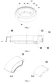
Fig. 1 is a schematic structural diagram of an electromagnet of a first embodiment of the present disclosure; -
Fig. 2 is a sectional view of an electromagnet of the first embodiment of the present disclosure; -
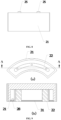
Figs. 3 (a) and 3 (b) are respectively schematic structural diagrams of a housing and an iron core of an electromagnet of a second embodiment of the present disclosure; -
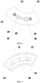
Fig. 4 is a schematic structural diagram of the electromagnet of the second embodiment of the present disclosure; -
Fig. 5 is another schematic structural diagram of the electromagnet of the second embodiment of the present disclosure; -
Fig. 6 is a top view of the electromagnet of the second embodiment of the present disclosure; -
Fig. 7 is another top view of the electromagnet of the second embodiment of the present disclosure; -
Fig. 8 is a side view of the electromagnet of the second embodiment of the present disclosure; -
Fig. 9 (b) is a sectional view of the plane A-A of the electromagnet ofFig. 9 (a) ; and -
Fig. 10 is a sectional view of the electromagnet of the second embodiment of the present disclosure when applied to an electromagnetic clutch. - The exemplary embodiments of the present disclosure will be described in further detail below by referring to the drawings. Although the drawings illustrate the exemplary embodiments of the present disclosure, it should be understood that, the present disclosure can be implemented in various forms, which should not be limited by the embodiments illustrated herein. In contrast, the purpose of providing those embodiments is to more clearly understand the present disclosure, and to completely convey the scope of the present disclosure to a person skilled in the art.
- As shown in
Figs. 1 and 2 jointly, the first embodiment of the present disclosure provides a split-type electromagnet, wherein the split-type electromagnet comprises ahousing 11 and aniron core 12, and a coil is wound around theiron core 12. Thehousing 11 and theiron core 12 are of a split type, wherein theiron core 12 is fixed within thehousing 11 after the coil has been wound around theiron core 12. Compared with the integrated type of thehousing 11 and theiron core 12 in the prior art, the winding of the coil is more convenient. - In the first embodiment of the present invention, the
housing 11 is a cylindrical body, theiron core 12 is a cylindrical body concentric with thehousing 11, the bottom end of theiron core 12 is provided with abottom board 13 that extends radially outwardly, and thebottom board 13 extends and covers the bottom end of thehousing 11. Certainly, thehousing 11 may also be configured as an ellipsoidal body, and theiron core 12 is correspondingly an ellipsoidal body concentric with the housing 11 (not shown in the drawings). In a preferable embodiment of the present disclosure, the thickness of the part of thebottom board 13 that covers the bottom end of thehousing 11 is less than that of the remaining part, and forms a clipping tab at the position, for positioning thebottom board 13 to the bottom end of thehousing 11. Certainly, that is merely one of split positioning modes, and other positioning modes may also be used according to the particular demand. The position of thebottom board 13 that covers the bottom end of thehousing 11 and the corresponding position of thehousing 11 are provided with a plurality of threaded holes, and after the coil has been wound around theiron core 12 theiron core 12 is fixed within thehousing 11 by using a plurality ofscrews 19. Certainly, other fixing modes may also be used, provided that the iron core can be fixed within the housing. - A side of the
housing 11 is provided with athreading hole 16 or a threading slot (not shown in the drawings), and aterminal 18 of the coil passes through thethreading hole 16 or threading slot. The threading slot refers to a notch provided at the open end of thehousing 11, wherein the terminal of the coil is pressed into the notch and fixed, and the terminal more easily threads out. The shape of thethreading hole 16 and threading slot may be configured according to the particular demand, provided that the terminal can thread out. - An inner wall of the
housing 11 and an outer wall of theiron core 12 are circumferentially provided withclipping grooves 17, and the positions of theclipping grooves 17 correspond to the top end of the coil. After theiron core 12 has been wound by the coil and fixed within thehousing 11, the top end of the coil is infused with a glue or a molten rubber, plastic or nylon, and the glue, rubber, plastic or nylon after being solidified engages with theclipping grooves 17 to fix the coil between thehousing 11 and theiron core 12, to prevent the coil from axially displacing along theiron core 12 when being electrified and generating a magnetic force. - In a preferable embodiment of the present disclosure, the end opening of the open end of the
housing 11 is provided with a blocking plate, which can also prevent the coil from axially displacing along theiron core 12 when being electrified and generating a magnetic force. - The bottom end of the
iron core 12 is provided with amounting base plate 14 that extends radially inwardly, or thebottom board 13 provided at the bottom end of theiron core 12 extends further to the periphery of thehousing 11 to form a mounting base plate (not shown in the drawings). Alternatively, a bottom end of the housing is provided with a mounting base plate that extends radially outwardly and a bottom board that extends radially inwardly, and the bottom board covers the bottom end of the iron core (not shown in the drawings). That is, the mounting base plate and the bottom board may be provided at the bottom end of the housing, and may also be provided at the bottom end of the iron core. - The mounting
base plate 14 is provided with a plurality of mountingholes 15, and the mountingholes 15 are unthreaded holes. When the electromagnet is being installed to other devices such as a clutch for use, the electromagnet is fixed at the usage position of the device by screwing screws into the mounting holes 15. Certainly, other fixing modes may also be used, provided that the electromagnet can be fixed to the device. - As shown in
Figs. 3 to 9 jointly, the second embodiment of the present invention provides a split-type electromagnet, wherein the split-type electromagnet comprises ahousing 21 and aniron core 22, and a coil 31 is wound around theiron core 22. Thehousing 21 and theiron core 22 are of a split type, wherein theiron core 22 is fixed within thehousing 21 after the coil has been wound around theiron core 22. - In the second embodiment of the present invention, the cross section of the
housing 21 is a sector-shaped ring. Alternatively, the edge of thehousing 21 is provided with a plurality of projections to increase the attracting area of the electromagnet, and the cross section of the housing is still generally a sector-shaped ring. The bottom end of thehousing 21 may be provided with abottom board 23, or, the bottom end of the iron core is provided with a bottom board and the bottom board covers the bottom end of the housing. That is, the bottom board may be provided at the bottom end of the housing, and may also be provided at the bottom end of the iron core. Theiron core 22 is an arc-shaped structure. Certainly, an alternative configuration is that the cross section of thehousing 21 is a rectangular ring, and theiron core 22 is correspondingly a rectangular structure (not shown in the drawings), or the cross sections of thehousing 21 and of theiron core 22 are approximately a rectangular ring; for example, the square edges of the rectangle are provided with chamfers. A connection of the bottom end of theiron core 22 and thebottom board 23 of thehousing 21 is provided with a plurality of threadedholes 29, and after the coil has been wound around theiron core 22 theiron core 22 is fixed within thehousing 21 by using a plurality ofscrews 30. Certainly, other fixing modes may also be used, provided that the iron core can be fixed within the housing. - A side of the
housing 21 is provided with athreading hole 28 or a threading slot (not shown in the drawings), and a terminal of the coil passes through thethreading hole 28 or threading slot. The threading slot refers to a notch provided at the open end of thehousing 21, wherein the terminal of the coil is pressed into the notch and fixed, and the terminal more easily threads out. The shape of thethreading hole 28 and threading slot may be configured according to the particular demand, provided that the terminal can thread out. - The
bottom board 23 of thehousing 21 is further provided with symmetrically two mounting positioning holes 24, and the mountingpositioning holes 24 are unthreaded holes. Matching positioning pins 25 are provided at the bottom of theiron core 22 at the positions that correspond to the mounting positioning holes 24, the positioning pins 25 are sleeve pins, and after theiron core 22 has been fixed within thehousing 21 the positioning pins 25 protrude out of the bottom of thehousing 21. On one hand, when theiron core 22 is being fixed within thehousing 21, the protruding positioning pins 25 facilitate positioning theiron core 22 to a desired position. On the other hand, when the electromagnet is being installed to other devices such as a clutch for use, counterbores that match the positioning pins 25 are provided at the positions corresponding to the device, the protruding positioning pins 25 facilitate positioning the electromagnet to a desired position of the device. Moreover, because the positioning pins 25 are sleeve pins, they can fix the electromagnet to the device. It should be noted that, here the positioning pins are used for the positioning, and certainly other positioning modes such as split positioning may also be used according to the particular demand. - A mounting
hole 26 is provided between the two mounting positioning holes 24, and the mountinghole 26 is an unthreaded hole. The corresponding position of the device is provided with a threaded hole, and a screw is screwed into the mountinghole 26 and the threaded hole, to further fix the electromagnet. Certainly, other fixing modes may also be used, provided that the electromagnet can be fixed to the device. - An inner wall of the
housing 21 and an outer wall of theiron core 22 are circumferentially provided with clippinggrooves 27, and the positions of the clippinggrooves 27 correspond to the top end of the coil. After theiron core 22 has been wound by the coil and fixed within thehousing 21, the top end of the coil is infused with a glue or a molten rubber, plastic or nylon, and the glue, rubber, plastic or nylon after being solidified engages with the clippinggrooves 27 to fix the coil between thehousing 21 and theiron core 22, to prevent the coil from axially displacing along theiron core 22 when being electrified and generating a magnetic force. - In a preferable embodiment of the present disclosure, the end opening of the open end of the
housing 21 is provided with a blocking plate, which can also prevent the coil from axially displacing along theiron core 22 when being electrified and generating a magnetic force. - A plurality of electromagnets in which the cross section of the
housing 21 is a sector-shaped ring combine to form an electromagnet unit. When the space is restricted, for example, as shown inFig. 10 , in an electromagnetic clutch, when an electromagnet is required to be provided around the meshing gear, symmetrically two aboveelectromagnets gears - In conclusion, the advantageous effects of the embodiments of the present disclosure are: the embodiments of the present disclosure provide a split-type electromagnet, wherein the split-type electromagnet comprises a housing and an iron core, wherein the housing and the iron core are of a split type, wherein the iron core is fixed within the housing after the coil has been wound around the iron core, and the housing is a cylindrical body or the cross section of the housing is a sector-shaped ring. Compared with the integrated type of the housing and the iron core in the prior art, the winding of the coil of the electromagnet is more convenient. Furthermore, when the cross section of the housing of the electromagnet is a sector-shaped ring, a plurality of electromagnets are combined to form an electromagnet unit, and when the space is restricted, the electromagnet unit may be used to complete the electromagnetic attraction.
- The above description is merely preferable embodiments of the present disclosure, and is not limiting the protection scope of the present disclosure. Any modifications, equivalent substitutions and improvements that are made within the principle of the present disclosure should fall within the protection scope of the present claims.
Claims (10)
- A split-type electromagnet, wherein the split-type electromagnet comprises a housing (11) and an iron core (12), and a coil is wound around the iron core (12), wherein the housing (11) and the iron core (12) are of a split type, the housing (11) is provided with a fixed position for the iron core (12) wound with coil, the housing (11) is a cylindrical body, the iron core (12) is a cylindrical body that is concentric with the housing (11), characterized in that an inner wall of the housing (11) and the outer wall of the iron core (12) are circumferentially provided with clipping grooves (17), and positions of the clipping grooves (17) correspond to a top end of the coil, and after the iron core has been wound by the coil and fixed within the housing, the top end of the coil is infused with a glue or a molten rubber, plastic or nylon, and the glue, rubber, plastic or nylon after being solidified engages with the clipping grooves to fix the coil between the housing and the iron core.
- A split-type electromagnet, wherein the split-type electromagnet comprises a housing (21) and an iron core (22), and a coil is wound around the iron core (22), wherein the housing (21) and the iron core (22) are of a split type, the housing (21) is provided with a fixed position for the iron core (22) wound with the coil, characterized in that a cross section of the housing (21) is a sector-shaped ring or a rectangular ring, the iron core (22) is an arc-shaped structure or a rectangular structure, an inner wall of the housing (21) and an outer wall of the iron core (22) are circumferentially provided with clipping grooves (27), and positions of the clipping grooves (27) correspond to a top end of the coil (31); and after the iron core has been wound by the coil and fixed within the housing, the top end of the coil is infused with a glue or a molten rubber, plastic or nylon, and the glue, rubber, plastic or nylon after being solidified engages with the clipping grooves to fix the coil (31) between the housing (21) and the iron core (22).
- The split-type electromagnet according to claim 1, characterized in that:a bottom end of the iron core (12) is provided with a bottom board (13) that extends radially outwardly, and the bottom board (13) covers a bottom end of the housing (11), and extends further to a periphery of the housing (11) to form a mounting base plate (14),or, a bottom end of the iron core (12) is provided with a mounting base plate (14) that extends radially inwardly;or, a bottom end of the housing (11) is provided with a mounting base plate (14) that extends radially outwardly and a bottom board (13) that extends radially inwardly, and the bottom board (13) covers a bottom end of the iron core (12);the clipping grooves (17) engages with a glue or a molten rubber, plastic or nylon to fix the coil between the housing (11) and the iron core (12).
- The split-type electromagnet according to claim 2, characterized in that: a bottom end of the housing (21) is provided with a bottom board (23), or, a bottom end of the iron core (22) is provided with a bottom board (23) and the bottom board (23) covers a bottom end of the housing (21).
- The split-type electromagnet according to claim 3, characterized in that: The mounting base plate (14) is provided with a plurality of mounting holes (15), and the mounting holes (15) are unthreaded holes.
- The split-type electromagnet according to claim 4, characterized in that: The bottom board (23) is further provided with symmetrically two mounting positioning holes (24), and the mounting positioning holes (24) are unthreaded holes;a mounting hole (26) is provided between the two mounting positioning holes (24), and the mounting hole (26) is an unthreaded hole; andmatching positioning pins (25) are provided at a bottom of the iron core (22) at positions that correspond to the mounting positioning holes (24), the positioning pins (25) are sleeve pins, and one end of the positioning pins (25) protrude out of a bottom of the housing (21).
- The split-type electromagnet according to claim 3, characterized in that: A side of the housing (11) is provided with a threading hole (16) or a threading slot, and the coil comprises a terminal that is configured to pass through the threading hole (16) or the threading slot.
- The split-type electromagnet according to claim 4, characterized in that: A side of the housing (21) is provided with a threading hole (28) or a threading slot, and the coil (31) comprise a terminal that is configured to pass through the threading hole (28) or the threading slot.
- The split-type electromagnet according to claim 3 or 4, characterized in that: An end opening of an open end of the housing (11, 21) is provided with a blocking plate, to prevent axial displacement of the coil along the iron core (12, 22).
- The split-type electromagnet according to claim 4, characterized in that: A plurality of electromagnets in which the cross section of the housing (21) is a sector-shaped ring or a rectangular ring combine to form an electromagnet unit.
Applications Claiming Priority (2)
| Application Number | Priority Date | Filing Date | Title |
|---|---|---|---|
| CN201620890204.1U CN206412163U (en) | 2016-08-16 | 2016-08-16 | A kind of Split type electric magnet |
| PCT/CN2017/071841 WO2018032726A1 (en) | 2016-08-16 | 2017-01-20 | Split-body electromagnet |
Publications (3)
| Publication Number | Publication Date |
|---|---|
| EP3480830A1 EP3480830A1 (en) | 2019-05-08 |
| EP3480830A4 EP3480830A4 (en) | 2019-09-18 |
| EP3480830B1 true EP3480830B1 (en) | 2025-04-09 |
Family
ID=59548659
Family Applications (1)
| Application Number | Title | Priority Date | Filing Date |
|---|---|---|---|
| EP17840704.5A Active EP3480830B1 (en) | 2016-08-16 | 2017-01-20 | Split-body electromagnet |
Country Status (5)
| Country | Link |
|---|---|
| US (1) | US11164691B2 (en) |
| EP (1) | EP3480830B1 (en) |
| JP (1) | JP6951419B2 (en) |
| CN (1) | CN206412163U (en) |
| WO (1) | WO2018032726A1 (en) |
Families Citing this family (1)
| Publication number | Priority date | Publication date | Assignee | Title |
|---|---|---|---|---|
| CN108978498A (en) * | 2018-07-04 | 2018-12-11 | 重庆三峡学院 | A kind of Bridge Rotation Construction Technique electromagnetism power-assisted component |
Citations (1)
| Publication number | Priority date | Publication date | Assignee | Title |
|---|---|---|---|---|
| CN203931707U (en) * | 2014-01-25 | 2014-11-05 | 诸暨市王杰电动门有限公司 | A kind of electromagnetic core shell |
Family Cites Families (34)
| Publication number | Priority date | Publication date | Assignee | Title |
|---|---|---|---|---|
| US3551864A (en) * | 1969-12-12 | 1970-12-29 | Pico Electronics Inc | Miniature inductive devices |
| CH528771A (en) | 1969-12-12 | 1972-05-31 | Bulova Watch Co Inc | Electronic watch |
| JPS4916153B1 (en) * | 1970-11-20 | 1974-04-19 | ||
| JPS4872662A (en) | 1971-12-29 | 1973-10-01 | ||
| BE795681A (en) | 1972-02-21 | 1973-08-20 | Philips Nv | MEASUREMENT CELL ALLOWING TO DETERMINE THE OXYGEN CONCENTRATION IN A GAS MIXTURE |
| JPS5149517Y2 (en) | 1972-02-24 | 1976-11-29 | ||
| JPS5043348A (en) | 1973-08-22 | 1975-04-19 | ||
| JPS5042157U (en) * | 1973-08-22 | 1975-04-28 | ||
| JPS52161250U (en) | 1976-05-28 | 1977-12-07 | ||
| JPS5511934Y2 (en) | 1976-10-06 | 1980-03-14 | ||
| JPS5383676U (en) | 1976-12-14 | 1978-07-11 | ||
| JPS5383676A (en) | 1976-12-28 | 1978-07-24 | Matsushita Electric Works Ltd | Ionization type smoke detector |
| JPS5485245U (en) * | 1977-11-30 | 1979-06-16 | ||
| JPS54101042A (en) | 1978-01-27 | 1979-08-09 | Hitachi Ltd | Electromagnetic clutch |
| JPS54155047U (en) * | 1978-04-19 | 1979-10-27 | ||
| JPS5813144Y2 (en) * | 1978-06-20 | 1983-03-14 | サンデン株式会社 | electromagnetic clutch |
| JPS5594039U (en) | 1978-12-23 | 1980-06-30 | ||
| JPS5718858U (en) * | 1980-07-02 | 1982-01-30 | ||
| JPS6256110A (en) | 1985-09-06 | 1987-03-11 | Mitsubishi Kasei Vinyl Co | Thermoplastic material supplying device for calender |
| JPH0220858Y2 (en) | 1985-11-06 | 1990-06-06 | ||
| DE8604637U1 (en) | 1986-02-21 | 1988-08-04 | K. Ernst Brinkmann Industrieverwaltung, 32683 Barntrup | Magnet for permanent magnet clutches, permanent magnet brakes or the like |
| JPS63162139U (en) * | 1987-04-13 | 1988-10-24 | ||
| JPH0544021Y2 (en) * | 1987-05-27 | 1993-11-08 | ||
| JPH01119176A (en) | 1987-10-31 | 1989-05-11 | Sharp Corp | Data transmission system |
| JPH01119176U (en) | 1988-02-08 | 1989-08-11 | ||
| JPH0626748Y2 (en) * | 1989-10-13 | 1994-07-20 | 小倉クラツチ株式会社 | Electromagnetic coupling device |
| JP2896445B2 (en) | 1990-07-09 | 1999-05-31 | カネテック株式会社 | Magnetic fixing device |
| JP3814776B2 (en) * | 1999-05-20 | 2006-08-30 | ミネベア株式会社 | Common mode choke coil |
| JP2007162748A (en) | 2005-12-09 | 2007-06-28 | Kyocera Mita Corp | Electromagnetic clutch |
| CN101615477B (en) | 2009-04-28 | 2011-04-06 | 浙江大学 | Biconical disc ratio electromagnet |
| CN101887794B (en) | 2009-05-15 | 2012-12-19 | 鸿富锦精密工业(深圳)有限公司 | Electromagnetic fixing device |
| CN202107845U (en) | 2011-04-20 | 2012-01-11 | 上海超诚电子科技有限公司 | Electromagnetic rod of high-velocity electronic dobby |
| WO2014024240A1 (en) | 2012-08-06 | 2014-02-13 | 日鍛バルブ株式会社 | Magnetic clutch attachment structure of engine variable phase device, magnetic clutch removal method, and magnetic clutch removal jig |
| CN204441020U (en) | 2014-12-24 | 2015-07-01 | 林建冰 | A kind of split type pore-free height conducting magnet core |
-
2016
- 2016-08-16 CN CN201620890204.1U patent/CN206412163U/en active Active
-
2017
- 2017-01-20 JP JP2019508218A patent/JP6951419B2/en active Active
- 2017-01-20 EP EP17840704.5A patent/EP3480830B1/en active Active
- 2017-01-20 WO PCT/CN2017/071841 patent/WO2018032726A1/en not_active Ceased
- 2017-01-20 US US16/322,385 patent/US11164691B2/en active Active
Patent Citations (1)
| Publication number | Priority date | Publication date | Assignee | Title |
|---|---|---|---|---|
| CN203931707U (en) * | 2014-01-25 | 2014-11-05 | 诸暨市王杰电动门有限公司 | A kind of electromagnetic core shell |
Also Published As
| Publication number | Publication date |
|---|---|
| US20190189324A1 (en) | 2019-06-20 |
| EP3480830A4 (en) | 2019-09-18 |
| EP3480830A1 (en) | 2019-05-08 |
| US11164691B2 (en) | 2021-11-02 |
| JP6951419B2 (en) | 2021-10-20 |
| JP2019532491A (en) | 2019-11-07 |
| WO2018032726A1 (en) | 2018-02-22 |
| CN206412163U (en) | 2017-08-15 |
Similar Documents
| Publication | Publication Date | Title |
|---|---|---|
| TWI451457B (en) | Primary side module and transformer using the same | |
| JP5874875B1 (en) | Core case unit, coil component, and method of manufacturing coil component | |
| JP6523626B2 (en) | Trance | |
| US2355477A (en) | Form for windings and the like | |
| KR20170003103A (en) | Insulator and Motor having the same | |
| JP3189670U (en) | Improved structure of transformer iron core | |
| CN109313979B (en) | Coil device | |
| US9350215B2 (en) | Method and structure for mounting sensor substrate of brushless motor | |
| CN104254223A (en) | Switch structure and electronic device with same | |
| JP2016054293A (en) | Filter component with windingless magnetic toroidal core | |
| US11164691B2 (en) | Split-body electromagnet | |
| JP6471489B2 (en) | Bobbin for coil component and method for manufacturing coil component | |
| US9076582B2 (en) | Magnetic component and bobbin thereof | |
| JP2014082266A (en) | Coil | |
| JP6283212B2 (en) | Winding parts | |
| JP5140737B2 (en) | Connection flange, especially for electrical connection terminals | |
| US20160055960A1 (en) | Power supply transformer | |
| JP2019175972A (en) | Solenoid of electromagnetic valve | |
| JP5400014B2 (en) | Self-holding solenoid | |
| KR102897229B1 (en) | Motor | |
| US8674801B2 (en) | Induction component | |
| JP5186607B1 (en) | Magnet holder, magnetic holding device using the same, and injection mold | |
| US20160233020A1 (en) | Transformer | |
| KR101503453B1 (en) | Transformer | |
| CN208737967U (en) | A kind of electromagnet |
Legal Events
| Date | Code | Title | Description |
|---|---|---|---|
| STAA | Information on the status of an ep patent application or granted ep patent |
Free format text: STATUS: THE INTERNATIONAL PUBLICATION HAS BEEN MADE |
|
| PUAI | Public reference made under article 153(3) epc to a published international application that has entered the european phase |
Free format text: ORIGINAL CODE: 0009012 |
|
| STAA | Information on the status of an ep patent application or granted ep patent |
Free format text: STATUS: REQUEST FOR EXAMINATION WAS MADE |
|
| 17P | Request for examination filed |
Effective date: 20190201 |
|
| AK | Designated contracting states |
Kind code of ref document: A1 Designated state(s): AL AT BE BG CH CY CZ DE DK EE ES FI FR GB GR HR HU IE IS IT LI LT LU LV MC MK MT NL NO PL PT RO RS SE SI SK SM TR |
|
| AX | Request for extension of the european patent |
Extension state: BA ME |
|
| STAA | Information on the status of an ep patent application or granted ep patent |
Free format text: STATUS: EXAMINATION IS IN PROGRESS |
|
| A4 | Supplementary search report drawn up and despatched |
Effective date: 20190816 |
|
| RIC1 | Information provided on ipc code assigned before grant |
Ipc: H01F 7/128 20060101ALI20190809BHEP Ipc: H01F 7/06 20060101AFI20190809BHEP |
|
| 17Q | First examination report despatched |
Effective date: 20190902 |
|
| DAV | Request for validation of the european patent (deleted) | ||
| DAX | Request for extension of the european patent (deleted) | ||
| GRAP | Despatch of communication of intention to grant a patent |
Free format text: ORIGINAL CODE: EPIDOSNIGR1 |
|
| STAA | Information on the status of an ep patent application or granted ep patent |
Free format text: STATUS: GRANT OF PATENT IS INTENDED |
|
| INTG | Intention to grant announced |
Effective date: 20241018 |
|
| GRAS | Grant fee paid |
Free format text: ORIGINAL CODE: EPIDOSNIGR3 |
|
| P01 | Opt-out of the competence of the unified patent court (upc) registered |
Free format text: CASE NUMBER: APP_62229/2024 Effective date: 20241121 |
|
| GRAA | (expected) grant |
Free format text: ORIGINAL CODE: 0009210 |
|
| STAA | Information on the status of an ep patent application or granted ep patent |
Free format text: STATUS: THE PATENT HAS BEEN GRANTED |
|
| AK | Designated contracting states |
Kind code of ref document: B1 Designated state(s): AL AT BE BG CH CY CZ DE DK EE ES FI FR GB GR HR HU IE IS IT LI LT LU LV MC MK MT NL NO PL PT RO RS SE SI SK SM TR |
|
| REG | Reference to a national code |
Ref country code: GB Ref legal event code: FG4D |
|
| REG | Reference to a national code |
Ref country code: CH Ref legal event code: EP |
|
| REG | Reference to a national code |
Ref country code: DE Ref legal event code: R096 Ref document number: 602017088852 Country of ref document: DE |
|
| REG | Reference to a national code |
Ref country code: IE Ref legal event code: FG4D |
|
| REG | Reference to a national code |
Ref country code: NL Ref legal event code: MP Effective date: 20250409 |
|
| PG25 | Lapsed in a contracting state [announced via postgrant information from national office to epo] |
Ref country code: NL Free format text: LAPSE BECAUSE OF FAILURE TO SUBMIT A TRANSLATION OF THE DESCRIPTION OR TO PAY THE FEE WITHIN THE PRESCRIBED TIME-LIMIT Effective date: 20250409 |
|
| REG | Reference to a national code |
Ref country code: AT Ref legal event code: MK05 Ref document number: 1784336 Country of ref document: AT Kind code of ref document: T Effective date: 20250409 |
|
| PG25 | Lapsed in a contracting state [announced via postgrant information from national office to epo] |
Ref country code: PT Free format text: LAPSE BECAUSE OF FAILURE TO SUBMIT A TRANSLATION OF THE DESCRIPTION OR TO PAY THE FEE WITHIN THE PRESCRIBED TIME-LIMIT Effective date: 20250811 Ref country code: ES Free format text: LAPSE BECAUSE OF FAILURE TO SUBMIT A TRANSLATION OF THE DESCRIPTION OR TO PAY THE FEE WITHIN THE PRESCRIBED TIME-LIMIT Effective date: 20250409 Ref country code: FI Free format text: LAPSE BECAUSE OF FAILURE TO SUBMIT A TRANSLATION OF THE DESCRIPTION OR TO PAY THE FEE WITHIN THE PRESCRIBED TIME-LIMIT Effective date: 20250409 |
|
| REG | Reference to a national code |
Ref country code: LT Ref legal event code: MG9D |
|
| PG25 | Lapsed in a contracting state [announced via postgrant information from national office to epo] |
Ref country code: NO Free format text: LAPSE BECAUSE OF FAILURE TO SUBMIT A TRANSLATION OF THE DESCRIPTION OR TO PAY THE FEE WITHIN THE PRESCRIBED TIME-LIMIT Effective date: 20250709 Ref country code: GR Free format text: LAPSE BECAUSE OF FAILURE TO SUBMIT A TRANSLATION OF THE DESCRIPTION OR TO PAY THE FEE WITHIN THE PRESCRIBED TIME-LIMIT Effective date: 20250710 |
|
| PG25 | Lapsed in a contracting state [announced via postgrant information from national office to epo] |
Ref country code: PL Free format text: LAPSE BECAUSE OF FAILURE TO SUBMIT A TRANSLATION OF THE DESCRIPTION OR TO PAY THE FEE WITHIN THE PRESCRIBED TIME-LIMIT Effective date: 20250409 |
|
| PG25 | Lapsed in a contracting state [announced via postgrant information from national office to epo] |
Ref country code: BG Free format text: LAPSE BECAUSE OF FAILURE TO SUBMIT A TRANSLATION OF THE DESCRIPTION OR TO PAY THE FEE WITHIN THE PRESCRIBED TIME-LIMIT Effective date: 20250409 |
|
| PG25 | Lapsed in a contracting state [announced via postgrant information from national office to epo] |
Ref country code: HR Free format text: LAPSE BECAUSE OF FAILURE TO SUBMIT A TRANSLATION OF THE DESCRIPTION OR TO PAY THE FEE WITHIN THE PRESCRIBED TIME-LIMIT Effective date: 20250409 |
|
| PG25 | Lapsed in a contracting state [announced via postgrant information from national office to epo] |
Ref country code: AT Free format text: LAPSE BECAUSE OF FAILURE TO SUBMIT A TRANSLATION OF THE DESCRIPTION OR TO PAY THE FEE WITHIN THE PRESCRIBED TIME-LIMIT Effective date: 20250409 |
|
| PG25 | Lapsed in a contracting state [announced via postgrant information from national office to epo] |
Ref country code: RS Free format text: LAPSE BECAUSE OF FAILURE TO SUBMIT A TRANSLATION OF THE DESCRIPTION OR TO PAY THE FEE WITHIN THE PRESCRIBED TIME-LIMIT Effective date: 20250709 |
|
| PG25 | Lapsed in a contracting state [announced via postgrant information from national office to epo] |
Ref country code: IS Free format text: LAPSE BECAUSE OF FAILURE TO SUBMIT A TRANSLATION OF THE DESCRIPTION OR TO PAY THE FEE WITHIN THE PRESCRIBED TIME-LIMIT Effective date: 20250809 |
|
| PG25 | Lapsed in a contracting state [announced via postgrant information from national office to epo] |
Ref country code: LV Free format text: LAPSE BECAUSE OF FAILURE TO SUBMIT A TRANSLATION OF THE DESCRIPTION OR TO PAY THE FEE WITHIN THE PRESCRIBED TIME-LIMIT Effective date: 20250409 |
|
| REG | Reference to a national code |
Ref country code: DE Ref legal event code: R097 Ref document number: 602017088852 Country of ref document: DE |
|
| PG25 | Lapsed in a contracting state [announced via postgrant information from national office to epo] |
Ref country code: SM Free format text: LAPSE BECAUSE OF FAILURE TO SUBMIT A TRANSLATION OF THE DESCRIPTION OR TO PAY THE FEE WITHIN THE PRESCRIBED TIME-LIMIT Effective date: 20250409 Ref country code: DK Free format text: LAPSE BECAUSE OF FAILURE TO SUBMIT A TRANSLATION OF THE DESCRIPTION OR TO PAY THE FEE WITHIN THE PRESCRIBED TIME-LIMIT Effective date: 20250409 |
|
| PG25 | Lapsed in a contracting state [announced via postgrant information from national office to epo] |
Ref country code: CZ Free format text: LAPSE BECAUSE OF FAILURE TO SUBMIT A TRANSLATION OF THE DESCRIPTION OR TO PAY THE FEE WITHIN THE PRESCRIBED TIME-LIMIT Effective date: 20250409 |
|
| PG25 | Lapsed in a contracting state [announced via postgrant information from national office to epo] |
Ref country code: EE Free format text: LAPSE BECAUSE OF FAILURE TO SUBMIT A TRANSLATION OF THE DESCRIPTION OR TO PAY THE FEE WITHIN THE PRESCRIBED TIME-LIMIT Effective date: 20250409 |
|
| PG25 | Lapsed in a contracting state [announced via postgrant information from national office to epo] |
Ref country code: SK Free format text: LAPSE BECAUSE OF FAILURE TO SUBMIT A TRANSLATION OF THE DESCRIPTION OR TO PAY THE FEE WITHIN THE PRESCRIBED TIME-LIMIT Effective date: 20250409 Ref country code: RO Free format text: LAPSE BECAUSE OF FAILURE TO SUBMIT A TRANSLATION OF THE DESCRIPTION OR TO PAY THE FEE WITHIN THE PRESCRIBED TIME-LIMIT Effective date: 20250409 |
|
| PG25 | Lapsed in a contracting state [announced via postgrant information from national office to epo] |
Ref country code: IT Free format text: LAPSE BECAUSE OF FAILURE TO SUBMIT A TRANSLATION OF THE DESCRIPTION OR TO PAY THE FEE WITHIN THE PRESCRIBED TIME-LIMIT Effective date: 20250409 |
|
| PLBE | No opposition filed within time limit |
Free format text: ORIGINAL CODE: 0009261 |
|
| STAA | Information on the status of an ep patent application or granted ep patent |
Free format text: STATUS: NO OPPOSITION FILED WITHIN TIME LIMIT |
|
| REG | Reference to a national code |
Ref country code: CH Ref legal event code: L10 Free format text: ST27 STATUS EVENT CODE: U-0-0-L10-L00 (AS PROVIDED BY THE NATIONAL OFFICE) Effective date: 20260218 |
|
| 26N | No opposition filed |
Effective date: 20260112 |
|
| PGFP | Annual fee paid to national office [announced via postgrant information from national office to epo] |
Ref country code: GB Payment date: 20260127 Year of fee payment: 10 |
|
| PGFP | Annual fee paid to national office [announced via postgrant information from national office to epo] |
Ref country code: DE Payment date: 20260114 Year of fee payment: 10 |
|
| PGFP | Annual fee paid to national office [announced via postgrant information from national office to epo] |
Ref country code: FR Payment date: 20260128 Year of fee payment: 10 |