EP3480681A1 - Haptic system with increased lra bandwidth - Google Patents
Haptic system with increased lra bandwidth Download PDFInfo
- Publication number
- EP3480681A1 EP3480681A1 EP18206808.0A EP18206808A EP3480681A1 EP 3480681 A1 EP3480681 A1 EP 3480681A1 EP 18206808 A EP18206808 A EP 18206808A EP 3480681 A1 EP3480681 A1 EP 3480681A1
- Authority
- EP
- European Patent Office
- Prior art keywords
- haptic effect
- frequency
- signal
- actuator
- resonant
- Prior art date
- Legal status (The legal status is an assumption and is not a legal conclusion. Google has not performed a legal analysis and makes no representation as to the accuracy of the status listed.)
- Withdrawn
Links
Images



Classifications
-
- H—ELECTRICITY
- H02—GENERATION; CONVERSION OR DISTRIBUTION OF ELECTRIC POWER
- H02N—ELECTRIC MACHINES NOT OTHERWISE PROVIDED FOR
- H02N2/00—Electric machines in general using piezoelectric effect, electrostriction or magnetostriction
- H02N2/02—Electric machines in general using piezoelectric effect, electrostriction or magnetostriction producing linear motion, e.g. actuators; Linear positioners ; Linear motors
- H02N2/06—Drive circuits; Control arrangements or methods
-
- G—PHYSICS
- G08—SIGNALLING
- G08B—SIGNALLING SYSTEMS, e.g. PERSONAL CALLING SYSTEMS; ORDER TELEGRAPHS; ALARM SYSTEMS
- G08B6/00—Tactile signalling systems, e.g. tactile personal calling systems
-
- G—PHYSICS
- G06—COMPUTING OR CALCULATING; COUNTING
- G06F—ELECTRIC DIGITAL DATA PROCESSING
- G06F3/00—Input arrangements for transferring data to be processed into a form capable of being handled by the computer; Output arrangements for transferring data from processing unit to output unit, e.g. interface arrangements
- G06F3/01—Input arrangements or combined input and output arrangements for interaction between user and computer
- G06F3/016—Input arrangements with force or tactile feedback as computer generated output to the user
-
- G—PHYSICS
- G06—COMPUTING OR CALCULATING; COUNTING
- G06F—ELECTRIC DIGITAL DATA PROCESSING
- G06F3/00—Input arrangements for transferring data to be processed into a form capable of being handled by the computer; Output arrangements for transferring data from processing unit to output unit, e.g. interface arrangements
- G06F3/01—Input arrangements or combined input and output arrangements for interaction between user and computer
- G06F3/048—Interaction techniques based on graphical user interfaces [GUI]
- G06F3/0487—Interaction techniques based on graphical user interfaces [GUI] using specific features provided by the input device, e.g. functions controlled by the rotation of a mouse with dual sensing arrangements, or of the nature of the input device, e.g. tap gestures based on pressure sensed by a digitiser
- G06F3/0488—Interaction techniques based on graphical user interfaces [GUI] using specific features provided by the input device, e.g. functions controlled by the rotation of a mouse with dual sensing arrangements, or of the nature of the input device, e.g. tap gestures based on pressure sensed by a digitiser using a touch-screen or digitiser, e.g. input of commands through traced gestures
Definitions
- One embodiment is directed generally to a system that generates haptic effects, and in particular to a system that generates haptic effects using a linear resonance actuator.
- Portable/mobile electronic devices such as mobile phones, smartphones, camera phones, cameras, personal digital assistants ("PDA"s), etc.
- PDA personal digital assistants
- a cell phone normally includes a speaker for audibly notifying the user of an incoming telephone call event.
- the audible signal may include specific ringtones, musical ditties, sound effects, etc.
- cell phones may include display screens that can be used to visually notify the users of incoming phone calls.
- kinesthetic feedback such as active and resistive force feedback
- tactile feedback such as vibration, texture, and heat
- Haptic feedback can provide cues that enhance and simplify the user interface.
- vibration effects, or vibrotactile haptic effects may be useful in providing cues to users of electronic devices to alert the user to specific events, or provide realistic feedback to create greater sensory immersion within a simulated or virtual environment.
- actuator/motor or haptic output device In order to generate vibration effects, many devices utilize some type of actuator/motor or haptic output device.
- actuators used for this purpose include a linear resonance actuator.
- One embodiment is a method of generating a haptic effect on a linear resonance actuator ("LRA") having a resonant frequency.
- the method includes receiving a haptic effect signal for the haptic effect, where the haptic effect comprises a desired frequency that is off-resonant from the LRA.
- the method further includes generating a first sine wave at the desired frequency and generating a second sine wave at or near the resonant frequency.
- the method further includes combining the first sine wave and the second sine wave to generate a drive signal.
- One embodiment is a system that generates haptic effects using a linear resonance actuator ("LRA").
- Embodiments combine multiple signals in order to drive the LRA at off-resonant frequencies to increase the bandwidth of the LRA.
- LRA may use a movable mass, permanent magnet, voice coil and spring to generate vibrations.
- the voice coil produces a magnetic field which interacts with the permanent magnet, causing it to move, which compresses or stretches the spring to which it is attached.
- the drive signal needs to alternate the direction of current (i.e., an alternating current ("AC") signal) and generate the magnetic field to make the permanent magnet oscillate back and forth with the spring.
- the moving mass is attached to the magnet, and the moving of the mass back and forth generates the vibrations.
- Another type of LRA may include two or more layers of piezo-electric ceramics with a mass attached so that when the piezo bends, the mass moves in a linear/oscillating fashion. Additional types of LRAs that include a vibrating motor that is driven with an oscillating signal can also be used with embodiments disclosed herein.
- AC drive signals can have a frequency and an amplitude. The higher the amplitude the greater the vibration output for a given frequency. However, the frequency of the drive signal can be an important factor.
- An LRA has a resonant frequency which the input signal should operate at, in order to maximize the vibration generated. Vibration performance drops off significantly when the input signal frequency is moved too far from the resonant frequency. Therefore, most haptic devices apply a drive signal at the resonant frequency of the LRA when generating haptic effects. Most LRAs used to generate haptic effects have a resonant frequency within the 150-200 Hz range.
- Fig. 1 is a block diagram of a haptically-enabled system 10 in accordance with one embodiment of the present invention.
- System 10 includes a touch sensitive surface 11 or other type of user interface mounted within a housing 15.
- System 10 further includes a pen/stylus 13 that is in communication with the rest of system 10 using a wireless (e.g., Bluetooth) or wired communication link.
- a wireless e.g., Bluetooth
- a haptic feedback system Internal to system 10 is a haptic feedback system that generates vibrations 30, 31 on stylus 13, as well as optionally on other areas of system 10, such as on touch surface 11 or housing 15.
- the haptic feedback system includes a processor or controller 12. Coupled to processor 12 is a memory 20 and an actuator drive circuit 16, which is coupled to an LRA 18.
- Processor 12 may be any type of general purpose processor, or could be a processor specifically designed to provide haptic effects, such as an application-specific integrated circuit ("ASIC").
- ASIC application-specific integrated circuit
- Processor 12 may be the same processor that operates the entire system 10, or may be a separate processor. Processor 12 can decide what haptic effects are to be played and the order in which the effects are played based in part on high level parameters.
- the high level parameters that define a particular haptic effect include magnitude, frequency and duration.
- Low level parameters such as streaming motor commands could also be used to determine a particular haptic effect.
- a haptic effect may be considered "dynamic" if it includes some variation of these parameters when the haptic effect is generated or a variation of these parameters based on a user's interaction.
- Processor 12 outputs the control signals to actuator drive circuit 16, which includes electronic components and circuitry used to supply LRA 18 with the required electrical current and voltage (i.e., "motor signals") to cause the desired haptic effects.
- System 10 may include more than one LRA 18, or other type of actuator, and each actuator may include a separate drive circuit 16, all coupled to a common processor 12.
- Memory device 20 can be any type of storage device or computer-readable medium, such as random access memory (“RAM”) or read-only memory (“ROM”).
- Memory 20 stores instructions executed by processor 12.
- memory 20 includes a haptic effects module 22 which are instructions that, when executed by processor 12, generate drive signals for LRA 18 that increase the output bandwidth of LRA 18, as disclosed in more detail below.
- Memory 20 may also be located internal to processor 12, or may be any combination of internal and external memory.
- Touch surface 11 recognizes touches, and may also recognize the position and magnitude of touches on the surface.
- the data corresponding to the touches is sent to processor 12, or another processor within system 10, and processor 12 interprets the touches and in response can generate haptic effect signals.
- Touch surface 11 may sense touches using any sensing technology, including capacitive sensing, resistive sensing, surface acoustic wave sensing, pressure sensing, optical sensing, etc.
- Touch surface 11 may sense multi-touch contacts and may be capable of distinguishing multiple touches that occur at the same time.
- Touch surface 11 may be a touchscreen that generates and displays images for the user to interact with, such as keys, dials, etc., or may be a touchpad with minimal or no images.
- System 10 may be a handheld device, such a cellular telephone, personal digital assistant ("PDA"), smartphone, computer tablet/pad, gaming console, etc., or may be any other type of device that includes a haptic effect system that includes one or more LRAs.
- System 10 may also be a wearable device (e.g., a bracelet, armband, glove, jacket, vest, pair of glasses, shoes, belt, etc.) that includes one or more LRAs that generate haptic effects.
- the user interface may be a touch sensitive surface, or can be any other type of user interface such as a mouse, touchpad, mini-joystick, scroll wheel, trackball, game pads or game controllers, etc.
- LRA 18 and drive circuit 16 are located within stylus 13, and generate haptic effects directly on stylus 13.
- the remaining elements of the haptic effect system are located within housing 15, and are in communication with stylus 13.
- system 10 requires LRA 18 to have a wider frequency response range than standard LRAs because it has a need to generate a wide variety of haptic effects to be designed off-resonance.
- one embodiment generates haptic effects on stylus 13 to simulate a texture when used by a user to "draw" on screen 11.
- haptic effects by LRA 18 can cause stylus 13 to simulate a pen or pencil using different off-resonance haptic signals (i.e., stylus 13 can feel to a user like a pencil or a pen, depending on which haptic effect is generated by LRA 18). These types of haptic effects may further require the independent variation of the frequency and strength of the vibration.
- Known haptic effect systems e.g., the "Touchsense 3000" from Immersion Corp.
- LRA liquid crystal display
- PWM pulse-width modulation
- AC drive signal whose frequency generally corresponds to the actuator's resonant frequency (typically 175 Hz).
- one embodiment allows for the independent control of frequency and strength on the LRA to increase the bandwidth of the LRA.
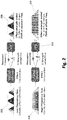
- Fig. 2 illustrates the handling of the frequency parameter of a haptic effect in accordance with one embodiment of the present invention.
- the haptic effect is ultimately rendered or played by a "TS5000 Player" from Immersion Corp. and will be interpreted in different ways based on its frequency characteristics.
- the frequency and wave shape will be interpreted as an envelope.
- the effect is a sine wave
- the strength of the effect will rise and fall following the shape of the sine wave.
- the output effect 208 will be at the resonant frequency of the LRA and will be modulated by the input effect 202.
- this pulsing effect can only be done if the designed frequency is around 20Hz or lower in one embodiment. The exact frequency for this pulsing range depends on the LRA's resonant frequency and the rise time (or the time it takes the actuator to reach nominal acceleration).
- SPI 213 In one embodiment, is responsible for sending the frequency and strength values to stylus 13 (over Bluetooth or other medium), and scales the effect strength to match the envelope. This technique is effective for a range of frequencies near the resonance frequency of the LRA (e.g., approximately 150-250 Hz).
- embodiments transition between the above modes.
- the frequency range depends upon the actuator used and could be lower than a typical or common medium frequency range for an LRA.
- the lower end of the middle range could be less than or equal to 2 Hz and a high end of the middle range could be equal to or greater than 200 Hz.
- Embodiments implement one or more of the below techniques for transitioning between the high and low frequency in order to generated increased LRA bandwidth haptic effects.
- a single point in the critical range i.e., "mid-range” frequencies, for example, 20-150Hz
- Any desired frequency below that point is rendered by enveloping a signal at resonant frequency with a sine wave at the desired frequency.
- Any desired frequency above this point is used to directly drive the actuator.
- the transition from one drive mode to the other may be abrupt and the strength of the vibration may be very weak near the transition point. The greater the disparity between the wavelength of the signal at resonance and rise time plus fall time, the less effective the single transition point becomes.
- the transition point may be determined algorithmically by measuring acceleration using an accelerometer mounted to the device, such as being mounted on LRA 18.
- the drive signal for the test is made up of a sine or square wave at the device's resonant frequency multiplied by a sine wave that varies in frequency from low to high (frequency sweep), spanning the critical range.
- the acceleration will rise and fall with the envelope wave and the peak acceleration during each period decreases as the envelope frequency increases.
- a sine wave frequency sweep (without the resonant component) is played, generating a second acceleration trace that generally increases in strength as the frequency increases until it reaches the resonant frequency of the device.
- the best transition point for optimizing strength is where the graphs of these two accelerometer traces cross.
- the transition point may be determined manually by a user feeling these two frequency sweeps. It may be desirable to have a lower or higher transition point based on personal preference or other factors.
- the transition point can be a design-time decision, so that the haptic effect designer (using, e.g., the "Haptic Studio” from Immersion Corp.) may choose which mode to use for the effect.
- the haptic effect designer using, e.g., the "Haptic Studio” from Immersion Corp.
- Embodiments may implement this decision by providing an additional parameter to the definition of the effect, expanding existing parameters to include additional discrete values, or repurposing or redefining existing parameters.
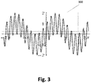
- FIG. 3 illustrates a complex waveform 300 using a carrier wave in accordance with one embodiment.
- Waveform 300 of Fig. 3 is the sum of two sine waves, although the higher frequency wave can also be a square wave.
- One embodiment determines f resonant by multiplying the desired frequency f desired by an integer so that the result is as close as possible to the true resonant frequency. For example, if the actual resonant frequency is 175Hz and the desired is 55Hz, a factor of 3 will result in a 165Hz value for f resonant . A factor of 4 would result in a 220Hz value. 165 Hz is closer to the true resonant frequency, so that is what would be used.
- a and B are scaled inversely over the transitional range such that the enveloped resonant signal is dominant at the low end of the range, and the direct-drive signal is dominant near the high end of the range.
- V desired is the desired driving voltage of the actuator
- f resonant is a multiple of f desired that is as close as possible to the true resonant frequency of the actuator in order to avoid phasing waveforms.
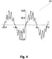
- Fig. 4 illustrates a complex waveform 400 using a scaled product in accordance with a embodiment.
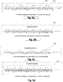
- Figs. 5a-5d illustrate various waveforms of the scaled product in accordance with one embodiment.
- Fig. 5a illustrates a resonant frequency waveform 501 and a slow enveloped waveform 502 to which it will be multiplied by in accordance with one embodiment.
- Fig. 5b illustrates a scaled envelope waveform 503 of Fig. 5a in accordance with one embodiment.
- Fig. 5c illustrates a scaled direct drive waveform 504 in accordance with one embodiment.
- Fig. 5d illustrates a scaled composite waveform 505 formed from the scaled envelope waveform 503 of Fig. 5b added to the scaled direct drive waveform 504 of Fig. 5c in accordance with one embodiment.
- some embodiments boost the off-resonance drive signals to achieve a flatter response curve (i.e., the graph of acceleration measured by accelerometer vs. drive frequency).
- Embodiments can boost the signal using one or more of the following, in addition to other known methods:
- Fig. 6 is a flow diagram of the functionality of system 10 of Fig. 1 when generating haptic effects using an LRA in accordance with one embodiment.
- the functionality of the flow diagram of Fig. 6 is implemented by software stored in memory or other computer readable or tangible medium, and executed by a processor.
- the functionality may be performed by hardware (e.g., through the use of an application specific integrated circuit ("ASIC"), a programmable gate array (“PGA”), a field programmable gate array (“FPGA”), etc.), or any combination of hardware and software.
- ASIC application specific integrated circuit
- PGA programmable gate array
- FPGA field programmable gate array
- the haptic effect signal is received.
- the haptic effect signal has a frequency (i.e., the desired frequency or " f desired ”) that is an off-resonant frequency of the LRA (i.e., not at the LRA's resonant frequency) that will generate the haptic effect.
- a sine wave at or near the resonant frequency of the LRA is generated.
- the sine wave frequency is the frequency that is an integer multiple of the off-resonant frequency but is as close to the resonant frequency as possible (" f resonant ").
- the sine waves from 604 and 606 are combined and multiplied by the maximum rated driving voltage of the LRA to generate the resultant haptic effect signal.
- the calculations are between 0 and 1, so this resulting scalar would be multiplied by the maximum drive voltage the LRA can handle.
- the calculations use integer math in the range of -127..127 rather than floating point from 0..1.
- embodiments generate haptic effects that include an off-resonant frequency component.
- the bandwidth of the LRA that generates the haptic effect is expanded so that it can render the haptic effects.
- Fig. 7 illustrates an example graph 702 of an LRA generating haptic effects primarily at resonant frequency, and a graph 704 of an LRA generating haptic effects with an increased range/bandwidth in accordance with embodiments of the present invention.
Landscapes
- Engineering & Computer Science (AREA)
- General Engineering & Computer Science (AREA)
- Theoretical Computer Science (AREA)
- Physics & Mathematics (AREA)
- General Physics & Mathematics (AREA)
- Human Computer Interaction (AREA)
- User Interface Of Digital Computer (AREA)
- Apparatuses For Generation Of Mechanical Vibrations (AREA)
Abstract
Description
- This application claims priority of
U.S. Provisional Patent Application Serial No. 61/736,912, filed on December 13, 2012 U.S. Provisional Patent Application Serial No. 61/790,190, filed on March 15, 2013 - One embodiment is directed generally to a system that generates haptic effects, and in particular to a system that generates haptic effects using a linear resonance actuator.
- Portable/mobile electronic devices, such as mobile phones, smartphones, camera phones, cameras, personal digital assistants ("PDA"s), etc., typically include output mechanisms to alert the user of certain events that occur with respect to the devices. For example, a cell phone normally includes a speaker for audibly notifying the user of an incoming telephone call event. The audible signal may include specific ringtones, musical ditties, sound effects, etc. In addition, cell phones may include display screens that can be used to visually notify the users of incoming phone calls.
- In some mobile devices, kinesthetic feedback (such as active and resistive force feedback) and/or tactile feedback (such as vibration, texture, and heat) is also provided to the user, more generally known collectively as "haptic feedback" or "haptic effects". Haptic feedback can provide cues that enhance and simplify the user interface. Specifically, vibration effects, or vibrotactile haptic effects, may be useful in providing cues to users of electronic devices to alert the user to specific events, or provide realistic feedback to create greater sensory immersion within a simulated or virtual environment. In order to generate vibration effects, many devices utilize some type of actuator/motor or haptic output device. Known actuators used for this purpose include a linear resonance actuator.
- One embodiment is a method of generating a haptic effect on a linear resonance actuator ("LRA") having a resonant frequency. The method includes receiving a haptic effect signal for the haptic effect, where the haptic effect comprises a desired frequency that is off-resonant from the LRA. The method further includes generating a first sine wave at the desired frequency and generating a second sine wave at or near the resonant frequency. The method further includes combining the first sine wave and the second sine wave to generate a drive signal.
-
-
Fig. 1 is a block diagram of a haptically-enabled system in accordance with one embodiment of the present invention. -
Fig. 2 illustrates the handling of the frequency parameter of a haptic effect in accordance with one embodiment of the present invention. -
Fig. 3 illustrates a complex waveform using a carrier wave in accordance with one embodiment. -
Fig. 4 illustrates a complex waveform using a scaled product in accordance with one embodiment. -
Figs. 5a-5d illustrate various waveforms of the scaled product in accordance with one embodiment. -
Fig. 6 is a flow diagram of the functionality of the system ofFig. 1 when generating haptic effects using an LRA in accordance with one embodiment. -
Fig. 7 illustrates an example graph of an LRA generating haptic effects primarily at resonant frequency, and a graph of an LRA generating haptic effects with an increased range/bandwidth in accordance with embodiments of the present invention. - One embodiment is a system that generates haptic effects using a linear resonance actuator ("LRA"). Embodiments combine multiple signals in order to drive the LRA at off-resonant frequencies to increase the bandwidth of the LRA.
- One type of LRA may use a movable mass, permanent magnet, voice coil and spring to generate vibrations. The voice coil produces a magnetic field which interacts with the permanent magnet, causing it to move, which compresses or stretches the spring to which it is attached. The drive signal needs to alternate the direction of current (i.e., an alternating current ("AC") signal) and generate the magnetic field to make the permanent magnet oscillate back and forth with the spring. The moving mass is attached to the magnet, and the moving of the mass back and forth generates the vibrations. Another type of LRA may include two or more layers of piezo-electric ceramics with a mass attached so that when the piezo bends, the mass moves in a linear/oscillating fashion. Additional types of LRAs that include a vibrating motor that is driven with an oscillating signal can also be used with embodiments disclosed herein.
- AC drive signals can have a frequency and an amplitude. The higher the amplitude the greater the vibration output for a given frequency. However, the frequency of the drive signal can be an important factor. An LRA has a resonant frequency which the input signal should operate at, in order to maximize the vibration generated. Vibration performance drops off significantly when the input signal frequency is moved too far from the resonant frequency. Therefore, most haptic devices apply a drive signal at the resonant frequency of the LRA when generating haptic effects. Most LRAs used to generate haptic effects have a resonant frequency within the 150-200 Hz range.
- In contrast with known haptic systems that use LRAs, the type of haptic effects generated by embodiments of the present invention require an increased range/bandwidth of an LRA, outside of its resonant frequency, to be effective. Specifically,
Fig. 1 is a block diagram of a haptically-enabledsystem 10 in accordance with one embodiment of the present invention.System 10 includes a touchsensitive surface 11 or other type of user interface mounted within ahousing 15.System 10 further includes a pen/stylus 13 that is in communication with the rest ofsystem 10 using a wireless (e.g., Bluetooth) or wired communication link. - Internal to
system 10 is a haptic feedback system that generatesvibrations stylus 13, as well as optionally on other areas ofsystem 10, such as ontouch surface 11 orhousing 15. The haptic feedback system includes a processor orcontroller 12. Coupled toprocessor 12 is amemory 20 and anactuator drive circuit 16, which is coupled to anLRA 18.Processor 12 may be any type of general purpose processor, or could be a processor specifically designed to provide haptic effects, such as an application-specific integrated circuit ("ASIC").Processor 12 may be the same processor that operates theentire system 10, or may be a separate processor.Processor 12 can decide what haptic effects are to be played and the order in which the effects are played based in part on high level parameters. In general, the high level parameters that define a particular haptic effect include magnitude, frequency and duration. Low level parameters such as streaming motor commands could also be used to determine a particular haptic effect. A haptic effect may be considered "dynamic" if it includes some variation of these parameters when the haptic effect is generated or a variation of these parameters based on a user's interaction. -
Processor 12 outputs the control signals toactuator drive circuit 16, which includes electronic components and circuitry used to supplyLRA 18 with the required electrical current and voltage (i.e., "motor signals") to cause the desired haptic effects.System 10 may include more than one LRA 18, or other type of actuator, and each actuator may include aseparate drive circuit 16, all coupled to acommon processor 12. -
Memory device 20 can be any type of storage device or computer-readable medium, such as random access memory ("RAM") or read-only memory ("ROM").Memory 20 stores instructions executed byprocessor 12. Among the instructions,memory 20 includes ahaptic effects module 22 which are instructions that, when executed byprocessor 12, generate drive signals for LRA 18 that increase the output bandwidth of LRA 18, as disclosed in more detail below.Memory 20 may also be located internal toprocessor 12, or may be any combination of internal and external memory. -
Touch surface 11 recognizes touches, and may also recognize the position and magnitude of touches on the surface. The data corresponding to the touches is sent toprocessor 12, or another processor withinsystem 10, andprocessor 12 interprets the touches and in response can generate haptic effect signals.Touch surface 11 may sense touches using any sensing technology, including capacitive sensing, resistive sensing, surface acoustic wave sensing, pressure sensing, optical sensing, etc.Touch surface 11 may sense multi-touch contacts and may be capable of distinguishing multiple touches that occur at the same time.Touch surface 11 may be a touchscreen that generates and displays images for the user to interact with, such as keys, dials, etc., or may be a touchpad with minimal or no images. -
System 10 may be a handheld device, such a cellular telephone, personal digital assistant ("PDA"), smartphone, computer tablet/pad, gaming console, etc., or may be any other type of device that includes a haptic effect system that includes one or more LRAs.System 10 may also be a wearable device (e.g., a bracelet, armband, glove, jacket, vest, pair of glasses, shoes, belt, etc.) that includes one or more LRAs that generate haptic effects. The user interface may be a touch sensitive surface, or can be any other type of user interface such as a mouse, touchpad, mini-joystick, scroll wheel, trackball, game pads or game controllers, etc. - In one embodiment,
LRA 18 and drivecircuit 16 are located withinstylus 13, and generate haptic effects directly onstylus 13. In this embodiment, the remaining elements of the haptic effect system are located withinhousing 15, and are in communication withstylus 13. As discussed above,system 10 requiresLRA 18 to have a wider frequency response range than standard LRAs because it has a need to generate a wide variety of haptic effects to be designed off-resonance. For example, one embodiment generates haptic effects onstylus 13 to simulate a texture when used by a user to "draw" onscreen 11. Further generated haptic effects byLRA 18 can causestylus 13 to simulate a pen or pencil using different off-resonance haptic signals (i.e.,stylus 13 can feel to a user like a pencil or a pen, depending on which haptic effect is generated by LRA 18). These types of haptic effects may further require the independent variation of the frequency and strength of the vibration. - Known haptic effect systems (e.g., the "Touchsense 3000" from Immersion Corp.) that use an LRA typically use a controller to communicate the haptic drive signal using a pulse-width modulation ("PWM") signal (i.e., a rectangular pulse wave whose pulse width is modulated). These known systems require an AC drive signal whose frequency generally corresponds to the actuator's resonant frequency (typically 175 Hz). In contrast, one embodiment allows for the independent control of frequency and strength on the LRA to increase the bandwidth of the LRA.
-
Fig. 2 illustrates the handling of the frequency parameter of a haptic effect in accordance with one embodiment of the present invention. In the example ofFig. 2 , the haptic effect is ultimately rendered or played by a "TS5000 Player" from Immersion Corp. and will be interpreted in different ways based on its frequency characteristics. - Specifically, for low frequencies (e.g., less than 20 Hz) such as
input effect 202, the frequency and wave shape will be interpreted as an envelope. For example, if the effect is a sine wave, the strength of the effect will rise and fall following the shape of the sine wave. Theoutput effect 208 will be at the resonant frequency of the LRA and will be modulated by theinput effect 202. Depending on actuator capabilities, this pulsing effect can only be done if the designed frequency is around 20Hz or lower in one embodiment. The exact frequency for this pulsing range depends on the LRA's resonant frequency and the rise time (or the time it takes the actuator to reach nominal acceleration). - For high frequencies (e.g., greater than 150 Hz) such as
input effect 210, the frequency parameter will be passed through to a Service Provider Interface ("SPI") 213 or other interface unit.SPI 213 in one embodiment is responsible for sending the frequency and strength values to stylus 13 (over Bluetooth or other medium), and scales the effect strength to match the envelope. This technique is effective for a range of frequencies near the resonance frequency of the LRA (e.g., approximately 150-250 Hz). - In contrast to the "low" and "high" frequency haptic effects described above, for "mid-range" frequency haptic effects (e.g., 20-150Hz), embodiments transition between the above modes. The frequency range depends upon the actuator used and could be lower than a typical or common medium frequency range for an LRA. For example, the lower end of the middle range could be less than or equal to 2 Hz and a high end of the middle range could be equal to or greater than 200 Hz. Embodiments implement one or more of the below techniques for transitioning between the high and low frequency in order to generated increased LRA bandwidth haptic effects.
- In one embodiment, a single point in the critical range (i.e., "mid-range" frequencies, for example, 20-150Hz) is selected. Any desired frequency below that point is rendered by enveloping a signal at resonant frequency with a sine wave at the desired frequency. Any desired frequency above this point is used to directly drive the actuator. However, the transition from one drive mode to the other may be abrupt and the strength of the vibration may be very weak near the transition point. The greater the disparity between the wavelength of the signal at resonance and rise time plus fall time, the less effective the single transition point becomes.
- The transition point may be determined algorithmically by measuring acceleration using an accelerometer mounted to the device, such as being mounted on
LRA 18. The drive signal for the test is made up of a sine or square wave at the device's resonant frequency multiplied by a sine wave that varies in frequency from low to high (frequency sweep), spanning the critical range. The acceleration will rise and fall with the envelope wave and the peak acceleration during each period decreases as the envelope frequency increases. Additionally, a sine wave frequency sweep (without the resonant component) is played, generating a second acceleration trace that generally increases in strength as the frequency increases until it reaches the resonant frequency of the device. The best transition point for optimizing strength is where the graphs of these two accelerometer traces cross. - In another embodiment, the transition point may be determined manually by a user feeling these two frequency sweeps. It may be desirable to have a lower or higher transition point based on personal preference or other factors.
- In another embodiments, the transition point can be a design-time decision, so that the haptic effect designer (using, e.g., the "Haptic Studio" from Immersion Corp.) may choose which mode to use for the effect. Embodiments may implement this decision by providing an additional parameter to the definition of the effect, expanding existing parameters to include additional discrete values, or repurposing or redefining existing parameters.
- Another embodiment uses the desired frequency of the haptic effect as a carrier wave added to the resonant frequency. In order to increase the useable frequency range while maintaining the strength in the transitional region, two complex waveforms may be used.
Fig. 3 illustrates acomplex waveform 300 using a carrier wave in accordance with one embodiment.Waveform 300 ofFig. 3 is the sum of two sine waves, although the higher frequency wave can also be a square wave.Waveform 300 is defined as follows:
- In another embodiment, to smoothly transition between sine-enveloped pulsing and direct-drive modes, the enveloped signal can be added to a sine wave at or near resonance to produce a composite of both drive signals as follows:

Fig. 4 illustrates acomplex waveform 400 using a scaled product in accordance with a embodiment. -
Figs. 5a-5d illustrate various waveforms of the scaled product in accordance with one embodiment.Fig. 5a illustrates aresonant frequency waveform 501 and a slow envelopedwaveform 502 to which it will be multiplied by in accordance with one embodiment.Fig. 5b illustrates a scaledenvelope waveform 503 ofFig. 5a in accordance with one embodiment.Fig. 5c illustrates a scaleddirect drive waveform 504 in accordance with one embodiment.Fig. 5d illustrates a scaledcomposite waveform 505 formed from the scaledenvelope waveform 503 ofFig. 5b added to the scaleddirect drive waveform 504 ofFig. 5c in accordance with one embodiment. - In all embodiments described above, driving an LRA off-resonance will result in a reduction of strength in the haptic effect. Therefore, some embodiments boost the off-resonance drive signals to achieve a flatter response curve (i.e., the graph of acceleration measured by accelerometer vs. drive frequency). Embodiments can boost the signal using one or more of the following, in addition to other known methods:
- 1. Applying a gain to each sine wave that contributes to the signal independently;
- 2. Multiplying the computed composite wave by a scale factor based on the frequencies present; and
- 3. Multiplying the computed composite wave by a predefined scale factor and applying one or more filters (e.g., notch, high-pass, low-pass, etc.) to attenuate the strength at the resonant frequency.
-
Fig. 6 is a flow diagram of the functionality ofsystem 10 ofFig. 1 when generating haptic effects using an LRA in accordance with one embodiment. In one embodiment, the functionality of the flow diagram ofFig. 6 is implemented by software stored in memory or other computer readable or tangible medium, and executed by a processor. In other embodiments, the functionality may be performed by hardware (e.g., through the use of an application specific integrated circuit ("ASIC"), a programmable gate array ("PGA"), a field programmable gate array ("FPGA"), etc.), or any combination of hardware and software. - At 602, the haptic effect signal is received. The haptic effect signal has a frequency (i.e., the desired frequency or "fdesired ") that is an off-resonant frequency of the LRA (i.e., not at the LRA's resonant frequency) that will generate the haptic effect.
- At 604, a sine wave at the desired frequency is generated.
- At 606, a sine wave at or near the resonant frequency of the LRA is generated. In one embodiment, the sine wave frequency is the frequency that is an integer multiple of the off-resonant frequency but is as close to the resonant frequency as possible ("fresonant ").
- At 608, the sine waves from 604 and 606 are combined and multiplied by the maximum rated driving voltage of the LRA to generate the resultant haptic effect signal. In one embodiment, the sine waves are combined as follows:

- In another embodiment., the sine waves are combined as follows:

- The calculations are between 0 and 1, so this resulting scalar would be multiplied by the maximum drive voltage the LRA can handle. In one embodiment, the calculations use integer math in the range of -127..127 rather than floating point from 0..1.
- As disclosed, embodiments generate haptic effects that include an off-resonant frequency component. In generating the haptic effect, the bandwidth of the LRA that generates the haptic effect is expanded so that it can render the haptic effects.
Fig. 7 illustrates anexample graph 702 of an LRA generating haptic effects primarily at resonant frequency, and agraph 704 of an LRA generating haptic effects with an increased range/bandwidth in accordance with embodiments of the present invention. - The present invention is further directed to embodiments according to the following items:
- Item 1: A method of generating a haptic effect on a linear resonance actuator (LRA) having a resonant frequency, the method comprising:
- receiving a haptic effect signal for the haptic effect, wherein the haptic effect comprises a desired frequency that is off-resonant from the LRA;
- generating a first sine wave at the desired frequency;
- generating a second sine wave at or near the resonant frequency; and
- combining the first sine wave and the second sine wave to generate a drive signal.
- Item 2: The method of
item 1, wherein combining the first sine wave and the second sine wave comprises:
- Item 3: The method of
item 1, wherein combining the first sine wave and the second sine wave comprises:
- Item 4. The method of
item 1, wherein generating the second sine wave at or near the resonant frequency comprises determining a sine wave frequency that is an integer multiple of the off-resonant frequency and is as close to the resonant frequency as possible. - Item 5. The method of
item 1, further comprising multiplying the combined first sine wave and second sine wave by a desired driving voltage. - Item 6. The method of
item 1, further comprising boosting the drive signal. - Item 7. The method of
item 1, wherein the LRA comprises a moving mass. - Item 8. The method of
item 1, wherein the LRA is coupled to a stylus. - Item 9. A computer-readable medium having instructions stored thereon that, when executed by a processor, cause the processor to generate a haptic effect on a linear resonance actuator (LRA) having a resonant frequency, the generating comprising at least one or more of the methods of items 1-8.
-
Item 10. A haptic effect system comprising:- a linear resonance actuator (LRA) having a resonant frequency;
- an actuator drive circuit coupled to the LRA;
- a controller coupled to the actuator drive circuit, wherein the controller receives a haptic effect signal for a haptic effect, wherein the haptic effect comprises a desired frequency that is off-resonant from the LRA;
- the controller adapted to execute one or more of the methods of items 1-8.
-
Item 11. The haptic effect system ofitem 10, wherein the LRA and the actuator drive circuit are coupled to a stylus and wirelessly coupled to the controller. - Several embodiments are specifically illustrated and/or described herein. However, it will be appreciated that modifications and variations of the disclosed embodiments are covered by the above teachings and within the purview of the appended claims without departing from the spirit and intended scope of the invention. For example, although some embodiments use an LRA, any system with an actuator device that experiences a sharp fall-off in performance at off-resonance frequencies when generating haptic effects can use embodiments of the present invention.
Claims (15)
- A method for generating a haptic effect on a linear resonance actuator having a resonant frequency, the method comprising:receiving an input haptic effect signal comprising a desired input frequency that is off-resonant from the linear resonance actuator;determining whether the desired input frequency is below or above a transition point frequency;when the desired input frequency is below the transition point frequency, generating a first output haptic effect signal by enveloping a signal at the resonant frequency with a sine wave at the desired input frequency; andapplying the first output haptic effect signal to the linear resonance actuator to generate the haptic effect.
- The method of claim 1, further comprising:when the desired input frequency is above the transition point frequency, using the input haptic effect signal as a second output haptic effect signal;applying the second output haptic effect signal to the linear resonance actuator to generate the haptic effect.
- The method of claim 1, further comprising:determining the transition point frequency using an input signal generated by an accelerometer mounted on the linear resonance actuator or mounted on a device housing the linear resonance actuator.
- The method of claim 1, wherein the first output haptic effect signal comprises a pulse-width modulation signal at the resonant frequency.
- The method of claim 2, wherein the second output haptic effect signal comprises a pulse-width modulation signal at the desired input frequency.
- The method of claim 5, wherein the second output haptic effect signal is scaled to match an envelope.
- The method of claim 1, wherein when the desired input frequency is below the transition point frequency, the desired input frequency is an off-resonance frequency.
- The method of claim 1, wherein the first output haptic effect signal comprises off-resonance drive signals, further comprising boosting the off-resonance drive signals before applying.
- A haptic effect system comprising:a linear resonance actuator having a resonant frequency;an actuator drive circuit coupled to the linear resonance actuator;a controller coupled to the actuator drive circuit, wherein the controller receives an input haptic effect signal comprising a desired input frequency that is off-resonant from the linear resonance actuator;the controller adapted to determine whether the desired input frequency is below or above a transition point frequency, and when the desired input frequency is below the transition point frequency, generate a first output haptic effect signal by enveloping a signal at the resonant frequency with a sine wave at the desired input frequency, and transmit the first output haptic effect signal to the actuator drive circuit;the actuator drive circuit applies the first output haptic effect signal to the linear resonance actuator, causing the linear resonance actuator to generate a haptic effect.
- The haptic effect system of claim 9, the controller further adapted to, when the desired input frequency is above the transition point frequency, use the input haptic effect signal as a second output haptic effect signal;
the actuator drive circuit applying the second output haptic effect signal to the linear resonance actuator to generate the haptic effect. - The haptic effect system of claim 9, further comprising:an accelerometer mounted on the linear resonance actuator or mounted on a housing of the system;the controller further adapted to determine the transition point frequency using an input signal generated by the accelerometer.
- The haptic effect system of claim 9, wherein the first output haptic effect signal and the second output haptic effect signal each comprise a pulse-width modulation signal at the resonant frequency.
- The haptic effect system of claim 12, wherein the second output haptic effect signal is scaled to match an envelope.
- The haptic effect system of claim 9, wherein when the desired input frequency is below the transition point frequency, the desired input frequency is an off-resonance frequency.
- The haptic effect system of claim 9, wherein the first output haptic effect signal comprises off-resonance drive signals, the controller further adapted to boost the off-resonance drive signals before applying.
Applications Claiming Priority (3)
| Application Number | Priority Date | Filing Date | Title |
|---|---|---|---|
| US201261736912P | 2012-12-13 | 2012-12-13 | |
| US201361790190P | 2013-03-15 | 2013-03-15 | |
| EP13197135.0A EP2743800B1 (en) | 2012-12-13 | 2013-12-13 | Haptic system with increased LRA bandwidth |
Related Parent Applications (2)
| Application Number | Title | Priority Date | Filing Date |
|---|---|---|---|
| EP13197135.0A Division EP2743800B1 (en) | 2012-12-13 | 2013-12-13 | Haptic system with increased LRA bandwidth |
| EP13197135.0A Division-Into EP2743800B1 (en) | 2012-12-13 | 2013-12-13 | Haptic system with increased LRA bandwidth |
Publications (1)
| Publication Number | Publication Date |
|---|---|
| EP3480681A1 true EP3480681A1 (en) | 2019-05-08 |
Family
ID=49841500
Family Applications (2)
| Application Number | Title | Priority Date | Filing Date |
|---|---|---|---|
| EP13197135.0A Not-in-force EP2743800B1 (en) | 2012-12-13 | 2013-12-13 | Haptic system with increased LRA bandwidth |
| EP18206808.0A Withdrawn EP3480681A1 (en) | 2012-12-13 | 2013-12-13 | Haptic system with increased lra bandwidth |
Family Applications Before (1)
| Application Number | Title | Priority Date | Filing Date |
|---|---|---|---|
| EP13197135.0A Not-in-force EP2743800B1 (en) | 2012-12-13 | 2013-12-13 | Haptic system with increased LRA bandwidth |
Country Status (5)
| Country | Link |
|---|---|
| US (3) | US9524624B2 (en) |
| EP (2) | EP2743800B1 (en) |
| JP (2) | JP6498863B2 (en) |
| KR (1) | KR20140077125A (en) |
| CN (2) | CN103870060B (en) |
Families Citing this family (34)
| Publication number | Priority date | Publication date | Assignee | Title |
|---|---|---|---|---|
| CN105745031A (en) * | 2013-12-06 | 2016-07-06 | 富士通株式会社 | Drive device, electronic equipment, drive control program, and drive signal-generating method |
| KR101667107B1 (en) * | 2014-08-12 | 2016-10-18 | 한국표준과학연구원 | Actuator driving apparatus for providing voltage of pulse waveform with low and high frequency, haptic feedback genrating apparatus using the apparatus |
| JPWO2016136934A1 (en) * | 2015-02-27 | 2017-12-07 | ソニー株式会社 | Information processing apparatus, information processing method, and information processing system |
| KR102267474B1 (en) | 2015-05-11 | 2021-06-21 | 삼성전자주식회사 | Vibration control device and comuputing device including the same |
| CN105841706B (en) * | 2015-06-25 | 2019-01-22 | 维沃移动通信有限公司 | A navigation method and terminal |
| US10109161B2 (en) * | 2015-08-21 | 2018-10-23 | Immersion Corporation | Haptic driver with attenuation |
| CN105204542B (en) * | 2015-09-11 | 2018-02-02 | 小米科技有限责任公司 | The vibration control method and device of motor |
| US10606355B1 (en) * | 2016-09-06 | 2020-03-31 | Apple Inc. | Haptic architecture in a portable electronic device |
| EP3321933B1 (en) * | 2016-11-14 | 2021-08-25 | Goodix Technology (HK) Company Limited | Linear resonant actuator controller |
| US10277154B2 (en) | 2017-05-01 | 2019-04-30 | Apple Inc. | Closed-loop control of linear resonant actuator using back EMF data and hall sensing |
| US10601355B2 (en) | 2017-09-29 | 2020-03-24 | Apple Inc. | Closed-loop control of linear resonant actuator using back EMF and inertial compensation |
| US10110152B1 (en) | 2017-09-29 | 2018-10-23 | Apple Inc. | Integrated driver and controller for haptic engine |
| KR102367747B1 (en) * | 2017-09-29 | 2022-02-25 | 엘지디스플레이 주식회사 | Organic light emitting display and driving method for the same |
| US20190103004A1 (en) * | 2017-10-02 | 2019-04-04 | Immersion Corporation | Haptic pitch control |
| CN108181988B (en) * | 2017-12-29 | 2020-12-11 | 上海艾为电子技术股份有限公司 | A kind of control method and device of LRA motor drive chip |
| US10360774B1 (en) * | 2018-01-05 | 2019-07-23 | Immersion Corporation | Method and device for enabling pitch control for a haptic effect |
| US10216231B1 (en) * | 2018-02-20 | 2019-02-26 | Nvf Tech Ltd | Moving magnet actuator for haptic alerts |
| US10991499B2 (en) * | 2018-03-22 | 2021-04-27 | Cirrus Logic, Inc. | Drive waveform adjustments to compensate for transducer resonant frequency |
| US10831276B2 (en) | 2018-09-07 | 2020-11-10 | Apple Inc. | Tungsten frame of a haptic feedback module for a portable electronic device |
| US11726568B2 (en) * | 2019-05-31 | 2023-08-15 | Apple Inc. | Haptics application programming interface |
| US11641546B2 (en) * | 2019-06-17 | 2023-05-02 | Cirrus Logic, Inc. | Frequency-domain haptic waveform compensation for haptic transducers |
| JP2021084074A (en) * | 2019-11-28 | 2021-06-03 | 太陽誘電株式会社 | Driving apparatus, vibration generating apparatus, electronic apparatus, and driving method |
| US11086415B1 (en) * | 2020-01-24 | 2021-08-10 | Dell Products L.P. | Haptic pen for an information handling system |
| CN111831114B (en) * | 2020-06-09 | 2024-02-20 | 瑞声科技(新加坡)有限公司 | Driving voltage generation method and device, storage medium and electronic equipment |
| JP2022012375A (en) * | 2020-07-01 | 2022-01-17 | 株式会社東海理化電機製作所 | Tactile presentation device, tactile presentation system, control device, and computer program |
| US11281298B1 (en) * | 2020-12-22 | 2022-03-22 | Dell Products L.P. | System and method for dynamically disabling haptic feedback with recognition of pen on touch sensitive area of an information handling system |
| US12136896B2 (en) | 2021-05-20 | 2024-11-05 | Honor Device Co., Ltd. | Method and apparatus for adjusting vibration waveform of linear motor |
| CN115378303B (en) | 2021-05-20 | 2026-01-20 | 荣耀终端股份有限公司 | Method and device for adjusting driving waveform, electronic equipment and readable storage medium |
| CN115378302B (en) | 2021-05-20 | 2023-12-12 | 荣耀终端有限公司 | Control method, device, equipment and readable storage medium for linear motor |
| CN115395827B (en) | 2021-05-20 | 2025-11-07 | 荣耀终端股份有限公司 | Method, device, equipment and readable storage medium for adjusting driving waveform |
| US11797091B2 (en) | 2021-06-24 | 2023-10-24 | Microsoft Technology Licensing, Llc | Computing device with haptic trackpad |
| EP4212997B1 (en) * | 2022-01-17 | 2025-04-16 | Société BIC | Writing instrument providing a virtual texture sensation and method therefor |
| KR102705989B1 (en) * | 2022-03-10 | 2024-09-11 | 주식회사 지니틱스 | Method for reducing driving force deviation between linear resonant actuators |
| CN118891112A (en) * | 2022-04-21 | 2024-11-01 | 株式会社和冠 | Tactile pen and tactile control waveform generation method |
Citations (3)
| Publication number | Priority date | Publication date | Assignee | Title |
|---|---|---|---|---|
| US20020030663A1 (en) * | 1999-09-28 | 2002-03-14 | Immersion Corporation | Providing enhanced haptic feedback effects |
| US20050134561A1 (en) * | 2003-12-22 | 2005-06-23 | Tierling Kollin M. | System and method for mapping instructions associated with haptic feedback |
| US20100148944A1 (en) * | 2008-12-17 | 2010-06-17 | Samsung Electronics Co., Ltd. | Haptic function control method for portable terminals |
Family Cites Families (20)
| Publication number | Priority date | Publication date | Assignee | Title |
|---|---|---|---|---|
| WO1995002801A1 (en) | 1993-07-16 | 1995-01-26 | Immersion Human Interface | Three-dimensional mechanical mouse |
| US6281651B1 (en) | 1997-11-03 | 2001-08-28 | Immersion Corporation | Haptic pointing devices |
| US6088019A (en) * | 1998-06-23 | 2000-07-11 | Immersion Corporation | Low cost force feedback device with actuator for non-primary axis |
| WO2001091100A1 (en) | 2000-05-24 | 2001-11-29 | Immersion Corporation | Haptic devices using electroactive polymers |
| JP3949912B2 (en) * | 2000-08-08 | 2007-07-25 | 株式会社エヌ・ティ・ティ・ドコモ | Portable electronic device, electronic device, vibration generator, notification method by vibration and notification control method |
| JP2003288158A (en) * | 2002-01-28 | 2003-10-10 | Sony Corp | Portable device with tactile feedback function |
| US7369115B2 (en) * | 2002-04-25 | 2008-05-06 | Immersion Corporation | Haptic devices having multiple operational modes including at least one resonant mode |
| US7742036B2 (en) * | 2003-12-22 | 2010-06-22 | Immersion Corporation | System and method for controlling haptic devices having multiple operational modes |
| WO2006071449A1 (en) | 2004-11-30 | 2006-07-06 | Immersion Corporation | Systems and methods for controlling a resonant device for generating vibrotactile haptic effects |
| EP2380640A3 (en) * | 2005-06-27 | 2011-12-28 | Coactive Drive Corporation | Synchronized vibration device for haptic feedback |
| US8098234B2 (en) * | 2007-02-20 | 2012-01-17 | Immersion Corporation | Haptic feedback system with stored effects |
| US8325144B1 (en) * | 2007-10-17 | 2012-12-04 | Immersion Corporation | Digital envelope modulator for haptic feedback devices |
| US8156809B2 (en) * | 2008-03-27 | 2012-04-17 | Immersion Corporation | Systems and methods for resonance detection |
| US7843277B2 (en) * | 2008-12-16 | 2010-11-30 | Immersion Corporation | Haptic feedback generation based on resonant frequency |
| EP2502215B1 (en) * | 2009-11-17 | 2020-06-03 | Immersion Corporation | Systems and methods for increasing haptic bandwidth in an electronic device |
| US9501145B2 (en) * | 2010-05-21 | 2016-11-22 | Disney Enterprises, Inc. | Electrovibration for touch surfaces |
| EP2686941A4 (en) * | 2011-03-17 | 2014-12-03 | Coactive Drive Corp | Asymmetric and general vibration waveforms from multiple synchronized vibration actuators |
| US8937603B2 (en) * | 2011-04-01 | 2015-01-20 | Analog Devices, Inc. | Method and apparatus for haptic vibration response profiling and feedback |
| US9996199B2 (en) * | 2012-07-10 | 2018-06-12 | Electronics And Telecommunications Research Institute | Film haptic system having multiple operation points |
| US9122330B2 (en) * | 2012-11-19 | 2015-09-01 | Disney Enterprises, Inc. | Controlling a user's tactile perception in a dynamic physical environment |
-
2013
- 2013-12-13 CN CN201310757351.2A patent/CN103870060B/en not_active Expired - Fee Related
- 2013-12-13 US US14/105,481 patent/US9524624B2/en not_active Expired - Fee Related
- 2013-12-13 KR KR1020130155583A patent/KR20140077125A/en not_active Ceased
- 2013-12-13 EP EP13197135.0A patent/EP2743800B1/en not_active Not-in-force
- 2013-12-13 JP JP2013257676A patent/JP6498863B2/en not_active Expired - Fee Related
- 2013-12-13 CN CN201710802686.XA patent/CN107621876B/en not_active Expired - Fee Related
- 2013-12-13 EP EP18206808.0A patent/EP3480681A1/en not_active Withdrawn
-
2016
- 2016-11-30 US US15/364,951 patent/US10026276B2/en not_active Expired - Fee Related
-
2018
- 2018-06-18 US US16/010,916 patent/US10586431B2/en not_active Expired - Fee Related
- 2018-08-22 JP JP2018155413A patent/JP2019016364A/en active Pending
Patent Citations (3)
| Publication number | Priority date | Publication date | Assignee | Title |
|---|---|---|---|---|
| US20020030663A1 (en) * | 1999-09-28 | 2002-03-14 | Immersion Corporation | Providing enhanced haptic feedback effects |
| US20050134561A1 (en) * | 2003-12-22 | 2005-06-23 | Tierling Kollin M. | System and method for mapping instructions associated with haptic feedback |
| US20100148944A1 (en) * | 2008-12-17 | 2010-06-17 | Samsung Electronics Co., Ltd. | Haptic function control method for portable terminals |
Also Published As
| Publication number | Publication date |
|---|---|
| CN107621876B (en) | 2020-09-08 |
| JP2019016364A (en) | 2019-01-31 |
| EP2743800A3 (en) | 2015-05-06 |
| CN107621876A (en) | 2018-01-23 |
| EP2743800A2 (en) | 2014-06-18 |
| JP2014120170A (en) | 2014-06-30 |
| US10586431B2 (en) | 2020-03-10 |
| CN103870060A (en) | 2014-06-18 |
| US10026276B2 (en) | 2018-07-17 |
| US20190066459A1 (en) | 2019-02-28 |
| US9524624B2 (en) | 2016-12-20 |
| CN103870060B (en) | 2017-09-12 |
| US20170084139A1 (en) | 2017-03-23 |
| JP6498863B2 (en) | 2019-04-10 |
| EP2743800B1 (en) | 2019-02-20 |
| KR20140077125A (en) | 2014-06-23 |
| US20140167941A1 (en) | 2014-06-19 |
Similar Documents
| Publication | Publication Date | Title |
|---|---|---|
| US10586431B2 (en) | Haptic system with increased LRA bandwidth | |
| US10318006B2 (en) | High definition haptic effects generation using primitives | |
| US10296092B2 (en) | Generating haptic effects while minimizing cascading | |
| US8098234B2 (en) | Haptic feedback system with stored effects | |
| US8981915B2 (en) | System and method for display of multiple data channels on a single haptic display | |
| CN103970270B (en) | Overdrive actuator voltage to generate haptic effects | |
| US8590379B2 (en) | Systems and methods for resonance detection | |
| EP2713241A2 (en) | Generating Haptic Effects for Dynamic Events | |
| US20110157052A1 (en) | Method and apparatus for generating vibrations in portable terminal | |
| KR102207669B1 (en) | Enhanced dynamic haptic effects | |
| EP3379384A1 (en) | Haptic effects using a high bandwidth thin actuation system | |
| HK1140275B (en) | Haptic feedback system with stored effects |
Legal Events
| Date | Code | Title | Description |
|---|---|---|---|
| PUAI | Public reference made under article 153(3) epc to a published international application that has entered the european phase |
Free format text: ORIGINAL CODE: 0009012 |
|
| STAA | Information on the status of an ep patent application or granted ep patent |
Free format text: STATUS: THE APPLICATION HAS BEEN PUBLISHED |
|
| AC | Divisional application: reference to earlier application |
Ref document number: 2743800 Country of ref document: EP Kind code of ref document: P |
|
| AK | Designated contracting states |
Kind code of ref document: A1 Designated state(s): AL AT BE BG CH CY CZ DE DK EE ES FI FR GB GR HR HU IE IS IT LI LT LU LV MC MK MT NL NO PL PT RO RS SE SI SK SM TR |
|
| RIN1 | Information on inventor provided before grant (corrected) |
Inventor name: DA COSTA, HENRY Inventor name: RANK, STEPHEN Inventor name: RAMSAY, ERIN Inventor name: REDELSHEIMER, ELENA Inventor name: SEN, ARNAB |
|
| STAA | Information on the status of an ep patent application or granted ep patent |
Free format text: STATUS: REQUEST FOR EXAMINATION WAS MADE |
|
| 17P | Request for examination filed |
Effective date: 20191108 |
|
| RBV | Designated contracting states (corrected) |
Designated state(s): AL AT BE BG CH CY CZ DE DK EE ES FI FR GB GR HR HU IE IS IT LI LT LU LV MC MK MT NL NO PL PT RO RS SE SI SK SM TR |
|
| STAA | Information on the status of an ep patent application or granted ep patent |
Free format text: STATUS: THE APPLICATION HAS BEEN WITHDRAWN |
|
| 18W | Application withdrawn |
Effective date: 20200207 |