EP3479995A1 - Container manufacturing method - Google Patents
Container manufacturing method Download PDFInfo
- Publication number
- EP3479995A1 EP3479995A1 EP17819651.5A EP17819651A EP3479995A1 EP 3479995 A1 EP3479995 A1 EP 3479995A1 EP 17819651 A EP17819651 A EP 17819651A EP 3479995 A1 EP3479995 A1 EP 3479995A1
- Authority
- EP
- European Patent Office
- Prior art keywords
- mold
- blow molding
- preform
- container
- slide
- Prior art date
- Legal status (The legal status is an assumption and is not a legal conclusion. Google has not performed a legal analysis and makes no representation as to the accuracy of the status listed.)
- Granted
Links
Images


Classifications
-
- B—PERFORMING OPERATIONS; TRANSPORTING
- B29—WORKING OF PLASTICS; WORKING OF SUBSTANCES IN A PLASTIC STATE IN GENERAL
- B29C—SHAPING OR JOINING OF PLASTICS; SHAPING OF MATERIAL IN A PLASTIC STATE, NOT OTHERWISE PROVIDED FOR; AFTER-TREATMENT OF THE SHAPED PRODUCTS, e.g. REPAIRING
- B29C49/00—Blow-moulding, i.e. blowing a preform or parison to a desired shape within a mould; Apparatus therefor
- B29C49/28—Blow-moulding apparatus
- B29C49/30—Blow-moulding apparatus having movable moulds or mould parts
- B29C49/32—Blow-moulding apparatus having movable moulds or mould parts moving "to and fro"
-
- B—PERFORMING OPERATIONS; TRANSPORTING
- B29—WORKING OF PLASTICS; WORKING OF SUBSTANCES IN A PLASTIC STATE IN GENERAL
- B29C—SHAPING OR JOINING OF PLASTICS; SHAPING OF MATERIAL IN A PLASTIC STATE, NOT OTHERWISE PROVIDED FOR; AFTER-TREATMENT OF THE SHAPED PRODUCTS, e.g. REPAIRING
- B29C49/00—Blow-moulding, i.e. blowing a preform or parison to a desired shape within a mould; Apparatus therefor
- B29C49/42—Component parts, details or accessories; Auxiliary operations
- B29C49/4273—Auxiliary operations after the blow-moulding operation not otherwise provided for
-
- B—PERFORMING OPERATIONS; TRANSPORTING
- B29—WORKING OF PLASTICS; WORKING OF SUBSTANCES IN A PLASTIC STATE IN GENERAL
- B29C—SHAPING OR JOINING OF PLASTICS; SHAPING OF MATERIAL IN A PLASTIC STATE, NOT OTHERWISE PROVIDED FOR; AFTER-TREATMENT OF THE SHAPED PRODUCTS, e.g. REPAIRING
- B29C49/00—Blow-moulding, i.e. blowing a preform or parison to a desired shape within a mould; Apparatus therefor
- B29C49/42—Component parts, details or accessories; Auxiliary operations
- B29C49/46—Component parts, details or accessories; Auxiliary operations characterised by using particular environment or blow fluids other than air
-
- B—PERFORMING OPERATIONS; TRANSPORTING
- B29—WORKING OF PLASTICS; WORKING OF SUBSTANCES IN A PLASTIC STATE IN GENERAL
- B29C—SHAPING OR JOINING OF PLASTICS; SHAPING OF MATERIAL IN A PLASTIC STATE, NOT OTHERWISE PROVIDED FOR; AFTER-TREATMENT OF THE SHAPED PRODUCTS, e.g. REPAIRING
- B29C49/00—Blow-moulding, i.e. blowing a preform or parison to a desired shape within a mould; Apparatus therefor
- B29C49/42—Component parts, details or accessories; Auxiliary operations
- B29C49/48—Moulds
-
- B—PERFORMING OPERATIONS; TRANSPORTING
- B29—WORKING OF PLASTICS; WORKING OF SUBSTANCES IN A PLASTIC STATE IN GENERAL
- B29C—SHAPING OR JOINING OF PLASTICS; SHAPING OF MATERIAL IN A PLASTIC STATE, NOT OTHERWISE PROVIDED FOR; AFTER-TREATMENT OF THE SHAPED PRODUCTS, e.g. REPAIRING
- B29C49/00—Blow-moulding, i.e. blowing a preform or parison to a desired shape within a mould; Apparatus therefor
- B29C49/42—Component parts, details or accessories; Auxiliary operations
- B29C49/46—Component parts, details or accessories; Auxiliary operations characterised by using particular environment or blow fluids other than air
- B29C2049/4602—Blowing fluids
- B29C2049/465—Blowing fluids being incompressible
- B29C2049/4664—Blowing fluids being incompressible staying in the final article
-
- B—PERFORMING OPERATIONS; TRANSPORTING
- B29—WORKING OF PLASTICS; WORKING OF SUBSTANCES IN A PLASTIC STATE IN GENERAL
- B29C—SHAPING OR JOINING OF PLASTICS; SHAPING OF MATERIAL IN A PLASTIC STATE, NOT OTHERWISE PROVIDED FOR; AFTER-TREATMENT OF THE SHAPED PRODUCTS, e.g. REPAIRING
- B29C49/00—Blow-moulding, i.e. blowing a preform or parison to a desired shape within a mould; Apparatus therefor
- B29C49/42—Component parts, details or accessories; Auxiliary operations
- B29C49/4273—Auxiliary operations after the blow-moulding operation not otherwise provided for
- B29C49/428—Joining
- B29C49/42802—Joining a closure or a sealing foil to the article or pincing the opening
-
- B—PERFORMING OPERATIONS; TRANSPORTING
- B29—WORKING OF PLASTICS; WORKING OF SUBSTANCES IN A PLASTIC STATE IN GENERAL
- B29C—SHAPING OR JOINING OF PLASTICS; SHAPING OF MATERIAL IN A PLASTIC STATE, NOT OTHERWISE PROVIDED FOR; AFTER-TREATMENT OF THE SHAPED PRODUCTS, e.g. REPAIRING
- B29C49/00—Blow-moulding, i.e. blowing a preform or parison to a desired shape within a mould; Apparatus therefor
- B29C49/42—Component parts, details or accessories; Auxiliary operations
- B29C49/48—Moulds
- B29C49/48185—Moulds with more than one separate mould cavity
-
- B—PERFORMING OPERATIONS; TRANSPORTING
- B29—WORKING OF PLASTICS; WORKING OF SUBSTANCES IN A PLASTIC STATE IN GENERAL
- B29L—INDEXING SCHEME ASSOCIATED WITH SUBCLASS B29C, RELATING TO PARTICULAR ARTICLES
- B29L2031/00—Other particular articles
- B29L2031/712—Containers; Packaging elements or accessories, Packages
- B29L2031/7158—Bottles
Definitions
- This disclosure relates to a container manufacturing method of manufacturing a resin container, and in particular to a method of manufacturing a container of a predetermined shape by liquid blow molding a resin preform.
- Resin containers typical examples of which are oriented polypropylene (OPP) bottles and polyethylene terephthalate (PET) bottles, are used for a variety of applications such as beverages, food products, cosmetic products or the like.
- OPP oriented polypropylene
- PET polyethylene terephthalate
- Such a container is generally manufactured by manufacturing a bottomed tubular preform through injection molding or compression molding of a thermoplastic resin, heating the preform to temperatures at which stretching effect can be expressed, and molding the heated preform into a predetermined shape through blow molding using a mold for blow molding.
- liquid blow molding in which blow molding is performed by feeding a pressurized liquid instead of a pressurized air into a preform is known.
- content liquid such as beverages, cosmetic products and pharmaceutical products to be filled in a container as an end product is used.
- the step of filling the content liquid into a container may be omitted, and the manufacturing process and the configuration of the manufacturing device may be simplified.
- a plurality of preforms disposed in series at predetermined pitches are respectively fed into mold cavities in an opened state by a transfer device or the like and are clamped.
- a pressurized liquid is fed from a nozzle unit located on top of the mold to a preform placed in each cavity, and liquid blow molding is performed.
- the mold is opened and a container after blow molding is ejected by a transfer device or the like.
- a nozzle unit or the like configured to fill a liquid is disposed on top of a mold for blow molding.
- a decoration step of inserting a label bearing characters or designs into a cavity from the top of the mold and decorating the outer surface of the container and a cap attaching step of attaching a cap to a mouth of the container from the top of the container that is held in the mold.
- the ejecting direction and method are limited due to the presence of a nozzle unit or the like. Thus there is still room for improvement in terms of increase in container manufacturing efficiency.
- this disclosure is to propose a resin container manufacturing method that allows, in a resin container manufacturing method by liquid blow molding using a batch-type mold, to increase the container manufacturing efficiency.
- the disclosed container manufacturing method is a container manufacturing method of manufacturing a resin container, the method including:
- the mold for blow molding has a plurality of the cavities disposed in series.
- the method includes a decoration step of applying a decoration to an outer surface of the container with the mold for blow molding located at the slide position.
- the method includes a cap attaching step of attaching a cap to a mouth of the container with the mold for blow molding located at the slide position.
- the ejection step is performed with the mold for blow molding located at the slide position.
- a slide direction of the mold for blow molding in the mold slide step is orthogonal to a transfer direction of the preform in the preform feed step.
- the slide direction of the mold for blow molding in the mold slide step is orthogonal to a transfer direction of a container after blow molding in the ejection step.
- the liquid blow step is performed by alternately using two of the molds for blow molding, wherein while one of the molds for blow molding is located at a first slide position, the other mold for blow molding performs the liquid blow step; and while the other mold for blow molding is located at a second slide position, the one of the molds for blow molding performs the liquid blow step.
- a manufacturing method of resin container that enables a container manufacturing efficiency to be increased can be provided.
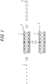
- FIG. 1 is a schematic planar view for illustrating a container manufacturing method according to an embodiment of this disclosure
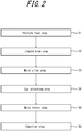
- FIG. 2 is a diagram illustrating an order of each step of the container manufacturing method according to the embodiment.
- reference sign 1 indicates a preform
- reference sign 2 indicates a mold for blow molding
- reference sign 3 indicates a cavity
- reference sign 4 indicates a container after blow molding.
- a mold for blow molding 2 at a position 5 at which a liquid blow step is perform is indicated by a solid line
- the mold for blow molding 2 displaced to a slide position 6 in a mold slide step is indicated by a two-dot chain line.
- the disclosed container manufacturing method includes at least a preform feed step of feeding a bottomed tubular preform 1 formed in advance into a cavity 3 of a mold for blow molding 2; a liquid blow step of filling a pressurized liquid into the preform 1 disposed in the cavity 3 to perform blow molding; an ejection step of ejecting a container 4 after blow molding from the cavity 3; and a mold slide step of displacing the mold for blow molding 2 to a slide position 6.
- the "slide position" is a position that is different at least from the position 5 of the mold for blow molding 2 in the liquid blow step.
- this embodiment is a position obtained by sliding the mold by a predetermined distance from the position 5 of the mold for blow molding 2 in the liquid blow step in the slide direction orthogonal to the transfer direction of the preform 1 in the preform feed step. It is to be noted that, in this embodiment, this slide direction is also orthogonal to the transfer direction (ejection direction) of the container 4 in the ejection step.
- the container 4 is manufactured by performing each step in order of the preform feed step S1, the liquid blow step S2, the mold slide step S3, the cap attaching step S4, the mold return step S5 and the ejection step S6. Further, after the ejection step S6, above described each step is repeated from the preform feed step S1, and the container 4 can be continuously manufactured.
- the ejection step S6 above described each step is repeated from the preform feed step S1, and the container 4 can be continuously manufactured.
- the resin preform 1 formed in advance is fed into the cavity 3 of the mold for blow molding 2 in an opened state.
- a preform that is formed into a bottomed tubular shape like a test tube by a resin material such as polypropylene (PP), polyethylene (PE) and polyethylene terephthalate (PET) can be used as the preform 1 used by the container manufacturing method according to this embodiment.
- the preform 1 may be formed by laminating two or more types of resins.
- the preform 1 may be formed by injection molding using a mold for injection molding or by compression molding using a mold for compression molding, but it is not limited thereto, and the preform 1 formed by a variety of methods may be used.
- the preform 1 is heated by a heating furnace or the like provided with a heater, for example, adjusted to or kept at a temperature that is suitable for liquid blow molding, in other words, a temperature at which a stretching effect is expressed, and fed to the mold for blow molding 2. It is to be noted that, right after the preform 1 is manufactured, the heat caused by heating during injection molding still remains in the preform 1. Thus, by using this, the preform 1 is fed to the mold for blow molding 2 right after being manufactured, and a heating process by a heating furnace or the like can be omitted.
- a preform transfer device can be used to transfer the preform 1 into the cavity 3, and the preform 1 is transferred from the heating furnace into the cavity 3, for example, through a linear path.
- the direction of the linear path is the same as the longitudinal direction of the mold 2, in other words, the alignment direction of a plurality of cavities 3 disposed in series.
- the preform transfer device may be configured, for example, such that it includes a plurality of grippers (in this example, six, which is the same as the number of the cavity 3) capable of gripping a mouth of the preform 1.
- the preform transfer device transfers each preform 1 to its corresponding cavity 3 by gripping, for example, a mouth (neck ring, etc.) of each of six preforms 1 disposed in series by each gripper.
- the mold for blow molding 2 may be displaced to the position close to the heating furnace or to an injection molding device of the preform 1. In this case, after the preform 1 is placed in the cavity 3, the mold for blow molding 2 is displaced to the position 5 at which the liquid blow step S2 is performed, and the liquid blow step S2 is performed.
- the mold for blow molding 2 is a batch-type mold including six cavities 3 disposed linearly in series as illustrated in FIG. 1 , for example.
- the mold for blow molding 2 can be opened right and left (in the horizontal direction), and by opening the mold for blow molding 2, each cavity 3 is released at a time and each container 4 after blow molding can be ejected from the mold for blow molding 2.
- preforms 1 are inserted into cavities 3 respectively with each mold for blow molding 2 opened, and subsequently each mold for blow molding 2 is clamped.
- each preform 1 can be placed in each cavity 3.
- the upper surface of the mold for blow molding 2 is opened upward, and the mouth of the preform 1 is disposed in the opening.
- a nozzle unit is provided on top of the mold for blow molding 2, and the nozzle unit is connected to a pressurized liquid feed machine.
- the pressurized liquid feed machine can feed, through the nozzle unit, a liquid pressurized to a pressure suitable for liquid blow molding to a plurality of preforms 1 disposed in each cavity 3 of the mold for blow molding 2.
- the pressurized liquid feed machine may be configured such that it includes a plunger pump actuated by a servo motor, for example.
- the nozzle unit is vertically movable and can come in contact with the upper surface of the mold for blow molding 2. Further, the nozzle unit includes a plurality (six in this embodiment) of nozzles (not illustrated). The nozzles are fitted into the mouth of the preform 1 placed in each cavity 3 of the mold 2 when they come in contact with the upper surface of the mold for blow molding 2. Then a pressurized liquid fed from the pressurized liquid feed machine can be fed into the preform 1 through the nozzles.
- the nozzle unit may be configured such that it includes a stretching rod configured to axially stretch the preform 1 when liquid blow molding is performed.
- the pressurized liquid feed machine may be configured such that it includes a liquid temperature adjusting device that circulates a liquid in the nozzle unit while maintaining the temperature of the liquid constant.
- content liquids such as beverages, cosmetics and chemicals filled finally in bottles as end-products may be used, and as a result of this, a process of filling content liquid into a container after molding may be omitted.
- the manufacturing process of the container and the structure of the container manufacturing device can be simplified.
- the mold for blow molding 2 is slid to the above described slide position 6.
- the mold for blow molding 2 is slid along with the container 4 that is blow molded in the liquid blow step S2.
- a guide rail is provided on the bottom, the top or the side of the mold for blow molding 2, and along the rail the mold for blow molding 2 is displaced.
- the slide direction is a horizontal direction that is orthogonal to the transfer direction of the preform 1.
- the slide position 6 can be a position that is not overlapped with the nozzle unit and the preform transfer device. As a result of this, equipment such as a nozzle unit and a preform transfer device does not block the up and down direction of the mold for blow molding 2 at the slide position 6, which allows for easy attachment of a cap to the mouth from the top of the container 4.
- a cap is attached to the mouth of the container 4.
- the cap attaching step S4 is performed at the slide position 6.
- the cap attaching step S4 is performed by turning the cap, and when the cap and the mouth are engaged in an undercut manner, the cap attaching step S4 is performed by capping or the like.
- a cap is attached with the container 4 held in a mold.
- the mold for blow molding 2 is returned to the position 5 at which the liquid blow step S2 is performed.
- the mold is slid in the direction opposite to that of the mold slide step S3, and a guide rail or the like may be used as with the mold slide step S3.
- the container 4 is ejected from the mold for blow molding 2.
- the container 4 with a cap attached thereto is ejected.
- the container 4 disposed in the cavity 3 is transferred, along a linear path, by a transfer device provided separately from the preform transfer device.
- the transfer direction of the container 4 is in parallel with (in line with) the transfer direction of the preform 1 in the preform feed step S1, and is orthogonal to the slide direction in the above described mold slide step S3.
- the ejection step S6 may be configured such that, before the mold return step S5, the mold for blow molding 2 is opened at the slide position 6 to eject the container 4 from the cavity 3. In this case, the mold return step S5 is performed after the container 4 is ejected from the cavity 3.
- the mold for blow molding 2 is slid to the slide position 6 that is different from the position 5 of the mold in the preform feed step S1 and the liquid blow step S2, and thus the cap attaching step S4 can be easily performed at a position where the mold is not overlapped with the nozzle unit or the like.
- the cap attaching step S4 can be performed before the ejection step S6 of ejecting the container 4 from the cavity 3 of the mold for blow molding 2, which allows for preventing the content liquid from spilling out of the container 4 in the ejection step S6.
- a decoration step S7 may be added.
- a label bearing characters and designs for example, is inserted from top, bottom or side of the opened mold for blow molding 2.
- the mold for blow molding 2 is displaced to the position 5 at which the liquid blow step S2 is performed (mold return step S5), and thus a label can be adhered to the outer surface of the container 4 after blow molding through the preform feed step S1 and the liquid blow step S2.
- a process of adhering a label to the outer surface of a container after the container is ejected from the mold for blow molding 2 is no more necessary, and a work for decoration can be simplified.
- the mold is opened at the slide position 6 and the ejection step S6 is performed.
- the decoration step S7 a label is inserted into the cavity 3 of the mold 2 from which the container 4 is ejected, after that the mold return step S5 is performed, and each step is repeated again from the preform feed step S1.
- the method is configured in the above described manner, it is no longer necessary to perform the mold slide step S3 and the mold return step S5 twice for each in one manufacturing cycle, and thus the manufacturing efficiency can be increased.
- the decoration step S7 for example, printing and transfer capable of being performed in the mold 2 can be performed.
- the mold slide step S3 is performed after the preform feed step S1 and the liquid blow step S2, and the cap attaching step S4 is performed.
- the mold slide step S3 is provided before the preform feed step S1, and a label is disposed in advance in the cavity 3 of the mold for blow molding 2, and a cap is attached after the ejection step S6.
- the mold slide step S3 is performed, and after that, as the decoration step S7, a label is disposed in the cavity 3 of the mold for blow molding 2 located at the slide position 6.
- the mold return step S5 is performed to return the mold for blow molding 2 to its original position (the position 5 at which the liquid blow step S2 is performed).
- the preform feed step S1 the preform 1 is fed to the inside of the label disposed in advance in the cavity 3 and is clamped.
- the liquid blow step S2 is performed.
- the label is disposed in close adherence to the outer periphery thereof.
- the container 4 is ejected in the ejection step S6, and after that a cap is attached.
- the mold slide step S3 is performed again after the liquid blow step S2 and before the ejection step S6 such that the ejection step S6 is performed with the mold for blow molding 2 disposed at the slide position 6.
- FIG. 4 illustrates still another embodiment, in which the decoration step and the cap attaching step or the like are performed after the ejection step S6.
- the mold slide step S3 is performed after the preform feed step S1 and the liquid blow step S2, the ejection step S6 is performed at the slide position 6, and after that the mold return step S5 is performed.
- a gripper of a transfer device of the container 4 can be easily inserted from the top of the mold for blow molding 2.
- FIG. 5 is a schematic planar view for illustrating a container manufacturing method according to yet another embodiment of this disclosure
- FIG. 6 is a diagram illustrating an order of each step of the container manufacturing method.
- two molds for blow molding 2a and 2b configured to be slidable to the slide positions 6a and 6b different from each other are alternately used to perform the liquid blow step S2.
- the position 5 at which the liquid blow step S2 is performed is located on a transfer path of the preform 1, for example, and the two molds for blow molding 2a and 2b are configured to be slidable to the slide positions 6a and 6b, respectively, such that the position 5 at which the liquid blow step S2 is performed is located between them.
- the preform feed step S1 and the liquid blow step S2 are performed by using the other mold for blow molding 2b located at the position 5. Further, as illustrated in FIG. 5 with a two-dot chain line, while the other mold for blow molding 2b is located at the second slide position 6b, the preform feed step S1 and the liquid blow step S2 are performed by using the one mold for blow molding 2a located at the position 5. It is to be noted that, as illustrated in FIG.
- each of the molds for blow molding 2a and 2b can continuously manufacture the container 4 by repeating in order of the preform feed step S1, the liquid blow step S2, the mold slide step S3 (S3'), the ejection step S6 (S6') and the mold return step S5 (S5').
- the preform feed step S1 is performed at the position 5 at which the liquid blow step S2 is performed, and the ejection step S6 (S6') of the container 4 is performed at respective slide positions 6a and 6b.
- the above described decoration step S7 and cap attaching step S4 may be performed at respective slide positions 6a and 6b.
- the preform feed step S1 and the ejection step S6 (S6') may be performed at respective slide positions 6a and 6b, or the preform feed step S1 may be performed at respective slide positions 6a and 6b, and the ejection step S6 (S6') may be performed at the position 5 at which the liquid blow step S2 is performed.
- the liquid blow step S2 is performed by alternately using the two molds for blow molding 2a and 2b, which allows, while one mold for blow molding 2a of the two performs the ejection step S6 or the like at the slide position 6a, the liquid blow step S2 can be performed by using the other mold for blow molding 2b.
- the manufacturing efficiency of the container 4 can be increased.
- one transfer device is used for the preform 1.
- the overall manufacturing device cost can be reduced.
- the mold slide step S3 of one mold for blow molding 2a and the mold return step S5' of the other mold for blow molding 2b are performed simultaneously.
- the mold return step S5 of one mold for blow molding 2a and the mold slide step S3' of the other mold for blow molding 2b are performed simultaneously.
- FIG. 7 is a schematic planar view for illustrating a container manufacturing method according to further embodiment of this disclosure and FIG. 8 is a diagram illustrating an order of each step of the container manufacturing method according to the embodiment.
- the preform feed step S1 and the ejection step S6 are performed with the mold for blow molding 2 located at the slide position 6. More specifically, as illustrated in FIG. 8 , as the decoration step S7, a label is inserted into the cavity 3 with the mold for blow molding 2 located at the slide position 6, and subsequently the preform feed step S1 is performed. Then, the mold return step S5 is performed, in which the mold for blow molding 2 is displaced from the slide position 6 to the position 5 at which the liquid blow step S2 is performed.
- the mold for blow molding 2 is slid to the slide position 6 in the mold slide step S3, and the cap attaching step S4 is performed at the slide position 6. Then the ejection step S6 is performed at the end. It is to be noted that the decoration step S7 is not performed, and decoration may be performed after the ejection step S6.
- the ejection step S6 may be performed at the position 5 to eject a container from the mold 2, and a cap may be attached to the container.
- the mold slide step S3 is performed after the ejection step S6 to slide the mold for blow molding 2 from the position 5 to the slide position 6, and each step is performed again starting from the decoration step S7 (or the preform feed step S1).
- the mold for blow molding 2 is provided with six cavities 3 disposed in series.
- the number and the arrangement of the cavity 3 may be optionally set, and the mold for blow molding 2 may have at least one cavity 3.
- the sliding direction of the mold for blow molding 2 is not limited to the direction orthogonal to the transfer direction of the preform 1, and it may be optionally set such as a serial direction (linear direction) or the like.
Landscapes
- Engineering & Computer Science (AREA)
- Manufacturing & Machinery (AREA)
- Mechanical Engineering (AREA)
- Blow-Moulding Or Thermoforming Of Plastics Or The Like (AREA)
- Moulds For Moulding Plastics Or The Like (AREA)
Abstract
Description
- This disclosure relates to a container manufacturing method of manufacturing a resin container, and in particular to a method of manufacturing a container of a predetermined shape by liquid blow molding a resin preform.
- Resin containers, typical examples of which are oriented polypropylene (OPP) bottles and polyethylene terephthalate (PET) bottles, are used for a variety of applications such as beverages, food products, cosmetic products or the like. Such a container is generally manufactured by manufacturing a bottomed tubular preform through injection molding or compression molding of a thermoplastic resin, heating the preform to temperatures at which stretching effect can be expressed, and molding the heated preform into a predetermined shape through blow molding using a mold for blow molding.
- As blow molding of a preform, liquid blow molding in which blow molding is performed by feeding a pressurized liquid instead of a pressurized air into a preform is known. In the liquid blow molding, as a liquid used for blow molding, content liquid such as beverages, cosmetic products and pharmaceutical products to be filled in a container as an end product is used. Thus the step of filling the content liquid into a container may be omitted, and the manufacturing process and the configuration of the manufacturing device may be simplified.
- As a manufacturing method of a resin container including the above described liquid blow molding, a method of blow molding a plurality of preforms simultaneously by using a batch-type mold provided with a plurality of cavities disposed in series is known (see, for example, PTL 1).
- In the above described manufacturing method, a plurality of preforms disposed in series at predetermined pitches are respectively fed into mold cavities in an opened state by a transfer device or the like and are clamped. After that, a pressurized liquid is fed from a nozzle unit located on top of the mold to a preform placed in each cavity, and liquid blow molding is performed. Subsequently the mold is opened and a container after blow molding is ejected by a transfer device or the like.
- PTL 1:
JP2016032924A - In the above described container manufacturing method, a nozzle unit or the like configured to fill a liquid is disposed on top of a mold for blow molding. Thus, for example, before an ejection step of ejecting a mold from a container, it is difficult to perform a decoration step of inserting a label bearing characters or designs into a cavity from the top of the mold and decorating the outer surface of the container and a cap attaching step of attaching a cap to a mouth of the container from the top of the container that is held in the mold. Further, when a container after blow molding is ejected from the cavity of the mold, the ejecting direction and method are limited due to the presence of a nozzle unit or the like. Thus there is still room for improvement in terms of increase in container manufacturing efficiency.
- Therefore this disclosure is to propose a resin container manufacturing method that allows, in a resin container manufacturing method by liquid blow molding using a batch-type mold, to increase the container manufacturing efficiency.
- The disclosed container manufacturing method is a container manufacturing method of manufacturing a resin container, the method including:
- a preform feed step of feeding a preform formed into a bottomed tubular shape by a resin material into a cavity of a batch-type mold for blow molding;
- a liquid blow step of filling a pressurized liquid into the preform disposed in the cavity to perform blow molding; and
- an ejection step of ejecting a container after blow molding from the cavity, wherein
- the method further includes a mold slide step of sliding the mold for blow molding to a slide position that is different from a position of the mold for blow molding in the liquid blow step.
- It is to be noted that, in the disclosed container manufacturing method, preferably, the mold for blow molding has a plurality of the cavities disposed in series.
- Further, in the disclosed container manufacturing method, preferably, the method includes a decoration step of applying a decoration to an outer surface of the container with the mold for blow molding located at the slide position.
- Further, in the disclosed container manufacturing method, preferably, the method includes a cap attaching step of attaching a cap to a mouth of the container with the mold for blow molding located at the slide position.
- Further, in the disclosed container manufacturing method, preferably, the ejection step is performed with the mold for blow molding located at the slide position.
- Further, in the disclosed container manufacturing method, preferably, a slide direction of the mold for blow molding in the mold slide step is orthogonal to a transfer direction of the preform in the preform feed step.
- Further, in the disclosed container manufacturing method, preferably, the slide direction of the mold for blow molding in the mold slide step is orthogonal to a transfer direction of a container after blow molding in the ejection step.
- Further, in the disclosed container manufacturing method, preferably, the liquid blow step is performed by alternately using two of the molds for blow molding, wherein
while one of the molds for blow molding is located at a first slide position, the other mold for blow molding performs the liquid blow step; and
while the other mold for blow molding is located at a second slide position, the one of the molds for blow molding performs the liquid blow step. - According to this disclosure, in a method of manufacturing a resin container by liquid blow molding using a batch-type mold, a manufacturing method of resin container that enables a container manufacturing efficiency to be increased can be provided.
- In the accompanying drawings:
-
FIG. 1 is a schematic planar view for illustrating a container manufacturing method according to an embodiment of this disclosure; -
FIG. 2 is a diagram illustrating an order of each step of the container manufacturing method according to the embodiment of this disclosure; -
FIG. 3 is a diagram illustrating an order of each step of the container manufacturing method according to another embodiment of this disclosure; -
FIG. 4 is a diagram illustrating an order of each step of a container manufacturing method according to still another embodiment of this disclosure; -
FIG. 5 is a schematic planar view for illustrating a container manufacturing method according to yet another embodiment of this disclosure; -
FIG. 6 is a diagram illustrating an order of each step of the container manufacturing method according to the embodiment inFIG. 5 ; -
FIG. 7 is a schematic planar view for illustrating a container manufacturing method according to further embodiment of this disclosure; and -
FIG. 8 is a diagram illustrating an order of each step of the container manufacturing method according to the embodiment inFIG. 7 . - This disclosure will be illustrated in more detail below with reference to drawings.
FIG. 1 is a schematic planar view for illustrating a container manufacturing method according to an embodiment of this disclosure, andFIG. 2 is a diagram illustrating an order of each step of the container manufacturing method according to the embodiment. - In
FIG. 1 ,reference sign 1 indicates a preform,reference sign 2 indicates a mold for blow molding,reference sign 3 indicates a cavity andreference sign 4 indicates a container after blow molding. Further, inFIG. 1 , a mold forblow molding 2 at aposition 5 at which a liquid blow step is perform is indicated by a solid line, and the mold forblow molding 2 displaced to aslide position 6 in a mold slide step is indicated by a two-dot chain line. - Here, the disclosed container manufacturing method includes at least a preform feed step of feeding a bottomed
tubular preform 1 formed in advance into acavity 3 of a mold forblow molding 2; a liquid blow step of filling a pressurized liquid into thepreform 1 disposed in thecavity 3 to perform blow molding; an ejection step of ejecting acontainer 4 after blow molding from thecavity 3; and a mold slide step of displacing the mold forblow molding 2 to aslide position 6. Here, the "slide position" is a position that is different at least from theposition 5 of the mold forblow molding 2 in the liquid blow step. In this embodiment, it is a position obtained by sliding the mold by a predetermined distance from theposition 5 of the mold forblow molding 2 in the liquid blow step in the slide direction orthogonal to the transfer direction of thepreform 1 in the preform feed step. It is to be noted that, in this embodiment, this slide direction is also orthogonal to the transfer direction (ejection direction) of thecontainer 4 in the ejection step. - In this embodiment, as illustrated in
FIG. 2 , thecontainer 4 is manufactured by performing each step in order of the preform feed step S1, the liquid blow step S2, the mold slide step S3, the cap attaching step S4, the mold return step S5 and the ejection step S6. Further, after the ejection step S6, above described each step is repeated from the preform feed step S1, and thecontainer 4 can be continuously manufactured. Each process of the container manufacturing method will be described below. - In the preform feed step S1, the
resin preform 1 formed in advance is fed into thecavity 3 of the mold forblow molding 2 in an opened state. Here, as thepreform 1 used by the container manufacturing method according to this embodiment, a preform that is formed into a bottomed tubular shape like a test tube by a resin material such as polypropylene (PP), polyethylene (PE) and polyethylene terephthalate (PET) can be used. Further, thepreform 1 may be formed by laminating two or more types of resins. Thepreform 1 may be formed by injection molding using a mold for injection molding or by compression molding using a mold for compression molding, but it is not limited thereto, and thepreform 1 formed by a variety of methods may be used. - The
preform 1 is heated by a heating furnace or the like provided with a heater, for example, adjusted to or kept at a temperature that is suitable for liquid blow molding, in other words, a temperature at which a stretching effect is expressed, and fed to the mold forblow molding 2. It is to be noted that, right after thepreform 1 is manufactured, the heat caused by heating during injection molding still remains in thepreform 1. Thus, by using this, thepreform 1 is fed to the mold forblow molding 2 right after being manufactured, and a heating process by a heating furnace or the like can be omitted. A preform transfer device can be used to transfer thepreform 1 into thecavity 3, and thepreform 1 is transferred from the heating furnace into thecavity 3, for example, through a linear path. The direction of the linear path (transfer direction) is the same as the longitudinal direction of themold 2, in other words, the alignment direction of a plurality ofcavities 3 disposed in series. The preform transfer device may be configured, for example, such that it includes a plurality of grippers (in this example, six, which is the same as the number of the cavity 3) capable of gripping a mouth of thepreform 1. In this case, the preform transfer device transfers eachpreform 1 to itscorresponding cavity 3 by gripping, for example, a mouth (neck ring, etc.) of each of sixpreforms 1 disposed in series by each gripper. It is to be noted that, in the preform feed step S1, the mold forblow molding 2 may be displaced to the position close to the heating furnace or to an injection molding device of thepreform 1. In this case, after thepreform 1 is placed in thecavity 3, the mold forblow molding 2 is displaced to theposition 5 at which the liquid blow step S2 is performed, and the liquid blow step S2 is performed. - In the liquid blow step S2, a pressurized liquid is fed to each
preform 1 fed into eachcavity 3 and liquid blow molding is performed. Here, the mold forblow molding 2 is a batch-type mold including sixcavities 3 disposed linearly in series as illustrated inFIG. 1 , for example. The mold forblow molding 2 can be opened right and left (in the horizontal direction), and by opening the mold forblow molding 2, eachcavity 3 is released at a time and eachcontainer 4 after blow molding can be ejected from the mold forblow molding 2. Further, preforms 1 are inserted intocavities 3 respectively with each mold forblow molding 2 opened, and subsequently each mold forblow molding 2 is clamped. Thus eachpreform 1 can be placed in eachcavity 3. The upper surface of the mold forblow molding 2 is opened upward, and the mouth of thepreform 1 is disposed in the opening. - A nozzle unit is provided on top of the mold for
blow molding 2, and the nozzle unit is connected to a pressurized liquid feed machine. The pressurized liquid feed machine can feed, through the nozzle unit, a liquid pressurized to a pressure suitable for liquid blow molding to a plurality ofpreforms 1 disposed in eachcavity 3 of the mold forblow molding 2. The pressurized liquid feed machine may be configured such that it includes a plunger pump actuated by a servo motor, for example. - The nozzle unit is vertically movable and can come in contact with the upper surface of the mold for
blow molding 2. Further, the nozzle unit includes a plurality (six in this embodiment) of nozzles (not illustrated). The nozzles are fitted into the mouth of thepreform 1 placed in eachcavity 3 of themold 2 when they come in contact with the upper surface of the mold forblow molding 2. Then a pressurized liquid fed from the pressurized liquid feed machine can be fed into thepreform 1 through the nozzles. - It is to be noted that the nozzle unit may be configured such that it includes a stretching rod configured to axially stretch the
preform 1 when liquid blow molding is performed. Further, the pressurized liquid feed machine may be configured such that it includes a liquid temperature adjusting device that circulates a liquid in the nozzle unit while maintaining the temperature of the liquid constant. - As a liquid for liquid blow molding fed into the
preform 1 by the pressurized liquid feed machine, content liquids such as beverages, cosmetics and chemicals filled finally in bottles as end-products may be used, and as a result of this, a process of filling content liquid into a container after molding may be omitted. Thus the manufacturing process of the container and the structure of the container manufacturing device can be simplified. - In the mold slide step S3, the mold for
blow molding 2 is slid to the above describedslide position 6. In this embodiment, the mold forblow molding 2 is slid along with thecontainer 4 that is blow molded in the liquid blow step S2. It is to be noted that, as a configuration of sliding the mold forblow molding 2, for example, a guide rail is provided on the bottom, the top or the side of the mold forblow molding 2, and along the rail the mold forblow molding 2 is displaced. The slide direction is a horizontal direction that is orthogonal to the transfer direction of thepreform 1. Theslide position 6 can be a position that is not overlapped with the nozzle unit and the preform transfer device. As a result of this, equipment such as a nozzle unit and a preform transfer device does not block the up and down direction of the mold forblow molding 2 at theslide position 6, which allows for easy attachment of a cap to the mouth from the top of thecontainer 4. - In the cap attaching step S4, a cap is attached to the mouth of the
container 4. In this embodiment, the cap attaching step S4 is performed at theslide position 6. Thus there is no nozzle unit or the like on top of the mold forblow molding 2, and therefore a cap can be easily attached. Further, a device for attaching a cap can be easily disposed. It is to be noted that, when the cap and the mouth are connected by screw, for example, the cap attaching step S4 is performed by turning the cap, and when the cap and the mouth are engaged in an undercut manner, the cap attaching step S4 is performed by capping or the like. Preferably, a cap is attached with thecontainer 4 held in a mold. - In the mold return step S5, the mold for
blow molding 2 is returned to theposition 5 at which the liquid blow step S2 is performed. In the mold return step S5, the mold is slid in the direction opposite to that of the mold slide step S3, and a guide rail or the like may be used as with the mold slide step S3. - In the ejection step S6, the
container 4 is ejected from the mold forblow molding 2. In this embodiment, thecontainer 4 with a cap attached thereto is ejected. Thecontainer 4 disposed in thecavity 3 is transferred, along a linear path, by a transfer device provided separately from the preform transfer device. In this embodiment, the transfer direction of thecontainer 4 is in parallel with (in line with) the transfer direction of thepreform 1 in the preform feed step S1, and is orthogonal to the slide direction in the above described mold slide step S3. - It is to be noted that, the ejection step S6 may be configured such that, before the mold return step S5, the mold for
blow molding 2 is opened at theslide position 6 to eject thecontainer 4 from thecavity 3. In this case, the mold return step S5 is performed after thecontainer 4 is ejected from thecavity 3. - As described above, in the container manufacturing method according to this embodiment, the mold for
blow molding 2 is slid to theslide position 6 that is different from theposition 5 of the mold in the preform feed step S1 and the liquid blow step S2, and thus the cap attaching step S4 can be easily performed at a position where the mold is not overlapped with the nozzle unit or the like. Thus, the cap attaching step S4 can be performed before the ejection step S6 of ejecting thecontainer 4 from thecavity 3 of the mold forblow molding 2, which allows for preventing the content liquid from spilling out of thecontainer 4 in the ejection step S6. - It is to be noted that, in this embodiment, a decoration step S7 may be added. In the decoration step S7, a label bearing characters and designs, for example, is inserted from top, bottom or side of the opened mold for
blow molding 2. In other words, after a label is inserted into the mold forblow molding 2 at theslide position 6, the mold forblow molding 2 is displaced to theposition 5 at which the liquid blow step S2 is performed (mold return step S5), and thus a label can be adhered to the outer surface of thecontainer 4 after blow molding through the preform feed step S1 and the liquid blow step S2. As a result of this, a process of adhering a label to the outer surface of a container after the container is ejected from the mold forblow molding 2 is no more necessary, and a work for decoration can be simplified. It is to be noted that, in this case, preferably, after the cap attaching step S4 inFIG. 2 , the mold is opened at theslide position 6 and the ejection step S6 is performed. Further, as the decoration step S7, a label is inserted into thecavity 3 of themold 2 from which thecontainer 4 is ejected, after that the mold return step S5 is performed, and each step is repeated again from the preform feed step S1. When the method is configured in the above described manner, it is no longer necessary to perform the mold slide step S3 and the mold return step S5 twice for each in one manufacturing cycle, and thus the manufacturing efficiency can be increased. It is to be noted that, as the decoration step S7, for example, printing and transfer capable of being performed in themold 2 can be performed. - Another embodiment of this disclosure will be described below. In the above described embodiment, the mold slide step S3 is performed after the preform feed step S1 and the liquid blow step S2, and the cap attaching step S4 is performed. However, in this embodiment, the mold slide step S3 is provided before the preform feed step S1, and a label is disposed in advance in the
cavity 3 of the mold forblow molding 2, and a cap is attached after the ejection step S6. In other words, as illustrated inFIG. 3 , first, the mold slide step S3 is performed, and after that, as the decoration step S7, a label is disposed in thecavity 3 of the mold forblow molding 2 located at theslide position 6. After that, the mold return step S5 is performed to return the mold forblow molding 2 to its original position (theposition 5 at which the liquid blow step S2 is performed). Then, in the preform feed step S1, thepreform 1 is fed to the inside of the label disposed in advance in thecavity 3 and is clamped. After that the liquid blow step S2 is performed. In this case, when thepreform 1 is expanded and deformed in the liquid blow step S2, the label is disposed in close adherence to the outer periphery thereof. After the liquid blow step S2, thecontainer 4 is ejected in the ejection step S6, and after that a cap is attached. - It is to be noted that, the mold slide step S3 is performed again after the liquid blow step S2 and before the ejection step S6 such that the ejection step S6 is performed with the mold for
blow molding 2 disposed at theslide position 6. -
FIG. 4 illustrates still another embodiment, in which the decoration step and the cap attaching step or the like are performed after the ejection step S6. In this embodiment, the mold slide step S3 is performed after the preform feed step S1 and the liquid blow step S2, the ejection step S6 is performed at theslide position 6, and after that the mold return step S5 is performed. In this manner, when the ejection step S6 is performed at theslide position 6 where a nozzle unit or the like is not overlapped thereon, a gripper of a transfer device of thecontainer 4 can be easily inserted from the top of the mold forblow molding 2. In other words, in the ejection step S6, limitation of the ejecting direction and the ejecting method of thecontainer 4 by the nozzle unit or the like can be prevented. It is to be noted that, when the decoration step is performed after thecontainer 4 is ejected from the mold forblow molding 2 as with this embodiment, in addition to the decoration method using a shrink label and a roller label never before possible in a mold, a decoration method such as a printing never before possible will be possible. -
FIG. 5 is a schematic planar view for illustrating a container manufacturing method according to yet another embodiment of this disclosure, andFIG. 6 is a diagram illustrating an order of each step of the container manufacturing method. In this embodiment, as illustrated inFIG. 5 , two molds forblow molding position 5 at which the liquid blow step S2 is performed is located on a transfer path of thepreform 1, for example, and the two molds forblow molding position 5 at which the liquid blow step S2 is performed is located between them. - As illustrated in
FIG. 5 with a solid line, while one mold forblow molding 2a of the two molds forblow molding blow molding 2b located at theposition 5. Further, as illustrated inFIG. 5 with a two-dot chain line, while the other mold forblow molding 2b is located at thesecond slide position 6b, the preform feed step S1 and the liquid blow step S2 are performed by using the one mold forblow molding 2a located at theposition 5. It is to be noted that, as illustrated inFIG. 6 , each of the molds forblow molding container 4 by repeating in order of the preform feed step S1, the liquid blow step S2, the mold slide step S3 (S3'), the ejection step S6 (S6') and the mold return step S5 (S5'). - In this embodiment, the preform feed step S1 is performed at the
position 5 at which the liquid blow step S2 is performed, and the ejection step S6 (S6') of thecontainer 4 is performed atrespective slide positions 6a and 6b. It is to be noted that, the above described decoration step S7 and cap attaching step S4 may be performed atrespective slide positions 6a and 6b. Further, the preform feed step S1 and the ejection step S6 (S6') may be performed atrespective slide positions 6a and 6b, or the preform feed step S1 may be performed atrespective slide positions 6a and 6b, and the ejection step S6 (S6') may be performed at theposition 5 at which the liquid blow step S2 is performed. - As described above, in this embodiment, the liquid blow step S2 is performed by alternately using the two molds for
blow molding blow molding 2a of the two performs the ejection step S6 or the like at the slide position 6a, the liquid blow step S2 can be performed by using the other mold forblow molding 2b. Thus the manufacturing efficiency of thecontainer 4 can be increased. - Further, in this embodiment, one transfer device is used for the
preform 1. Thus, compared with the case where a transfer device of thepreform 1 is provided for each of the two molds forblow molding - Further, in this embodiment, in terms of further increasing the manufacturing efficiency of the
container 4, as illustrated inFIG. 6 , preferably, the mold slide step S3 of one mold forblow molding 2a and the mold return step S5' of the other mold forblow molding 2b are performed simultaneously. In the same manner, preferably, the mold return step S5 of one mold forblow molding 2a and the mold slide step S3' of the other mold forblow molding 2b are performed simultaneously. -
FIG. 7 is a schematic planar view for illustrating a container manufacturing method according to further embodiment of this disclosure andFIG. 8 is a diagram illustrating an order of each step of the container manufacturing method according to the embodiment. In this embodiment, the preform feed step S1 and the ejection step S6 are performed with the mold forblow molding 2 located at theslide position 6. More specifically, as illustrated inFIG. 8 , as the decoration step S7, a label is inserted into thecavity 3 with the mold forblow molding 2 located at theslide position 6, and subsequently the preform feed step S1 is performed. Then, the mold return step S5 is performed, in which the mold forblow molding 2 is displaced from theslide position 6 to theposition 5 at which the liquid blow step S2 is performed. After the liquid blow step S2, the mold forblow molding 2 is slid to theslide position 6 in the mold slide step S3, and the cap attaching step S4 is performed at theslide position 6. Then the ejection step S6 is performed at the end. It is to be noted that the decoration step S7 is not performed, and decoration may be performed after the ejection step S6. - It is to be noted that, in the container manufacturing method illustrated in
FIG. 8 , after the liquid blow step S2, the ejection step S6 may be performed at theposition 5 to eject a container from themold 2, and a cap may be attached to the container. In this case, the mold slide step S3 is performed after the ejection step S6 to slide the mold forblow molding 2 from theposition 5 to theslide position 6, and each step is performed again starting from the decoration step S7 (or the preform feed step S1). - Needless to say, this disclosure is not limited to the above described embodiments, and may be changed in various manners without departing from the gist thereof.
- For example, in the above described embodiments, the mold for
blow molding 2 is provided with sixcavities 3 disposed in series. However, the number and the arrangement of thecavity 3 may be optionally set, and the mold forblow molding 2 may have at least onecavity 3. Further, the sliding direction of the mold forblow molding 2 is not limited to the direction orthogonal to the transfer direction of thepreform 1, and it may be optionally set such as a serial direction (linear direction) or the like. -
- 1
- Preform
- 2
- Mold for blow molding
- 3
- Cavity
- 4
- Container
- 5
- Position at which a liquid blow step is performed
- 6
- Sliding position
- 6a
- First sliding position
- 6b
- Second sliding position
- S1
- Preform feed step
- S2
- Liquid blow step
- S3
- Mold slide step
- S4
- Cap attaching step
- S5
- Mold return step
- S6
- Ejection step
- S7
- Decoration step
Claims (8)
- A container manufacturing method, comprising:a preform feed step of feeding a preform formed into a bottomed tubular shape by a resin material into a cavity of a batch-type mold for blow molding;a liquid blow step of filling a pressurized liquid into the preform disposed in the cavity to perform blow molding; andan ejection step of ejecting a container after blow molding from the cavity, whereinthe method further comprises a mold slide step of sliding the mold for blow molding to a slide position that is different from a position of the mold for blow molding in the liquid blow step.
- The container manufacturing method according to claim 1, wherein the mold for blow molding has a plurality of the cavities disposed in series.
- The container manufacturing method according to claim 1 or 2, wherein the method includes a decoration step of applying a decoration to an outer surface of the container with the mold for blow molding located at the slide position.
- The container manufacturing method according to any one of claims 1 to 3, wherein the method includes a cap attaching step of attaching a cap to a mouth of the container with the mold for blow molding located at the slide position.
- The container manufacturing method according to any one of claims 1 to 4, wherein the ejection step is performed with the mold for blow molding located at the slide position.
- The container manufacturing method according to any one of claims 1 to 5, wherein a slide direction of the mold for blow molding in the mold slide step is orthogonal to a transfer direction of the preform in the preform feed step.
- The container manufacturing method according to any one of claims 1 to 6, wherein the slide direction of the mold for blow molding in the mold slide step is orthogonal to a transfer direction of the preform after blow molding in the ejection step.
- The container manufacturing method according to any one of claims 1 to 7, wherein in the container manufacturing method of performing the liquid blow step by alternately using two of the molds for blow molding,
while one of the molds for blow molding is located at a first slide position, the other mold for blow molding performs the liquid blow step; and
while the other mold for blow molding is located at a second slide position, the one of the molds for blow molding performs the liquid blow step.
Applications Claiming Priority (2)
| Application Number | Priority Date | Filing Date | Title |
|---|---|---|---|
| JP2016130796A JP6837763B2 (en) | 2016-06-30 | 2016-06-30 | Container manufacturing method |
| PCT/JP2017/017173 WO2018003284A1 (en) | 2016-06-30 | 2017-05-01 | Container manufacturing method |
Publications (3)
| Publication Number | Publication Date |
|---|---|
| EP3479995A1 true EP3479995A1 (en) | 2019-05-08 |
| EP3479995A4 EP3479995A4 (en) | 2020-03-11 |
| EP3479995B1 EP3479995B1 (en) | 2021-08-11 |
Family
ID=60785126
Family Applications (1)
| Application Number | Title | Priority Date | Filing Date |
|---|---|---|---|
| EP17819651.5A Active EP3479995B1 (en) | 2016-06-30 | 2017-05-01 | Container manufacturing method |
Country Status (5)
| Country | Link |
|---|---|
| US (1) | US20190193322A1 (en) |
| EP (1) | EP3479995B1 (en) |
| JP (1) | JP6837763B2 (en) |
| CN (1) | CN109311214B (en) |
| WO (1) | WO2018003284A1 (en) |
Family Cites Families (15)
| Publication number | Priority date | Publication date | Assignee | Title |
|---|---|---|---|---|
| JPS4317819B1 (en) * | 1963-09-03 | 1968-07-29 | ||
| JPS5429548B1 (en) * | 1970-11-13 | 1979-09-25 | ||
| JPS5345366A (en) * | 1976-10-04 | 1978-04-24 | Japan Steel Works Ltd | Blow molding machine |
| JPS5993329A (en) * | 1982-11-18 | 1984-05-29 | Kao Corp | Blow molding method |
| CA1252967A (en) * | 1987-03-23 | 1989-04-25 | Paul M. Oles | Rotary blow molding machine |
| JP4433513B2 (en) * | 1999-04-28 | 2010-03-17 | 東洋製罐株式会社 | Blow molding method and apparatus |
| US6730257B2 (en) * | 2001-02-12 | 2004-05-04 | Owens-Brockway Plastic Products Inc. | Shuttle-type blow molding method and apparatus |
| US7833006B2 (en) * | 2001-02-12 | 2010-11-16 | Graham Packaging Plastic Products, Inc. | Single-sided shuttle-type blow molding apparatus |
| JP5697885B2 (en) * | 2009-09-11 | 2015-04-08 | 日精エー・エス・ビー機械株式会社 | Blow molding machine |
| ES2418152T3 (en) * | 2010-03-13 | 2013-08-12 | Graham Packaging Company, L.P. | Machine for blow molding of containers from a preliminary form using a rotating table that rotates continuously |
| AU2011241466A1 (en) * | 2010-04-12 | 2012-09-20 | Pro Technical Plastic Manufacturing Solutions Pty Ltd | A blow moulding machine and method of blow moulding |
| CA2842850C (en) * | 2011-08-08 | 2019-04-30 | Nestec S.A. | Rotary system for simultaneously blowing and filling plastic containers |
| WO2014173845A1 (en) * | 2013-04-24 | 2014-10-30 | Discma Ag | Method and machine for manufacturing plastic containers |
| JP6313157B2 (en) * | 2014-07-31 | 2018-04-18 | 株式会社吉野工業所 | Blow molding equipment |
| JP6274230B2 (en) * | 2016-02-04 | 2018-02-07 | 東洋製罐株式会社 | Blow molding apparatus and blow molding method |
-
2016
- 2016-06-30 JP JP2016130796A patent/JP6837763B2/en active Active
-
2017
- 2017-05-01 US US16/309,361 patent/US20190193322A1/en not_active Abandoned
- 2017-05-01 EP EP17819651.5A patent/EP3479995B1/en active Active
- 2017-05-01 CN CN201780037805.5A patent/CN109311214B/en active Active
- 2017-05-01 WO PCT/JP2017/017173 patent/WO2018003284A1/en not_active Ceased
Also Published As
| Publication number | Publication date |
|---|---|
| EP3479995B1 (en) | 2021-08-11 |
| EP3479995A4 (en) | 2020-03-11 |
| US20190193322A1 (en) | 2019-06-27 |
| JP6837763B2 (en) | 2021-03-03 |
| CN109311214A (en) | 2019-02-05 |
| JP2018001576A (en) | 2018-01-11 |
| WO2018003284A1 (en) | 2018-01-04 |
| CN109311214B (en) | 2021-07-30 |
Similar Documents
| Publication | Publication Date | Title |
|---|---|---|
| US9211668B2 (en) | Receiving system | |
| CN105121129B (en) | Extension means for forming container necks in machines for forming containers from preforms | |
| EP3269530B1 (en) | Blow molding device | |
| US10166712B2 (en) | Method and apparatus for fabricating containers | |
| EP3466640B1 (en) | Container production method | |
| US10322540B2 (en) | Blow molding device | |
| EP3278952B1 (en) | Container manufacturing device | |
| CN107107452A (en) | Method for producing thermoformed products, installation and machine for carrying out the method | |
| EP3479995B1 (en) | Container manufacturing method | |
| EP3978222B1 (en) | Blow molding device | |
| EP2554355B1 (en) | Apparatus and method for manufacturing containers | |
| EP3488991B1 (en) | Method of manufacturing container by liquid blow molding | |
| EP3488992B1 (en) | Method of manufacturing container by liquid blow-molding |
Legal Events
| Date | Code | Title | Description |
|---|---|---|---|
| STAA | Information on the status of an ep patent application or granted ep patent |
Free format text: STATUS: THE INTERNATIONAL PUBLICATION HAS BEEN MADE |
|
| PUAI | Public reference made under article 153(3) epc to a published international application that has entered the european phase |
Free format text: ORIGINAL CODE: 0009012 |
|
| STAA | Information on the status of an ep patent application or granted ep patent |
Free format text: STATUS: REQUEST FOR EXAMINATION WAS MADE |
|
| 17P | Request for examination filed |
Effective date: 20181211 |
|
| AK | Designated contracting states |
Kind code of ref document: A1 Designated state(s): AL AT BE BG CH CY CZ DE DK EE ES FI FR GB GR HR HU IE IS IT LI LT LU LV MC MK MT NL NO PL PT RO RS SE SI SK SM TR |
|
| AX | Request for extension of the european patent |
Extension state: BA ME |
|
| DAV | Request for validation of the european patent (deleted) | ||
| DAX | Request for extension of the european patent (deleted) | ||
| A4 | Supplementary search report drawn up and despatched |
Effective date: 20200206 |
|
| RIC1 | Information provided on ipc code assigned before grant |
Ipc: B29C 49/46 20060101ALI20200131BHEP Ipc: B29C 49/32 20060101AFI20200131BHEP Ipc: B29C 49/42 20060101ALI20200131BHEP Ipc: B29L 31/00 20060101ALN20200131BHEP Ipc: B29C 49/48 20060101ALI20200131BHEP |
|
| GRAP | Despatch of communication of intention to grant a patent |
Free format text: ORIGINAL CODE: EPIDOSNIGR1 |
|
| STAA | Information on the status of an ep patent application or granted ep patent |
Free format text: STATUS: GRANT OF PATENT IS INTENDED |
|
| RIC1 | Information provided on ipc code assigned before grant |
Ipc: B29L 31/00 20060101ALN20210505BHEP Ipc: B29C 49/42 20060101ALI20210505BHEP Ipc: B29C 49/48 20060101ALI20210505BHEP Ipc: B29C 49/46 20060101ALI20210505BHEP Ipc: B29C 49/32 20060101AFI20210505BHEP |
|
| INTG | Intention to grant announced |
Effective date: 20210518 |
|
| RIN1 | Information on inventor provided before grant (corrected) |
Inventor name: SATO SUMITO Inventor name: MORIKAMI SHIGEKI |
|
| GRAS | Grant fee paid |
Free format text: ORIGINAL CODE: EPIDOSNIGR3 |
|
| GRAA | (expected) grant |
Free format text: ORIGINAL CODE: 0009210 |
|
| STAA | Information on the status of an ep patent application or granted ep patent |
Free format text: STATUS: THE PATENT HAS BEEN GRANTED |
|
| AK | Designated contracting states |
Kind code of ref document: B1 Designated state(s): AL AT BE BG CH CY CZ DE DK EE ES FI FR GB GR HR HU IE IS IT LI LT LU LV MC MK MT NL NO PL PT RO RS SE SI SK SM TR |
|
| REG | Reference to a national code |
Ref country code: CH Ref legal event code: EP |
|
| REG | Reference to a national code |
Ref country code: DE Ref legal event code: R096 Ref document number: 602017043966 Country of ref document: DE |
|
| REG | Reference to a national code |
Ref country code: IE Ref legal event code: FG4D Ref country code: AT Ref legal event code: REF Ref document number: 1418931 Country of ref document: AT Kind code of ref document: T Effective date: 20210915 |
|
| REG | Reference to a national code |
Ref country code: LT Ref legal event code: MG9D |
|
| REG | Reference to a national code |
Ref country code: NL Ref legal event code: MP Effective date: 20210811 |
|
| REG | Reference to a national code |
Ref country code: AT Ref legal event code: MK05 Ref document number: 1418931 Country of ref document: AT Kind code of ref document: T Effective date: 20210811 |
|
| PG25 | Lapsed in a contracting state [announced via postgrant information from national office to epo] |
Ref country code: NO Free format text: LAPSE BECAUSE OF FAILURE TO SUBMIT A TRANSLATION OF THE DESCRIPTION OR TO PAY THE FEE WITHIN THE PRESCRIBED TIME-LIMIT Effective date: 20211111 Ref country code: PT Free format text: LAPSE BECAUSE OF FAILURE TO SUBMIT A TRANSLATION OF THE DESCRIPTION OR TO PAY THE FEE WITHIN THE PRESCRIBED TIME-LIMIT Effective date: 20211213 Ref country code: BG Free format text: LAPSE BECAUSE OF FAILURE TO SUBMIT A TRANSLATION OF THE DESCRIPTION OR TO PAY THE FEE WITHIN THE PRESCRIBED TIME-LIMIT Effective date: 20211111 Ref country code: AT Free format text: LAPSE BECAUSE OF FAILURE TO SUBMIT A TRANSLATION OF THE DESCRIPTION OR TO PAY THE FEE WITHIN THE PRESCRIBED TIME-LIMIT Effective date: 20210811 Ref country code: LT Free format text: LAPSE BECAUSE OF FAILURE TO SUBMIT A TRANSLATION OF THE DESCRIPTION OR TO PAY THE FEE WITHIN THE PRESCRIBED TIME-LIMIT Effective date: 20210811 Ref country code: SE Free format text: LAPSE BECAUSE OF FAILURE TO SUBMIT A TRANSLATION OF THE DESCRIPTION OR TO PAY THE FEE WITHIN THE PRESCRIBED TIME-LIMIT Effective date: 20210811 Ref country code: RS Free format text: LAPSE BECAUSE OF FAILURE TO SUBMIT A TRANSLATION OF THE DESCRIPTION OR TO PAY THE FEE WITHIN THE PRESCRIBED TIME-LIMIT Effective date: 20210811 Ref country code: HR Free format text: LAPSE BECAUSE OF FAILURE TO SUBMIT A TRANSLATION OF THE DESCRIPTION OR TO PAY THE FEE WITHIN THE PRESCRIBED TIME-LIMIT Effective date: 20210811 Ref country code: FI Free format text: LAPSE BECAUSE OF FAILURE TO SUBMIT A TRANSLATION OF THE DESCRIPTION OR TO PAY THE FEE WITHIN THE PRESCRIBED TIME-LIMIT Effective date: 20210811 Ref country code: ES Free format text: LAPSE BECAUSE OF FAILURE TO SUBMIT A TRANSLATION OF THE DESCRIPTION OR TO PAY THE FEE WITHIN THE PRESCRIBED TIME-LIMIT Effective date: 20210811 |
|
| PG25 | Lapsed in a contracting state [announced via postgrant information from national office to epo] |
Ref country code: PL Free format text: LAPSE BECAUSE OF FAILURE TO SUBMIT A TRANSLATION OF THE DESCRIPTION OR TO PAY THE FEE WITHIN THE PRESCRIBED TIME-LIMIT Effective date: 20210811 Ref country code: LV Free format text: LAPSE BECAUSE OF FAILURE TO SUBMIT A TRANSLATION OF THE DESCRIPTION OR TO PAY THE FEE WITHIN THE PRESCRIBED TIME-LIMIT Effective date: 20210811 Ref country code: GR Free format text: LAPSE BECAUSE OF FAILURE TO SUBMIT A TRANSLATION OF THE DESCRIPTION OR TO PAY THE FEE WITHIN THE PRESCRIBED TIME-LIMIT Effective date: 20211112 |
|
| PG25 | Lapsed in a contracting state [announced via postgrant information from national office to epo] |
Ref country code: NL Free format text: LAPSE BECAUSE OF FAILURE TO SUBMIT A TRANSLATION OF THE DESCRIPTION OR TO PAY THE FEE WITHIN THE PRESCRIBED TIME-LIMIT Effective date: 20210811 |
|
| PG25 | Lapsed in a contracting state [announced via postgrant information from national office to epo] |
Ref country code: DK Free format text: LAPSE BECAUSE OF FAILURE TO SUBMIT A TRANSLATION OF THE DESCRIPTION OR TO PAY THE FEE WITHIN THE PRESCRIBED TIME-LIMIT Effective date: 20210811 |
|
| REG | Reference to a national code |
Ref country code: DE Ref legal event code: R097 Ref document number: 602017043966 Country of ref document: DE |
|
| PG25 | Lapsed in a contracting state [announced via postgrant information from national office to epo] |
Ref country code: SM Free format text: LAPSE BECAUSE OF FAILURE TO SUBMIT A TRANSLATION OF THE DESCRIPTION OR TO PAY THE FEE WITHIN THE PRESCRIBED TIME-LIMIT Effective date: 20210811 Ref country code: SK Free format text: LAPSE BECAUSE OF FAILURE TO SUBMIT A TRANSLATION OF THE DESCRIPTION OR TO PAY THE FEE WITHIN THE PRESCRIBED TIME-LIMIT Effective date: 20210811 Ref country code: RO Free format text: LAPSE BECAUSE OF FAILURE TO SUBMIT A TRANSLATION OF THE DESCRIPTION OR TO PAY THE FEE WITHIN THE PRESCRIBED TIME-LIMIT Effective date: 20210811 Ref country code: EE Free format text: LAPSE BECAUSE OF FAILURE TO SUBMIT A TRANSLATION OF THE DESCRIPTION OR TO PAY THE FEE WITHIN THE PRESCRIBED TIME-LIMIT Effective date: 20210811 Ref country code: CZ Free format text: LAPSE BECAUSE OF FAILURE TO SUBMIT A TRANSLATION OF THE DESCRIPTION OR TO PAY THE FEE WITHIN THE PRESCRIBED TIME-LIMIT Effective date: 20210811 Ref country code: AL Free format text: LAPSE BECAUSE OF FAILURE TO SUBMIT A TRANSLATION OF THE DESCRIPTION OR TO PAY THE FEE WITHIN THE PRESCRIBED TIME-LIMIT Effective date: 20210811 |
|
| PLBE | No opposition filed within time limit |
Free format text: ORIGINAL CODE: 0009261 |
|
| STAA | Information on the status of an ep patent application or granted ep patent |
Free format text: STATUS: NO OPPOSITION FILED WITHIN TIME LIMIT |
|
| 26N | No opposition filed |
Effective date: 20220512 |
|
| PG25 | Lapsed in a contracting state [announced via postgrant information from national office to epo] |
Ref country code: IT Free format text: LAPSE BECAUSE OF FAILURE TO SUBMIT A TRANSLATION OF THE DESCRIPTION OR TO PAY THE FEE WITHIN THE PRESCRIBED TIME-LIMIT Effective date: 20210811 |
|
| PG25 | Lapsed in a contracting state [announced via postgrant information from national office to epo] |
Ref country code: SI Free format text: LAPSE BECAUSE OF FAILURE TO SUBMIT A TRANSLATION OF THE DESCRIPTION OR TO PAY THE FEE WITHIN THE PRESCRIBED TIME-LIMIT Effective date: 20210811 |
|
| REG | Reference to a national code |
Ref country code: CH Ref legal event code: PL |
|
| REG | Reference to a national code |
Ref country code: BE Ref legal event code: MM Effective date: 20220531 |
|
| PG25 | Lapsed in a contracting state [announced via postgrant information from national office to epo] |
Ref country code: MC Free format text: LAPSE BECAUSE OF FAILURE TO SUBMIT A TRANSLATION OF THE DESCRIPTION OR TO PAY THE FEE WITHIN THE PRESCRIBED TIME-LIMIT Effective date: 20210811 Ref country code: LU Free format text: LAPSE BECAUSE OF NON-PAYMENT OF DUE FEES Effective date: 20220501 Ref country code: LI Free format text: LAPSE BECAUSE OF NON-PAYMENT OF DUE FEES Effective date: 20220531 Ref country code: CH Free format text: LAPSE BECAUSE OF NON-PAYMENT OF DUE FEES Effective date: 20220531 |
|
| PG25 | Lapsed in a contracting state [announced via postgrant information from national office to epo] |
Ref country code: IE Free format text: LAPSE BECAUSE OF NON-PAYMENT OF DUE FEES Effective date: 20220501 |
|
| PG25 | Lapsed in a contracting state [announced via postgrant information from national office to epo] |
Ref country code: BE Free format text: LAPSE BECAUSE OF NON-PAYMENT OF DUE FEES Effective date: 20220531 |
|
| PG25 | Lapsed in a contracting state [announced via postgrant information from national office to epo] |
Ref country code: HU Free format text: LAPSE BECAUSE OF FAILURE TO SUBMIT A TRANSLATION OF THE DESCRIPTION OR TO PAY THE FEE WITHIN THE PRESCRIBED TIME-LIMIT; INVALID AB INITIO Effective date: 20170501 |
|
| PG25 | Lapsed in a contracting state [announced via postgrant information from national office to epo] |
Ref country code: MK Free format text: LAPSE BECAUSE OF FAILURE TO SUBMIT A TRANSLATION OF THE DESCRIPTION OR TO PAY THE FEE WITHIN THE PRESCRIBED TIME-LIMIT Effective date: 20210811 Ref country code: CY Free format text: LAPSE BECAUSE OF FAILURE TO SUBMIT A TRANSLATION OF THE DESCRIPTION OR TO PAY THE FEE WITHIN THE PRESCRIBED TIME-LIMIT Effective date: 20210811 |
|
| PG25 | Lapsed in a contracting state [announced via postgrant information from national office to epo] |
Ref country code: TR Free format text: LAPSE BECAUSE OF FAILURE TO SUBMIT A TRANSLATION OF THE DESCRIPTION OR TO PAY THE FEE WITHIN THE PRESCRIBED TIME-LIMIT Effective date: 20210811 |
|
| PG25 | Lapsed in a contracting state [announced via postgrant information from national office to epo] |
Ref country code: MT Free format text: LAPSE BECAUSE OF FAILURE TO SUBMIT A TRANSLATION OF THE DESCRIPTION OR TO PAY THE FEE WITHIN THE PRESCRIBED TIME-LIMIT Effective date: 20210811 |
|
| PGFP | Annual fee paid to national office [announced via postgrant information from national office to epo] |
Ref country code: DE Payment date: 20250402 Year of fee payment: 9 |
|
| PGFP | Annual fee paid to national office [announced via postgrant information from national office to epo] |
Ref country code: FR Payment date: 20250401 Year of fee payment: 9 |
|
| PGFP | Annual fee paid to national office [announced via postgrant information from national office to epo] |
Ref country code: GB Payment date: 20260323 Year of fee payment: 10 |