EP3479794A1 - Dental prosthesis - Google Patents
Dental prosthesis Download PDFInfo
- Publication number
- EP3479794A1 EP3479794A1 EP17819653.1A EP17819653A EP3479794A1 EP 3479794 A1 EP3479794 A1 EP 3479794A1 EP 17819653 A EP17819653 A EP 17819653A EP 3479794 A1 EP3479794 A1 EP 3479794A1
- Authority
- EP
- European Patent Office
- Prior art keywords
- dental prosthesis
- crown
- abutment tooth
- shape
- grooves
- Prior art date
- Legal status (The legal status is an assumption and is not a legal conclusion. Google has not performed a legal analysis and makes no representation as to the accuracy of the status listed.)
- Withdrawn
Links
Images

Classifications
-
- A—HUMAN NECESSITIES
- A61—MEDICAL OR VETERINARY SCIENCE; HYGIENE
- A61C—DENTISTRY; APPARATUS OR METHODS FOR ORAL OR DENTAL HYGIENE
- A61C13/00—Dental prostheses; Making same
- A61C13/08—Artificial teeth; Making same
-
- A—HUMAN NECESSITIES
- A61—MEDICAL OR VETERINARY SCIENCE; HYGIENE
- A61C—DENTISTRY; APPARATUS OR METHODS FOR ORAL OR DENTAL HYGIENE
- A61C13/00—Dental prostheses; Making same
-
- A—HUMAN NECESSITIES
- A61—MEDICAL OR VETERINARY SCIENCE; HYGIENE
- A61C—DENTISTRY; APPARATUS OR METHODS FOR ORAL OR DENTAL HYGIENE
- A61C13/00—Dental prostheses; Making same
- A61C13/08—Artificial teeth; Making same
- A61C13/083—Porcelain or ceramic teeth
-
- A—HUMAN NECESSITIES
- A61—MEDICAL OR VETERINARY SCIENCE; HYGIENE
- A61C—DENTISTRY; APPARATUS OR METHODS FOR ORAL OR DENTAL HYGIENE
- A61C13/00—Dental prostheses; Making same
- A61C13/08—Artificial teeth; Making same
- A61C13/087—Artificial resin teeth
-
- A—HUMAN NECESSITIES
- A61—MEDICAL OR VETERINARY SCIENCE; HYGIENE
- A61C—DENTISTRY; APPARATUS OR METHODS FOR ORAL OR DENTAL HYGIENE
- A61C13/00—Dental prostheses; Making same
- A61C13/225—Fastening prostheses in the mouth
-
- A—HUMAN NECESSITIES
- A61—MEDICAL OR VETERINARY SCIENCE; HYGIENE
- A61C—DENTISTRY; APPARATUS OR METHODS FOR ORAL OR DENTAL HYGIENE
- A61C5/00—Filling or capping teeth
- A61C5/70—Tooth crowns; Making thereof
-
- A—HUMAN NECESSITIES
- A61—MEDICAL OR VETERINARY SCIENCE; HYGIENE
- A61C—DENTISTRY; APPARATUS OR METHODS FOR ORAL OR DENTAL HYGIENE
- A61C13/00—Dental prostheses; Making same
- A61C13/0003—Making bridge-work, inlays, implants or the like
- A61C13/0006—Production methods
-
- A—HUMAN NECESSITIES
- A61—MEDICAL OR VETERINARY SCIENCE; HYGIENE
- A61C—DENTISTRY; APPARATUS OR METHODS FOR ORAL OR DENTAL HYGIENE
- A61C8/00—Means to be fixed to the jaw-bone for consolidating natural teeth or for fixing dental prostheses thereon; Dental implants; Implanting tools
- A61C8/0048—Connecting the upper structure to the implant, e.g. bridging bars
- A61C8/005—Connecting devices for joining an upper structure with an implant member, e.g. spacers
Definitions
- the present invention relates to dental prostheses.
- dental prostheses such as crowns and bridges are fixed to abutment teeth through dental cement. Therefore, it is necessary to form a cement space between an abutment tooth and the inner surface of a dental prosthesis facing the abutment tooth.
- CAD/CAM systems design a dental prosthesis using a computer, and thereafter make the dental prosthesis by cutting and grinding a block based on design data, using an automatic cutting and grinding machine. (See, for example, Patent Document 1.)
- a material constituting the block cured resin, a ceramic sintered body, a metal or the like is known.
- CAD systems design a dental prosthesis using a computer, and thereafter make the dental prosthesis by curing a photocurable resin by exposing the photocurable resin to laser light thin section by thin section based on design data, using a stereolithography apparatus.
- CAD/CAM systems and CAD systems first, the impression of an intraoral shape of a patient, such as a tooth shape or a dentition, is taken using a dental impression material, and thereafter, a plaster model is made. Next, the three-dimensional coordinate information of the plaster model is measured using a three-dimensional coordinate measuring apparatus. Furthermore, a dental prosthesis is designed based on the three-dimensional coordinate information of the plaster model using a computer. At this point, the operation of designing the margin line of the dental prosthesis, the operation of designing the internal shape of the dental prosthesis by adding a thickness commensurate with a cement space to the plaster model, and the operation of designing the external shape of the dental prosthesis to be exposed in an oral cavity are performed on the plaster model.
- the dental prosthesis is made by selecting a material for a block to be processed, cutting and grinding the block using an automatic cutting and grinding machine, and thereafter trimming the block.
- the dental prosthesis is made by curing a photocurable resin by exposing the photocurable resin to laser light thin section by thin section, using a stereolithography apparatus.
- Patent Document 1 Japanese Laid-open Patent Publication No. 2002-224142
- An embodiment of the present invention has an object of providing a dental prosthesis that can prevent removal from an abutment tooth.
- An embodiment of the present invention is a dental prosthesis to cover an abutment tooth, which includes a groove formed in an inner side surface, wherein the depth of the groove from a cement space is 20 to 120 ⁇ m.
- FIG. 1 illustrates a crown 10 as an example of a dental prosthesis according to this embodiment.
- the crown 10 is exposed in an oral cavity, and includes an outer surface forming the shape of a tooth and an inner surface shaping a hollow to cover an abutment tooth A.
- a cement space C is formed between the inner surface of the crown 10 and the abutment tooth A.
- Grooves 11a are continuously formed in an inner side surface 11 of the crown 10 in its circumferential direction.
- a depth d of the grooves 11a from the cement space C is 20 to 120 ⁇ m, and is preferably 50 to 100 ⁇ m.
- the depth d in excess of 120 ⁇ m does not improve the effect of preventing removal of the crown 10 from the abutment tooth A.
- the depth d of the grooves 11a from the cement space C means a distance between the bottom surface of the grooves 11a and the cement space C in a region where the grooves 11a are not formed, namely, the cement space C in the case of assuming that the grooves 11a are not formed.
- the width of the grooves 11a is preferably 240 to 330 ⁇ m.
- the pitch of the grooves 11a is preferably 280 to 380 ⁇ m.
- Cross-sectional shapes of the grooves 11a which are not limited in particular as long as it is possible to prevent removal from the abutment tooth A, include a rectangular shape, a trapezoidal shape, a semi-circular shape, and a semi-elliptical shape, of which two or more may be used together.
- the maximum thickness of the cement space C is preferably 15 to 120 ⁇ m.
- the grooves 11a may be intermittently formed in the inner side surface 11 in its circumferential direction.
- the grooves 11a may be helically formed in the inner side surface 11. In this case, the grooves 11a may be formed either continuously or intermittently.
- the impression of an intraoral shape of a patient such as a tooth shape or a dentition
- a plaster model is made.
- the three-dimensional coordinate information of the plaster model of the intraoral shape is measured using a three-dimensional coordinate measuring apparatus.
- FIG. 2 illustrates an example of the three-dimensional coordinate measuring apparatus.
- a three-dimensional coordinate measuring apparatus 20 includes a turntable 21 with a rotating shaft whose shaft center defines the Z-axis, an XY table 22 placed on the turntable 21 and movable along the X-axis and the Y-axis, and a placement table 23 fixed onto the XY table 22.
- a measurement object attachment mount 24 to which a measurement object M is attachable may be placed on the placement table 23.
- the three-dimensional coordinate measuring apparatus 20 further includes a three-dimensional coordinate measuring part 25 that measures the three-dimensional coordinates of the measurement object M with a laser sensor 25a that can pivot about a desired point on the Z-axis in the same plane including the Z-axis and move along the Z-axis.
- the measurement object M is attached to the measurement object attachment mount 24, and the measurement object attachment mount 24 is thereafter placed on the placement table 23.
- the measurement object M is exposed to laser light by pivoting the laser sensor 25a while rotating the turntable 21, thereby measuring the three-dimensional coordinates of the measurement object M.
- the crown 10 is designed based on the three-dimensional coordinate information of the plaster model of an intraoral shape.
- the crown 10 is designed by deforming the visible outline of the margin line of the crown 10 based on the plaster model of the intraoral shape graphically displayed three-dimensionally on the CRT display of a computer such that the margin line of the crown 10 coincides with the margin line of the abutment tooth A.
- the shape of the inner surface of the crown 10 facing the abutment tooth A is designed by adding a thickness commensurate with the cement space C to the plaster model of the intraoral shape.
- the shape of the outer surface of the crown 10 to be exposed in the oral cavity is designed based on the three-dimensional graphics of a dentition on the abutment tooth A side and a dentition on the antagonist tooth side.
- a block is cut and ground using a cutting and grinding machine and is thereafter trimmed, so that the outer surface and the inner surface of the crown 10 are formed.
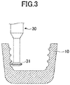
- the inner surface of the crown 10 is formed by cutting the block, using a cutting tool (see FIG. 3 ) having a disk-shaped rotatable working part 31 at its tip. This makes it possible to control the depth d from the cement space C, the width, the pitch, and the cross-sectional shape of the grooves 11a.
- Materials of the block which are not limited in particular, include a cured resin, a ceramic sintered body, and a metal.
- the crown 10 is made by curing a photocurable resin by exposing the photocurable resin to laser light thin section by thin section using a stereolithography apparatus.
- the crown 10 may be manufactured using a lost wax process.
- the crown 10 is put on the abutment tooth A, and it is determined whether the crown 10 fits.
- the shape of the outer surface and the shape of the inner surface of the crown 10 can be easily adapted by slightly cutting and grinding unfit parts.
- a dental cement is applied to the cement space C, and the crown 10 is thereafter put on and fixed to the abutment tooth A.
- bridges, etc. may be used as other dental prostheses to cover abutment teeth than crowns.
Landscapes
- Health & Medical Sciences (AREA)
- Epidemiology (AREA)
- Oral & Maxillofacial Surgery (AREA)
- Dentistry (AREA)
- Life Sciences & Earth Sciences (AREA)
- Animal Behavior & Ethology (AREA)
- General Health & Medical Sciences (AREA)
- Public Health (AREA)
- Veterinary Medicine (AREA)
- Ceramic Engineering (AREA)
- Engineering & Computer Science (AREA)
- Chemical & Material Sciences (AREA)
- Dental Prosthetics (AREA)
- Dental Tools And Instruments Or Auxiliary Dental Instruments (AREA)
Abstract
Description
- The present invention relates to dental prostheses.
- In general, dental prostheses such as crowns and bridges are fixed to abutment teeth through dental cement. Therefore, it is necessary to form a cement space between an abutment tooth and the inner surface of a dental prosthesis facing the abutment tooth.
- In recent years, CAD/CAM systems and CAD systems have drawn attention.
- CAD/CAM systems design a dental prosthesis using a computer, and thereafter make the dental prosthesis by cutting and grinding a block based on design data, using an automatic cutting and grinding machine. (See, for example, Patent Document 1.)
- Here, as a material constituting the block, cured resin, a ceramic sintered body, a metal or the like is known.
- Furthermore, CAD systems design a dental prosthesis using a computer, and thereafter make the dental prosthesis by curing a photocurable resin by exposing the photocurable resin to laser light thin section by thin section based on design data, using a stereolithography apparatus.
- According to CAD/CAM systems and CAD systems, first, the impression of an intraoral shape of a patient, such as a tooth shape or a dentition, is taken using a dental impression material, and thereafter, a plaster model is made. Next, the three-dimensional coordinate information of the plaster model is measured using a three-dimensional coordinate measuring apparatus. Furthermore, a dental prosthesis is designed based on the three-dimensional coordinate information of the plaster model using a computer. At this point, the operation of designing the margin line of the dental prosthesis, the operation of designing the internal shape of the dental prosthesis by adding a thickness commensurate with a cement space to the plaster model, and the operation of designing the external shape of the dental prosthesis to be exposed in an oral cavity are performed on the plaster model.
- In the case of using a CAD/CAM system, the dental prosthesis is made by selecting a material for a block to be processed, cutting and grinding the block using an automatic cutting and grinding machine, and thereafter trimming the block.
- In the case of using a CAD system, the dental prosthesis is made by curing a photocurable resin by exposing the photocurable resin to laser light thin section by thin section, using a stereolithography apparatus.
- Patent Document 1: Japanese Laid-open Patent Publication No.
2002-224142 - It is desired, however, to prevent removal of a dental prosthesis from an abutment tooth.
- Here, it is known to roughen the inner surface of a dental prosthesis to cover an abutment tooth by sand blasting, but this method cannot satisfactorily prevent removal of the dental prosthesis from the abutment tooth.
- An embodiment of the present invention has an object of providing a dental prosthesis that can prevent removal from an abutment tooth.
- An embodiment of the present invention is a dental prosthesis to cover an abutment tooth, which includes a groove formed in an inner side surface, wherein the depth of the groove from a cement space is 20 to 120 µm.
- According to an embodiment of the present invention, it is possible to provide a dental prosthesis that can prevent removal from an abutment tooth.
-
-
FIG. 1 is a diagram illustrating a dental prosthesis according to this embodiment. -
FIG. 2 is a diagram illustrating an example of a three-dimensional coordinate measuring apparatus used for the manufacture of the dental prosthesis ofFIG. 1 . -
FIG. 3 is a diagram illustrating an example of a tool used in forming an inner surface of the dental prosthesis ofFIG. 1 . - Next, an embodiment of the present invention is described.
-
FIG. 1 illustrates acrown 10 as an example of a dental prosthesis according to this embodiment. - The
crown 10 is exposed in an oral cavity, and includes an outer surface forming the shape of a tooth and an inner surface shaping a hollow to cover an abutment tooth A. - Here, a cement space C is formed between the inner surface of the
crown 10 and the abutment tooth A. -
Grooves 11a are continuously formed in aninner side surface 11 of thecrown 10 in its circumferential direction. - A depth d of the
grooves 11a from the cement space C is 20 to 120 µm, and is preferably 50 to 100 µm. When the depth d of thegrooves 11a from the cement space C is less than 20 µm, it is difficult to prevent removal of thecrown 10 from the abutment tooth A. The depth d in excess of 120 µm does not improve the effect of preventing removal of thecrown 10 from the abutment tooth A. - In the specification and the claims, the depth d of the
grooves 11a from the cement space C means a distance between the bottom surface of thegrooves 11a and the cement space C in a region where thegrooves 11a are not formed, namely, the cement space C in the case of assuming that thegrooves 11a are not formed. - The width of the
grooves 11a is preferably 240 to 330 µm. - The pitch of the
grooves 11a is preferably 280 to 380 µm. - Cross-sectional shapes of the
grooves 11a, which are not limited in particular as long as it is possible to prevent removal from the abutment tooth A, include a rectangular shape, a trapezoidal shape, a semi-circular shape, and a semi-elliptical shape, of which two or more may be used together. - The maximum thickness of the cement space C is preferably 15 to 120 µm.
- The
grooves 11a may be intermittently formed in theinner side surface 11 in its circumferential direction. - The
grooves 11a may be helically formed in theinner side surface 11. In this case, thegrooves 11a may be formed either continuously or intermittently. - Next, a method of manufacturing the
crown 10 is described. - First, the impression of an intraoral shape of a patient, such as a tooth shape or a dentition, is taken using a dental impression material, and thereafter, a plaster model is made. Next, the three-dimensional coordinate information of the plaster model of the intraoral shape is measured using a three-dimensional coordinate measuring apparatus.
-
FIG. 2 illustrates an example of the three-dimensional coordinate measuring apparatus. - A three-dimensional
coordinate measuring apparatus 20 includes aturntable 21 with a rotating shaft whose shaft center defines the Z-axis, an XY table 22 placed on theturntable 21 and movable along the X-axis and the Y-axis, and a placement table 23 fixed onto the XY table 22. A measurementobject attachment mount 24 to which a measurement object M is attachable may be placed on the placement table 23. - The three-dimensional
coordinate measuring apparatus 20 further includes a three-dimensionalcoordinate measuring part 25 that measures the three-dimensional coordinates of the measurement object M with alaser sensor 25a that can pivot about a desired point on the Z-axis in the same plane including the Z-axis and move along the Z-axis. - Next, a method of measuring the three-dimensional coordinates of the measurement object M using the three-dimensional
coordinate measuring apparatus 20 is described. - First, the measurement object M is attached to the measurement
object attachment mount 24, and the measurementobject attachment mount 24 is thereafter placed on the placement table 23. Next, the measurement object M is exposed to laser light by pivoting thelaser sensor 25a while rotating theturntable 21, thereby measuring the three-dimensional coordinates of the measurement object M. - Next, the
crown 10 is designed based on the three-dimensional coordinate information of the plaster model of an intraoral shape. For example, thecrown 10 is designed by deforming the visible outline of the margin line of thecrown 10 based on the plaster model of the intraoral shape graphically displayed three-dimensionally on the CRT display of a computer such that the margin line of thecrown 10 coincides with the margin line of the abutment tooth A. Furthermore, the shape of the inner surface of thecrown 10 facing the abutment tooth A is designed by adding a thickness commensurate with the cement space C to the plaster model of the intraoral shape. In addition, the shape of the outer surface of thecrown 10 to be exposed in the oral cavity is designed based on the three-dimensional graphics of a dentition on the abutment tooth A side and a dentition on the antagonist tooth side. - In the above-described manner, the designing of the
crown 10 is completed. - For example, in the case of using a CAD/CAM system, a block is cut and ground using a cutting and grinding machine and is thereafter trimmed, so that the outer surface and the inner surface of the
crown 10 are formed. At this point, for example, the inner surface of thecrown 10 is formed by cutting the block, using a cutting tool (seeFIG. 3 ) having a disk-shaped rotatable workingpart 31 at its tip. This makes it possible to control the depth d from the cement space C, the width, the pitch, and the cross-sectional shape of thegrooves 11a. - Materials of the block, which are not limited in particular, include a cured resin, a ceramic sintered body, and a metal.
- In the case of using a CAD system, the
crown 10 is made by curing a photocurable resin by exposing the photocurable resin to laser light thin section by thin section using a stereolithography apparatus. - The
crown 10 may be manufactured using a lost wax process. - Next, a method of fixing the
crown 10 to the abutment tooth A. - First, the
crown 10 is put on the abutment tooth A, and it is determined whether thecrown 10 fits. When thecrown 10 does not fit, the shape of the outer surface and the shape of the inner surface of thecrown 10 can be easily adapted by slightly cutting and grinding unfit parts. When thecrown 10 fits, a dental cement is applied to the cement space C, and thecrown 10 is thereafter put on and fixed to the abutment tooth A. - According to this embodiment, bridges, etc., may be used as other dental prostheses to cover abutment teeth than crowns.
- The present international application is based on and claims priority to Japanese patent application No.
2016-131020, filed on June 30, 2016 -
- 10 crown
- 11 inner side surface
- 11a groove
- A abutment tooth
- C cement space
- 20 three-dimensional coordinate measuring apparatus
- 21 turntable
- 22 XY table
- 23 placement table
- 24 measurement object attachment mount
- 25 three-dimensional coordinate measuring part
- 25a laser sensor
- M measurement object
- 30 cutting tool
- 31 working part
Claims (2)
- A dental prosthesis to cover an abutment tooth, the dental prosthesis comprising:a groove formed in an inner side surface,wherein a depth of the groove from a cement space is 20 to 120 µm.
- The dental prosthesis as claimed in claim 1, wherein the groove is formed in a circumferential direction of the inner side surface.
Applications Claiming Priority (2)
| Application Number | Priority Date | Filing Date | Title |
|---|---|---|---|
| JP2016131020 | 2016-06-30 | ||
| PCT/JP2017/017179 WO2018003286A1 (en) | 2016-06-30 | 2017-05-01 | Dental prosthesis |
Publications (2)
| Publication Number | Publication Date |
|---|---|
| EP3479794A1 true EP3479794A1 (en) | 2019-05-08 |
| EP3479794A4 EP3479794A4 (en) | 2020-02-19 |
Family
ID=60786031
Family Applications (1)
| Application Number | Title | Priority Date | Filing Date |
|---|---|---|---|
| EP17819653.1A Withdrawn EP3479794A4 (en) | 2016-06-30 | 2017-05-01 | Dental prosthesis |
Country Status (7)
| Country | Link |
|---|---|
| US (1) | US20190307536A1 (en) |
| EP (1) | EP3479794A4 (en) |
| JP (1) | JPWO2018003286A1 (en) |
| KR (1) | KR20190011758A (en) |
| CN (1) | CN109328041A (en) |
| AU (1) | AU2017290344A1 (en) |
| WO (1) | WO2018003286A1 (en) |
Families Citing this family (1)
| Publication number | Priority date | Publication date | Assignee | Title |
|---|---|---|---|---|
| KR20250066639A (en) * | 2023-11-07 | 2025-05-14 | 주식회사 바이오세텍 | Artificial crown and method for manufacturing the same |
Family Cites Families (14)
| Publication number | Priority date | Publication date | Assignee | Title |
|---|---|---|---|---|
| JPH11217239A (en) * | 1998-01-28 | 1999-08-10 | Lion Corp | Surface treated crystallized glass |
| WO2005115270A1 (en) * | 2004-05-28 | 2005-12-08 | Brain Base Corporation | Prosthesis fixing structure and prosthesis fixing method |
| JP2007215763A (en) * | 2006-02-16 | 2007-08-30 | Gc Corp | Dental prosthesis, its design method and its production method |
| US9801697B2 (en) * | 2011-03-18 | 2017-10-31 | Natural Dental Implants Ag | Integrated support device for providing temporary primary stability to dental implants and prosthesis, and related methods |
| US20100028835A1 (en) * | 2007-08-15 | 2010-02-04 | Hansen John P | Pedodontic/veterinary dental crown system |
| US9655690B2 (en) * | 2007-08-15 | 2017-05-23 | Ez Pedo, Inc. | Pedodontic/veterinary dental crown system |
| EP2289462B1 (en) * | 2009-08-25 | 2012-05-30 | BEGO Medical GmbH | Device and method for continuous generative production |
| WO2012134449A1 (en) * | 2011-03-29 | 2012-10-04 | Tuff Kid Crowns Llc | Pediatric and veterinary pre-made dental crowns |
| US20130081271A1 (en) * | 2011-10-04 | 2013-04-04 | F-Cube, Ltd. | Method of Making Self-Ligating Orthodontic Brackets and Component Parts |
| EP2742908B1 (en) * | 2012-12-12 | 2018-05-30 | Ivoclar Vivadent AG | Tooth with a recess in its base face |
| WO2014099761A1 (en) * | 2012-12-17 | 2014-06-26 | Global Filtration Systems, A Dba Of Gulf Filtration Systems Inc. | Dental arch model and method of making the same |
| CA2937969C (en) * | 2013-12-31 | 2023-10-03 | Dentsply International Inc. | Dental compositions containing upconversion phosphors and methods of use |
| US10136967B2 (en) * | 2016-03-09 | 2018-11-27 | Bicon, Llc | Dental implant abutment copings |
| US10278794B1 (en) * | 2018-09-28 | 2019-05-07 | 3D Med Ag | Systems and methods for making orthodontic brackets |
-
2017
- 2017-05-01 CN CN201780039460.7A patent/CN109328041A/en active Pending
- 2017-05-01 EP EP17819653.1A patent/EP3479794A4/en not_active Withdrawn
- 2017-05-01 KR KR1020187037144A patent/KR20190011758A/en not_active Ceased
- 2017-05-01 US US16/308,969 patent/US20190307536A1/en not_active Abandoned
- 2017-05-01 WO PCT/JP2017/017179 patent/WO2018003286A1/en not_active Ceased
- 2017-05-01 JP JP2018524927A patent/JPWO2018003286A1/en active Pending
- 2017-05-01 AU AU2017290344A patent/AU2017290344A1/en not_active Abandoned
Also Published As
| Publication number | Publication date |
|---|---|
| US20190307536A1 (en) | 2019-10-10 |
| KR20190011758A (en) | 2019-02-07 |
| WO2018003286A1 (en) | 2018-01-04 |
| CN109328041A (en) | 2019-02-12 |
| AU2017290344A1 (en) | 2019-01-17 |
| EP3479794A4 (en) | 2020-02-19 |
| JPWO2018003286A1 (en) | 2019-04-04 |
Similar Documents
| Publication | Publication Date | Title |
|---|---|---|
| EP1820466A1 (en) | Dental prosthesis, designing method thereof, and production method thereof | |
| EP1940310B1 (en) | Methods for manufacturing dental implant components | |
| US5128870A (en) | Automated high-precision fabrication of objects of complex and unique geometry | |
| US5184306A (en) | Automated high-precision fabrication of objects of complex and unique geometry | |
| AU2010209671B2 (en) | Method for producing a dentist tool | |
| US20140026419A1 (en) | Surgical guide fabrication | |
| EP1997453A2 (en) | Method for manufacturing digitally-designed removable dental prostheses and system required for this purpose | |
| JP2019535486A (en) | Three-dimensional orthodontic retention device and manufacturing method of three-dimensional orthodontic retention device | |
| CN106413624A (en) | Method for making semi-finished dental base | |
| JP4291897B2 (en) | Method for producing dental prosthesis | |
| US20160008112A1 (en) | Method for Producing a Distortion-Free Dental Model, and Dental Model so Produced | |
| US20140162213A1 (en) | Surgical guide fabrication | |
| CN104116569A (en) | Computer fabrication of dental prosthetic | |
| JPH1058281A (en) | Measuring or machining system | |
| KR101273867B1 (en) | Manufacturing method of prosthesis for in-lay | |
| JPH10192305A (en) | Production of artificial adaptation material and its device | |
| US20190307536A1 (en) | Dental prosthesis | |
| JP4464485B2 (en) | Processing method of dental prosthesis | |
| JP5837522B2 (en) | Abutment design method and abutment manufacturing method | |
| EP1895471A1 (en) | Program to make of cutting data for inner face of dental prosthesis | |
| JP6434829B2 (en) | Dental cutting block and manufacturing method thereof | |
| JP3817744B2 (en) | Method for adjusting inner surface of dental prosthesis, method for manufacturing dental prosthesis, and apparatus for designing dental prosthesis | |
| CA3130948A1 (en) | Method for generating a cam dataset | |
| JP2003000617A (en) | Measurement method for producing dental prosthesis | |
| WO2020070925A1 (en) | Try-in denture, try-in denture production program, and denture production method |
Legal Events
| Date | Code | Title | Description |
|---|---|---|---|
| STAA | Information on the status of an ep patent application or granted ep patent |
Free format text: STATUS: THE INTERNATIONAL PUBLICATION HAS BEEN MADE |
|
| PUAI | Public reference made under article 153(3) epc to a published international application that has entered the european phase |
Free format text: ORIGINAL CODE: 0009012 |
|
| STAA | Information on the status of an ep patent application or granted ep patent |
Free format text: STATUS: REQUEST FOR EXAMINATION WAS MADE |
|
| 17P | Request for examination filed |
Effective date: 20190103 |
|
| AK | Designated contracting states |
Kind code of ref document: A1 Designated state(s): AL AT BE BG CH CY CZ DE DK EE ES FI FR GB GR HR HU IE IS IT LI LT LU LV MC MK MT NL NO PL PT RO RS SE SI SK SM TR |
|
| AX | Request for extension of the european patent |
Extension state: BA ME |
|
| DAV | Request for validation of the european patent (deleted) | ||
| DAX | Request for extension of the european patent (deleted) | ||
| A4 | Supplementary search report drawn up and despatched |
Effective date: 20200121 |
|
| RIC1 | Information provided on ipc code assigned before grant |
Ipc: A61C 13/083 20060101ALI20200115BHEP Ipc: A61C 13/00 20060101ALI20200115BHEP Ipc: A61C 5/70 20170101AFI20200115BHEP Ipc: A61C 13/087 20060101ALI20200115BHEP |
|
| STAA | Information on the status of an ep patent application or granted ep patent |
Free format text: STATUS: THE APPLICATION HAS BEEN WITHDRAWN |
|
| 18W | Application withdrawn |
Effective date: 20200220 |