EP3479467B1 - Methods and apparatus for controlling an electric motor - Google Patents
Methods and apparatus for controlling an electric motor Download PDFInfo
- Publication number
- EP3479467B1 EP3479467B1 EP17730895.4A EP17730895A EP3479467B1 EP 3479467 B1 EP3479467 B1 EP 3479467B1 EP 17730895 A EP17730895 A EP 17730895A EP 3479467 B1 EP3479467 B1 EP 3479467B1
- Authority
- EP
- European Patent Office
- Prior art keywords
- limit
- torque
- speed
- current
- link
- Prior art date
- Legal status (The legal status is an assumption and is not a legal conclusion. Google has not performed a legal analysis and makes no representation as to the accuracy of the status listed.)
- Active
Links
Images



Classifications
-
- H—ELECTRICITY
- H02—GENERATION; CONVERSION OR DISTRIBUTION OF ELECTRIC POWER
- H02P—CONTROL OR REGULATION OF ELECTRIC MOTORS, ELECTRIC GENERATORS OR DYNAMO-ELECTRIC CONVERTERS; CONTROLLING TRANSFORMERS, REACTORS OR CHOKE COILS
- H02P6/00—Arrangements for controlling synchronous motors or other dynamo-electric motors using electronic commutation dependent on the rotor position; Electronic commutators therefor
- H02P6/06—Arrangements for speed regulation of a single motor wherein the motor speed is measured and compared with a given physical value so as to adjust the motor speed
-
- H—ELECTRICITY
- H02—GENERATION; CONVERSION OR DISTRIBUTION OF ELECTRIC POWER
- H02P—CONTROL OR REGULATION OF ELECTRIC MOTORS, ELECTRIC GENERATORS OR DYNAMO-ELECTRIC CONVERTERS; CONTROLLING TRANSFORMERS, REACTORS OR CHOKE COILS
- H02P6/00—Arrangements for controlling synchronous motors or other dynamo-electric motors using electronic commutation dependent on the rotor position; Electronic commutators therefor
-
- B—PERFORMING OPERATIONS; TRANSPORTING
- B60—VEHICLES IN GENERAL
- B60L—PROPULSION OF ELECTRICALLY-PROPELLED VEHICLES; SUPPLYING ELECTRIC POWER FOR AUXILIARY EQUIPMENT OF ELECTRICALLY-PROPELLED VEHICLES; ELECTRODYNAMIC BRAKE SYSTEMS FOR VEHICLES IN GENERAL; MAGNETIC SUSPENSION OR LEVITATION FOR VEHICLES; MONITORING OPERATING VARIABLES OF ELECTRICALLY-PROPELLED VEHICLES; ELECTRIC SAFETY DEVICES FOR ELECTRICALLY-PROPELLED VEHICLES
- B60L15/00—Methods, circuits, or devices for controlling the traction-motor speed of electrically-propelled vehicles
- B60L15/02—Methods, circuits, or devices for controlling the traction-motor speed of electrically-propelled vehicles characterised by the form of the current used in the control circuit
- B60L15/04—Methods, circuits, or devices for controlling the traction-motor speed of electrically-propelled vehicles characterised by the form of the current used in the control circuit using DC
-
- B—PERFORMING OPERATIONS; TRANSPORTING
- B60—VEHICLES IN GENERAL
- B60L—PROPULSION OF ELECTRICALLY-PROPELLED VEHICLES; SUPPLYING ELECTRIC POWER FOR AUXILIARY EQUIPMENT OF ELECTRICALLY-PROPELLED VEHICLES; ELECTRODYNAMIC BRAKE SYSTEMS FOR VEHICLES IN GENERAL; MAGNETIC SUSPENSION OR LEVITATION FOR VEHICLES; MONITORING OPERATING VARIABLES OF ELECTRICALLY-PROPELLED VEHICLES; ELECTRIC SAFETY DEVICES FOR ELECTRICALLY-PROPELLED VEHICLES
- B60L15/00—Methods, circuits, or devices for controlling the traction-motor speed of electrically-propelled vehicles
- B60L15/10—Methods, circuits, or devices for controlling the traction-motor speed of electrically-propelled vehicles for automatic control superimposed on human control to limit the acceleration of the vehicle, e.g. to prevent excessive motor current
-
- B—PERFORMING OPERATIONS; TRANSPORTING
- B60—VEHICLES IN GENERAL
- B60L—PROPULSION OF ELECTRICALLY-PROPELLED VEHICLES; SUPPLYING ELECTRIC POWER FOR AUXILIARY EQUIPMENT OF ELECTRICALLY-PROPELLED VEHICLES; ELECTRODYNAMIC BRAKE SYSTEMS FOR VEHICLES IN GENERAL; MAGNETIC SUSPENSION OR LEVITATION FOR VEHICLES; MONITORING OPERATING VARIABLES OF ELECTRICALLY-PROPELLED VEHICLES; ELECTRIC SAFETY DEVICES FOR ELECTRICALLY-PROPELLED VEHICLES
- B60L15/00—Methods, circuits, or devices for controlling the traction-motor speed of electrically-propelled vehicles
- B60L15/20—Methods, circuits, or devices for controlling the traction-motor speed of electrically-propelled vehicles for control of the vehicle or its driving motor to achieve a desired performance, e.g. speed, torque, programmed variation of speed
- B60L15/2072—Methods, circuits, or devices for controlling the traction-motor speed of electrically-propelled vehicles for control of the vehicle or its driving motor to achieve a desired performance, e.g. speed, torque, programmed variation of speed for drive off
- B60L15/2081—Methods, circuits, or devices for controlling the traction-motor speed of electrically-propelled vehicles for control of the vehicle or its driving motor to achieve a desired performance, e.g. speed, torque, programmed variation of speed for drive off for drive off on a slope
-
- B—PERFORMING OPERATIONS; TRANSPORTING
- B60—VEHICLES IN GENERAL
- B60L—PROPULSION OF ELECTRICALLY-PROPELLED VEHICLES; SUPPLYING ELECTRIC POWER FOR AUXILIARY EQUIPMENT OF ELECTRICALLY-PROPELLED VEHICLES; ELECTRODYNAMIC BRAKE SYSTEMS FOR VEHICLES IN GENERAL; MAGNETIC SUSPENSION OR LEVITATION FOR VEHICLES; MONITORING OPERATING VARIABLES OF ELECTRICALLY-PROPELLED VEHICLES; ELECTRIC SAFETY DEVICES FOR ELECTRICALLY-PROPELLED VEHICLES
- B60L3/00—Electric devices on electrically-propelled vehicles for safety purposes; Monitoring operating variables, e.g. speed, deceleration or energy consumption
- B60L3/06—Limiting the traction current under mechanical overload conditions
-
- H—ELECTRICITY
- H02—GENERATION; CONVERSION OR DISTRIBUTION OF ELECTRIC POWER
- H02P—CONTROL OR REGULATION OF ELECTRIC MOTORS, ELECTRIC GENERATORS OR DYNAMO-ELECTRIC CONVERTERS; CONTROLLING TRANSFORMERS, REACTORS OR CHOKE COILS
- H02P23/00—Arrangements or methods for the control of AC motors characterised by a control method other than vector control
- H02P23/14—Estimation or adaptation of motor parameters, e.g. rotor time constant, flux, speed, current or voltage
-
- H—ELECTRICITY
- H02—GENERATION; CONVERSION OR DISTRIBUTION OF ELECTRIC POWER
- H02P—CONTROL OR REGULATION OF ELECTRIC MOTORS, ELECTRIC GENERATORS OR DYNAMO-ELECTRIC CONVERTERS; CONTROLLING TRANSFORMERS, REACTORS OR CHOKE COILS
- H02P27/00—Arrangements or methods for the control of AC motors characterised by the kind of supply voltage
- H02P27/04—Arrangements or methods for the control of AC motors characterised by the kind of supply voltage using variable-frequency supply voltage, e.g. inverter or converter supply voltage
- H02P27/06—Arrangements or methods for the control of AC motors characterised by the kind of supply voltage using variable-frequency supply voltage, e.g. inverter or converter supply voltage using DC to AC converters or inverters
-
- H—ELECTRICITY
- H02—GENERATION; CONVERSION OR DISTRIBUTION OF ELECTRIC POWER
- H02P—CONTROL OR REGULATION OF ELECTRIC MOTORS, ELECTRIC GENERATORS OR DYNAMO-ELECTRIC CONVERTERS; CONTROLLING TRANSFORMERS, REACTORS OR CHOKE COILS
- H02P29/00—Arrangements for regulating or controlling electric motors, appropriate for both AC and DC motors
- H02P29/02—Providing protection against overload without automatic interruption of supply
- H02P29/024—Detecting a fault condition, e.g. short circuit, locked rotor, open circuit or loss of load
- H02P29/027—Detecting a fault condition, e.g. short circuit, locked rotor, open circuit or loss of load the fault being an over-current
-
- H—ELECTRICITY
- H02—GENERATION; CONVERSION OR DISTRIBUTION OF ELECTRIC POWER
- H02P—CONTROL OR REGULATION OF ELECTRIC MOTORS, ELECTRIC GENERATORS OR DYNAMO-ELECTRIC CONVERTERS; CONTROLLING TRANSFORMERS, REACTORS OR CHOKE COILS
- H02P29/00—Arrangements for regulating or controlling electric motors, appropriate for both AC and DC motors
- H02P29/02—Providing protection against overload without automatic interruption of supply
- H02P29/032—Preventing damage to the motor, e.g. setting individual current limits for different drive conditions
-
- B—PERFORMING OPERATIONS; TRANSPORTING
- B60—VEHICLES IN GENERAL
- B60L—PROPULSION OF ELECTRICALLY-PROPELLED VEHICLES; SUPPLYING ELECTRIC POWER FOR AUXILIARY EQUIPMENT OF ELECTRICALLY-PROPELLED VEHICLES; ELECTRODYNAMIC BRAKE SYSTEMS FOR VEHICLES IN GENERAL; MAGNETIC SUSPENSION OR LEVITATION FOR VEHICLES; MONITORING OPERATING VARIABLES OF ELECTRICALLY-PROPELLED VEHICLES; ELECTRIC SAFETY DEVICES FOR ELECTRICALLY-PROPELLED VEHICLES
- B60L2240/00—Control parameters of input or output; Target parameters
- B60L2240/40—Drive Train control parameters
- B60L2240/42—Drive Train control parameters related to electric machines
- B60L2240/421—Speed
-
- B—PERFORMING OPERATIONS; TRANSPORTING
- B60—VEHICLES IN GENERAL
- B60L—PROPULSION OF ELECTRICALLY-PROPELLED VEHICLES; SUPPLYING ELECTRIC POWER FOR AUXILIARY EQUIPMENT OF ELECTRICALLY-PROPELLED VEHICLES; ELECTRODYNAMIC BRAKE SYSTEMS FOR VEHICLES IN GENERAL; MAGNETIC SUSPENSION OR LEVITATION FOR VEHICLES; MONITORING OPERATING VARIABLES OF ELECTRICALLY-PROPELLED VEHICLES; ELECTRIC SAFETY DEVICES FOR ELECTRICALLY-PROPELLED VEHICLES
- B60L2240/00—Control parameters of input or output; Target parameters
- B60L2240/40—Drive Train control parameters
- B60L2240/42—Drive Train control parameters related to electric machines
- B60L2240/423—Torque
-
- B—PERFORMING OPERATIONS; TRANSPORTING
- B60—VEHICLES IN GENERAL
- B60L—PROPULSION OF ELECTRICALLY-PROPELLED VEHICLES; SUPPLYING ELECTRIC POWER FOR AUXILIARY EQUIPMENT OF ELECTRICALLY-PROPELLED VEHICLES; ELECTRODYNAMIC BRAKE SYSTEMS FOR VEHICLES IN GENERAL; MAGNETIC SUSPENSION OR LEVITATION FOR VEHICLES; MONITORING OPERATING VARIABLES OF ELECTRICALLY-PROPELLED VEHICLES; ELECTRIC SAFETY DEVICES FOR ELECTRICALLY-PROPELLED VEHICLES
- B60L2240/00—Control parameters of input or output; Target parameters
- B60L2240/40—Drive Train control parameters
- B60L2240/42—Drive Train control parameters related to electric machines
- B60L2240/425—Temperature
-
- B—PERFORMING OPERATIONS; TRANSPORTING
- B60—VEHICLES IN GENERAL
- B60L—PROPULSION OF ELECTRICALLY-PROPELLED VEHICLES; SUPPLYING ELECTRIC POWER FOR AUXILIARY EQUIPMENT OF ELECTRICALLY-PROPELLED VEHICLES; ELECTRODYNAMIC BRAKE SYSTEMS FOR VEHICLES IN GENERAL; MAGNETIC SUSPENSION OR LEVITATION FOR VEHICLES; MONITORING OPERATING VARIABLES OF ELECTRICALLY-PROPELLED VEHICLES; ELECTRIC SAFETY DEVICES FOR ELECTRICALLY-PROPELLED VEHICLES
- B60L2240/00—Control parameters of input or output; Target parameters
- B60L2240/40—Drive Train control parameters
- B60L2240/42—Drive Train control parameters related to electric machines
- B60L2240/427—Voltage
-
- B—PERFORMING OPERATIONS; TRANSPORTING
- B60—VEHICLES IN GENERAL
- B60L—PROPULSION OF ELECTRICALLY-PROPELLED VEHICLES; SUPPLYING ELECTRIC POWER FOR AUXILIARY EQUIPMENT OF ELECTRICALLY-PROPELLED VEHICLES; ELECTRODYNAMIC BRAKE SYSTEMS FOR VEHICLES IN GENERAL; MAGNETIC SUSPENSION OR LEVITATION FOR VEHICLES; MONITORING OPERATING VARIABLES OF ELECTRICALLY-PROPELLED VEHICLES; ELECTRIC SAFETY DEVICES FOR ELECTRICALLY-PROPELLED VEHICLES
- B60L2240/00—Control parameters of input or output; Target parameters
- B60L2240/40—Drive Train control parameters
- B60L2240/42—Drive Train control parameters related to electric machines
- B60L2240/429—Current
-
- Y—GENERAL TAGGING OF NEW TECHNOLOGICAL DEVELOPMENTS; GENERAL TAGGING OF CROSS-SECTIONAL TECHNOLOGIES SPANNING OVER SEVERAL SECTIONS OF THE IPC; TECHNICAL SUBJECTS COVERED BY FORMER USPC CROSS-REFERENCE ART COLLECTIONS [XRACs] AND DIGESTS
- Y02—TECHNOLOGIES OR APPLICATIONS FOR MITIGATION OR ADAPTATION AGAINST CLIMATE CHANGE
- Y02T—CLIMATE CHANGE MITIGATION TECHNOLOGIES RELATED TO TRANSPORTATION
- Y02T10/00—Road transport of goods or passengers
- Y02T10/60—Other road transportation technologies with climate change mitigation effect
- Y02T10/72—Electric energy management in electromobility
Definitions
- the present disclosure relates to methods and apparatus for controlling an electric motor.
- Electric motors may be controlled using a vehicle control unit sending instructions to a motor controller.
- the motor controller may comprise a motor control algorithm to control operation of the electric motor via an inverter coupled to a power supply.
- the output of the motor controller may be based on the instructions received from the vehicle control unit.
- current operating conditions may affect how the electric motor responds to these instructions. How the electric motor responds to the instructions may affect how resources are used and/or affect drive feel, and if not managed carefully may lead to damage of the motor, the motor controller and/or the power supply. For example, if the current drawn by the electric motor is too high the electric motor, the motor controller and/or the power supply may be damaged.
- US 2012/221183 A1 describes a method and controller for controlling a vehicle DC bus voltage by generating a parameter based on a reference DC bus voltage squared.
- Embodiments of the disclosure relate to a method and apparatus for controlling an electric motor, for example an AC electric motor powered by a DC power supply, for example from a battery.
- the disclosure relates to a method and apparatus for controlling an electric motor by controlling a torque demand sent to the electric motor.
- the torque demand may be controlled by a controller.
- the controller's job is to follow an input torque demand without exceeding limits for speed, torque, DC link current, DC link voltage, as well as optionally acceleration, jerk, backlash and thermal limits.
- the method may comprise setting a current limit, a speed limit and a torque limit, sensing a DC link current, comparing the sensed DC link current with the current limit, and adjusting the torque limit based on the comparison with the current limit to provide an adjusted torque limit.
- the method further comprises sensing the speed of the electric motor, comparing the speed with the speed limit and further adjusting the adjusted torque limit based on the comparison with the speed limit.
- the method may comprise setting a limit of the DC link current based on sensing the DC link voltage, and adjusting this current limit based on a comparison of the voltage with the voltage limit, setting a torque limit based on sensing: (a) the DC link current and (b) the speed, and adjusting the torque limit based on (a) a comparison of the DC link current with the current limit, and (b) a comparison of the speed with the speed limit.
- FIG. 1 Another aspect of the disclosure relates to an apparatus for controlling the torque demand sent to an electric motor.
- An example apparatus is shown in Figure 1 .
- the apparatus comprises a first input configured to receive at least one electrical limit corresponding to an electrical parameter of a DC link electrical supply, a second input configured to receive at least one mechanical limit corresponding to a mechanical parameter of the electric motor, and a controller configured to sense the DC link electrical supply for the at least one electrical parameter and adjust the mechanical limit based on a comparison with the electrical limit for that sensed electrical parameter.
- the controller is configured to receive a torque demand and adjust the torque demand based on a comparison with the adjusted mechanical limit.
- the example apparatus shown in Figure 1 comprises a controller 100.
- the controller 100 comprises at least two inputs coupled to a demand generator 200, for example a vehicle control unit, VCU.
- the controller 100 is also coupled to a battery management system, BMS.
- BMS battery management system
- the controller 100 is also coupled to a motor controller 300, which in turn is coupled to an electric motor 400.
- the motor controller 300 may be coupled to a power source, such as a battery, via a DC link.
- the motor controller 300 may comprise a motor control algorithm configured to control the electric motor based on the torque request it receives from the controller 100.
- the motor controller 300 also comprises an inverter coupled to the DC link.
- the motor control algorithm is configured to receive torque request instructions (for example, a torque set-point) from the controller 100 and control currents in the electric motor 400 via operation of the inverter.
- the at least two inputs are configured to receive signals from the demand generator 200.
- the signals comprise at least one limit of an electrical or mechanical parameter.
- the first input is configured to receive at least one electrical limit corresponding to an electrical parameter of a DC link electrical supply.
- the second input is configured to receive at least one mechanical limit corresponding to a mechanical parameter of the electric motor.
- the controller 100 is configured to sense the DC link electrical supply for the at least one electrical parameter and adjust the mechanical limit based on a comparison with the electrical limit for that sensed electrical parameter.
- the controller is also configured to receive a torque demand and adjust the torque demand based on a comparison with the adjusted mechanical limit.
- the first input actually comprises two inputs, a voltage input 102 and a current input 104.
- the second input also actually comprises two inputs, a speed input 106 and a torque input 108.
- the first input is configured to receive two electrical parameters comprising two electrical limits, the two electrical limits comprising a DC link current limit and a DC link voltage limit.
- the second input is also configured to receive two mechanical limits, the two mechanical limits comprising a torque limit and a speed limit.
- the controller 100 is configured to sense the DC link voltage and adjust the DC link current limit based on a comparison of the DC link voltage with the DC link voltage limit to provide an adjusted DC link current limit.
- the controller 100 is configured to sense the DC link current and then adjust the torque limit based on a comparison of the DC link current with the adjusted DC link current limit.
- the 100 controller is configured to then sense the speed of the electric motor and further adjust the adjusted torque limit based on a comparison of the speed with the speed limit.
- the controller 100 is configured to receive a torque demand and adjust the torque demand based on a comparison with the adjusted torque limit.
- the controller is configured to adjust an electrical or mechanical limit if a sensed electrical or mechanical parameter hits its corresponding electrical or mechanical limit.
- the mechanical limit may be adjusted in response to the sensed electrical parameter hitting the corresponding electrical limit. Hitting a limit may comprise equalling or exceeding that limit.
- the controller 100 may be configured to adjust the DC link current limit in response to the sensed DC link voltage hitting the DC link voltage limit. In some examples the controller 100 is configured to adjust the torque limit in response to the sensed DC link current hitting the adjusted DC link current limit. In some examples the controller 100 is configured to adjust the adjusted torque limit in response to the sensed speed hitting the speed limit. In some examples the controller 100 is configured to adjust the torque demand in response to the torque demand hitting the adjusted torque limit.
- the electrical or mechanical limit may comprise a maximum and minimum limit. It will therefore be understood that adjusting a limit for a parameter may comprise adjusting a maximum or a minimum limit for that parameter, or adjusting both maximum and minimum limits for that parameter.
- the current input 104 receives two current limits:
- the voltage input 102 receives two voltage limits:
- the speed input receives two speed limits:
- the controller 100 may therefore receive 9 inputs from the demand generator 200. These inputs received from the demand generator 200 may be called STIV inputs, due to the fact that they may comprise speed, S, torque, T, current, I, and voltage, V, limits.
- the current 104 and voltage 102 inputs may relate to current and voltage supplied on a DC link to the electric motor controller 300. Additionally or alternatively, if the controller 100 is also coupled to a BMS, the controller 100 may be configured to receive electrical limits relating to an electrical parameter of the DC link electrical supply from the BMS, such as a voltage limit and/or a current limit.
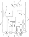
- the mechanical limits can be viewed on a speed-torque plane 320 and the electrical limits on a voltage-current plane 310, as shown in Figure 2 .
- the limits trace out a box in each plane.
- Eight STIV signals set the edges of the boxes.
- a ninth input received by the controller sets a desired torque (i.e. torque demand).
- the operating point X of the controller 100 is the present operating condition - the present DC link voltage 102c and current 104c in the electrical plane 310 and the present speed and torque in the mechanical plane 320. These operating points move as the electric motor operates.
- the motor is "motoring" in “forward” and is not close to any speed or torque limits
- the DC link is "discharging” and is not close to any I or V limits.
- the controller 100 will respect the STIV inputs and it is possible to create accurate and powerful systems with careful consideration to the STIV inputs.
- a relationship between speed and torque (i.e. power) for the motor 400 may be another input 110 to the controller 100.
- the relationship may be a speed-torque relationship at least partially characteristic of the electric motor 400.
- the controller may be configured to compare and adjust the torque demand with the speed-torque relationship so that the torque demand may be less than the torque according to the speed-torque relationship.
- the speed-torque relationship may put an upper limit on the maximum braking torque and maximum motoring torque and therefore the torque demand may be adjusted based on the speed-torque relationship.
- Temperature may be another input 112 into the controller 100.
- the controller 100 may be coupled to a temperature sensor.
- the controller 100 may be configured so that the torque limit is adjusted based on a received temperature signal.
- the controller 100 may be configured to provide thermal cutback from the temperature sensor.
- the maximum torque for example, one of the maximum motoring torque, the maximum braking torque, or the speed-torque curve
- the maximum motoring torque may be reduced as a function of increasing temperature.
- the controller 100 senses each of the parameters relating to each of the inputs 102, 104, 106, 108. When the operating point of one of these parameters hits the edge of one of the boxes shown in Figure 2 , the controller 100 adjusts the output torque request to keep the operating point inside the boxes.
- the electrical parameters may be prioritised over the mechanical parameters, so that the limits defined by the electrical box have priority.
- the torque limits may have priority, followed by the voltage limits, the current limits and the speed limits. This prioritisation of the limits may be inherent in the "cascade structure" of the controller 100, explained in more detail below and as shown in Figure 3 .
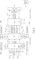
- the structure of the controller is shown in more detail in Figure 3 .
- the controller 100 uses a cascade structure where limits are respected by commanding the related physical value.
- the cascade structure comprises:
- the electrical regulator 120 comprises two regulators; a voltage regulator 152 and a current regulator 154.
- the voltage regulator 152 is coupled to voltage input 102 and current input 102.
- the current regulator 154 is coupled to the voltage regulator 152 and the torque input 108.
- the mechanical regulator 125 also comprises two regulators; a speed regulator 156 and an optional acceleration regulator 160.
- the mechanical regulator 125 is coupled to the speed input 106, the torque input 108 and to the current regulator 154. In some examples, the mechanical regulator 125 is further coupled to the optional torque rate of change regulator 162.
- Figure 4 shows a flowchart of the way that inputs feed into the regulators and how the inputs are processed by the regulators.
- the voltage regulator 152 is configured to receive a maximum DC link voltage limit 102a and a minimum DC link voltage limit 102b from voltage input 102. It is also configured to sense the DC link voltage 102c. The voltage regulator 152 is also configured to receive a maximum DC link discharging current 104a and a maximum DC link charging current 104b from current input 104. The voltage regulator 152 is configured to compare the sensed DC link voltage 102c with the voltage limits 102a, 102b and adjust the current limit based on the comparison with the voltage limits 102a, 102b. The voltage regulator 152 is configured to provide adjusted currents limits 104a, 104b to the current regulator 154.
- the current regulator 154 is configured to receive an input from the voltage regulator 152 comprising the adjusted current limits 104a, 104b, and also sense the DC link current 104c. The current regulator 154 is also configured to receive a maximum braking torque 108b and a maximum motoring torque 108a from torque input 108. The current regulator 154 is configured to compare the sensed DC link current 104c with the current limits 104a, 104b from the voltage regulator 152 and adjust the torque limits 108a, 108b based on the comparison with the current limits 104a, 104b. The current regulator is configured to provide adjusted torque limits 108a, 108b to the speed regulator 156.
- the speed regulator 156 is configured to receive an input from the current regulator 154 comprising the adjusted torque limits 108a, 108b.
- the speed regulator 156 is also configured to receive a motor maximum forward speed 106a, a motor maximum reverse speed 106b from the speed input 106, and also sense the current motor speed 106c.
- the speed regulator 156 is configured to compare the current speed 106c with the speed limits 106a, 106b and further adjust the adjusted torque limits 108a, 108b based on the comparison with the speed limit.
- the controller 100 is configured to sense a torque demand 108c received via the torque input 108 and compare the torque demand 108c with the adjusted torque limits 108a, 108b output by the speed regulator 156.
- the controller 100 is configured to adjust the torque demand 108c based on the comparison with the adjusted torque limits 108a, 108b, and output the adjusted torque demand 108c as a torque request to the electric motor controller 300.
- the voltage regulator 152 senses the DC link voltage 102c. When the voltage hits a voltage limit 102a, 102b, the voltage regulator 152 adjusts the DC link current limits 104a, 104b.
- the current regulator 154 senses the DC link current 104c. When the current 104c hits a current limit 104a, 104b, the current regulator 154 adjusts the torque limits 108a, 108b.
- the speed regulator 156 senses the motor speed 106c. When the speed 106c hits a speed limit 106a, 106b, the speed regulator 156 adjusts the torque limits 108a, 108b.
- the controller 100 senses a received torque demand 108c and adjusts the torque demand 108c based on a comparison with the adjusted torque limits 108a, 108b.
- another aspect of the disclosure relates to a method of controlling an electric motor 400.
- the method comprises setting a limit 104a, 104b of the DC link current 104c based on sensing the DC link voltage 102c, and adjusting this current limit 104a, 104b based on a comparison of the voltage 102c with the voltage limit 102a, 102b, setting a torque limit 108a, 108b based on sensing: (a) the DC link current 104c and (b) the speed 106c; and adjusting the torque limit 108a, 108b based on (a) a comparison of the DC link current 104c with the current limit 104a, 104b, and/or (b) a comparison of the speed 106c with the speed limit 106a, 106b.
- the controller 100 may control maximum acceleration and/or jerk when approaching one of the speed limits 106a, as shown in Figure 5 .
- a jerk limit may be considered a limit of the rate of change of acceleration.
- the controller 100 may comprise an acceleration regulator 160.
- the acceleration regulator 160 may be part of the mechanical regulator 125 and be coupled to the speed input 106.
- the acceleration regulator 160 may also be coupled to the speed regulator 156.
- the acceleration regulator 160 may have a known acceleration limit (for example the acceleration limit may have been pre-programmed) or may receive an acceleration limit via an input, for example from the demand generator 200.
- the acceleration regulator 160 may be configured to receive at least one speed limit 106a, 106b from the speed input 106, and compare the sensed speed 106c (and thereby acceleration and optionally rate of change of acceleration) with an acceleration limit and/or a rate of change of acceleration limit. Based on the comparison with the acceleration limit and/or the rate of change of acceleration limit, the acceleration regulator 160 may adjust the speed limits 160a, 106b to meet the acceleration limit and/or the rate of change of acceleration limit. For example, this may comprise adjusting the speed limits 106a, 106b over time so that the acceleration meets the acceleration limit, or adjusting the speed limits 106a, 106b over time so that the rate of change of acceleration meets the acceleration rate of change limit.
- the adjusted speed limits 106a, 106b provided by the acceleration regulator 160 may be used by the speed regulator 156.
- the speed regulator 156 may compare the sensed speed 106c with the adjusted speed limits 106a, 106b (provided by the acceleration regulator 160) and adjust the torque limits 108a, 108b based on a comparison of the sensed speed 106c with the adjusted speed limits 106a, 106b.
- the acceleration regulator 160 may also be used for loss of traction (or load) situations, where the acceleration limit may be set somewhat larger than the acceleration which can be achieved by the motor 400 under normal conditions.
- the controller 100 may also comprise an optional torque rate of change regulator 162.
- the torque rate of change regulator 162 may have a torque rate of change limit, and may for example act as a backlash compensator.
- the torque rate of change limit may be pre-programmed into the torque rate of change regulator 162, or may be received by an input, for example from the demand generator 200.
- the electric motor 400 may be coupled to a drivetrain that, for example, connects it to wheels for traction.
- the drivetrain may have its own characteristics, and if instantaneous acceleration is too high, can result in the drivetrain unwinding.
- the torque rate of change regulator 162 may prevent the change in torque being greater than the drivetrain can manage (thus preventing resultant backlash).
- the torque rate of change regulator 162 may do this by sensing the torque demand 108c over time to determine the torque rate of change, and by comparing the torque rate of change with the torque rate of change limit. Based on the comparison with the torque rate of change limit the torque rate of change regulator may adjust the torque demand 108c.
- the torque rate of change regulator 162 may limit instantaneous acceleration, such as that which occurs when drivetrains unwind.
- the torque rate of change regulator 162 may be configured to prevent a quick change in torque through zero speed resulting in "clunk” due to gear lash.
- the torque rate of change regulator 162 may sense the speed 106c of the motor 400 and comprise a separate torque rate of change limit 108a, 108b when the speed passes through zero. This may be considered an "open loop" approach.
- the torque rate of change regulator 162 may have different torque rate of change limits for different operating speeds 106c or speed ranges.
- the torque rate of change regulator 162 uses sensed acceleration as a negative feedback to compensate the torque output. For example, typically drivetrain issues like windup and gear lash result in very fast accelerations for very short times. The negative feedback acceleration feedback may deal with this.
- the torque rate of change regulator 162 may be configured to sense acceleration (for example by sensing speed 106c over time) and adjust the torque demand 108c based on a comparison with the acceleration, for example the torque rate of change regulator 162 may be configured to adjust the torque demand based on an inverse relationship with sensed acceleration.
- temperature may be another input 112 into the controller 100.
- the controller 100 may comprise a thermal regulator.
- the thermal regulator may be configured to sense the current temperature and compare the current temperature to a temperature limit.
- the thermal regulator may be configured to adjust the torque limits 108a, 108b based on the comparison with the temperature limit, for example the thermal regulator may be configured to adjust the torque limits 108a, 108b in response to the sensed temperature hitting the temperature limit.
- the temperature limit may be pre-programmed or may be received via an input, for example from the demand generator 200.
- one or more of the regulators may be switched off, and the functionality of that regulator provided, for example, by a look up table or another element external to the controller 100.
- the controller 100 may be configured to receive an input from a BMS.
- the BMS may produce a maximum charge 102a and maximum discharge 102b current value based on a battery state of charge.
- the BMS may control the DC link voltage 102c and the controller voltage regulator 152 can be turned off.
- the current regulator 154 may be switched off.
- the current regulator 154 may be replaced by a look up table that reduces the current limits 102a, 102b as a function of voltage.
- the speed regulator 156 may be switched off and the torque limits 108a, 108b adjusted as a function of speed, for example according to a look up table.
- each regulator may be used to respect one limit for a parameter, or both the minimum and maximum limits for a parameter. It will be understood, however, that separate regulators may be used to respect the minimum and maximum limits.
- the voltage regulator may comprise a first voltage regulator to compare the sensed DC link voltage 102c with a voltage charge limit 102a and a second voltage regulator to compare the sensed DC link voltage 102c with a voltage charge limit 102b.
- the current regulator 154, acceleration regulator 160, speed regulator 156 and torque rate of change regulator may comprise respective first and second regulators.
- the torque request sent to the motor controller 300 will follow the torque demand 108c received by the controller 100 provided this respects the electrical and mechanical limits 102a, 102b, 104a, 104b, 106a, 106b, 108a, 108b, as indicated in Figure 2 .
- the operating point touches an edge (limit), and accordingly adjusts the output torque request, it touches only one of the edges and the edge is one of the STIV inputs.
- the controller 100 can report this via a "What's Active" property.
- the controller's "What's Active” property has a special format made up of two 16-bit values which can indicate which of the STIV inputs is being followed, as indicated in Table 1, above.
- the controller 100 there may be as many as 6 regulators or more. At any point in time the only active regulators are those involved in the "What's Active" path. Most of the regulators are “sensing and waiting” to make sure that a limit is respected; they are not actually doing anything and are “open loop". Each regulator uses several methods to be well-behaved while “sensing and waiting” including aggressive anti-windup techniques and limiting the output of any regulator to that which will be allowed by the output torque rate limit. In some examples the regulators may be prevented from winding up dynamically and/or statically.
- Statically means that the regulators won't windup past a selected limit. Dynamically means that they won't windup into the final torque rate limit during a fast change in operating point.
- the limits used by the regulators may track the operating point by an amount that is related to the out rate limit (for example, a percentage of the limit such as 90 %) so that the regulators may be prevented from winding up into their limits.
- Feedforward estimates what the output of a regulator should be for a desired input.
- the feedforwards may be used to bypass the regulators to speed up their response to quick changes in the sensed parameter.
- the feedforward for the voltage regulator 152 may be the DC link current feedback (which may be reduced slightly with a gain). The voltage regulator 152 may therefore only be used to make corrections to the operating point for that parameter.
- the feedforward for the current regulator 154 may be an estimate of the torque required to hit the current set-point from the voltage regulator 152. Feedforward does not need to be exact (for example, only 90% of the estimated output value may be used), but it may do much of the "heavy lifting" in the regulators and may improve response.
- the speed regulator 156 may also have a "high resolution" position feature to allow speed tracking for changing demands and for low speed "hill hold” operations.
- the high resolution position feature makes use of position feedback (of the electric motor) and it is a higher order regulator than the normal speed regulator.
- the high resolution position feature may have two primary advantages: it can track a ramp with zero steady state error, and it can truly hold zero speed since it regulates position. It provides a significant improvement in hill-hold situations.
- the high resolution speed regulator is used for accurate speed/position during hill-hold & roll-off. It may also provide more precise speed control in applications such as automated guided vehicles, AGV. While it can be used at all times, its more aggressive application of torque tends to feel unnatural.
- the use of the high resolution speed regulator is entirely configurable: it can always be used, never be used, or only used at lower speeds.
- the controller 100 may also comprise a torque rate regulator 158 coupled to the torque input 108 and the input to the current regulator 154.
- the torque rate regulator 158 may be configured to limit a rate of change in the torque limits 108a, 108b.
- the torque rate regulator 158 may be configured to sense the torque limits 108a, 108b and in response to the torque limits 108a, 108b changing, compare their rate of change with a rate of change limit or relationship (for example, the torque rate of change limit may be a function of speed or may depend on whether the torque relates to motoring torque or braking torque) and if necessary adjust the torque limits 108a, 108b to meet the stored torque rate of change limit.
- the torque rate regulator 158 may be configured to sense the torque demand 108c and in response to the torque demand 108c changing, compare its range of change with a rate of change limit or relationship (for example the rate of change limit may be a function of speed or depend on whether the torque relates to motoring torque or braking torque) and if necessary adjust the torque demand 108c to meet the torque rate of change limit. In this way, the torque rate regulator 158 may prevent step changes in the torque request on step changes in the inputs. Thus if a torque limit on STIV is reduced abruptly in such a way that the output torque request must be reduced, the torque is ramped down in a controlled manner. In some examples there is a ramp-up and ramp-down rate for motoring torque, and a ramp-up and ramp-down rate for braking torque.
- the controller 100 may also comprise an optional power regulator.
- the power regulator may be coupled to the torque input 108, and if present optionally operate in conjunction with the torque rate regulator 158.
- the power regulator may be configured to receive an adjusted torque demand 108c or adjusted torque limits 108a, 108b from the torque rate regulator 158.
- the power regulator may be configured to receive a relationship between speed and torque (i.e. power) for the motor 400, for example via input 110 to the controller 100.
- the relationship may be a speed-torque relationship at least partially characteristic of the electric motor 400.
- the power regulator may be configured to sense the torque demand 108c and compare and adjust the torque demand 108c with the speed-torque relationship so that the torque demand 108c may be less than the torque according to the speed-torque relationship.
- the adjusted torque demand 108c may then be fed into the electrical regulator 120, for example the current regulator 154.
- the speed-torque relationship may put an upper limit on the maximum braking torque 108b and maximum motoring torque 108a and therefore the torque demand 108c may be adjusted based on the speed-torque relationship.
- one or more memory elements can store data and/or program instructions used to implement the operations described herein.
- Embodiments of the disclosure provide tangible, non-transitory storage media comprising program instructions operable to program a processor to perform any one or more of the methods described and/or claimed herein and/or to provide data processing apparatus as described and/or claimed herein.
- programmable logic may be implemented with fixed logic such as assemblies of logic gates or programmable logic such as software and/or computer program instructions executed by a processor.
- Other kinds of programmable logic include programmable processors, programmable digital logic (e.g., a field programmable gate array (FPGA), an erasable programmable read only memory (EPROM), an electrically erasable programmable read only memory (EEPROM)), an application specific integrated circuit, ASIC, or any other kind of digital logic, software, code, electronic instructions, flash memory, optical disks, CD-ROMs, DVD ROMs, magnetic or optical cards, other types of machine-readable mediums suitable for storing electronic instructions, or any suitable combination thereof.
- FPGA field programmable gate array
- EPROM erasable programmable read only memory
- EEPROM electrically erasable programmable read only memory
- ASIC application specific integrated circuit
Landscapes
- Engineering & Computer Science (AREA)
- Power Engineering (AREA)
- Transportation (AREA)
- Mechanical Engineering (AREA)
- Life Sciences & Earth Sciences (AREA)
- Sustainable Development (AREA)
- Sustainable Energy (AREA)
- Electric Propulsion And Braking For Vehicles (AREA)
- Control Of Electric Motors In General (AREA)
Description
- The present disclosure relates to methods and apparatus for controlling an electric motor.
- Electric motors may be controlled using a vehicle control unit sending instructions to a motor controller. The motor controller may comprise a motor control algorithm to control operation of the electric motor via an inverter coupled to a power supply. The output of the motor controller may be based on the instructions received from the vehicle control unit. In use, current operating conditions may affect how the electric motor responds to these instructions. How the electric motor responds to the instructions may affect how resources are used and/or affect drive feel, and if not managed carefully may lead to damage of the motor, the motor controller and/or the power supply. For example, if the current drawn by the electric motor is too high the electric motor, the motor controller and/or the power supply may be damaged.
-
US 2012/221183 A1 describes a method and controller for controlling a vehicle DC bus voltage by generating a parameter based on a reference DC bus voltage squared. - Aspects of the invention are as set out in the independent claims and optional features are set out in the dependent claims. Aspects of the invention may be provided in conjunction with each other and features of one aspect may be applied to other aspects.
- Embodiments of the disclosure will now be described, by way of example only, with reference to the accompanying drawings, in which:
-
Figure 1 shows an overview schematic of an apparatus for controlling an electric motor; -
Figure 2 shows two graphs showing a range of limits acting on parameters of an electric motor, including limits acting on the DC link to the electric motor and mechanical limits of the electric motor; -
Figure 3 shows a schematic of elements of an apparatus for controlling the torque demand sent to an electric motor such as the apparatus shown inFigure 1 ; -
Figure 4 shows an example flow chart of a method for controlling an electric motor; and -
Figure 5 shows an example speed-time curve for an electric motor operating according to a method such as that shown inFigure 4 . - Embodiments of the disclosure relate to a method and apparatus for controlling an electric motor, for example an AC electric motor powered by a DC power supply, for example from a battery. In general, the disclosure relates to a method and apparatus for controlling an electric motor by controlling a torque demand sent to the electric motor. The torque demand may be controlled by a controller. The controller's job is to follow an input torque demand without exceeding limits for speed, torque, DC link current, DC link voltage, as well as optionally acceleration, jerk, backlash and thermal limits.
- In some aspects of the disclosure, the method may comprise setting a current limit, a speed limit and a torque limit, sensing a DC link current, comparing the sensed DC link current with the current limit, and adjusting the torque limit based on the comparison with the current limit to provide an adjusted torque limit. The method further comprises sensing the speed of the electric motor, comparing the speed with the speed limit and further adjusting the adjusted torque limit based on the comparison with the speed limit.
- In other aspects of the disclosure, the method may comprise setting a limit of the DC link current based on sensing the DC link voltage, and adjusting this current limit based on a comparison of the voltage with the voltage limit, setting a torque limit based on sensing: (a) the DC link current and (b) the speed, and adjusting the torque limit based on (a) a comparison of the DC link current with the current limit, and (b) a comparison of the speed with the speed limit.
- Another aspect of the disclosure relates to an apparatus for controlling the torque demand sent to an electric motor. An example apparatus is shown in
Figure 1 . The apparatus comprises a first input configured to receive at least one electrical limit corresponding to an electrical parameter of a DC link electrical supply, a second input configured to receive at least one mechanical limit corresponding to a mechanical parameter of the electric motor, and a controller configured to sense the DC link electrical supply for the at least one electrical parameter and adjust the mechanical limit based on a comparison with the electrical limit for that sensed electrical parameter. The controller is configured to receive a torque demand and adjust the torque demand based on a comparison with the adjusted mechanical limit. - The example apparatus shown in
Figure 1 comprises acontroller 100. Thecontroller 100 comprises at least two inputs coupled to ademand generator 200, for example a vehicle control unit, VCU. In some examples thecontroller 100 is also coupled to a battery management system, BMS. Thecontroller 100 is also coupled to amotor controller 300, which in turn is coupled to anelectric motor 400. Themotor controller 300 may be coupled to a power source, such as a battery, via a DC link. Themotor controller 300 may comprise a motor control algorithm configured to control the electric motor based on the torque request it receives from thecontroller 100. Themotor controller 300 also comprises an inverter coupled to the DC link. The motor control algorithm is configured to receive torque request instructions (for example, a torque set-point) from thecontroller 100 and control currents in theelectric motor 400 via operation of the inverter. - The at least two inputs are configured to receive signals from the
demand generator 200. The signals comprise at least one limit of an electrical or mechanical parameter. The first input is configured to receive at least one electrical limit corresponding to an electrical parameter of a DC link electrical supply. The second input is configured to receive at least one mechanical limit corresponding to a mechanical parameter of the electric motor. - The
controller 100 is configured to sense the DC link electrical supply for the at least one electrical parameter and adjust the mechanical limit based on a comparison with the electrical limit for that sensed electrical parameter. The controller is also configured to receive a torque demand and adjust the torque demand based on a comparison with the adjusted mechanical limit. - In the example shown in
Figures 1 ,3 and4 , the first input actually comprises two inputs, avoltage input 102 and acurrent input 104. The second input also actually comprises two inputs, aspeed input 106 and atorque input 108. The first input is configured to receive two electrical parameters comprising two electrical limits, the two electrical limits comprising a DC link current limit and a DC link voltage limit. The second input is also configured to receive two mechanical limits, the two mechanical limits comprising a torque limit and a speed limit. - The
controller 100 is configured to sense the DC link voltage and adjust the DC link current limit based on a comparison of the DC link voltage with the DC link voltage limit to provide an adjusted DC link current limit. Thecontroller 100 is configured to sense the DC link current and then adjust the torque limit based on a comparison of the DC link current with the adjusted DC link current limit. The 100 controller is configured to then sense the speed of the electric motor and further adjust the adjusted torque limit based on a comparison of the speed with the speed limit. Finally, thecontroller 100 is configured to receive a torque demand and adjust the torque demand based on a comparison with the adjusted torque limit. - In some examples, the controller is configured to adjust an electrical or mechanical limit if a sensed electrical or mechanical parameter hits its corresponding electrical or mechanical limit. For example, the mechanical limit may be adjusted in response to the sensed electrical parameter hitting the corresponding electrical limit. Hitting a limit may comprise equalling or exceeding that limit.
- For example, the
controller 100 may be configured to adjust the DC link current limit in response to the sensed DC link voltage hitting the DC link voltage limit. In some examples thecontroller 100 is configured to adjust the torque limit in response to the sensed DC link current hitting the adjusted DC link current limit. In some examples thecontroller 100 is configured to adjust the adjusted torque limit in response to the sensed speed hitting the speed limit. In some examples thecontroller 100 is configured to adjust the torque demand in response to the torque demand hitting the adjusted torque limit. - In some examples, the electrical or mechanical limit may comprise a maximum and minimum limit. It will therefore be understood that adjusting a limit for a parameter may comprise adjusting a maximum or a minimum limit for that parameter, or adjusting both maximum and minimum limits for that parameter.
- For example, in the example shown in
Figures 1 ,3 and4 , thecurrent input 104 receives two current limits: - ∘ Maximum DC
link discharging current 104a - ∘ Maximum DC link charging current 104b
- In the example shown in
Figures 1 ,3 and4 , thevoltage input 102 receives two voltage limits: - ∘ Maximum
DC Link voltage 102a - ∘ Minimum
DC Link voltage 102b - In the example shown in
Figures 1 ,3 and4 , the speed input receives two speed limits: - ∘ Maximum
forward speed 106a - ∘ Maximum
reverse speed 106b - In the example shown in
Figures 1 ,3 and4 , the torque input receives: - ∘
Torque demand 108c - ∘
Maximum motoring torque 108a - ∘
Maximum braking torque 108b - The
controller 100 may therefore receive 9 inputs from thedemand generator 200. These inputs received from thedemand generator 200 may be called STIV inputs, due to the fact that they may comprise speed, S, torque, T, current, I, and voltage, V, limits. The current 104 andvoltage 102 inputs may relate to current and voltage supplied on a DC link to theelectric motor controller 300. Additionally or alternatively, if thecontroller 100 is also coupled to a BMS, thecontroller 100 may be configured to receive electrical limits relating to an electrical parameter of the DC link electrical supply from the BMS, such as a voltage limit and/or a current limit. - The mechanical limits can be viewed on a speed-
torque plane 320 and the electrical limits on a voltage-current plane 310, as shown inFigure 2 . The limits trace out a box in each plane. Eight STIV signals set the edges of the boxes. A ninth input received by the controller sets a desired torque (i.e. torque demand). The operating point X of thecontroller 100 is the present operating condition - the presentDC link voltage 102c and current 104c in theelectrical plane 310 and the present speed and torque in themechanical plane 320. These operating points move as the electric motor operates. In this example shown inFigure 2 , at this point in time: the motor is "motoring" in "forward" and is not close to any speed or torque limits, and the DC link is "discharging" and is not close to any I or V limits. - With the STIV inputs, it is possible to create traction systems with hill-hold, generators with multistage charging profiles and hybrid systems. The
controller 100 will respect the STIV inputs and it is possible to create accurate and powerful systems with careful consideration to the STIV inputs. - A relationship between speed and torque (i.e. power) for the
motor 400 may be anotherinput 110 to thecontroller 100. The relationship may be a speed-torque relationship at least partially characteristic of theelectric motor 400. The controller may be configured to compare and adjust the torque demand with the speed-torque relationship so that the torque demand may be less than the torque according to the speed-torque relationship. In effect, the speed-torque relationship may put an upper limit on the maximum braking torque and maximum motoring torque and therefore the torque demand may be adjusted based on the speed-torque relationship. - Temperature may be another
input 112 into thecontroller 100. For example, thecontroller 100 may be coupled to a temperature sensor. Thecontroller 100 may be configured so that the torque limit is adjusted based on a received temperature signal. For example, thecontroller 100 may be configured to provide thermal cutback from the temperature sensor. For example, when either themotor 400 orcontroller 300 is hot, the maximum torque (for example, one of the maximum motoring torque, the maximum braking torque, or the speed-torque curve) may be reduced. For example, the maximum motoring torque may be reduced as a function of increasing temperature. - The
controller 100 senses each of the parameters relating to each of theinputs Figure 2 , thecontroller 100 adjusts the output torque request to keep the operating point inside the boxes. In some examples the electrical parameters may be prioritised over the mechanical parameters, so that the limits defined by the electrical box have priority. In some examples, the torque limits may have priority, followed by the voltage limits, the current limits and the speed limits. This prioritisation of the limits may be inherent in the "cascade structure" of thecontroller 100, explained in more detail below and as shown inFigure 3 . - The structure of the controller is shown in more detail in
Figure 3 . Thecontroller 100 uses a cascade structure where limits are respected by commanding the related physical value. The cascade structure comprises: - An E-reg (electrical regulator) 120 coupled to the first (electrical) input, configured to sense and respect the V and I limits (keep the operating point within the electrical box);
- An M-reg (mechanical regulator) 125 coupled to the second (mechanical) input, configured to sense and respect the S and T limits (keep the operating point within the mechanical box);
- An optional torque rate of
change regulator 162 acting as a backlash compensator configured to manage the drivetrain characteristics; - An optional thermal regulator configured to modify the output torque request based on a temperature (not shown);
- An optional power regulator (not shown);
- An
optional acceleration regulator 160; - An optional
torque rate regulator 158. - The
electrical regulator 120 comprises two regulators; avoltage regulator 152 and acurrent regulator 154. Thevoltage regulator 152 is coupled tovoltage input 102 andcurrent input 102. Thecurrent regulator 154 is coupled to thevoltage regulator 152 and thetorque input 108. Themechanical regulator 125 also comprises two regulators; aspeed regulator 156 and anoptional acceleration regulator 160. Themechanical regulator 125 is coupled to thespeed input 106, thetorque input 108 and to thecurrent regulator 154. In some examples, themechanical regulator 125 is further coupled to the optional torque rate ofchange regulator 162. -
Figure 4 shows a flowchart of the way that inputs feed into the regulators and how the inputs are processed by the regulators. - The
voltage regulator 152 is configured to receive a maximum DClink voltage limit 102a and a minimum DClink voltage limit 102b fromvoltage input 102. It is also configured to sense theDC link voltage 102c. Thevoltage regulator 152 is also configured to receive a maximum DC link discharging current 104a and a maximum DC link charging current 104b fromcurrent input 104. Thevoltage regulator 152 is configured to compare the sensedDC link voltage 102c with thevoltage limits voltage limits voltage regulator 152 is configured to provide adjustedcurrents limits current regulator 154. - The
current regulator 154 is configured to receive an input from thevoltage regulator 152 comprising the adjustedcurrent limits current regulator 154 is also configured to receive amaximum braking torque 108b and amaximum motoring torque 108a fromtorque input 108. Thecurrent regulator 154 is configured to compare the sensed DC link current 104c with thecurrent limits voltage regulator 152 and adjust thetorque limits current limits torque limits speed regulator 156. - The
speed regulator 156 is configured to receive an input from thecurrent regulator 154 comprising the adjustedtorque limits speed regulator 156 is also configured to receive a motor maximumforward speed 106a, a motor maximumreverse speed 106b from thespeed input 106, and also sense thecurrent motor speed 106c. Thespeed regulator 156 is configured to compare thecurrent speed 106c with thespeed limits torque limits - Otherwise, the
controller 100 is configured to sense atorque demand 108c received via thetorque input 108 and compare thetorque demand 108c with the adjustedtorque limits speed regulator 156. Thecontroller 100 is configured to adjust thetorque demand 108c based on the comparison with the adjustedtorque limits torque demand 108c as a torque request to theelectric motor controller 300. - In operation, the
voltage regulator 152 senses theDC link voltage 102c. When the voltage hits avoltage limit voltage regulator 152 adjusts the DC linkcurrent limits current regulator 154 senses the DC link current 104c. When the current 104c hits acurrent limit current regulator 154 adjusts thetorque limits speed regulator 156 senses themotor speed 106c. When thespeed 106c hits aspeed limit speed regulator 156 adjusts thetorque limits controller 100 senses a receivedtorque demand 108c and adjusts thetorque demand 108c based on a comparison with the adjustedtorque limits torque demand 108c may be output as a torque request to themotor controller 300. Therefore DClink voltage limits current limits current limits motor torque limits Motor speed limits motor torque limits - Accordingly, another aspect of the disclosure relates to a method of controlling an
electric motor 400. The method comprises setting alimit DC link voltage 102c, and adjusting thiscurrent limit voltage 102c with thevoltage limit torque limit speed 106c; and adjusting thetorque limit current limit speed 106c with thespeed limit - In some examples, the
controller 100 may control maximum acceleration and/or jerk when approaching one of thespeed limits 106a, as shown inFigure 5 . A jerk limit may be considered a limit of the rate of change of acceleration. Thecontroller 100 may comprise anacceleration regulator 160. Theacceleration regulator 160 may be part of themechanical regulator 125 and be coupled to thespeed input 106. Theacceleration regulator 160 may also be coupled to thespeed regulator 156. Theacceleration regulator 160 may have a known acceleration limit (for example the acceleration limit may have been pre-programmed) or may receive an acceleration limit via an input, for example from thedemand generator 200. - The
acceleration regulator 160 may be configured to receive at least onespeed limit speed input 106, and compare the sensedspeed 106c (and thereby acceleration and optionally rate of change of acceleration) with an acceleration limit and/or a rate of change of acceleration limit. Based on the comparison with the acceleration limit and/or the rate of change of acceleration limit, theacceleration regulator 160 may adjust thespeed limits 160a, 106b to meet the acceleration limit and/or the rate of change of acceleration limit. For example, this may comprise adjusting thespeed limits speed limits adjusted speed limits acceleration regulator 160 may be used by thespeed regulator 156. Thespeed regulator 156 may compare the sensedspeed 106c with theadjusted speed limits torque limits speed 106c with theadjusted speed limits - The
acceleration regulator 160 may also be used for loss of traction (or load) situations, where the acceleration limit may be set somewhat larger than the acceleration which can be achieved by themotor 400 under normal conditions. - The
controller 100 may also comprise an optional torque rate ofchange regulator 162. The torque rate ofchange regulator 162 may have a torque rate of change limit, and may for example act as a backlash compensator. As for the acceleration limit for theacceleration regulator 160, the torque rate of change limit may be pre-programmed into the torque rate ofchange regulator 162, or may be received by an input, for example from thedemand generator 200. Theelectric motor 400 may be coupled to a drivetrain that, for example, connects it to wheels for traction. The drivetrain may have its own characteristics, and if instantaneous acceleration is too high, can result in the drivetrain unwinding. - The torque rate of
change regulator 162 may prevent the change in torque being greater than the drivetrain can manage (thus preventing resultant backlash). The torque rate ofchange regulator 162 may do this by sensing thetorque demand 108c over time to determine the torque rate of change, and by comparing the torque rate of change with the torque rate of change limit. Based on the comparison with the torque rate of change limit the torque rate of change regulator may adjust thetorque demand 108c. The torque rate ofchange regulator 162 may limit instantaneous acceleration, such as that which occurs when drivetrains unwind. - In some examples, the torque rate of
change regulator 162 may be configured to prevent a quick change in torque through zero speed resulting in "clunk" due to gear lash. In these examples the torque rate ofchange regulator 162 may sense thespeed 106c of themotor 400 and comprise a separate torque rate ofchange limit change regulator 162 may have different torque rate of change limits fordifferent operating speeds 106c or speed ranges. - In some examples, the torque rate of
change regulator 162 uses sensed acceleration as a negative feedback to compensate the torque output. For example, typically drivetrain issues like windup and gear lash result in very fast accelerations for very short times. The negative feedback acceleration feedback may deal with this. For example, the torque rate ofchange regulator 162 may be configured to sense acceleration (for example by sensingspeed 106c over time) and adjust thetorque demand 108c based on a comparison with the acceleration, for example the torque rate ofchange regulator 162 may be configured to adjust the torque demand based on an inverse relationship with sensed acceleration. - As noted above, temperature may be another
input 112 into thecontroller 100. Thecontroller 100 may comprise a thermal regulator. The thermal regulator may be configured to sense the current temperature and compare the current temperature to a temperature limit. The thermal regulator may be configured to adjust thetorque limits torque limits demand generator 200. - In some examples one or more of the regulators may be switched off, and the functionality of that regulator provided, for example, by a look up table or another element external to the
controller 100. For example, thecontroller 100 may be configured to receive an input from a BMS. The BMS may produce amaximum charge 102a andmaximum discharge 102b current value based on a battery state of charge. In this case, the BMS may control theDC link voltage 102c and thecontroller voltage regulator 152 can be turned off. - In some examples the
current regulator 154 may be switched off. In some examples, thecurrent regulator 154 may be replaced by a look up table that reduces thecurrent limits speed regulator 156 may be switched off and thetorque limits - In the examples described above, each regulator may be used to respect one limit for a parameter, or both the minimum and maximum limits for a parameter. It will be understood, however, that separate regulators may be used to respect the minimum and maximum limits. For example, the voltage regulator may comprise a first voltage regulator to compare the sensed
DC link voltage 102c with avoltage charge limit 102a and a second voltage regulator to compare the sensedDC link voltage 102c with avoltage charge limit 102b. In a similar way, thecurrent regulator 154,acceleration regulator 160,speed regulator 156 and torque rate of change regulator may comprise respective first and second regulators. - The torque request sent to the
motor controller 300 will follow thetorque demand 108c received by thecontroller 100 provided this respects the electrical andmechanical limits Figure 2 . When the operating point touches an edge (limit), and accordingly adjusts the output torque request, it touches only one of the edges and the edge is one of the STIV inputs. At any point we can trace the output torque request back to the one of the STIV inputs. In some examples, thecontroller 100 can report this via a "What's Active" property.Table 1 Value What STIV Input is determining Output Torque 11 Max Braking Torque 12 Demand Torque 13 Max Motoring Torque 21 Max Forward Speed 23 Max Reverse Speed 31 Max DC Link Discharge Current 33 Max DC Link Charge Current 41 Max DC Link Voltage 43 Min DC Link Voltage 0 I'm confused and don't know - The controller's "What's Active" property has a special format made up of two 16-bit values which can indicate which of the STIV inputs is being followed, as indicated in Table 1, above. In the
controller 100, there may be as many as 6 regulators or more. At any point in time the only active regulators are those involved in the "What's Active" path. Most of the regulators are "sensing and waiting" to make sure that a limit is respected; they are not actually doing anything and are "open loop". Each regulator uses several methods to be well-behaved while "sensing and waiting" including aggressive anti-windup techniques and limiting the output of any regulator to that which will be allowed by the output torque rate limit. In some examples the regulators may be prevented from winding up dynamically and/or statically. Statically means that the regulators won't windup past a selected limit. Dynamically means that they won't windup into the final torque rate limit during a fast change in operating point. For example, the limits used by the regulators may track the operating point by an amount that is related to the out rate limit (for example, a percentage of the limit such as 90 %) so that the regulators may be prevented from winding up into their limits. - Some of the regulators may also use feedforward terms. Feedforward estimates what the output of a regulator should be for a desired input. The feedforwards may be used to bypass the regulators to speed up their response to quick changes in the sensed parameter. The feedforward for the
voltage regulator 152, for example, may be the DC link current feedback (which may be reduced slightly with a gain). Thevoltage regulator 152 may therefore only be used to make corrections to the operating point for that parameter. The feedforward for thecurrent regulator 154 may be an estimate of the torque required to hit the current set-point from thevoltage regulator 152. Feedforward does not need to be exact (for example, only 90% of the estimated output value may be used), but it may do much of the "heavy lifting" in the regulators and may improve response. - The
speed regulator 156 may also have a "high resolution" position feature to allow speed tracking for changing demands and for low speed "hill hold" operations. The high resolution position feature makes use of position feedback (of the electric motor) and it is a higher order regulator than the normal speed regulator. The high resolution position feature may have two primary advantages: it can track a ramp with zero steady state error, and it can truly hold zero speed since it regulates position. It provides a significant improvement in hill-hold situations. Typically the high resolution speed regulator is used for accurate speed/position during hill-hold & roll-off. It may also provide more precise speed control in applications such as automated guided vehicles, AGV. While it can be used at all times, its more aggressive application of torque tends to feel unnatural. The use of the high resolution speed regulator is entirely configurable: it can always be used, never be used, or only used at lower speeds. - In some examples, the
controller 100 may also comprise atorque rate regulator 158 coupled to thetorque input 108 and the input to thecurrent regulator 154. Thetorque rate regulator 158 may be configured to limit a rate of change in thetorque limits torque rate regulator 158 may be configured to sense thetorque limits torque limits torque limits
Additionally or alternatively, thetorque rate regulator 158 may be configured to sense thetorque demand 108c and in response to thetorque demand 108c changing, compare its range of change with a rate of change limit or relationship (for example the rate of change limit may be a function of speed or depend on whether the torque relates to motoring torque or braking torque) and if necessary adjust thetorque demand 108c to meet the torque rate of change limit. In this way, thetorque rate regulator 158 may prevent step changes in the torque request on step changes in the inputs. Thus if a torque limit on STIV is reduced abruptly in such a way that the output torque request must be reduced, the torque is ramped down in a controlled manner. In some examples there is a ramp-up and ramp-down rate for motoring torque, and a ramp-up and ramp-down rate for braking torque. - In some examples, the
controller 100 may also comprise an optional power regulator. The power regulator may be coupled to thetorque input 108, and if present optionally operate in conjunction with thetorque rate regulator 158. For example, the power regulator may be configured to receive an adjustedtorque demand 108c or adjustedtorque limits torque rate regulator 158. The power regulator may be configured to receive a relationship between speed and torque (i.e. power) for themotor 400, for example viainput 110 to thecontroller 100. The relationship may be a speed-torque relationship at least partially characteristic of theelectric motor 400. The power regulator may be configured to sense thetorque demand 108c and compare and adjust thetorque demand 108c with the speed-torque relationship so that thetorque demand 108c may be less than the torque according to the speed-torque relationship. The adjustedtorque demand 108c may then be fed into theelectrical regulator 120, for example thecurrent regulator 154. In effect, the speed-torque relationship may put an upper limit on themaximum braking torque 108b andmaximum motoring torque 108a and therefore thetorque demand 108c may be adjusted based on the speed-torque relationship. - In some examples, one or more memory elements can store data and/or program instructions used to implement the operations described herein. Embodiments of the disclosure provide tangible, non-transitory storage media comprising program instructions operable to program a processor to perform any one or more of the methods described and/or claimed herein and/or to provide data processing apparatus as described and/or claimed herein.
- The activities and apparatus outlined herein may be implemented with fixed logic such as assemblies of logic gates or programmable logic such as software and/or computer program instructions executed by a processor. Other kinds of programmable logic include programmable processors, programmable digital logic (e.g., a field programmable gate array (FPGA), an erasable programmable read only memory (EPROM), an electrically erasable programmable read only memory (EEPROM)), an application specific integrated circuit, ASIC, or any other kind of digital logic, software, code, electronic instructions, flash memory, optical disks, CD-ROMs, DVD ROMs, magnetic or optical cards, other types of machine-readable mediums suitable for storing electronic instructions, or any suitable combination thereof.
Claims (15)
- A method for controlling an electric motor (400) comprising:setting a current limit (104a,b), a speed limit (106a,b) and a torque limit (108a,b);sensing a DC link current (104c), comparing the sensed DC link current (104c) with the current limit (104a,b) and adjusting the torque limit (108a,b) based on the comparison with the current limit (104a,b) to provide an adjusted torque limit; andsensing the speed of the electric motor (400), comparing the speed with the speed limit (106a,b) and further adjusting the adjusted torque limit based on the comparison with the speed limit (106a,b).
- The method of claim 1 comprising:setting a voltage limit (102a,b); andsensing a DC link voltage (102c), comparing the DC link voltage (102c) with the voltage limit (102a,b) and adjusting the current limit (104a,b) based on the comparison with the voltage limit (102a,b);wherein the comparing of the sensed DC link current (104c) with the current limit (104a,b) is performed based on the adjusted current limit.
- The method of claim 1 or 2 wherein adjusting the torque limit (108a,b) based on the comparison with the current limit (104a,b) comprises adjusting the torque limit (108a,b) in response to the sensed DC link current (104c) hitting the current limit (104a,b); and/or
wherein adjusting the adjusted torque limit based on the comparison with the speed limit (106a,b) comprises adjusting the adjusted torque limit in response to the sensed speed (106c) hitting the speed limit (106a,b). - The method of claim 2, or any claim dependent thereon, wherein adjusting the current limit (104a,b) based on the comparison with the voltage limit (102a,b) comprises adjusting the current limit (104a,b) in response to the sensed DC link voltage (102c) hitting the voltage limit (102a,b); and/or
the voltage limit (102a,b) comprises a maximum DC link voltage (102a) and a minimum DC link voltage (102b). - The method of any of the previous claims further comprising receiving a temperature signal from a temperature sensor, and adjusting the torque limit (108a,b) based on the received temperature signal, for example the method further comprising setting a temperature limit, and wherein adjusting the torque limit (108a,b) based on the received temperature signal comprises adjusting the torque limit (108a,b) if the temperature limit is met, for example wherein adjusting the torque limit (108a,b) based on the received temperature signal comprises reducing the torque limit as a function of increasing temperature.
- The method of any of the previous claims comprising:sensing a torque demand;comparing the torque demand with the adjusted torque limit;adjusting the torque demand based on the comparison with the adjusted torque limit; andoutputting the adjusted torque demand as a torque request, for example the method further comprising setting a torque rate of change limit, sensing the torque rate of change and adjusting the adjusted torque demand based on a comparison with the torque rate of change limit, for example wherein adjusting the adjusted torque demand based on the torque rate of change limit comprises adjusting the adjusted torque demand if the torque rate of change hits the torque rate of change limit, for example the method further comprising setting a speed-torque relationship, sensing the current speed and torque and further adjusting the adjusted torque demand based on the comparison with the speed-torque relationship, for example wherein adjusting the adjusted torque demand based on the comparison with the speed-torque relationships comprises adjusting the adjusted torque demand so that it is less than a torque based on the sensed speed (106c) and torque according to the speed-torque relationship.
- The method of any of the previous claims comprising setting an acceleration limit and adjusting the speed limit (106a,b) based on the acceleration limit, for example wherein adjusting the speed limit (106a,b) based on the acceleration limit comprises adjusting the speed limit (106a,b) over time so that the acceleration meets the acceleration limit.
- The method of any of the previous claims comprising setting an acceleration rate of change limit and adjusting the speed limit (106a,b) over time so that the rate of change of acceleration meets the acceleration rate of change limit.
- The method of any of the previous claims wherein at least one of:
the speed limit (106a,b) comprises a maximum forward speed (106a) and a maximum reverse speed (106b);
the torque limit (108a,b) comprises a maximum motoring torque (108a) and a maximum braking torque (108b); and
the current limit (104a,b) comprises a maximum DC link discharging current and a maximum DC link charging current. - An apparatus configured to control a torque demand sent to an electric motor (400), the apparatus comprising:a first input (102, 104) configured to receive at least one electrical limit corresponding to a DC link current;a second input (106, 108) configured to receive a torque limit (108a,b) and a speed limit (106a,b); anda controller (100) configured to sense the DC link current and adjust the torque limit (108a,b) based on a comparison with the electrical limit for that sensed electrical parameter; andwherein the controller (100) is configured to sense the speed of the electric motor (400), compare the speed with the speed limit (106a,b) and further adjust the adjusted torque limit based on the comparison with the speed limit (106a,b).
- The apparatus of claim 10, wherein the controller (100) is configured to receive a torque demand and adjust the torque demand based on a comparison with the adjusted torque limit (108a,b).
- The apparatus of claim 10 or 11 wherein the first input (102, 104) is configured to receive two electrical parameters comprising two electrical limits, the two electrical limits comprising a DC link current limit (104a,b) and a DC link voltage limit (102a,b), and wherein the controller (100) is configured to sense the DC link voltage (102c) and adjust the DC link current limit (104a,b) based on a comparison of the DC link voltage (102c) with the DC link voltage limit (102a,b) to provide an adjusted DC link current limit, for example wherein the controller (100) is configured to adjust the DC link current in response to the sensed DC link voltage (102c) hitting the DC link voltage limit (102a,b).
- The apparatus of claim 12 wherein the controller (100) is configured to adjust the torque limit (108a,b) based on a comparison of the DC link current (104c) with the adjusted DC link current limit to provide an adjusted torque limit, for example wherein the controller (100) is configured to adjust the torque limit (108a,b) in response to the sensed DC link current (104c) hitting the adjusted DC link current limit; for example wherein the controller (100) is configured to adjust the adjusted torque limit in response to the sensed speed (106c) hitting the speed limit.
- Tangible, non-transitory storage media comprising program instructions operable to program a processor to perform any one or more of the methods of any of claims 1 to 9.
- A computer program product comprising program instructions operable to program a processor to perform any one or more of the methods of any of claims 1 to 9.
Applications Claiming Priority (2)
| Application Number | Priority Date | Filing Date | Title |
|---|---|---|---|
| GB1611490.2A GB2551822B (en) | 2016-06-30 | 2016-06-30 | Methods and apparatus for controlling an electric motor |
| PCT/GB2017/051437 WO2018002574A1 (en) | 2016-06-30 | 2017-05-23 | Methods and apparatus for controlling an electric motor |
Publications (2)
| Publication Number | Publication Date |
|---|---|
| EP3479467A1 EP3479467A1 (en) | 2019-05-08 |
| EP3479467B1 true EP3479467B1 (en) | 2021-07-21 |
Family
ID=56891390
Family Applications (1)
| Application Number | Title | Priority Date | Filing Date |
|---|---|---|---|
| EP17730895.4A Active EP3479467B1 (en) | 2016-06-30 | 2017-05-23 | Methods and apparatus for controlling an electric motor |
Country Status (5)
| Country | Link |
|---|---|
| US (1) | US11374510B2 (en) |
| EP (1) | EP3479467B1 (en) |
| CN (1) | CN109743888B (en) |
| GB (1) | GB2551822B (en) |
| WO (1) | WO2018002574A1 (en) |
Families Citing this family (9)
| Publication number | Priority date | Publication date | Assignee | Title |
|---|---|---|---|---|
| GB2571329B (en) * | 2018-02-26 | 2021-08-04 | Jaguar Land Rover Ltd | Control of vehicle traction motor torque while vehicle roll-back is inhibited |
| SE544431C2 (en) * | 2018-03-29 | 2022-05-24 | Scania Cv Ab | Method and system for electrical proulsion of a commercial vehicle at low speed |
| CN110995117B (en) * | 2019-12-13 | 2021-04-16 | 中国科学院深圳先进技术研究院 | A kind of motor function safety control method and device |
| CN113328679A (en) * | 2021-07-09 | 2021-08-31 | 臻驱科技(上海)有限公司 | Direct current limiting method of motor controller, motor controller and computer readable storage medium |
| US12134452B1 (en) * | 2022-02-15 | 2024-11-05 | Brunswick Corporation | Systems and methods for improving acceleration performance of marine vessels |
| CN114454729B (en) * | 2022-02-28 | 2024-01-23 | 河南嘉晨智能控制股份有限公司 | Vehicle acceleration limiting method and system |
| FR3150174A1 (en) * | 2023-06-22 | 2024-12-27 | Psa Automobiles Sa | MOTOR VEHICLE COMPRISING SPEED LIMITING SYSTEMS FOR REVERSE AND FORWARD GEAR, AND METHOD BASED ON SUCH A VEHICLE |
| FR3152346A1 (en) * | 2023-08-24 | 2025-02-28 | Jtekt Europe | Method for determining a target torque for a motor allowing the direct current consumed to be controlled |
| US20250388221A1 (en) * | 2024-06-25 | 2025-12-25 | Fca Us Llc | Automatic brake control to support propulsion system in electric vehicle |
Family Cites Families (21)
| Publication number | Priority date | Publication date | Assignee | Title |
|---|---|---|---|---|
| JPH07110717A (en) | 1993-08-19 | 1995-04-25 | Fanuc Ltd | Motor control system |
| JP5327045B2 (en) * | 2007-03-27 | 2013-10-30 | パナソニック株式会社 | Motor control device, control method therefor, and motor device |
| JP4719186B2 (en) * | 2007-06-06 | 2011-07-06 | 本田技研工業株式会社 | Electric vehicle driving control system |
| US7595600B2 (en) * | 2007-06-07 | 2009-09-29 | Gm Global Technology Operations, Inc. | Method and system for torque control in permanent magnet machines |
| KR100911521B1 (en) * | 2007-11-28 | 2009-08-10 | 현대자동차주식회사 | Current-voltage limiting method of motor controller for fuel cell vehicle |
| JP2011125107A (en) * | 2009-12-09 | 2011-06-23 | Sanyo Electric Co Ltd | Motor control device, motor drive system, and inverter control device |
| JP5454789B2 (en) * | 2010-04-27 | 2014-03-26 | 三菱自動車工業株式会社 | Control device for electric vehicle |
| US9257931B2 (en) | 2011-01-18 | 2016-02-09 | Daikin Industries, Ltd. | Power conversion apparatus |
| US8648555B2 (en) | 2011-02-28 | 2014-02-11 | Deere & Company | Method and system for controlling an electric motor at or near stall conditions |
| US8880250B2 (en) * | 2011-02-28 | 2014-11-04 | Deere & Company | DC bus voltage control |
| US9024565B2 (en) * | 2011-03-23 | 2015-05-05 | Volvo Construction Equipment Ab | Anti-rebounding control apparatus and method in an electrical swing system of a hybrid excavator |
| JP5440538B2 (en) | 2011-03-31 | 2014-03-12 | ブラザー工業株式会社 | Motor control apparatus and image forming apparatus |
| US9522003B2 (en) * | 2013-01-14 | 2016-12-20 | Intuitive Surgical Operations, Inc. | Clamping instrument |
| EP3484046A1 (en) * | 2013-01-24 | 2019-05-15 | Brose Fahrzeugteile GmbH & Co. Kommanditgesellschaft, Bamberg | Positioning device for a moveable motor vehicle part |
| US9735722B2 (en) | 2014-02-19 | 2017-08-15 | Deere & Company | Methods of controlling a machine using a torque command limit derived from a current limit and systems thereof |
| JP6119646B2 (en) | 2014-03-12 | 2017-04-26 | 富士ゼロックス株式会社 | Application device and image forming apparatus |
| JP6377985B2 (en) * | 2014-07-24 | 2018-08-22 | ファナック株式会社 | Motor control device with torque command limiting function during power failure |
| EP3157162B1 (en) | 2015-01-28 | 2020-07-15 | Panasonic Intellectual Property Management Co., Ltd. | Motor control device, and method for correcting torque constant in such motor control device |
| KR20170096530A (en) * | 2016-02-16 | 2017-08-24 | 동부대우전자 주식회사 | Apparatus and method for braking in washing machine employing pm synchronous motor |
| JP6356716B2 (en) * | 2016-02-29 | 2018-07-11 | ファナック株式会社 | Motor control device having torque command limiter |
| US10622870B2 (en) | 2016-05-02 | 2020-04-14 | Faraday & Future Inc. | Operating point determination in an electric motor system |
-
2016
- 2016-06-30 GB GB1611490.2A patent/GB2551822B/en active Active
-
2017
- 2017-05-23 EP EP17730895.4A patent/EP3479467B1/en active Active
- 2017-05-23 CN CN201780041230.4A patent/CN109743888B/en active Active
- 2017-05-23 WO PCT/GB2017/051437 patent/WO2018002574A1/en not_active Ceased
- 2017-05-23 US US16/305,166 patent/US11374510B2/en active Active
Non-Patent Citations (1)
| Title |
|---|
| None * |
Also Published As
| Publication number | Publication date |
|---|---|
| CN109743888A (en) | 2019-05-10 |
| EP3479467A1 (en) | 2019-05-08 |
| WO2018002574A1 (en) | 2018-01-04 |
| GB2551822B (en) | 2018-08-22 |
| US11374510B2 (en) | 2022-06-28 |
| GB2551822A (en) | 2018-01-03 |
| US20200321898A1 (en) | 2020-10-08 |
| GB201611490D0 (en) | 2016-08-17 |
| CN109743888B (en) | 2022-12-09 |
Similar Documents
| Publication | Publication Date | Title |
|---|---|---|
| US11374510B2 (en) | Method and apparatus for controlling an electric motor | |
| EP3171234B1 (en) | Control device, control method, information processing program, and recording medium | |
| EP2599215B1 (en) | Method and device for regulating separately excited synchronous machines | |
| US7855467B2 (en) | Hybrid power generation of wind-power generator and battery energy storage system | |
| US11148553B2 (en) | Apparatus for controlling temperature of fuel cell and method thereof | |
| DE102010043492A1 (en) | Control method for stator and rotor in electric machine that is utilized in pure electric car and hybrid vehicles, involves reducing reference torque by torque value if one of reference values reaches or exceeds corresponding maximum values | |
| CN107154758B (en) | Motor control device and method for electric tail gate of automobile | |
| US8937447B2 (en) | Methods and systems for controlling a boost converter | |
| US11370307B2 (en) | Method and apparatus for controlling an electric motor | |
| CN112398371B (en) | System, equipment and method for flux weakening control | |
| US6680592B2 (en) | Method and apparatus for producing current values dependent on the position of the accelerator pedal for the purpose of controlling the power of one or more drives in a mobile device with a fuel cell for supplying energy | |
| GB2564015B (en) | Methods and apparatus for controlling an electric motor | |
| US10224852B2 (en) | Control device of induction motor | |
| US11897346B2 (en) | Electrical motor power control systems | |
| CN101496274B (en) | Drive and method | |
| CN102177652B (en) | Motor controller | |
| JPWO2001071903A1 (en) | Numerical Control Drive System | |
| US20250192706A1 (en) | Method for actuating a permanent magnet synchronous motor | |
| CN119077729B (en) | Static balance moment compensation method and device | |
| EP4560916A1 (en) | A method for determining a target flux value for field weakening control | |
| JP2015161181A (en) | Engine control device for construction machine | |
| CN121261584A (en) | Integrated motor flux weakening control method, system and computer storage medium | |
| JP2020174416A (en) | Motor control device | |
| JP2026027757A (en) | Charge/discharge control device, charge/discharge control system, and charge/discharge control method | |
| JP2008312385A (en) | Electric motor control method, electric motor control apparatus and system control apparatus using the same |
Legal Events
| Date | Code | Title | Description |
|---|---|---|---|
| STAA | Information on the status of an ep patent application or granted ep patent |
Free format text: STATUS: UNKNOWN |
|
| STAA | Information on the status of an ep patent application or granted ep patent |
Free format text: STATUS: THE INTERNATIONAL PUBLICATION HAS BEEN MADE |
|
| PUAI | Public reference made under article 153(3) epc to a published international application that has entered the european phase |
Free format text: ORIGINAL CODE: 0009012 |
|
| STAA | Information on the status of an ep patent application or granted ep patent |
Free format text: STATUS: REQUEST FOR EXAMINATION WAS MADE |
|
| 17P | Request for examination filed |
Effective date: 20181221 |
|
| AK | Designated contracting states |
Kind code of ref document: A1 Designated state(s): AL AT BE BG CH CY CZ DE DK EE ES FI FR GB GR HR HU IE IS IT LI LT LU LV MC MK MT NL NO PL PT RO RS SE SI SK SM TR |
|
| AX | Request for extension of the european patent |
Extension state: BA ME |
|
| DAV | Request for validation of the european patent (deleted) | ||
| DAX | Request for extension of the european patent (deleted) | ||
| STAA | Information on the status of an ep patent application or granted ep patent |
Free format text: STATUS: EXAMINATION IS IN PROGRESS |
|
| 17Q | First examination report despatched |
Effective date: 20200609 |
|
| REG | Reference to a national code |
Ref country code: DE Ref legal event code: R079 Ref document number: 602017042474 Country of ref document: DE Free format text: PREVIOUS MAIN CLASS: H02P0006000000 Ipc: B60L0003060000 |
|
| RIC1 | Information provided on ipc code assigned before grant |
Ipc: B60L 3/06 20060101AFI20201214BHEP |
|
| GRAP | Despatch of communication of intention to grant a patent |
Free format text: ORIGINAL CODE: EPIDOSNIGR1 |
|
| STAA | Information on the status of an ep patent application or granted ep patent |
Free format text: STATUS: GRANT OF PATENT IS INTENDED |
|
| INTG | Intention to grant announced |
Effective date: 20210203 |
|
| GRAS | Grant fee paid |
Free format text: ORIGINAL CODE: EPIDOSNIGR3 |
|
| GRAA | (expected) grant |
Free format text: ORIGINAL CODE: 0009210 |
|
| STAA | Information on the status of an ep patent application or granted ep patent |
Free format text: STATUS: THE PATENT HAS BEEN GRANTED |
|
| AK | Designated contracting states |
Kind code of ref document: B1 Designated state(s): AL AT BE BG CH CY CZ DE DK EE ES FI FR GB GR HR HU IE IS IT LI LT LU LV MC MK MT NL NO PL PT RO RS SE SI SK SM TR |
|
| REG | Reference to a national code |
Ref country code: GB Ref legal event code: FG4D |
|
| REG | Reference to a national code |
Ref country code: CH Ref legal event code: EP |
|
| REG | Reference to a national code |
Ref country code: DE Ref legal event code: R096 Ref document number: 602017042474 Country of ref document: DE |
|
| REG | Reference to a national code |
Ref country code: AT Ref legal event code: REF Ref document number: 1412302 Country of ref document: AT Kind code of ref document: T Effective date: 20210815 |
|
| REG | Reference to a national code |
Ref country code: IE Ref legal event code: FG4D |
|
| REG | Reference to a national code |
Ref country code: LT Ref legal event code: MG9D |
|
| REG | Reference to a national code |
Ref country code: NL Ref legal event code: MP Effective date: 20210721 |
|
| REG | Reference to a national code |
Ref country code: DE Ref legal event code: R081 Ref document number: 602017042474 Country of ref document: DE Owner name: BORG WARNER GATESHEAD LIMITED, GB Free format text: FORMER OWNER: SEVCON LIMITED, GATESHEAD, GB Ref country code: AT Ref legal event code: MK05 Ref document number: 1412302 Country of ref document: AT Kind code of ref document: T Effective date: 20210721 |
|
| RAP4 | Party data changed (patent owner data changed or rights of a patent transferred) |
Owner name: BORGWARNER GATESHEAD LIMITED |
|
| PG25 | Lapsed in a contracting state [announced via postgrant information from national office to epo] |
Ref country code: RS Free format text: LAPSE BECAUSE OF FAILURE TO SUBMIT A TRANSLATION OF THE DESCRIPTION OR TO PAY THE FEE WITHIN THE PRESCRIBED TIME-LIMIT Effective date: 20210721 Ref country code: SE Free format text: LAPSE BECAUSE OF FAILURE TO SUBMIT A TRANSLATION OF THE DESCRIPTION OR TO PAY THE FEE WITHIN THE PRESCRIBED TIME-LIMIT Effective date: 20210721 Ref country code: HR Free format text: LAPSE BECAUSE OF FAILURE TO SUBMIT A TRANSLATION OF THE DESCRIPTION OR TO PAY THE FEE WITHIN THE PRESCRIBED TIME-LIMIT Effective date: 20210721 Ref country code: NO Free format text: LAPSE BECAUSE OF FAILURE TO SUBMIT A TRANSLATION OF THE DESCRIPTION OR TO PAY THE FEE WITHIN THE PRESCRIBED TIME-LIMIT Effective date: 20211021 Ref country code: PT Free format text: LAPSE BECAUSE OF FAILURE TO SUBMIT A TRANSLATION OF THE DESCRIPTION OR TO PAY THE FEE WITHIN THE PRESCRIBED TIME-LIMIT Effective date: 20211122 Ref country code: NL Free format text: LAPSE BECAUSE OF FAILURE TO SUBMIT A TRANSLATION OF THE DESCRIPTION OR TO PAY THE FEE WITHIN THE PRESCRIBED TIME-LIMIT Effective date: 20210721 Ref country code: ES Free format text: LAPSE BECAUSE OF FAILURE TO SUBMIT A TRANSLATION OF THE DESCRIPTION OR TO PAY THE FEE WITHIN THE PRESCRIBED TIME-LIMIT Effective date: 20210721 Ref country code: FI Free format text: LAPSE BECAUSE OF FAILURE TO SUBMIT A TRANSLATION OF THE DESCRIPTION OR TO PAY THE FEE WITHIN THE PRESCRIBED TIME-LIMIT Effective date: 20210721 Ref country code: LT Free format text: LAPSE BECAUSE OF FAILURE TO SUBMIT A TRANSLATION OF THE DESCRIPTION OR TO PAY THE FEE WITHIN THE PRESCRIBED TIME-LIMIT Effective date: 20210721 Ref country code: BG Free format text: LAPSE BECAUSE OF FAILURE TO SUBMIT A TRANSLATION OF THE DESCRIPTION OR TO PAY THE FEE WITHIN THE PRESCRIBED TIME-LIMIT Effective date: 20211021 Ref country code: AT Free format text: LAPSE BECAUSE OF FAILURE TO SUBMIT A TRANSLATION OF THE DESCRIPTION OR TO PAY THE FEE WITHIN THE PRESCRIBED TIME-LIMIT Effective date: 20210721 |
|
| PG25 | Lapsed in a contracting state [announced via postgrant information from national office to epo] |
Ref country code: PL Free format text: LAPSE BECAUSE OF FAILURE TO SUBMIT A TRANSLATION OF THE DESCRIPTION OR TO PAY THE FEE WITHIN THE PRESCRIBED TIME-LIMIT Effective date: 20210721 Ref country code: LV Free format text: LAPSE BECAUSE OF FAILURE TO SUBMIT A TRANSLATION OF THE DESCRIPTION OR TO PAY THE FEE WITHIN THE PRESCRIBED TIME-LIMIT Effective date: 20210721 Ref country code: GR Free format text: LAPSE BECAUSE OF FAILURE TO SUBMIT A TRANSLATION OF THE DESCRIPTION OR TO PAY THE FEE WITHIN THE PRESCRIBED TIME-LIMIT Effective date: 20211022 |
|
| REG | Reference to a national code |
Ref country code: DE Ref legal event code: R097 Ref document number: 602017042474 Country of ref document: DE |
|
| PG25 | Lapsed in a contracting state [announced via postgrant information from national office to epo] |
Ref country code: DK Free format text: LAPSE BECAUSE OF FAILURE TO SUBMIT A TRANSLATION OF THE DESCRIPTION OR TO PAY THE FEE WITHIN THE PRESCRIBED TIME-LIMIT Effective date: 20210721 |
|
| PLBE | No opposition filed within time limit |
Free format text: ORIGINAL CODE: 0009261 |
|
| STAA | Information on the status of an ep patent application or granted ep patent |
Free format text: STATUS: NO OPPOSITION FILED WITHIN TIME LIMIT |
|
| PG25 | Lapsed in a contracting state [announced via postgrant information from national office to epo] |
Ref country code: SM Free format text: LAPSE BECAUSE OF FAILURE TO SUBMIT A TRANSLATION OF THE DESCRIPTION OR TO PAY THE FEE WITHIN THE PRESCRIBED TIME-LIMIT Effective date: 20210721 Ref country code: SK Free format text: LAPSE BECAUSE OF FAILURE TO SUBMIT A TRANSLATION OF THE DESCRIPTION OR TO PAY THE FEE WITHIN THE PRESCRIBED TIME-LIMIT Effective date: 20210721 Ref country code: RO Free format text: LAPSE BECAUSE OF FAILURE TO SUBMIT A TRANSLATION OF THE DESCRIPTION OR TO PAY THE FEE WITHIN THE PRESCRIBED TIME-LIMIT Effective date: 20210721 Ref country code: EE Free format text: LAPSE BECAUSE OF FAILURE TO SUBMIT A TRANSLATION OF THE DESCRIPTION OR TO PAY THE FEE WITHIN THE PRESCRIBED TIME-LIMIT Effective date: 20210721 Ref country code: CZ Free format text: LAPSE BECAUSE OF FAILURE TO SUBMIT A TRANSLATION OF THE DESCRIPTION OR TO PAY THE FEE WITHIN THE PRESCRIBED TIME-LIMIT Effective date: 20210721 Ref country code: AL Free format text: LAPSE BECAUSE OF FAILURE TO SUBMIT A TRANSLATION OF THE DESCRIPTION OR TO PAY THE FEE WITHIN THE PRESCRIBED TIME-LIMIT Effective date: 20210721 |
|
| 26N | No opposition filed |
Effective date: 20220422 |
|
| PG25 | Lapsed in a contracting state [announced via postgrant information from national office to epo] |
Ref country code: IT Free format text: LAPSE BECAUSE OF FAILURE TO SUBMIT A TRANSLATION OF THE DESCRIPTION OR TO PAY THE FEE WITHIN THE PRESCRIBED TIME-LIMIT Effective date: 20210721 |
|
| REG | Reference to a national code |
Ref country code: CH Ref legal event code: PL |
|
| REG | Reference to a national code |
Ref country code: BE Ref legal event code: MM Effective date: 20220531 |
|
| GBPC | Gb: european patent ceased through non-payment of renewal fee |
Effective date: 20220523 |
|
| PG25 | Lapsed in a contracting state [announced via postgrant information from national office to epo] |
Ref country code: MC Free format text: LAPSE BECAUSE OF FAILURE TO SUBMIT A TRANSLATION OF THE DESCRIPTION OR TO PAY THE FEE WITHIN THE PRESCRIBED TIME-LIMIT Effective date: 20210721 Ref country code: LU Free format text: LAPSE BECAUSE OF NON-PAYMENT OF DUE FEES Effective date: 20220523 Ref country code: LI Free format text: LAPSE BECAUSE OF NON-PAYMENT OF DUE FEES Effective date: 20220531 Ref country code: CH Free format text: LAPSE BECAUSE OF NON-PAYMENT OF DUE FEES Effective date: 20220531 |
|
| PG25 | Lapsed in a contracting state [announced via postgrant information from national office to epo] |
Ref country code: IE Free format text: LAPSE BECAUSE OF NON-PAYMENT OF DUE FEES Effective date: 20220523 Ref country code: FR Free format text: LAPSE BECAUSE OF NON-PAYMENT OF DUE FEES Effective date: 20220531 |
|
| PG25 | Lapsed in a contracting state [announced via postgrant information from national office to epo] |
Ref country code: GB Free format text: LAPSE BECAUSE OF NON-PAYMENT OF DUE FEES Effective date: 20220523 Ref country code: BE Free format text: LAPSE BECAUSE OF NON-PAYMENT OF DUE FEES Effective date: 20220531 |
|
| P01 | Opt-out of the competence of the unified patent court (upc) registered |
Effective date: 20230327 |
|
| PG25 | Lapsed in a contracting state [announced via postgrant information from national office to epo] |
Ref country code: HU Free format text: LAPSE BECAUSE OF FAILURE TO SUBMIT A TRANSLATION OF THE DESCRIPTION OR TO PAY THE FEE WITHIN THE PRESCRIBED TIME-LIMIT; INVALID AB INITIO Effective date: 20170523 |
|
| PG25 | Lapsed in a contracting state [announced via postgrant information from national office to epo] |
Ref country code: MK Free format text: LAPSE BECAUSE OF FAILURE TO SUBMIT A TRANSLATION OF THE DESCRIPTION OR TO PAY THE FEE WITHIN THE PRESCRIBED TIME-LIMIT Effective date: 20210721 Ref country code: CY Free format text: LAPSE BECAUSE OF FAILURE TO SUBMIT A TRANSLATION OF THE DESCRIPTION OR TO PAY THE FEE WITHIN THE PRESCRIBED TIME-LIMIT Effective date: 20210721 |
|
| PG25 | Lapsed in a contracting state [announced via postgrant information from national office to epo] |
Ref country code: TR Free format text: LAPSE BECAUSE OF FAILURE TO SUBMIT A TRANSLATION OF THE DESCRIPTION OR TO PAY THE FEE WITHIN THE PRESCRIBED TIME-LIMIT Effective date: 20210721 |
|
| PG25 | Lapsed in a contracting state [announced via postgrant information from national office to epo] |
Ref country code: MT Free format text: LAPSE BECAUSE OF FAILURE TO SUBMIT A TRANSLATION OF THE DESCRIPTION OR TO PAY THE FEE WITHIN THE PRESCRIBED TIME-LIMIT Effective date: 20210721 |
|
| PGFP | Annual fee paid to national office [announced via postgrant information from national office to epo] |
Ref country code: DE Payment date: 20250519 Year of fee payment: 9 |