EP3478866B1 - Bimetallic tube and method for manufacturing a bimetallic tube - Google Patents
Bimetallic tube and method for manufacturing a bimetallic tube Download PDFInfo
- Publication number
- EP3478866B1 EP3478866B1 EP17732486.0A EP17732486A EP3478866B1 EP 3478866 B1 EP3478866 B1 EP 3478866B1 EP 17732486 A EP17732486 A EP 17732486A EP 3478866 B1 EP3478866 B1 EP 3478866B1
- Authority
- EP
- European Patent Office
- Prior art keywords
- metallic tube
- tube
- metallic
- inner diameter
- bimetallic
- Prior art date
- Legal status (The legal status is an assumption and is not a legal conclusion. Google has not performed a legal analysis and makes no representation as to the accuracy of the status listed.)
- Active
Links
Images
Classifications
-
- B—PERFORMING OPERATIONS; TRANSPORTING
- B21—MECHANICAL METAL-WORKING WITHOUT ESSENTIALLY REMOVING MATERIAL; PUNCHING METAL
- B21C—MANUFACTURE OF METAL SHEETS, WIRE, RODS, TUBES, PROFILES OR LIKE SEMI-MANUFACTURED PRODUCTS OTHERWISE THAN BY ROLLING; AUXILIARY OPERATIONS USED IN CONNECTION WITH METAL-WORKING WITHOUT ESSENTIALLY REMOVING MATERIAL
- B21C37/00—Manufacture of metal sheets, rods, wire, tubes, profiles or like semi-manufactured products, not otherwise provided for; Manufacture of tubes of special shape
- B21C37/06—Manufacture of metal sheets, rods, wire, tubes, profiles or like semi-manufactured products, not otherwise provided for; Manufacture of tubes of special shape of tubes or metal hoses; Combined procedures for making tubes, e.g. for making multi-wall tubes
- B21C37/15—Making tubes of special shape; Making tube fittings
- B21C37/154—Making multi-wall tubes
-
- B—PERFORMING OPERATIONS; TRANSPORTING
- B21—MECHANICAL METAL-WORKING WITHOUT ESSENTIALLY REMOVING MATERIAL; PUNCHING METAL
- B21C—MANUFACTURE OF METAL SHEETS, WIRE, RODS, TUBES, PROFILES OR LIKE SEMI-MANUFACTURED PRODUCTS OTHERWISE THAN BY ROLLING; AUXILIARY OPERATIONS USED IN CONNECTION WITH METAL-WORKING WITHOUT ESSENTIALLY REMOVING MATERIAL
- B21C1/00—Manufacture of metal sheets, wire, rods, tubes or like semi-manufactured products by drawing
-
- B—PERFORMING OPERATIONS; TRANSPORTING
- B32—LAYERED PRODUCTS
- B32B—LAYERED PRODUCTS, i.e. PRODUCTS BUILT-UP OF STRATA OF FLAT OR NON-FLAT, e.g. CELLULAR OR HONEYCOMB, FORM
- B32B15/00—Layered products comprising a layer of metal
- B32B15/01—Layered products comprising a layer of metal all layers being exclusively metallic
- B32B15/013—Layered products comprising a layer of metal all layers being exclusively metallic one layer being formed of an iron alloy or steel, another layer being formed of a metal other than iron or aluminium
-
- C—CHEMISTRY; METALLURGY
- C22—METALLURGY; FERROUS OR NON-FERROUS ALLOYS; TREATMENT OF ALLOYS OR NON-FERROUS METALS
- C22C—ALLOYS
- C22C16/00—Alloys based on zirconium
-
- C—CHEMISTRY; METALLURGY
- C22—METALLURGY; FERROUS OR NON-FERROUS ALLOYS; TREATMENT OF ALLOYS OR NON-FERROUS METALS
- C22C—ALLOYS
- C22C38/00—Ferrous alloys, e.g. steel alloys
- C22C38/001—Ferrous alloys, e.g. steel alloys containing N
-
- C—CHEMISTRY; METALLURGY
- C22—METALLURGY; FERROUS OR NON-FERROUS ALLOYS; TREATMENT OF ALLOYS OR NON-FERROUS METALS
- C22C—ALLOYS
- C22C38/00—Ferrous alloys, e.g. steel alloys
- C22C38/02—Ferrous alloys, e.g. steel alloys containing silicon
-
- C—CHEMISTRY; METALLURGY
- C22—METALLURGY; FERROUS OR NON-FERROUS ALLOYS; TREATMENT OF ALLOYS OR NON-FERROUS METALS
- C22C—ALLOYS
- C22C38/00—Ferrous alloys, e.g. steel alloys
- C22C38/04—Ferrous alloys, e.g. steel alloys containing manganese
-
- C—CHEMISTRY; METALLURGY
- C22—METALLURGY; FERROUS OR NON-FERROUS ALLOYS; TREATMENT OF ALLOYS OR NON-FERROUS METALS
- C22C—ALLOYS
- C22C38/00—Ferrous alloys, e.g. steel alloys
- C22C38/08—Ferrous alloys, e.g. steel alloys containing nickel
-
- C—CHEMISTRY; METALLURGY
- C22—METALLURGY; FERROUS OR NON-FERROUS ALLOYS; TREATMENT OF ALLOYS OR NON-FERROUS METALS
- C22C—ALLOYS
- C22C38/00—Ferrous alloys, e.g. steel alloys
- C22C38/12—Ferrous alloys, e.g. steel alloys containing tungsten, tantalum, molybdenum, vanadium, or niobium
-
- C—CHEMISTRY; METALLURGY
- C22—METALLURGY; FERROUS OR NON-FERROUS ALLOYS; TREATMENT OF ALLOYS OR NON-FERROUS METALS
- C22C—ALLOYS
- C22C38/00—Ferrous alloys, e.g. steel alloys
- C22C38/18—Ferrous alloys, e.g. steel alloys containing chromium
- C22C38/40—Ferrous alloys, e.g. steel alloys containing chromium with nickel
-
- C—CHEMISTRY; METALLURGY
- C22—METALLURGY; FERROUS OR NON-FERROUS ALLOYS; TREATMENT OF ALLOYS OR NON-FERROUS METALS
- C22C—ALLOYS
- C22C38/00—Ferrous alloys, e.g. steel alloys
- C22C38/18—Ferrous alloys, e.g. steel alloys containing chromium
- C22C38/40—Ferrous alloys, e.g. steel alloys containing chromium with nickel
- C22C38/44—Ferrous alloys, e.g. steel alloys containing chromium with nickel with molybdenum or tungsten
-
- C—CHEMISTRY; METALLURGY
- C22—METALLURGY; FERROUS OR NON-FERROUS ALLOYS; TREATMENT OF ALLOYS OR NON-FERROUS METALS
- C22C—ALLOYS
- C22C38/00—Ferrous alloys, e.g. steel alloys
- C22C38/18—Ferrous alloys, e.g. steel alloys containing chromium
- C22C38/40—Ferrous alloys, e.g. steel alloys containing chromium with nickel
- C22C38/58—Ferrous alloys, e.g. steel alloys containing chromium with nickel with more than 1.5% by weight of manganese
Definitions
- the present disclosure relates to a bimetallic tube comprising a first metallic tube having an inner diameter and an outer diameter, and a second metallic tube having an inner diameter and an outer diameter, wherein the first metallic tube is arranged within and force-fitted to the second metallic tube and wherein the first metallic tube comprises a zirconium (Zr) based alloy and wherein the second metallic tube comprises an austenitic stainless steel.
- a bimetallic tube comprising a first metallic tube having an inner diameter and an outer diameter, and a second metallic tube having an inner diameter and an outer diameter, wherein the first metallic tube is arranged within and force-fitted to the second metallic tube and wherein the first metallic tube comprises a zirconium (Zr) based alloy and wherein the second metallic tube comprises an austenitic stainless steel.
- Zr zirconium
- the present disclosure also relates to a method for manufacturing a bimetallic tube comprising the steps of providing a first metallic tube having an inner diameter and an outer diameter, providing a second metallic tube having an inner diameter and an outer diameter, wherein the outer diameter of the first metallic tube is smaller than the inner diameter of the second tube, inserting the first metallic tube into the second metallic tube, cold-drawing the first and second metallic tubes together, such that the first and second metallic tubes are force-fitted together.
- Document DE1146832B discloses a bimetallic tube with an inner Zr-based tube and an outer steel-based tube, which are force-fitted together. Further, document GB1225896A discloses a bimetallic tube with an inner vanadium-based tube and an outer tube of stainless steel, which are force-fitted together.
- bimetallic tube which will be corrosion resistant, and will facilitate the design and manufacture of industrial plants and equipment, such as heat exchangers. Further, the cost of manufacture of industrial plants and equipment will also be reduced by using the present bimetallic tube. Additionally, the present disclosure also provides a method for manufacture of such a bimetallic tube, which method will provide bimetallic tubes having strong mechanical bonds.
- a bimetallic tube comprising a first metallic tube having an inner diameter and an outer diameter, and a second metallic tube having an inner diameter and an outer diameter, wherein the first metallic tube is arranged within and force-fitted to the second metallic tube and wherein the first metallic tube comprises, in weight% (wt-%), Fe+Cr ⁇ 1.0; C ⁇ 0.1; O ⁇ 0.2; Hf ⁇ 5.0; balance Zr and normally occurring impurities, and wherein the second metallic tube is an austenitic stainless steel comprising, in weight% (wt-%), C ⁇ 0.04; Mn ⁇ 3.0; P ⁇ 0.05; S ⁇ 0.04; Si ⁇ 1.0; Cr 15.0 - 30.0; Ni 7.0 - 25.0; Mo ⁇ 1.0; N ⁇ 0.10; balance Fe and normally occurring impurities, and wherein the force-fitting of the first metallic tube to the second metallic tube is at least 20 ⁇ m determined by the following procedure:
- the wording "smaller or equal” or the sign " ⁇ ", respectively, refer to an upper limit, wherein it is apparent for a person skilled in the art that the lower limit is zero, such there is no significant amount of the component exceeding the amount of normally occurring impurities. Accordingly the respective component is optional, but in case the component is present it does not exceed the maximum, i.e. upper limit.
- a zirconium based alloy inner tube i.e. the first metallic tube, having a composition as outlined above
- an austenitic stainless steel tube i.e. the second metallic tube, having a composition as outlined above is surprisingly beneficial to obtain a bimetallic tube which will have high resistance against corrosion and also be mechanically stable.
- zirconium is a highly reactive element, it is very difficult to achieve a metallurgical bonding between a zirconium based alloy inner tube and an outer tube made from an austenitic stainless steel.
- the inner and outer tubes are mechanically bonded to each other, i.e. force-fitted together.
- one important parameter for determining the degree of force-fitting between the first metallic tube (the inner tube) and the second metallic tube (the outer tube), so that it is sufficient is to use a procedure wherein the inner diameter of the obtained bimetallic tube, i.e. the inner diameter of the inner tube in a state when it is force-fitted to the second metallic tube, is measured and compared with the inner diameter of the first tube after the second metallic tube has been removed from the first metallic tube. It should be noted that it is not necessary to use a whole tube for the procedure, a sample removed from the bimetallic tube comprising both the first and second tubes is sufficient for the procedure.
- One of the underlying concepts of the present disclosure is the finding of how a bond is achieved between the first and second metallic tube. Surprisingly, it has been found that by having a greater elastic spring back for the first metallic tube compared with the second metallic tube, a strong mechanical lock (bond) between the first and second metallic tubes is provided.
- a strong mechanical lock i.e. a mechanical bond
- this is believed to depend on the plastic deformation which will occur during the deformation of the tubes and that a mechanical bond will be formed between the tubes when both the first and the second tubes have been plastically deformed.
- an adequate force-fitting between the first metallic tube and the second metallic tube is achieved when the force-fitting of first metallic tube to the second metallic tube is at least 20 ⁇ m, which value is determined by the following procedure:
- the procedure is a test for determining the degree of force-fitting between the first metallic tube and the second metallic tube, i.e. the strength of the mechanical bond.
- the procedure is the following:
- the second metallic tube in an embodiment may be removed by milling or by pressing the first metallic tube out of the second metallic tube.
- the inner diameter of the first metallic tube and/or the bimetallic tube may also be the average inner diameter obtained by measuring the inner diameter at several locations, e.g. at three different locations.
- the absolute value obtained by the present procedure is the bond strength (i.e. the contact pressure) between the inner and outer metallic tubes.
- the austenitic stainless steel comprises, in weight% (wt-%),
- the amount of chromium contained in the second metallic tube will improve its resistance against most types of corrosion.
- the amount of Cr present in the second metallic tube in an embodiment should be in a range of, in weight% (wt-%), 17 to 21 or, in weight% (wt-%), 18 to 20.
- Cr is present in the second metallic tube in a range of in, weight% (wt-%), 23 to 27 or in weight% (wt-%), 24 to 26.
- the second metallic tube is selected from a first composition comprising, in weight% (wt-%), C ⁇ 0.035; Si ⁇ 0.4, Mn ⁇ 2.0; P ⁇ 0.045; S ⁇ 0.03; Cr 18.0 - 20.0; Ni 8.5 - 12.0; balance Fe and normally occurring impurities, or a second composition comprising in weight% (wt-%), C ⁇ 0.02; Si ⁇ 0.15; Mn ⁇ 2.0; P ⁇ 0.02; S ⁇ 0.015; Cr 24.0 - 26.0; Ni 19.0 - 22.0; N ⁇ 0.1; balance Fe and normally occurring impurities.
- a second metallic tube of the second composition has an excellent resistance to corrosion in nitric acid, an excellent resistance to intergranular corrosion, a good resistance to pitting, and a good weldability.
- At least one aspect underlying the present disclosure is also solved by a method for manufacturing a bimetallic tube comprising the steps of providing a first metallic tube having an inner diameter and an outer diameter, providing a second metallic tube having an inner diameter and an outer diameter, wherein the outer diameter of the first metallic tube is smaller than the inner diameter of the second tube, inserting the first metallic tube into the second metallic tube, cold-drawing the first and second metallic tubes together, such that the first and second metallic tubes are force-fitted together, wherein in the step of providing the first metallic tube, the first metallic tube comprises, in weight% (wt-%), Fe+Cr ⁇ 1.0; C ⁇ 0.1; O ⁇ 0.2; Hf ⁇ 5.0; balance Zr and normally occurring impurities, wherein in the step of providing the second metallic tube, the second metallic tube is an austenitic stainless steel comprising, in weight% (wt-%), C ⁇ 0.04; Mn ⁇ 3.0; P ⁇ 0.05; S ⁇ 0.04; Si ⁇ 1.0; Cr 15.0
- the bimetallic tube is manufactured by providing a first metallic tube with an inner diameter and an outer diameter, and by providing a second metallic tube with an inner diameter and an outer diameter.
- the outer diameter of the first metallic tube is smaller than the inner diameter of the second metallic tube.
- the first metallic tube is inserted into the second metallic tube. Afterwards the first metallic tube and the second metallic tube are mechanically bonded to each other, i.e. force-fitted by cold-drawing the first and second metallic tubes together.
- the first metallic tube and the second metallic tube are force-fitted together so to form the bimetallic tube.
- the diameter of the drawing die has to be smaller than the outer diameter of the second metallic tube.
- the outer diameter and the inner diameter of the second metallic tube before the cold-drawing step, the outer diameter and the inner diameter of the first metallic tube before the cold-drawing step, as well as the dimensions of the drawing die have to be adjusted in order to achieve the desired force-fitting.
- the first metallic tube comprises, in weight% (wt-%), Fe+Cr ⁇ 1.0; C ⁇ 0.1; O ⁇ 0.2; Hf ⁇ 5.0; balance Zr, and normally occurring impurities
- the second metallic tube is an austenitic stainless steel comprising, in weight% (wt-%), C ⁇ 0.04; Mn ⁇ 3.0;P ⁇ 0.05; S ⁇ 0.04; Si ⁇ 1.0; Cr 15.0 - 30.0; Ni 7.0 - 25.0; Mo ⁇ 1.0; N ⁇ 0.10, balance Fe and normally occurring impurities.
- the parameter of the cold-drawing step are chosen, such that after the step of cold-drawing the force-fitting of the first metallic tube to the second metallic tube is at least 20 ⁇ m determined by the following procedure:
- At least one benefit thereof is that the force between the first metallic tube and the second metallic tube is sufficiently high to obtain a strong and long-lasting bonding.
- the outer diameter of the second tube is reduced 10 % or less compared to outer diameter of the second metallic tube before cold-drawing when the content of Cr present in the second metallic tube is in a range of from 17 to 21 weight% (wt-%), such as 18 to 20 weight% (wt-%).
- the outer diameter of the second tube is reduced 4 % or less compared to outer diameter of the second metallic tube before cold-drawing when the content of Cr present in the second metallic tube is in a range of from 23 to 27 weight% (wt-%), such as 24 to 26 weight% (wt%).
- the second metallic tube has an elongation of at least or equal to 35 % and a hardness of less than or equal to 90 HRB.
- the first metallic tube and/or the second metallic tube is heat-treated before the step of inserting the first metallic tube into the second metallic tube, for example the first and second metallic tubes may have been annealed and/or bright annealed.
- first metallic tube and/or the second metallic tube are cold worked tubes, such as cold-drawn or pilgered tubes.
- the first metallic tube is a seamless tube.
- the average wall thickness of the first metallic tube is 0.3 mm to 2 mm.
- the average wall thickness of the first metallic tube can be 0.7 mm.
- the second metallic tube is a seamless tube.
- the average wall thickness of the second metallic tube is 0.5 mm to 4 mm.
- the average wall thickness of the second metallic tube can be 1.6 mm.
- an advantage with this solution is that normal stainless steel tube sheets can be used nonetheless the corrosion resistance is enhanced since zirconium is used as an inner tube liner.
- the zirconium tube is a corrosion barrier and protects the tube from corrosion.
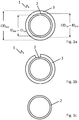
- the bimetallic tube 1 according to an embodiment of the present disclosure as depicted in figure 1a comprises a first metallic tube 2 and a second metallic tube 3.
- the first metallic tube 2 comprises, in weight% (wt-%), Fe+Cr ⁇ 1.0; C ⁇ 0.1; O ⁇ 0.2; Hf ⁇ 5.0; balance Zr and normally occurring impurities.
- the second metallic tube is an austenitic stainless steel comprising, in weight% (wt-%), C ⁇ 0.04; Mn ⁇ 3.0; P ⁇ 0.05; S ⁇ 0.04; Si ⁇ 1.0; Cr 15.0 - 30.0; Ni 7.0 - 25.0; Mo ⁇ 1.0; N ⁇ 0.10; balance Fe, and normally occurring impurities.
- Each of the first metallic tube 2 and the second metallic tube 3 comprises an inner diameter ID 1st or ID 2nd , respectively, and an outer diameter OD 1st or OD 2nd , respectively.
- the outer diameter OD 1st of the first metallic tube 2 is slightly smaller than the inner diameter ID 2nd of the second metallic tube 3, such that the first metallic tube 2 can be easily inserted into the second metallic tube 3.
- the first metallic tube 2 and the second metallic tube 3 are cold-drawn together through a drawing die.
- a force is applied to both the second metallic tube 3 and the first metallic tube 2 inserted therein yielding a plastic deformation and a reduction of the inner diameter ID 2nd of the second metallic tube 3 and of the outer diameter OD 1st of the first metallic tube 2.
- the outer diameter OD 1st of the first metallic tube 2 equals the inner diameter ID 2nd of the second metallic tube 3.
- the inner diameter ID BM of the bimetallic tube equals the inner diameter ID 1sd of the first metallic tube 2.
- the deformation of the first and second metallic tubes 2, 3 obtained during cold-drawing depends on size of the outer diameter OD 1st of the first metallic tube, the inner diameter ID 2nd and the outer diameter OD 2nd of the second metallic tube and the inner dimension of the drawing die.
- the parameters applied in the cold-drawing step are chosen, such that the force-fitting of the first metallic tube 2 to the second metallic tube 3 is at least 20 ⁇ m.
- the force-fitting is determined by the following procedure: The inner diameter (ID BM ) of the bimetallic tube (1) is measured; the second metallic tube (3) is removed from the first metallic tube (2); the inner diameter (ID 1st ) of the first metallic tube (2) is measured after removing the second metallic tube (3); the absolute value of the difference ID BM - ID 1st between the inner diameter ID BM of the bimetallic tube 1 and the inner diameter ID 1st of the first metallic tube 2 after the second metallic tube 3 has been removed is calculated.
- FIG 1b is a cross-section of the bimetallic tube 1 according to the embodiment of figure 1a .
- the second metallic tube 3 is removed by milling off the second metallic tube 3, the second metallic tube 3 could also be removed by pressing the first metallic tube 2 out of the second metallic tube 3. It is to be understood that a whole tube does not have to be used in the procedure, a sample of the bimetallic tube 1 is sufficient for obtaining the values of force-fitting.
- the first metallic tube 2 expands again and the inner diameter ID 1st of the first metallic tube 2 is measured.
- the outer diameter OD 1st and the inner diameter ID 1st of the first metallic tube 2 is larger than in the cold-drawn state shown in figure 1a .
- the absolute value of the difference ID BM - ID 1st between the inner diameter ID BM of the bimetallic tube 1 and the inner diameter ID 1st of the first metallic tube 2 after the second metallic tube 3 has been removed is calculated.
- the deformation applied in the cold-drawing step is sufficiently high when the value is at least 20 ⁇ m.
Landscapes
- Chemical & Material Sciences (AREA)
- Engineering & Computer Science (AREA)
- Mechanical Engineering (AREA)
- Materials Engineering (AREA)
- Metallurgy (AREA)
- Organic Chemistry (AREA)
- Metal Extraction Processes (AREA)
- Heat Treatment Of Articles (AREA)
- Rigid Pipes And Flexible Pipes (AREA)
- Laminated Bodies (AREA)
Description
- The present disclosure relates to a bimetallic tube comprising a first metallic tube having an inner diameter and an outer diameter, and a second metallic tube having an inner diameter and an outer diameter, wherein the first metallic tube is arranged within and force-fitted to the second metallic tube and wherein the first metallic tube comprises a zirconium (Zr) based alloy and wherein the second metallic tube comprises an austenitic stainless steel. The present disclosure also relates to a method for manufacturing a bimetallic tube comprising the steps of providing a first metallic tube having an inner diameter and an outer diameter, providing a second metallic tube having an inner diameter and an outer diameter, wherein the outer diameter of the first metallic tube is smaller than the inner diameter of the second tube, inserting the first metallic tube into the second metallic tube, cold-drawing the first and second metallic tubes together, such that the first and second metallic tubes are force-fitted together.
- Document
DE1146832B discloses a bimetallic tube with an inner Zr-based tube and an outer steel-based tube, which are force-fitted together. Further, documentGB1225896A - It is an aspect of the present disclosure to provide a bimetallic tube which will be corrosion resistant, and will facilitate the design and manufacture of industrial plants and equipment, such as heat exchangers. Further, the cost of manufacture of industrial plants and equipment will also be reduced by using the present bimetallic tube. Additionally, the present disclosure also provides a method for manufacture of such a bimetallic tube, which method will provide bimetallic tubes having strong mechanical bonds.
- Hence, at least one aspect underlying the present disclosure is solved by a bimetallic tube comprising a first metallic tube having an inner diameter and an outer diameter, and a second metallic tube having an inner diameter and an outer diameter, wherein the first metallic tube is arranged within and force-fitted to the second metallic tube and wherein the first metallic tube comprises, in weight% (wt-%), Fe+Cr ≤ 1.0; C ≤ 0.1; O ≤ 0.2; Hf ≤ 5.0; balance Zr and normally occurring impurities, and wherein the second metallic tube is an austenitic stainless steel comprising, in weight% (wt-%), C ≤ 0.04; Mn ≤ 3.0; P ≤ 0.05; S ≤ 0.04; Si ≤ 1.0; Cr 15.0 - 30.0; Ni 7.0 - 25.0; Mo ≤ 1.0; N ≤ 0.10; balance Fe and normally occurring impurities, and wherein the force-fitting of the first metallic tube to the second metallic tube is at least 20 µm determined by the following procedure:
- measuring the inner diameter (IDBM) of the bimetallic tube;
- removing the second metallic tube from the first metallic tube;
- measuring the inner diameter (ID1st) of the first metallic tube after the second metallic tube has been removed;
- calculating the absolute value of the difference (IDBM - ID1st) between the inner diameter (IDBM) of the bimetallic tube and the inner diameter (ID1st) of the first metallic tube after the second metallic tube has been removed.
- In terms of the present disclosure, if not excluded explicitly or technically impossible, the wording "smaller or equal" or the sign "≤", respectively, refer to an upper limit, wherein it is apparent for a person skilled in the art that the lower limit is zero, such there is no significant amount of the component exceeding the amount of normally occurring impurities. Accordingly the respective component is optional, but in case the component is present it does not exceed the maximum, i.e. upper limit.
- Combining a zirconium based alloy inner tube, i.e. the first metallic tube, having a composition as outlined above, and an austenitic stainless steel tube, i.e. the second metallic tube, having a composition as outlined above is surprisingly beneficial to obtain a bimetallic tube which will have high resistance against corrosion and also be mechanically stable.
- Since zirconium is a highly reactive element, it is very difficult to achieve a metallurgical bonding between a zirconium based alloy inner tube and an outer tube made from an austenitic stainless steel. Thus, when combing the inner tube and the outer tube for forming a bimetallic tube according to the present disclosure the inner and outer tubes are mechanically bonded to each other, i.e. force-fitted together.
- According to the present disclosure, one important parameter for determining the degree of force-fitting between the first metallic tube (the inner tube) and the second metallic tube (the outer tube), so that it is sufficient is to use a procedure wherein the inner diameter of the obtained bimetallic tube, i.e. the inner diameter of the inner tube in a state when it is force-fitted to the second metallic tube, is measured and compared with the inner diameter of the first tube after the second metallic tube has been removed from the first metallic tube. It should be noted that it is not necessary to use a whole tube for the procedure, a sample removed from the bimetallic tube comprising both the first and second tubes is sufficient for the procedure.
- One of the underlying concepts of the present disclosure is the finding of how a bond is achieved between the first and second metallic tube. Surprisingly, it has been found that by having a greater elastic spring back for the first metallic tube compared with the second metallic tube, a strong mechanical lock (bond) between the first and second metallic tubes is provided.
- Hence, the present inventors have found that surprisingly a strong mechanical lock (i.e. a mechanical bond) can be achieved by manufacturing a bimetallic tube by cold deformation. Without being bound to any theory, this is believed to depend on the plastic deformation which will occur during the deformation of the tubes and that a mechanical bond will be formed between the tubes when both the first and the second tubes have been plastically deformed.
- Hence, by means of the present disclosure, an adequate force-fitting between the first metallic tube and the second metallic tube is achieved when the force-fitting of first metallic tube to the second metallic tube is at least 20 µm, which value is determined by the following procedure:
- measuring the inner diameter (IDBM) of the bimetallic tube;
- removing the second metallic tube from the first metallic tube;
- measuring the inner diameter (ID1st) of the first metallic tube after the second metallic tube has been removed;
- calculating the absolute value of the difference (IDBM - ID1st) between the inner diameter (IDBM) of the bimetallic tube and the inner diameter (ID1st) of the first metallic tube after the second metallic tube has been removed.
- The procedure is a test for determining the degree of force-fitting between the first metallic tube and the second metallic tube, i.e. the strength of the mechanical bond. The procedure is the following:
- measuring the inner diameter (IDBM) of the bimetallic tube;
- removing the second metallic tube from the first metallic tube; measuring the inner diameter (ID1st) of the first metallic tube after the second metallic tube has been removed;
- calculating the absolute value of the difference (IDBM - ID1st) between the inner diameter (IDBM) of the bimetallic tube and the inner diameter (ID1st) of the first metallic tube after the second metallic tube has been removed, in case the parameters for the force-fitting have been chosen so to comply with the teaching of the present disclosure the obtained value should be at least 20 µm.
- The second metallic tube in an embodiment may be removed by milling or by pressing the first metallic tube out of the second metallic tube.
- As obvious for the skilled person, depending on the size of the tube, a whole bimetallic tube may be used for the procedure or a sample may be removed from the bimetallic tube and used for the procedure. Additionally, the inner diameter of the first metallic tube and/or the bimetallic tube may also be the average inner diameter obtained by measuring the inner diameter at several locations, e.g. at three different locations. Thus, the absolute value obtained by the present procedure is the bond strength (i.e. the contact pressure) between the inner and outer metallic tubes.
- The austenitic stainless steel comprises, in weight% (wt-%),
- C ≤ 0.04;
- Mn ≤ 3.0;
- P ≤ 0.05;
- S ≤ 0.04;
- Si ≤ 1.0;
- Cr 15.0 - 30.0;
- Ni 7.0 - 25.0;
- Mo ≤ 1.0;
- N ≤ 0.10;
- The amount of chromium contained in the second metallic tube will improve its resistance against most types of corrosion. In order to attain adequate corrosion resistance the amount of Cr present in the second metallic tube in an embodiment should be in a range of, in weight% (wt-%), 17 to 21 or, in weight% (wt-%), 18 to 20. In another embodiment, Cr is present in the second metallic tube in a range of in, weight% (wt-%), 23 to 27 or in weight% (wt-%), 24 to 26.
- In a further embodiment, the second metallic tube is selected from a first composition comprising, in weight% (wt-%), C ≤ 0.035; Si ≤ 0.4, Mn ≤ 2.0; P ≤ 0.045; S ≤ 0.03; Cr 18.0 - 20.0; Ni 8.5 - 12.0; balance Fe and normally occurring impurities, or a second composition comprising in weight% (wt-%), C ≤ 0.02; Si ≤ 0.15; Mn ≤ 2.0; P ≤ 0.02; S ≤ 0.015; Cr 24.0 - 26.0; Ni 19.0 - 22.0; N ≤ 0.1; balance Fe and normally occurring impurities. In particular, a second metallic tube of the second composition has an excellent resistance to corrosion in nitric acid, an excellent resistance to intergranular corrosion, a good resistance to pitting, and a good weldability.
- At least one aspect underlying the present disclosure is also solved by a method for manufacturing a bimetallic tube comprising the steps of providing a first metallic tube having an inner diameter and an outer diameter, providing a second metallic tube having an inner diameter and an outer diameter, wherein the outer diameter of the first metallic tube is smaller than the inner diameter of the second tube, inserting the first metallic tube into the second metallic tube, cold-drawing the first and second metallic tubes together, such that the first and second metallic tubes are force-fitted together, wherein in the step of providing the first metallic tube, the first metallic tube comprises, in weight% (wt-%), Fe+Cr ≤ 1.0; C ≤ 0.1; O ≤ 0.2; Hf ≤ 5.0; balance Zr and normally occurring impurities, wherein in the step of providing the second metallic tube, the second metallic tube is an austenitic stainless steel comprising, in weight% (wt-%), C ≤ 0.04; Mn ≤ 3.0; P ≤ 0.05; S ≤ 0.04; Si ≤ 1.0; Cr 15.0 - 30.0; Ni 7.0 - 25.0; Mo ≤ 1.0; N ≤ 0.10; balance Fe, and normally occurring impurities, wherein after the step of cold-drawing, in case the parameters for the force-fitting have been chosen so to comply with the teaching of the present disclosure, the force-fitting of the first metallic tube to the second metallic tube is at least 20 µm determined by the following procedure:
- measuring the inner diameter (IDBM) of the bimetallic tube;
- removing the second metallic tube from the first metallic tube;
- measuring the inner diameter (ID1st) of the first metallic tube after the second metallic tube has been removed;
- calculating the absolute value of the difference (IDBM - ID1st) between the inner diameter (IDBM) of the bimetallic tube and the inner diameter (ID1st) of the first metallic tube after the second metallic tube has been removed.
- According to the present disclosure the bimetallic tube is manufactured by providing a first metallic tube with an inner diameter and an outer diameter, and by providing a second metallic tube with an inner diameter and an outer diameter. The outer diameter of the first metallic tube is smaller than the inner diameter of the second metallic tube.
- After providing the first metallic tube and the second metallic tube, the first metallic tube is inserted into the second metallic tube. Afterwards the first metallic tube and the second metallic tube are mechanically bonded to each other, i.e. force-fitted by cold-drawing the first and second metallic tubes together.
- By drawing the first metallic tube and the second metallic tube together through a drawing die, which has a diameter defining the outer diameter of the second metallic tube after drawing, the first metallic tube and the second metallic tube are force-fitted together so to form the bimetallic tube. In order to obtain a force-fitting between the first metallic tube and the second metallic tube, the diameter of the drawing die has to be smaller than the outer diameter of the second metallic tube. During the forming in the drawing die, the second metallic tube is plastically deformed, whereby the inner diameter of the second metallic tube is reduced, the first metallic tube is also plastically deformed and a force-fitting is obtained between the first and second metallic tubes.
- Accordingly, the outer diameter and the inner diameter of the second metallic tube before the cold-drawing step, the outer diameter and the inner diameter of the first metallic tube before the cold-drawing step, as well as the dimensions of the drawing die have to be adjusted in order to achieve the desired force-fitting.
- In order to obtain a bimetallic tube according to the present disclosure in the step of providing the first metallic tube, the first metallic tube comprises, in weight% (wt-%), Fe+Cr ≤ 1.0; C ≤ 0.1; O ≤ 0.2; Hf ≤ 5.0; balance Zr, and normally occurring impurities, wherein in the step of providing the second metallic tube, the second metallic tube is an austenitic stainless steel comprising, in weight% (wt-%), C ≤ 0.04; Mn ≤ 3.0;P ≤ 0.05; S ≤ 0.04; Si ≤ 1.0; Cr 15.0 - 30.0; Ni 7.0 - 25.0; Mo ≤ 1.0; N ≤ 0.10, balance Fe and normally occurring impurities. By doing so a bimetallic tube which is at the same time highly resistant against corrosion and mechanically stable is obtained.
- However, in order to obtain an adequate mechanical bonding between the first metallic tube and the second metallic tube, the parameter of the cold-drawing step are chosen, such that after the step of cold-drawing the force-fitting of the first metallic tube to the second metallic tube is at least 20 µm determined by the following procedure:
- measuring the inner diameter (IDBM) of the bimetallic tube;
- removing the second metallic tube from the first metallic tube;
- measuring the inner diameter (ID1st) of the first metallic tube after the second metallic tube has been removed;
- calculating the absolute value of the difference (IDBM - ID1st) between the inner diameter (IDBM) of the bimetallic tube and the inner diameter (ID1st) of the first metallic tube after the second metallic tube has been removed.
- As outlined above at least one benefit thereof is that the force between the first metallic tube and the second metallic tube is sufficiently high to obtain a strong and long-lasting bonding.
- The upper limit of the degree of cold deformation is set depending on the demands regarding elongation and hardness. Thus, in one embodiment, in the step of cold drawing, the outer diameter of the second tube is reduced 10 % or less compared to outer diameter of the second metallic tube before cold-drawing when the content of Cr present in the second metallic tube is in a range of from 17 to 21 weight% (wt-%), such as 18 to 20 weight% (wt-%). In a further embodiment, in the step of cold-drawing, the outer diameter of the second tube is reduced 4 % or less compared to outer diameter of the second metallic tube before cold-drawing when the content of Cr present in the second metallic tube is in a range of from 23 to 27 weight% (wt-%), such as 24 to 26 weight% (wt%).
- In yet another embodiment after the step of cold-drawing, the second metallic tube has an elongation of at least or equal to 35 % and a hardness of less than or equal to 90 HRB.
- In an embodiment in the steps of providing first and second metallic tubes the first metallic tube and/or the second metallic tube is heat-treated before the step of inserting the first metallic tube into the second metallic tube, for example the first and second metallic tubes may have been annealed and/or bright annealed.
- In a further embodiment in the steps of providing first and second metallic tubes, the first metallic tube and/or the second metallic tube are cold worked tubes, such as cold-drawn or pilgered tubes.
- In another embodiment in the step of providing the first metallic tube, the first metallic tube is a seamless tube.
- According to a further embodiment in the step of providing the first metallic tube, the average wall thickness of the first metallic tube is 0.3 mm to 2 mm. For instance, the average wall thickness of the first metallic tube can be 0.7 mm.
- In a further embodiment in the step of providing the second metallic tube, the second metallic tube is a seamless tube.
- In another embodiment in the step of providing the second metallic tube, the average wall thickness of the second metallic tube is 0.5 mm to 4 mm. For instance, the average wall thickness of the second metallic tube can be 1.6 mm.
- Hence, an advantage with this solution is that normal stainless steel tube sheets can be used nonetheless the corrosion resistance is enhanced since zirconium is used as an inner tube liner. The zirconium tube is a corrosion barrier and protects the tube from corrosion.
- Further advantages, features and applications of the present disclosure will become apparent from the following description of embodiments and the corresponding figures attached. The foregoing as well as the following detailed description of the embodiments will be better understood when read in conjunction with the appended drawings. It should be understood that the embodiments depicted are not limited to the precise arrangements and instrumentalities shown.
- Insofar as in the foregoing as well as the following detailed description of the embodiments and claims reference is made to either the bimetallic tube or the method for manufacturing a bimetallic tube, the features described are applicable for both the bimetallic tube and the method for manufacturing the bimetallic tube.
-
-
Figure 1a is schematic cross-section of a bimetallic tube according to an embodiment of the present disclosure. -
Figure 1b is a schematic cross-section of a bimetallic tube according to an embodiment of the present disclosure indicating the removal of the second metallic tube. -
Figure 1c is a schematic cross-section of the bimetallic tube according tofigure 1b with the first metallic tube left after removal of the second metallic tube. - The
bimetallic tube 1 according to an embodiment of the present disclosure as depicted infigure 1a comprises a firstmetallic tube 2 and a secondmetallic tube 3. The firstmetallic tube 2 comprises, in weight% (wt-%), Fe+Cr ≤ 1.0; C ≤ 0.1; O ≤ 0.2; Hf ≤ 5.0; balance Zr and normally occurring impurities. The second metallic tube is an austenitic stainless steel comprising, in weight% (wt-%), C ≤ 0.04; Mn ≤ 3.0; P ≤ 0.05; S ≤ 0.04; Si ≤ 1.0; Cr 15.0 - 30.0; Ni 7.0 - 25.0; Mo ≤ 1.0; N ≤ 0.10; balance Fe, and normally occurring impurities. - Each of the first
metallic tube 2 and the secondmetallic tube 3 comprises an inner diameter ID1st or ID2nd, respectively, and an outer diameter OD1st or OD2nd, respectively. Before cold-drawn together, the outer diameter OD1st of the firstmetallic tube 2 is slightly smaller than the inner diameter ID2nd of the secondmetallic tube 3, such that the firstmetallic tube 2 can be easily inserted into the secondmetallic tube 3. - Afterwards, i.e. after the first
metallic tube 2 has been inserted into the secondmetallic tube 3, the firstmetallic tube 2 and the secondmetallic tube 3 are cold-drawn together through a drawing die. During the cold-drawing step, a force is applied to both the secondmetallic tube 3 and the firstmetallic tube 2 inserted therein yielding a plastic deformation and a reduction of the inner diameter ID2nd of the secondmetallic tube 3 and of the outer diameter OD1st of the firstmetallic tube 2. In a state after cold-drawing, as it is depicted infigure 1a , the outer diameter OD1st of the firstmetallic tube 2 equals the inner diameter ID2nd of the secondmetallic tube 3. Further, in a state after cold-drawing, as it is depicted infigure 1a , the inner diameter IDBM of the bimetallic tube equals the inner diameter ID1sd of the firstmetallic tube 2. - The deformation of the first and second
metallic tubes metallic tube 2 to the secondmetallic tube 3 is at least 20 µm. - The force-fitting is determined by the following procedure: The inner diameter (IDBM) of the bimetallic tube (1) is measured; the second metallic tube (3) is removed from the first metallic tube (2); the inner diameter (ID1st) of the first metallic tube (2) is measured after removing the second metallic tube (3); the absolute value of the difference IDBM - ID1st between the inner diameter IDBM of the
bimetallic tube 1 and the inner diameter ID1st of the firstmetallic tube 2 after the secondmetallic tube 3 has been removed is calculated. - The removal of the second
metallic tube 3 from the firstmetallic tube 2 is indicated infigure 1b. Figure 1b is a cross-section of thebimetallic tube 1 according to the embodiment offigure 1a . Although in the present embodiment the secondmetallic tube 3 is removed by milling off the secondmetallic tube 3, the secondmetallic tube 3 could also be removed by pressing the firstmetallic tube 2 out of the secondmetallic tube 3. It is to be understood that a whole tube does not have to be used in the procedure, a sample of thebimetallic tube 1 is sufficient for obtaining the values of force-fitting. - After the second
metallic tube 3 has been completely removed from the firstmetallic tube 2, as it is depicted infigure 1c , the firstmetallic tube 2 expands again and the inner diameter ID1st of the firstmetallic tube 2 is measured. The outer diameter OD1st and the inner diameter ID1st of the firstmetallic tube 2 is larger than in the cold-drawn state shown infigure 1a . - The absolute value of the difference IDBM - ID1st between the inner diameter IDBM of the
bimetallic tube 1 and the inner diameter ID1st of the firstmetallic tube 2 after the secondmetallic tube 3 has been removed is calculated. By means of the present disclosure, the deformation applied in the cold-drawing step is sufficiently high when the value is at least 20 µm. - For purposes of original disclosure, it is pointed out that all features which are apparent for a person skilled in the art from the present description, the figures and the claims, even if they have only been described with further features, could be combined on their own or together with all the combinations of the features disclosed herein, if not excluded explicitly or technically impossible. A comprehensive explicit description of all possible combinations of features is only omitted in order to provide readability of the description.
- While the disclosure has been described with respect to a limited number of embodiments, it will be understood that the disclosure of which is not limited to those embodiments. The scope of protection of the present disclosure is only limited by the appended claims.
Claims (15)
- A bimetallic tube (1) comprising a first metallic tube (2) having an inner diameter (ID1st) and an outer diameter (OD2nd), and a second metallic tube (3) having an inner diameter (ID2nd) and an outer diameter (OD2nd), wherein the first metallic tube (2) is arranged within and force-fitted to the second metallic tube (3), wherein the first metallic tube (2) comprises, in weight%,Fe+Cr ≤ 1.0;C ≤ 0.1;O ≤ 0.2;Hf ≤ 5.0;balance Zr and normally occurring impurities,
and wherein the second metallic tube (3) is an austenitic stainless steel comprising, in weight,C ≤ 0.04;Mn ≤ 3.0;P ≤ 0.05;S ≤ 0.04;Si ≤ 1.0;Cr 15.0 - 30.0;Ni 7.0 - 25.0;Mo ≤ 1.0;N ≤ 0.10;balance Fe and normally occurring impurities,
and wherein the force-fitting of the first metallic tube (2) to the second metallic tube (3) is at least 20 µm determined by the following procedure:• measuring the inner diameter (IDBM) of the bimetallic tube (1);• removing the second metallic tube (3) from the first metallic tube (2);• measuring the inner diameter (ID1st) of the first metallic tube after the second metallic tube has been removed;• calculating the absolute value of the difference (IDBM - ID1st) between the inner diameter (IDBM) of the bimetallic tube (1) and the inner diameter (ID1st) of the first metallic tube (2) after the second metallic tube (3) has been removed. - The bimetallic tube (1) according to claim 1, wherein the content of Cr present in the second metallic tube (3) is in a range of from 17 to 21 weight%, such as 18 to 20 weight%.
- The bimetallic tube (1) according to claim 1, wherein the content of Cr present in the second metallic tube (3) is in a range of from 23 to 27 weight%, such as 24 to 26 weight%.
- A method for manufacturing a bimetallic tube (1) comprising the steps of; providing a first metallic tube (2) having an inner diameter (ID1st) and an outer diameter (ODist), providing a second metallic tube (3) having an inner diameter (ID2nd) and an outer diameter (OD2nd), wherein the outer diameter (OD1st) of the first metallic tube (2) is smaller than the inner diameter (ID2nd) of the second tube (3), inserting the first metallic tube (2) into the second metallic tube (3), cold-drawing the first and second metallic tubes (2, 3) together, such that the first and second metallic tubes (2, 3) are force-fitted together, wherein in the step of providing the first metallic tube (2), the first metallic tube (2) comprises, in weight%;Fe+Cr ≤ 1.0;C ≤ 0.1;O ≤ 0.2;Hf ≤ 5.0;balance Zr and normally occurring impurities,
and wherein in the step of providing the second metallic tube (3), the second metallic tube (3) is an austenitic stainless steel comprising, in weight%;C ≤ 0.04;Mn ≤ 3.0;P ≤ 0.05;S ≤ 0.04;Si ≤ 1.0;Cr 15.0 - 30.0;Ni 7.0 - 25.0;Mo ≤ 1.0;N ≤ 0.10;balance Fe and normally occurring impurities,
and wherein after the step of cold-drawing the first metallic tube (2) is force-fitted to the second metallic tube (3) so that the spring back is least 20 µm determined by the following procedure:• measuring the inner diameter (IDBM) of the bimetallic tube;• removing the second metallic tube (3) from the first metallic tube (2);• measuring the inner diameter (ID1st) of the first metallic tube after the second metallic tube has been removed;• calculating the absolute value of the difference (IDBM - ID1st) between the inner diameter (IDBM) of the bimetallic tube (1) and the inner diameter (ID1st) of the first metallic tube (2) after the second metallic tube (3) has been removed. - The bimetallic tube (1) according to claim 4, wherein the content of Cr present in the second metallic tube (3) is in a range of from 17 to 21 weight%, such as 18 to 20 weight%.
- The bimetallic tube (1) according to claim 4, wherein the content of Cr present in the second metallic tube (3) is in a range of from 23 to 27 weight%, such as 24 to 26 weight%.
- The method according to claims 4 or 5, characterized in that in the step of cold-drawing, the outer diameter (OD2nd) of the second tube (3) is reduced 10 % or less compared to outer diameter (OD2nd) of the second metallic tube (3) before cold-drawing.
- The method according to claim 4 or claim 6, characterized in that in the step of cold-drawing, the outer diameter (OD2nd) of the second tube (3) is reduced 4 % or less compared to outer diameter (OD2nd) of the second metallic tube (3) before cold-drawing.
- The method according to any one of claims 4 to 8, characterized in that after the step of cold-drawing the second metallic tube (3) has an elongation of at least or equal to 35 % and a hardness not more than or equal to 90 HRB.
- The method according to any one of claims 4 to 9, characterized in that in the step of providing the first metallic tube (2) and/or the second metallic tube (3) is heat-treated before the step of inserting the first metallic tube (2) into the second metallic tube.
- The method according to any one of claims 4 to 10, characterized in that in the steps of providing first and second metallic tubes (2, 3), the first metallic tube (2) and/or the second metallic tube (3) are cold worked tubes, such as cold-drawn or pilgered tubes.
- The method according to any one of claims 4 to 11, characterized in that in the step of providing the first metallic tube (2), the first metallic tube (2) is a seamless tube.
- The method according to any one of claims 4 to 12, characterized in that in the step of providing the first metallic tube (2), the average wall thickness of the first metallic tube (2) is 0.3 mm to 2 mm.
- The method according to any one of claims 4 to 13, characterized in that in the step of providing the second metallic tube (3), the second metallic tube (3) is a seamless tube.
- The method according to any one of claims 4 to 14, characterized in that in the step of providing the second metallic tube (3), the average wall thickness of the second metallic tube (3) is 0.5 mm to 4 mm.
Applications Claiming Priority (2)
| Application Number | Priority Date | Filing Date | Title |
|---|---|---|---|
| EP16177637 | 2016-07-01 | ||
| PCT/EP2017/066254 WO2018002295A1 (en) | 2016-07-01 | 2017-06-30 | Bimetallic tube and method for manufacturing a bimetallic tube |
Publications (2)
| Publication Number | Publication Date |
|---|---|
| EP3478866A1 EP3478866A1 (en) | 2019-05-08 |
| EP3478866B1 true EP3478866B1 (en) | 2020-08-05 |
Family
ID=56403961
Family Applications (1)
| Application Number | Title | Priority Date | Filing Date |
|---|---|---|---|
| EP17732486.0A Active EP3478866B1 (en) | 2016-07-01 | 2017-06-30 | Bimetallic tube and method for manufacturing a bimetallic tube |
Country Status (5)
| Country | Link |
|---|---|
| US (1) | US10994319B2 (en) |
| EP (1) | EP3478866B1 (en) |
| JP (1) | JP2019527296A (en) |
| ES (1) | ES2823164T3 (en) |
| WO (1) | WO2018002295A1 (en) |
Families Citing this family (3)
| Publication number | Priority date | Publication date | Assignee | Title |
|---|---|---|---|---|
| DE102019104536A1 (en) * | 2019-02-22 | 2020-08-27 | Sandvik Materials Technology Deutschland Gmbh | Pipe structure and method of making such a pipe structure |
| US11946130B2 (en) * | 2019-12-26 | 2024-04-02 | Joint-Stock Company “Tvel” | Method of manufacturing zirconium alloy tubular products |
| CN116479319B (en) * | 2022-01-13 | 2025-02-18 | 宝山钢铁股份有限公司 | A high-strength pipe resistant to ozone corrosion and a manufacturing method thereof |
Family Cites Families (9)
| Publication number | Priority date | Publication date | Assignee | Title |
|---|---|---|---|---|
| DE1146832B (en) * | 1960-01-21 | 1963-04-11 | Siemens Ag | Process for the production of double-walled tubes for fuel rods of nuclear reactors |
| FR1525045A (en) * | 1966-10-14 | 1968-05-17 | Commissariat Energie Atomique | Method of joining two tubular elements made of non-weldable materials and the resulting junction |
| DE1608157B1 (en) * | 1968-03-14 | 1971-12-23 | Kernforschung Gmbh Ges Fuer | Corrosion-resistant composite material for structural parts and fuel element casings in nuclear reactors |
| JPS5225995A (en) * | 1975-08-25 | 1977-02-26 | Hitachi Ltd | Control element |
| SE447804B (en) * | 1983-04-20 | 1986-12-15 | Kuroki Kogyosho Kk | PROCEDURE FOR MANUFACTURING COMPOSITE STALLS |
| IT1209532B (en) * | 1984-04-20 | 1989-08-30 | Snam Progetti | PROCESS FOR THE SYNTHESIS OF UREA AND MATERIAL USED IN ITSELF. |
| JPH02121784A (en) * | 1988-10-31 | 1990-05-09 | Sumitomo Metal Ind Ltd | Manufacture of clad pipe |
| BR102013021664B1 (en) * | 2013-08-23 | 2020-11-10 | Vallourec Soluções Tubulares Do Brasil S.A | process for production of clad tube by drawing and clad tube |
| CN106078086B (en) * | 2016-06-12 | 2020-11-10 | 上海核工程研究设计院 | A kind of nuclear fuel element cladding zirconium alloy stainless steel composite tube and preparation method thereof |
-
2017
- 2017-06-30 ES ES17732486T patent/ES2823164T3/en active Active
- 2017-06-30 JP JP2018568926A patent/JP2019527296A/en active Pending
- 2017-06-30 WO PCT/EP2017/066254 patent/WO2018002295A1/en not_active Ceased
- 2017-06-30 EP EP17732486.0A patent/EP3478866B1/en active Active
- 2017-06-30 US US16/313,240 patent/US10994319B2/en active Active
Non-Patent Citations (1)
| Title |
|---|
| None * |
Also Published As
| Publication number | Publication date |
|---|---|
| EP3478866A1 (en) | 2019-05-08 |
| US10994319B2 (en) | 2021-05-04 |
| WO2018002295A1 (en) | 2018-01-04 |
| US20190168274A1 (en) | 2019-06-06 |
| ES2823164T3 (en) | 2021-05-06 |
| JP2019527296A (en) | 2019-09-26 |
Similar Documents
| Publication | Publication Date | Title |
|---|---|---|
| EP2481824B1 (en) | Pure titanium sheet excellent in balance between stamping formability and strenght | |
| EP2434030B1 (en) | Stainless steel for oil well, stainless steel pipe for oil well, and process for production of stainless steel for oil well | |
| US5286310A (en) | Low nickel, copper containing chromium-nickel-manganese-copper-nitrogen austenitic stainless steel | |
| US20120034126A1 (en) | STAINLESS AUSTENITIC LOW Ni STEEL ALLOY | |
| US10994319B2 (en) | Bimetallic tube and method for manufacturing a bimetallic tube | |
| EP2796220B1 (en) | Method for designing die for press forming | |
| EP2690188A1 (en) | Austenite system alloy pipe and manufacturing method thereof | |
| US20220145438A1 (en) | Duplex stainless steel material | |
| KR101943253B1 (en) | Titanium plates, plates for heat exchangers and separators for fuel cells | |
| EP1293583B1 (en) | Ni based alloy, method for producing the same, and forging die | |
| JP3989790B2 (en) | Ferritic stainless steel sheet with excellent press formability and manufacturing method thereof | |
| KR20140004793A (en) | Pure titanium sheet having excellent balance between press formability and strength and excellent corrosion resistance, and process for manufacturing same | |
| JP6515340B2 (en) | Oil well tube | |
| US6312834B1 (en) | Clad material and method of manufacturing the material | |
| JP7103588B2 (en) | Cu—Al—Mn-based shape memory alloy molded product having a threaded portion and its manufacturing method | |
| JP6578810B2 (en) | Oil well pipe | |
| KR20230098261A (en) | 2-phase stainless steel sheet, 2-phase stainless steel hot-rolled sheet, and manufacturing method of 2-phase stainless steel sheet | |
| JP2011164072A (en) | Diaphragm, pressure sensor, and manufacturing method of diaphragm | |
| EP2607513B1 (en) | Shape memory stainless steels with rare earth elements Ce and La | |
| US20250059631A1 (en) | Alpha + beta titanium alloy shape and method for manufacturing the same | |
| JP7090514B2 (en) | How to manufacture metal gasket intermediate products and metal gaskets | |
| JP5683432B2 (en) | Rolled copper foil | |
| JP6895864B2 (en) | Duplex stainless steel, duplex stainless steel plate and duplex stainless linear steel with excellent corrosion resistance on sheared surfaces | |
| JP5854409B2 (en) | Diaphragm, pressure sensor, and manufacturing method of diaphragm | |
| US20240093809A1 (en) | High pressure tube and method of manufacturing the same |
Legal Events
| Date | Code | Title | Description |
|---|---|---|---|
| STAA | Information on the status of an ep patent application or granted ep patent |
Free format text: STATUS: UNKNOWN |
|
| STAA | Information on the status of an ep patent application or granted ep patent |
Free format text: STATUS: THE INTERNATIONAL PUBLICATION HAS BEEN MADE |
|
| PUAI | Public reference made under article 153(3) epc to a published international application that has entered the european phase |
Free format text: ORIGINAL CODE: 0009012 |
|
| STAA | Information on the status of an ep patent application or granted ep patent |
Free format text: STATUS: REQUEST FOR EXAMINATION WAS MADE |
|
| 17P | Request for examination filed |
Effective date: 20190201 |
|
| AK | Designated contracting states |
Kind code of ref document: A1 Designated state(s): AL AT BE BG CH CY CZ DE DK EE ES FI FR GB GR HR HU IE IS IT LI LT LU LV MC MK MT NL NO PL PT RO RS SE SI SK SM TR |
|
| AX | Request for extension of the european patent |
Extension state: BA ME |
|
| DAV | Request for validation of the european patent (deleted) | ||
| DAX | Request for extension of the european patent (deleted) | ||
| GRAP | Despatch of communication of intention to grant a patent |
Free format text: ORIGINAL CODE: EPIDOSNIGR1 |
|
| STAA | Information on the status of an ep patent application or granted ep patent |
Free format text: STATUS: GRANT OF PATENT IS INTENDED |
|
| INTG | Intention to grant announced |
Effective date: 20200219 |
|
| GRAS | Grant fee paid |
Free format text: ORIGINAL CODE: EPIDOSNIGR3 |
|
| GRAA | (expected) grant |
Free format text: ORIGINAL CODE: 0009210 |
|
| STAA | Information on the status of an ep patent application or granted ep patent |
Free format text: STATUS: THE PATENT HAS BEEN GRANTED |
|
| AK | Designated contracting states |
Kind code of ref document: B1 Designated state(s): AL AT BE BG CH CY CZ DE DK EE ES FI FR GB GR HR HU IE IS IT LI LT LU LV MC MK MT NL NO PL PT RO RS SE SI SK SM TR |
|
| REG | Reference to a national code |
Ref country code: GB Ref legal event code: FG4D |
|
| REG | Reference to a national code |
Ref country code: CH Ref legal event code: EP |
|
| REG | Reference to a national code |
Ref country code: AT Ref legal event code: REF Ref document number: 1298806 Country of ref document: AT Kind code of ref document: T Effective date: 20200815 |
|
| REG | Reference to a national code |
Ref country code: DE Ref legal event code: R096 Ref document number: 602017021093 Country of ref document: DE |
|
| REG | Reference to a national code |
Ref country code: IE Ref legal event code: FG4D |
|
| REG | Reference to a national code |
Ref country code: FI Ref legal event code: FGE |
|
| REG | Reference to a national code |
Ref country code: SE Ref legal event code: TRGR |
|
| REG | Reference to a national code |
Ref country code: LT Ref legal event code: MG4D |
|
| REG | Reference to a national code |
Ref country code: NL Ref legal event code: MP Effective date: 20200805 |
|
| REG | Reference to a national code |
Ref country code: AT Ref legal event code: MK05 Ref document number: 1298806 Country of ref document: AT Kind code of ref document: T Effective date: 20200805 |
|
| PG25 | Lapsed in a contracting state [announced via postgrant information from national office to epo] |
Ref country code: LT Free format text: LAPSE BECAUSE OF FAILURE TO SUBMIT A TRANSLATION OF THE DESCRIPTION OR TO PAY THE FEE WITHIN THE PRESCRIBED TIME-LIMIT Effective date: 20200805 Ref country code: AT Free format text: LAPSE BECAUSE OF FAILURE TO SUBMIT A TRANSLATION OF THE DESCRIPTION OR TO PAY THE FEE WITHIN THE PRESCRIBED TIME-LIMIT Effective date: 20200805 Ref country code: GR Free format text: LAPSE BECAUSE OF FAILURE TO SUBMIT A TRANSLATION OF THE DESCRIPTION OR TO PAY THE FEE WITHIN THE PRESCRIBED TIME-LIMIT Effective date: 20201106 Ref country code: NO Free format text: LAPSE BECAUSE OF FAILURE TO SUBMIT A TRANSLATION OF THE DESCRIPTION OR TO PAY THE FEE WITHIN THE PRESCRIBED TIME-LIMIT Effective date: 20201105 Ref country code: PT Free format text: LAPSE BECAUSE OF FAILURE TO SUBMIT A TRANSLATION OF THE DESCRIPTION OR TO PAY THE FEE WITHIN THE PRESCRIBED TIME-LIMIT Effective date: 20201207 Ref country code: BG Free format text: LAPSE BECAUSE OF FAILURE TO SUBMIT A TRANSLATION OF THE DESCRIPTION OR TO PAY THE FEE WITHIN THE PRESCRIBED TIME-LIMIT Effective date: 20201105 Ref country code: HR Free format text: LAPSE BECAUSE OF FAILURE TO SUBMIT A TRANSLATION OF THE DESCRIPTION OR TO PAY THE FEE WITHIN THE PRESCRIBED TIME-LIMIT Effective date: 20200805 |
|
| PG25 | Lapsed in a contracting state [announced via postgrant information from national office to epo] |
Ref country code: PL Free format text: LAPSE BECAUSE OF FAILURE TO SUBMIT A TRANSLATION OF THE DESCRIPTION OR TO PAY THE FEE WITHIN THE PRESCRIBED TIME-LIMIT Effective date: 20200805 Ref country code: RS Free format text: LAPSE BECAUSE OF FAILURE TO SUBMIT A TRANSLATION OF THE DESCRIPTION OR TO PAY THE FEE WITHIN THE PRESCRIBED TIME-LIMIT Effective date: 20200805 Ref country code: NL Free format text: LAPSE BECAUSE OF FAILURE TO SUBMIT A TRANSLATION OF THE DESCRIPTION OR TO PAY THE FEE WITHIN THE PRESCRIBED TIME-LIMIT Effective date: 20200805 Ref country code: LV Free format text: LAPSE BECAUSE OF FAILURE TO SUBMIT A TRANSLATION OF THE DESCRIPTION OR TO PAY THE FEE WITHIN THE PRESCRIBED TIME-LIMIT Effective date: 20200805 Ref country code: IS Free format text: LAPSE BECAUSE OF FAILURE TO SUBMIT A TRANSLATION OF THE DESCRIPTION OR TO PAY THE FEE WITHIN THE PRESCRIBED TIME-LIMIT Effective date: 20201205 |
|
| PG25 | Lapsed in a contracting state [announced via postgrant information from national office to epo] |
Ref country code: DK Free format text: LAPSE BECAUSE OF FAILURE TO SUBMIT A TRANSLATION OF THE DESCRIPTION OR TO PAY THE FEE WITHIN THE PRESCRIBED TIME-LIMIT Effective date: 20200805 Ref country code: RO Free format text: LAPSE BECAUSE OF FAILURE TO SUBMIT A TRANSLATION OF THE DESCRIPTION OR TO PAY THE FEE WITHIN THE PRESCRIBED TIME-LIMIT Effective date: 20200805 Ref country code: EE Free format text: LAPSE BECAUSE OF FAILURE TO SUBMIT A TRANSLATION OF THE DESCRIPTION OR TO PAY THE FEE WITHIN THE PRESCRIBED TIME-LIMIT Effective date: 20200805 Ref country code: SM Free format text: LAPSE BECAUSE OF FAILURE TO SUBMIT A TRANSLATION OF THE DESCRIPTION OR TO PAY THE FEE WITHIN THE PRESCRIBED TIME-LIMIT Effective date: 20200805 |
|
| REG | Reference to a national code |
Ref country code: ES Ref legal event code: FG2A Ref document number: 2823164 Country of ref document: ES Kind code of ref document: T3 Effective date: 20210506 |
|
| REG | Reference to a national code |
Ref country code: DE Ref legal event code: R097 Ref document number: 602017021093 Country of ref document: DE |
|
| PG25 | Lapsed in a contracting state [announced via postgrant information from national office to epo] |
Ref country code: AL Free format text: LAPSE BECAUSE OF FAILURE TO SUBMIT A TRANSLATION OF THE DESCRIPTION OR TO PAY THE FEE WITHIN THE PRESCRIBED TIME-LIMIT Effective date: 20200805 |
|
| PLBE | No opposition filed within time limit |
Free format text: ORIGINAL CODE: 0009261 |
|
| STAA | Information on the status of an ep patent application or granted ep patent |
Free format text: STATUS: NO OPPOSITION FILED WITHIN TIME LIMIT |
|
| PG25 | Lapsed in a contracting state [announced via postgrant information from national office to epo] |
Ref country code: SK Free format text: LAPSE BECAUSE OF FAILURE TO SUBMIT A TRANSLATION OF THE DESCRIPTION OR TO PAY THE FEE WITHIN THE PRESCRIBED TIME-LIMIT Effective date: 20200805 |
|
| 26N | No opposition filed |
Effective date: 20210507 |
|
| PG25 | Lapsed in a contracting state [announced via postgrant information from national office to epo] |
Ref country code: IT Free format text: LAPSE BECAUSE OF FAILURE TO SUBMIT A TRANSLATION OF THE DESCRIPTION OR TO PAY THE FEE WITHIN THE PRESCRIBED TIME-LIMIT Effective date: 20200805 |
|
| PG25 | Lapsed in a contracting state [announced via postgrant information from national office to epo] |
Ref country code: SI Free format text: LAPSE BECAUSE OF FAILURE TO SUBMIT A TRANSLATION OF THE DESCRIPTION OR TO PAY THE FEE WITHIN THE PRESCRIBED TIME-LIMIT Effective date: 20200805 |
|
| PG25 | Lapsed in a contracting state [announced via postgrant information from national office to epo] |
Ref country code: MC Free format text: LAPSE BECAUSE OF FAILURE TO SUBMIT A TRANSLATION OF THE DESCRIPTION OR TO PAY THE FEE WITHIN THE PRESCRIBED TIME-LIMIT Effective date: 20200805 |
|
| REG | Reference to a national code |
Ref country code: CH Ref legal event code: PL |
|
| REG | Reference to a national code |
Ref country code: BE Ref legal event code: MM Effective date: 20210630 |
|
| PG25 | Lapsed in a contracting state [announced via postgrant information from national office to epo] |
Ref country code: LU Free format text: LAPSE BECAUSE OF NON-PAYMENT OF DUE FEES Effective date: 20210630 |
|
| PG25 | Lapsed in a contracting state [announced via postgrant information from national office to epo] |
Ref country code: LI Free format text: LAPSE BECAUSE OF NON-PAYMENT OF DUE FEES Effective date: 20210630 Ref country code: IE Free format text: LAPSE BECAUSE OF NON-PAYMENT OF DUE FEES Effective date: 20210630 Ref country code: CH Free format text: LAPSE BECAUSE OF NON-PAYMENT OF DUE FEES Effective date: 20210630 |
|
| PG25 | Lapsed in a contracting state [announced via postgrant information from national office to epo] |
Ref country code: BE Free format text: LAPSE BECAUSE OF NON-PAYMENT OF DUE FEES Effective date: 20210630 |
|
| PG25 | Lapsed in a contracting state [announced via postgrant information from national office to epo] |
Ref country code: CY Free format text: LAPSE BECAUSE OF FAILURE TO SUBMIT A TRANSLATION OF THE DESCRIPTION OR TO PAY THE FEE WITHIN THE PRESCRIBED TIME-LIMIT Effective date: 20200805 |
|
| P01 | Opt-out of the competence of the unified patent court (upc) registered |
Effective date: 20230526 |
|
| PG25 | Lapsed in a contracting state [announced via postgrant information from national office to epo] |
Ref country code: HU Free format text: LAPSE BECAUSE OF FAILURE TO SUBMIT A TRANSLATION OF THE DESCRIPTION OR TO PAY THE FEE WITHIN THE PRESCRIBED TIME-LIMIT; INVALID AB INITIO Effective date: 20170630 |
|
| REG | Reference to a national code |
Ref country code: GB Ref legal event code: 732E Free format text: REGISTERED BETWEEN 20231026 AND 20231101 |
|
| REG | Reference to a national code |
Ref country code: DE Ref legal event code: R081 Ref document number: 602017021093 Country of ref document: DE Owner name: ALLEIMA TUBE AB, SE Free format text: FORMER OWNER: SANDVIK INTELLECTUAL PROPERTY AB, SANDVIKEN, SE |
|
| PG25 | Lapsed in a contracting state [announced via postgrant information from national office to epo] |
Ref country code: MK Free format text: LAPSE BECAUSE OF FAILURE TO SUBMIT A TRANSLATION OF THE DESCRIPTION OR TO PAY THE FEE WITHIN THE PRESCRIBED TIME-LIMIT Effective date: 20200805 |
|
| PG25 | Lapsed in a contracting state [announced via postgrant information from national office to epo] |
Ref country code: MT Free format text: LAPSE BECAUSE OF FAILURE TO SUBMIT A TRANSLATION OF THE DESCRIPTION OR TO PAY THE FEE WITHIN THE PRESCRIBED TIME-LIMIT Effective date: 20200805 |
|
| REG | Reference to a national code |
Ref country code: ES Ref legal event code: PC2A Owner name: ALLEIMA TUBE AB Effective date: 20240927 |
|
| REG | Reference to a national code |
Ref country code: FI Ref legal event code: PCE Owner name: ALLEIMA TUBE AB |
|
| PGFP | Annual fee paid to national office [announced via postgrant information from national office to epo] |
Ref country code: FI Payment date: 20250620 Year of fee payment: 9 |
|
| PGFP | Annual fee paid to national office [announced via postgrant information from national office to epo] |
Ref country code: DE Payment date: 20250507 Year of fee payment: 9 |
|
| PGFP | Annual fee paid to national office [announced via postgrant information from national office to epo] |
Ref country code: GB Payment date: 20250508 Year of fee payment: 9 |
|
| PGFP | Annual fee paid to national office [announced via postgrant information from national office to epo] |
Ref country code: FR Payment date: 20250523 Year of fee payment: 9 |
|
| PGFP | Annual fee paid to national office [announced via postgrant information from national office to epo] |
Ref country code: CZ Payment date: 20250530 Year of fee payment: 9 |
|
| PGFP | Annual fee paid to national office [announced via postgrant information from national office to epo] |
Ref country code: SE Payment date: 20250514 Year of fee payment: 9 |
|
| PGFP | Annual fee paid to national office [announced via postgrant information from national office to epo] |
Ref country code: ES Payment date: 20250707 Year of fee payment: 9 |
|
| PG25 | Lapsed in a contracting state [announced via postgrant information from national office to epo] |
Ref country code: TR Free format text: LAPSE BECAUSE OF FAILURE TO SUBMIT A TRANSLATION OF THE DESCRIPTION OR TO PAY THE FEE WITHIN THE PRESCRIBED TIME-LIMIT Effective date: 20200805 |