EP3478238B1 - An electric stair-climbing wheelchair with a hybrid locomotion system - Google Patents
An electric stair-climbing wheelchair with a hybrid locomotion system Download PDFInfo
- Publication number
- EP3478238B1 EP3478238B1 EP17740785.5A EP17740785A EP3478238B1 EP 3478238 B1 EP3478238 B1 EP 3478238B1 EP 17740785 A EP17740785 A EP 17740785A EP 3478238 B1 EP3478238 B1 EP 3478238B1
- Authority
- EP
- European Patent Office
- Prior art keywords
- stair
- track
- wheels
- wheelchair
- climbing
- Prior art date
- Legal status (The legal status is an assumption and is not a legal conclusion. Google has not performed a legal analysis and makes no representation as to the accuracy of the status listed.)
- Active
Links
Images


Classifications
-
- A—HUMAN NECESSITIES
- A61—MEDICAL OR VETERINARY SCIENCE; HYGIENE
- A61G—TRANSPORT, PERSONAL CONVEYANCES, OR ACCOMMODATION SPECIALLY ADAPTED FOR PATIENTS OR DISABLED PERSONS; OPERATING TABLES OR CHAIRS; CHAIRS FOR DENTISTRY; FUNERAL DEVICES
- A61G5/00—Chairs or personal conveyances specially adapted for patients or disabled persons, e.g. wheelchairs
- A61G5/06—Chairs or personal conveyances specially adapted for patients or disabled persons, e.g. wheelchairs with obstacle mounting facilities, e.g. for climbing stairs, kerbs or steps
- A61G5/061—Chairs or personal conveyances specially adapted for patients or disabled persons, e.g. wheelchairs with obstacle mounting facilities, e.g. for climbing stairs, kerbs or steps for climbing stairs
-
- A—HUMAN NECESSITIES
- A61—MEDICAL OR VETERINARY SCIENCE; HYGIENE
- A61G—TRANSPORT, PERSONAL CONVEYANCES, OR ACCOMMODATION SPECIALLY ADAPTED FOR PATIENTS OR DISABLED PERSONS; OPERATING TABLES OR CHAIRS; CHAIRS FOR DENTISTRY; FUNERAL DEVICES
- A61G5/00—Chairs or personal conveyances specially adapted for patients or disabled persons, e.g. wheelchairs
- A61G5/06—Chairs or personal conveyances specially adapted for patients or disabled persons, e.g. wheelchairs with obstacle mounting facilities, e.g. for climbing stairs, kerbs or steps
- A61G5/063—Chairs or personal conveyances specially adapted for patients or disabled persons, e.g. wheelchairs with obstacle mounting facilities, e.g. for climbing stairs, kerbs or steps with eccentrically mounted wheels
- A61G5/065—Chairs or personal conveyances specially adapted for patients or disabled persons, e.g. wheelchairs with obstacle mounting facilities, e.g. for climbing stairs, kerbs or steps with eccentrically mounted wheels with three or more wheels mounted on a rotary cross member, e.g. spiders or spoked wheels with small wheels at the end of the spokes
-
- A—HUMAN NECESSITIES
- A61—MEDICAL OR VETERINARY SCIENCE; HYGIENE
- A61G—TRANSPORT, PERSONAL CONVEYANCES, OR ACCOMMODATION SPECIALLY ADAPTED FOR PATIENTS OR DISABLED PERSONS; OPERATING TABLES OR CHAIRS; CHAIRS FOR DENTISTRY; FUNERAL DEVICES
- A61G5/00—Chairs or personal conveyances specially adapted for patients or disabled persons, e.g. wheelchairs
- A61G5/06—Chairs or personal conveyances specially adapted for patients or disabled persons, e.g. wheelchairs with obstacle mounting facilities, e.g. for climbing stairs, kerbs or steps
- A61G5/066—Chairs or personal conveyances specially adapted for patients or disabled persons, e.g. wheelchairs with obstacle mounting facilities, e.g. for climbing stairs, kerbs or steps with endless belts
-
- A—HUMAN NECESSITIES
- A61—MEDICAL OR VETERINARY SCIENCE; HYGIENE
- A61G—TRANSPORT, PERSONAL CONVEYANCES, OR ACCOMMODATION SPECIALLY ADAPTED FOR PATIENTS OR DISABLED PERSONS; OPERATING TABLES OR CHAIRS; CHAIRS FOR DENTISTRY; FUNERAL DEVICES
- A61G5/00—Chairs or personal conveyances specially adapted for patients or disabled persons, e.g. wheelchairs
- A61G5/10—Parts, details or accessories
- A61G5/1078—Parts, details or accessories with shock absorbers or other suspension arrangements between wheels and frame
Definitions
- the present invention relates to the field of systems to assist the movement of people with disabilities or reduced mobility, in particular it refers to stair-climbing wheelchairs.
- the present invention refers more specifically to a stair-climbing wheelchair provided with a hybrid locomotion system according to the preamble of Claim 1.
- this solution is not equipped with motors for flat ground motion and has the disadvantage of allowing climbing architectural barriers only with the help of an assistant who keeps the wheelchair balanced.
- the wheelchair without an external aid does not show any condition of static balance, since in general the projection of its centre of gravity falls outside the area comprised between the wheel-stairs contact points, and almost always this area is reduced to an ideal segment between the contact points of the wheels, to the right and to the left, in contact with a single step.
- non-motorized front track allows to have a wheelchair which is substantially stable, lighter, less bulky and subject to less oscillations with respect to previously described wheelchairs, such solution does not ensure a correct distribution of contact forces in its front and rear support points, causing possible traction and grip problems of the wheelchair, in particular during the stair-climbing motion. Also, it is not able to generate a straight translational motion of the user of the wheelchair during the climbing of stair flights.
- a further example of stair-climbing wheelchair is disclosed in CN 204 233 314 U , which relates to an anti-skid device for an electric stair-climbing wheelchair.
- a pentacle wheel used for stair climbing is mounted on a power spindle and an air cylinder is arranged on a wheel chassis.
- the bottom end of an ejector rod of the air cylinder is fixed to a track frame body and the track frame body is positioned below the wheel chassis.
- a driving wheel and a driven wheel are mounted on the track frame body, respectively positioned at the two ends of the inner side of a track and meshed with the track.
- a driving chain wheel is further mounted on the power spindle and a driven chain wheel is fixed on the wheel axle of the driving wheel.
- driving power is provided by the power spindle of the existing electric wheelchair, so that the power device is not required to be additionally arranged and the structural design is reasonable.
- the object of the present invention is to overcome the drawbacks of the known art.
- it is an object of the present invention to provide a stair-climbing wheelchair with a hybrid locomotion system having characteristics of high safety and comfort for the user, and also a higher power autonomy.
- the basic idea of the present invention envisages to realize a stair-climbing wheelchair comprising a frame provided with a seat intended to accommodate a user to be transported, and a locomotion unit comprising a couple of clusters of wheels. Further, the wheelchair comprises passive supporting means that are movable between a stowed position wherein they are raised from the ground and an extracted position wherein they are in contact with the ground.
- the passive supporting means comprise a track configured in such a way that, in its extracted position, the frame rests at the front on the locomotion unit and at the rear on the track
- the stair-climbing wheelchair further comprises at least one mechanical device linked between the locomotion unit and the seat, adapted to cooperate with the track for compensating the oscillations of the seat generated by the movement of the couple of clusters of wheels, and configured in such a way as to allow a substantially translational motion of the seat during a stair-climbing motion of the stair-climbing wheelchair.
- front/at the front is used to indicate the side of the wheelchair, and each individual component thereof, that a user has in front of him/herself, while the term “rear/at the rear” is used to indicate the side of the wheelchair, and each individual component thereof, that a user has behind him/herself.
- At least one mechanical device of the wheelchair adapted to allow a translational motion of the seat during its motion comprises a cam-follower mechanism, wherein the cam is coupled to a connecting shaft connected to the couple of clusters of wheels, and wherein the follower is hinged to a supporting element integral with the seat.
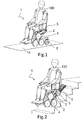
- Figures 1 and 2 illustrate overall views of a stair-climbing wheelchair 1 according to the invention.
- figure 1 shows the wheelchair 1 in flat ground motion conditions
- figure 2 shows the wheelchair in stair-climbing motion conditions.
- the stair-climbing wheelchair 1 comprises a frame 2, provided with a seat 3 intended to accommodate a user 100, in particular a user with disabilities or reduced mobility, and a locomotion unit 4 to allow the movement of the wheelchairs 1.
- the stair-climbing wheelchair 1 is an electric wheelchair, i.e. which is provided with an electric motor assembly adapted to transmit a torque to operate a transmission assembly connected to the locomotion unit 4, and which will be discussed in more detail thereafter.
- the wheelchair 1 further comprises passive supporting means (5, 6), idle or in any case non-motorized, connected to the frame 2, and movable between a stowed position wherein they are raised from the ground 1a, and an extracted position wherein they are in contact with the ground 1a.
- the supporting means comprise a track 6 and a pair of pivoting wheels 5.
- the supporting means comprise a track 6 and a pair of pivoting wheels 5.
- the supporting means In use, and in a condition of flat ground motion of the wheelchair 1 - as illustrated in figure 1 - it corresponds to a stowed position of the track 6 and to an extracted position of the pivoting wheels 5, in such a way that the track 6 is accommodated inside the volume occupied by the wheelchair 1, and the pivoting wheels 5 are in contact with the ground 1a.
- pivoting wheels 5 of the wheelchair 1 are illustrated in such a way that during its flat ground motion, i.e. in their extracted position, i.e. in contact with the ground 1a, they are positioned at the rear of locomotion unit 4, the pivoting wheels 5 can also be arranged at the front of the locomotion unit 4, when they are in their extracted position, simply entailing a slight modification of the framework structure of the wheelchair 1 with respect to the illustrated examples.
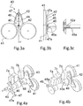
- the locomotion unit 4 comprises a couple of identical clusters of wheels 40 - of which only one is illustrated in the figures - positioned at the front of opposite sides of the frame 2 and mutually in axis.
- the couple of clusters of wheels 40 is mounted at a distance such as to minimize the overall dimension of the wheelchair 1 and to confer the necessary mobility even in confined spaces (e.g., to allow an easy passage through the internal doors in buildings).
- Each clusters of wheels preferably comprises three wheels 41, connected to a box-like body constituted by a supporting structure 42 - or planet carrier - and by a cover.
- the planet carrier 42 comprises a central portion from which three supporting arms 43 extend, each for a respective wheel 41 and angularly equidistant from one another, and is provided with a housing 44 for accommodating a gear train therein.
- the gear train is of the epicyclical type and comprises a sun gear 45, positioned centrally in the housing 44, integral with a drive shaft 45a and that meshes with three planet wheels 46, each positioned on a respective arm 43.
- the sun wheel 45 and the related drive shaft 45a are hollow in order to enclose a shaft 42a integral with the planet carrier 42.
- Each planet wheel 46 is hinged to the planet carrier 42 and allows to obtain the same direction of rotation between the sun wheel 45 and a second assembly of gears, in this case three gears 47.
- Each gear 47 of the second group of gears is arranged on a respective arm 43 and each meshes with a corresponding satellite wheel 46.
- each gear 47 of the second group of gears is hinged to the planet carrier 42 and integral to a shaft 47a on which the wheel 41, preferably in rubber, is rigidly mounted, destined to come into contact with the ground 1a.
- each clusters of wheels 40 of the locomotion unit 4 has two degrees of freedom: the rotation of the sun gear 45 and the rotation of the planet carrier 42 respectively controlled by the drive shaft 45a and by the shaft 42a.
- Figure 4a shows a first embodiment of the transmission assembly of the wheelchair 1 that, in order to simplify its structure and to ensure synchronous rotation of both cluster of wheels 40, provides a connecting shaft 48 that connects the shafts 42a controlling the rotation of the respective planet carriers 42.
- the couple of clusters of wheels 40 generally has three degrees of freedom since the rotations of both planet carriers 42 result coupled.
- an electric motor assembly comprising three gear motors, indicated in figure 4a with the references 7a, 7b and 7c.
- Two of the three gear motors 7a and 7b are coupled to a respective drive shaft 45a connected to the sun wheel 45 of a corresponding planet carrier 42, while the remaining gear motor 7c is coupled to the connecting shaft 48 and is adapted to manage the rotation of both planet carriers 42 of the couple of clusters of wheels 40.
- the gear motor 7c coupled to the connecting shaft 48 is configured to ensure an irreversibility of the rotational motion, in such a way as to maintain the wheelchair 1 in position also when the motor assembly is not powered.
- the connecting shaft connects the planet carriers of each cluster of wheels 40 and is mounted in a non-coaxial way with respect to the spin axis of the drive shafts 45a connected to the sun gears 45.
- two supporting elements 49 are provided integral with the frame 2, each disposed in the vicinity of the two planet carriers 42 and adapted to support the connecting shaft 48a.
- Each supporting element 49 supports at one end a coaxial hinge to a respective drive shaft 45a of the sun gears 45, and at the other end a coaxial hinge to the connecting shaft 48a.
- the connecting shaft 48a is coupled to the gear motor 7c adapted to control the motion of the two planet carriers 42, and to each of its ends a gear is keyed, which meshes with a corresponding gear mounted integral with a respective planet carrier 42 of the cluster of wheels 40.
- the gear motors 7a, 7b are mounted, adapted to control the rotation of the latter.
- the gear ratio between the gears mounted on the end of the connecting shaft 48a and the gears mounted integral with a respective planet carrier 42 is 3:1, so as to couple a complete rotation of the connecting shaft 48 with a 120° rotation of the cluster of wheels 40 during the stair-climbing motion, which corresponds to climbing a step.
- such configuration allows to limit the overall dimension of the transmission assembly, and facilitates and simplifies the assembly thereof in the stair-climbing wheelchair 1, since it does not require the presence of shafts and coaxial motors entailing a greater constructive complexity, such as hollow shafts and multiple hinges, for example.
- the frame 2 of the wheelchair 1 is shown.
- the frame 2 is constituted by a first and a second sub-frame mutually hinged by means of a couple of hinges (20a, 20b). Such coupling corresponds to hinge C in the diagram of figure 7 .
- the first sub-frame comprises a structure provided with a first rod 2a and a second rod 2b, intended to connect reciprocally the other components of the wheelchair 1.
- the two rods 2a, 2b are integral and parallel one another, i.e. they constitute a single rigid body that does not allow their relative rotation.
- each rod (2a, 2b) corresponds to segment PC.
- two drive shafts 45a of the respective sun gears 45 and two shafts 42a rotating the planet carriers 42 connected to the connecting shaft 48 are hinged in the point of the frame 2 indicated with P.
- the second sub-frame is constituted by a supporting element 30 integral with the seat 3 of the wheelchair 1, which corresponds to segment RC represented in figure 7 .
- the wheelchair 1 rests on two pivoting wheels 5, each mounted on one end of a movable rod 51, in such a way that, when the wheels are in contact with the ground 1a, they support the wheelchair 1 during the flat ground motion.
- each bar is hinged to the frame 2 at the opposite end of the end provided for the pivoting wheels 5.
- different embodiments can provide bars 51 hinged to the supporting element 30 of the seat 3.
- the movable bars 51 are hinged at one end of the frame 2 and, in particular, in correspondence of the planet carrier 42 of the cluster of wheels 40, they can be hinged at any other point belonging to the two bodies, provided that it allows the pivoting wheels 5 to move between the extracted position, in which they rest on the ground 1a - as illustrated in figures 5a, 5b , and the stowed position, in which they are raised from the ground 1a - as shown in figure 5c .
- the movement of the two movable bars 51 and of the relevant pivoting wheels 5 connected thereto occurs by the actuation of a linear or rotary actuator (not represented in the figures).
- the motion of the wheelchair 1 is controlled by the coordinated action of the two reduction gears 7a, 7b coupled to the drive shafts 45a of the solar gears 45, and of the gear motor 7c coupled to the connecting shaft 48 moving the planet carriers 42.
- the track 6, which comprises the hinge indicated with reference S, moves with a translational motion along a straight line, parallel to the plane lying on the edges of the steps of the stair.
- the latter is hinged to the track 6 in correspondence of the hinge S, and the distance between the point R belonging to the supporting member 30 of the seat 3 and the point P belonging to the planet carrier 42 of the cluster of wheels 40, is controlled in such a manner as to compensate for the motion of P with respect to R.
- the wheelchair 1 comprises at least one mechanical device linked between the locomotion unit 4 and the seat 3, adapted to cooperate with the track (6) for compensating the oscillations of the seat 3 generated by the movement of the couple of clusters of wheels 40, and configured in such a way as to allow a substantially translational motion of the seat 3 during the motion of the stair-climbing wheelchair 1.
- such mechanical device comprises a first mechanism that allows to connect the supporting element 30 of the seat 3 to the track 6, and a second mechanism that manages the distance between P and R as a function of the rotation of the cluster of wheels 40.
- the first mechanism can move the track 6 between the stowed position for flat ground motion (in which the track 6 is raised and is not in contact with the ground 1a) and the extracted position in which the track 6 rests on the stair during the climbing motion.
- the track 6 is idle, i.e. non-motorized, and at its maximum extension it preferably has a length greater than twice the maximum pitch between the steps of stairs that the wheelchair must climb (where pitch means the pitch is the hypotenuse of the triangle which has as catheti the riser and the tread of the step).
- the wheelchair 1 preferably provides a telescopic track.
- the telescopic track of the embodiment illustrated in the figures comprises a first portion 6a on which the previously described hinge S is positioned, having a substantially rectangular structure, each opposite long side thereof is wound by a belt 61 and are connected at one end by a cross member 62.
- Alternative embodiments may comprise a non-telescopic track, provided with a single belt (or for example with a rubber track), or a plurality of belts.
- the track 6 comprises one or more parts, connected to one another so as to be movable and such as to allow a retracted configuration in which the track 6 occupies a minimum volume, and an extended configuration of the latter in which it occupies a maximum volume.
- the opposite long sides are provided with a linear guide 63 which constrains the sliding of a second telescopic portion 6b of the track 6.
- the second telescopic portion 6b slides parallel inside the first fixed portion 6a, and it is also provided with belts 61 intended to come into contact with the plane of the stairs.
- An actuator (not represented in the figures) allows to pass from the retracted configuration ( figure 8 ) to the extended configuration ( figure 9 ) of the telescopic track, and vice versa.
- the retracted configuration minimizes the overall dimension of the track 6 inside the volume occupied by the wheelchair 1 during the flat ground motion, while the extended configuration ensures a sufficient length of track 6 during the stair-climbing motion.
- the second telescopic portion 6b results extracted in such a way as to expand the track 6 in a direction which extends at the rear of the wheelchair 1.
- the track 6 is shifted into the retracted or extended position by means of a mechanism connected to the supporting element 30 of the seat 3, which will be discussed in more detail shortly. With respect to such mechanism, the track 6 is further free to rotate about an axis perpendicular to the sagittal plane of the wheelchair 1 by means of a hinge 64, indicated with reference S in figure 7 .
- both the fixed portion 6a and the telescopic portion 6b of the track 6 provide distinct contact surfaces by means of belts (i.e. two parallel and spaced apart half-rollers), however not illustrated alternative embodiments, and as previously mentioned, may provide a single contact surface for the fixed portion 6a and for the telescopic portion 6b, for example.
- the mechanism allowing to shift the track 6 between the stowed position during the flat ground motion and the extracted position during the stair-climbing motion is shown.
- Such mechanism allows, moreover, to manage with continuity the distance of the frame 2 (especially that of the hinge indicated with letter C in figure 7 ) from the plane of the stairs during the different operative stages.
- the mechanism provides a bar connecting the hinge S integral to the fixed portion 6a of the track 6 to a hinge connected to the supporting element 30 of the seat 3. Thanks to this mechanism, the hinge is moved in the plane leaving free the rotation of the fixed portion 6a of the track 6 with respect to the supporting element 30.
- This solution is similar to the example shown in figure 10 , but deprived of the rods indicated by references 32 and 33.
- a different alternative embodiment of such mechanism illustrated in figure 10 , provides two equal and parallel articulated parallelograms moving at the two sides of the track 6.
- Each articulated parallelogram is constituted by the supporting element 30 of the seat 3, which is hinged to the ends of two rods (31, 32), the latter in turn hinged to the opposite ends of a connecting rod 33, hinged to the fixed portion 6a of the track 6.
- the two rods (31, 32) have the same length and the connecting rod 33 has a length equal to the distance between the hinges 34a and 34b provided on the supporting element 30 of the seat 3.
- the articulated parallelogram mechanism thus realized allows to move in the plane the hinge S of the fixed portion 6a of the track 6, while also translating the connecting rod 33, which is always parallel to the segment joining the hinges (34a, 34b) provided on the supporting element 30 of the seat 3.
- This solution allows to introduce limitations to the rotation of the fixed portion 6a of the belt 6 with respect to the connecting rod 33, for example by adding contact surfaces on the latter, and allowing to improve the mobility control of the track 6, without introducing further actuation systems.
- Figures 11a, 11b and 11c show the track 6 provided with the articulated quadrangle mechanism in three different operating configurations that maintain its inclination constant with respect to the connecting rod 33.
- a possible embodiment for the mechanism can provide the use of a single articulated parallelogram.
- the articulated quadrangle mechanism provides a hook 36 integral with the telescopic portion 6b of the track 6 adapted to engage, in a closed track configuration, a pin 37 integral with the connecting rod 33.
- This solution makes the fixed portion 6a of the track 6 integral with the connecting rod 33 in the closed track configuration.
- the motion system of the track 6 with respect to the supporting element 30 may also be implemented by mechanisms having two or three degrees of freedom actuated independently, that manage the relative position between the two elements.
- this latter provides not only the mechanism just described that allows to connect the supporting element 30 of the seat 3 to the track 6, but also a second mechanism to manage the distance between the point R belonging to the supporting member 30 of the seat 3 and the point P belonging to the planet carrier 42 of the clusters of wheels 40, in such a way as to compensate for the motion of P with respect to R.
- a first embodiment of this second mechanism illustrated in figure 13a , provides a system with a cam and a follower.
- the cam 80 is integral with the connecting shaft 48 that connects the shafts 42a controlling the rotation of the planet carriers 42 of the clusters of wheels 40, then rotates together with the clusters of wheels;
- the follower 81 is for example a roller tappet, and it is hinged to the supporting element 30 of the seat 3.
- the mechanism can control the distance between P and R - see figure 7 - so as to compensate the movement of point P during the rotation of the clusters of wheels 40 and can ensure a translational motion of the seat.
- This solution also allows to control the distance PR in a passive manner, i.e. by operating without the aid of control and actuated systems, but by exploiting the gear motors (7a, 7b, 7c) of the clusters of wheels 40, to the advantage of the constructive simplification of wheelchair 1.
- a gear wheel is keyed, which meshes with a corresponding gear mounted integral with a respective planet carrier 42 of the cluster of wheels 40.
- such pair of gears preferably have a gear ratio of 3:1, such configuration allows to couple a complete rotation of the connecting shaft 48a with a 120° of rotation of the cluster of wheels 40, rotation corresponding to the climbing of a step during the stair-climbing motion of the wheelchair 1.
- the cam 80a is integral with the connecting shaft 48a rotating together with the clusters of wheels, and is coupled to the follower 81a, the latter hinged to the supporting element 30 of the seat 3.
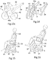
- FIG. 14 An alternative embodiment, illustrated in figure 14 , provides that the mechanism of motion compensation of P with respect to R is implemented by an active control by means of an actuator 9.
- the actuator 9 is hinged at one end to the connecting shaft 48 of the planet carriers 42, and at the other end to the supporting element 30 of the seat 3.
- the motion compensation mechanism of P with respect to R provides a combined use of the cam-follower mechanism and of the control system by means of the actuator, which were previously described.
- the wheelchair 1 can also have different types of seat 3 installed, illustrated in figures 15 and 16 , attached to the relevant supporting element 30, allowing to obtain a same structure of the wheelchair 1.
- the seat 3 is fixed and rigidly connected to the relevant supporting element 30 by means of a generic link represented by the element indicated by the reference 35, such as for example a connecting bar.
- a controlled degree of freedom can be added, regarding the positioning of the seat 3 with respect to the relevant supporting element 30.
- this measure has been implemented by providing a hinge 36 for coupling the supporting element 30 and the seat 3, positioned in a generic point of the latter.
- any other mechanism with a single degree of freedom could be used.
- a possible alternative solution could be the use of an articulated quadrangle.
- the introduction of a further degree of freedom requires, on the one hand, the introduction of an additional actuator 37, but allows to obtain an adjustment of the posture of the user 100 on the wheelchair, and the possibility to control and manage the centre of gravity position.
Landscapes
- Health & Medical Sciences (AREA)
- Life Sciences & Earth Sciences (AREA)
- Animal Behavior & Ethology (AREA)
- General Health & Medical Sciences (AREA)
- Public Health (AREA)
- Veterinary Medicine (AREA)
- Handcart (AREA)
- Organic Insulating Materials (AREA)
Description
- The present invention relates to the field of systems to assist the movement of people with disabilities or reduced mobility, in particular it refers to stair-climbing wheelchairs.
- The present invention refers more specifically to a stair-climbing wheelchair provided with a hybrid locomotion system according to the preamble of
Claim 1. - Today, enabling people with disabilities, or with reduced mobility, to climb architectural barriers safely and in a complete independent way is a felt concern. With respect to known solutions, such as for example fixed or movable stairlifts, there are alternative solutions aimed to solve such problem, as for example stair-climbing wheelchairs. The latter allow to combine in a single device both the ability to climb an obstacle and the functionality of a traditional electric wheelchair. Actually, such devices to climb obstacles such as single steps, sidewalks, stairs, even when there are no fixed structures intended to climb barriers and, compared to the traditional stairlifts, they usually allow the user to move about independently without requiring the presence of an assistant.
- A widespread type of these stair-climbing wheelchairs is disclosed for example from Chinese patent document
CN204072538U and from the wheelchair named with the tradename "TopChair", which provides a first locomotion system with motor-driven wheels for flat ground motion, and a second locomotion system with a motor-driven track for climbing on stairs. - The main disadvantage of this constructive solution is to require a double motorization system that, added to the implementation systems necessary to reconfigure the wheelchair, leads to problems of heavy weight and large dimensions. In addition, the track solution results poorly effective in managing the phases of entrance and exit from the stairs.
- A solution aimed to solve such drawbacks is disclosed from European Patent Application
EP1516797A2 and from the stair-climbing wheelchair named with the tradename "Scoiattolo". Such solution provides for a locomotion system with a cluster of wheels, more manageable during the phases of entrance and exit from the stairs, less cumbersome compared to current track solutions, and that can be used both for flat ground motion and climbing on stairs, without requiring a double motorization. - However, this solution is not equipped with motors for flat ground motion and has the disadvantage of allowing climbing architectural barriers only with the help of an assistant who keeps the wheelchair balanced. Actually, the wheelchair without an external aid does not show any condition of static balance, since in general the projection of its centre of gravity falls outside the area comprised between the wheel-stairs contact points, and almost always this area is reduced to an ideal segment between the contact points of the wheels, to the right and to the left, in contact with a single step.
- A solution aimed at overcoming this drawback is disclosed in the Italian Patent
IT1402989B1 - To limit these drawbacks, the publication "G. Quaglia, W. Franco, M. Nisi, "Evolution of Wheelchair, a Stair-climbing Wheelchair", Proceeding of the 14th World Congress in Mechanism and Machine Science, 2015, Taipei, Taiwan" discloses a hybrid locomotion system, with a motorized rear cluster of wheels and a non-motorized front track.
- Despite the non-motorized front track allows to have a wheelchair which is substantially stable, lighter, less bulky and subject to less oscillations with respect to previously described wheelchairs, such solution does not ensure a correct distribution of contact forces in its front and rear support points, causing possible traction and grip problems of the wheelchair, in particular during the stair-climbing motion. Also, it is not able to generate a straight translational motion of the user of the wheelchair during the climbing of stair flights.
- A further example of stair-climbing wheelchair is disclosed in
CN 204 233 314 U , which relates to an anti-skid device for an electric stair-climbing wheelchair. - In particular, a pentacle wheel used for stair climbing is mounted on a power spindle and an air cylinder is arranged on a wheel chassis.
- The bottom end of an ejector rod of the air cylinder is fixed to a track frame body and the track frame body is positioned below the wheel chassis.
- A driving wheel and a driven wheel are mounted on the track frame body, respectively positioned at the two ends of the inner side of a track and meshed with the track.
- A driving chain wheel is further mounted on the power spindle and a driven chain wheel is fixed on the wheel axle of the driving wheel.
- According to the anti-skid device of this solution, driving power is provided by the power spindle of the existing electric wheelchair, so that the power device is not required to be additionally arranged and the structural design is reasonable.
- The object of the present invention is to overcome the drawbacks of the known art. In particular, it is an object of the present invention to provide a stair-climbing wheelchair with a hybrid locomotion system having characteristics of high safety and comfort for the user, and also a higher power autonomy.
- Also, it is an object of the present invention to provide a stair-climbing wheelchair with a hybrid locomotion system having a simple and compact structure.
- These and other objects of the present invention are achieved by a stair-climbing wheelchair incorporating the features of the appended claims, which form an integral part of the present description.
- The basic idea of the present invention envisages to realize a stair-climbing wheelchair comprising a frame provided with a seat intended to accommodate a user to be transported, and a locomotion unit comprising a couple of clusters of wheels. Further, the wheelchair comprises passive supporting means that are movable between a stowed position wherein they are raised from the ground and an extracted position wherein they are in contact with the ground.
- More in detail, the passive supporting means comprise a track configured in such a way that, in its extracted position, the frame rests at the front on the locomotion unit and at the rear on the track, and the stair-climbing wheelchair further comprises at least one mechanical device linked between the locomotion unit and the seat, adapted to cooperate with the track for compensating the oscillations of the seat generated by the movement of the couple of clusters of wheels, and configured in such a way as to allow a substantially translational motion of the seat during a stair-climbing motion of the stair-climbing wheelchair.
- The choice of providing a front-wheel drive, by the locomotion unit with clusters of wheels and a rear support system on the track, allows a more regular and safer motion of the wheelchair during the stair-climbing motion, improving its static stability. Actually, this architecture allows, during the stair-climbing motion, to obtain a correct distribution of the contact forces at the rear and front support points of the wheelchair, loading more the locomotion unit to confer more grip during the traction stage and to avoid the occurrence of possible slipping.
- It should be noted that in this description, the term "front/at the front" is used to indicate the side of the wheelchair, and each individual component thereof, that a user has in front of him/herself, while the term "rear/at the rear" is used to indicate the side of the wheelchair, and each individual component thereof, that a user has behind him/herself.
- In addition, the idea of providing passive supporting means - i.e. non-motorized - reduces the number of sensors and actuators required for the wheelchair operation, giving greater compactness and structural simplicity to the structure. Advantageously, at least one mechanical device of the wheelchair adapted to allow a translational motion of the seat during its motion comprises a cam-follower mechanism, wherein the cam is coupled to a connecting shaft connected to the couple of clusters of wheels, and wherein the follower is hinged to a supporting element integral with the seat.
- Such solution increases the comfort for the user since it allows to compensate the oscillations of the seat generated by the cycloid trajectory of the geometric centre of the cluster of wheels during the stair-climbing stage. Also, the use of a cam-follower system, therefore a non-actuated system, allows to simplify the control system of the wheelchair and to reduce the power consumption required for its operation, thus improving the autonomy during the flat ground motion.
- Further advantageous features of the present invention will become more apparent from the description that follows and from the appended claims, which form an integral part of the present invention.
- The invention will be described hereinbelow with reference to non-limiting examples, provided for the purposes of explanation, and not limitating, in the accompanying drawings. These drawings illustrate different aspects and embodiments of the present invention and, where appropriate, reference numbers illustrating components, materials and/ or similar elements in different figures are denoted by similar reference numerals.
-
Figures 1 and 2 illustrate an overall view respectively in flat ground motion and stair-climbing motion of a stair-climbing wheelchair according to the invention;figures 3a, 3b and 3c illustrate respectively a front section view, a side section view and an enlarged detail of the side section view of a first constructive detail - the locomotion unit - of the stair-climbing wheelchair according to the invention; -
figures 4a and 4b illustrate an overall view of a first and a second embodiment of a second constructive detail - the transmission assembly - of the stair-climbing wheelchair according to the invention; -
figures 5a, 5b and 5c illustrate an overall view in a first operating position, a side view in a first operating position and an overall view in a second operating position of a detail of a third constructive detail - the frame - the stair-climbing wheelchair according to the invention; -
figures 6 and 7 illustrate a simplified side view and a schematic view of an enlarged detail of the stair-climbing wheelchair according to the invention; -
figures 8 and 9 illustrate an overall view of two different operative configurations of a fourth constructive detail - the track - of the stair-climbing wheelchair according to the invention; -
figure 10 shows an overall view of a preferred embodiment of a fifth constructive detail - the track moving means - of the stair-climbing wheelchair according to the invention; -
figures 11a, 11b and 11c each illustrate a side view of the constructive detail offigure 10 in three different operating positions; -
figures 12a and 12b illustrate an overall view and an enlarged detail of an alternative embodiment of the track moving means of the stair-climbing wheelchair according to the invention; -
figures 13a, 13b ,13c and 14 illustrate an overall view of a first, a second and a third embodiment of a sixth constructive detail - the mechanical device compensating the oscillations of the seat - of the stair-climbing wheelchair according to the invention; -
figures 15 and 16 , respectively, illustrate a first and a second embodiment of a seventh constructive detail - the seat - of the stair-climbing wheelchair according to the invention. - While the invention is susceptible to various modifications and alternative constructions, some non-limiting embodiments, provided for explanatory purposes, are described in detail hereinbelow.
- However, it should be understood that there is no intention to limit the invention to the specific illustrated embodiments, but, on the contrary, the invention is intended to cover all modifications, alternative constructions, and equivalents which fall within the scope of the invention as defined in the claims.
- In the following description, therefore, the use of "for example", "etc.", "or", "either" indicates not exclusive alternatives without any limitation, unless otherwise indicated; the use of "also" means "including, but not limited to" unless otherwise indicated; the use of "includes / comprises" means "includes / comprises but not limited to" unless otherwise indicated.
-
Figures 1 and 2 illustrate overall views of a stair-climbing wheelchair 1 according to the invention. In particular,figure 1 shows thewheelchair 1 in flat ground motion conditions andfigure 2 shows the wheelchair in stair-climbing motion conditions. - In general terms, the stair-
climbing wheelchair 1 comprises aframe 2, provided with aseat 3 intended to accommodate auser 100, in particular a user with disabilities or reduced mobility, and alocomotion unit 4 to allow the movement of thewheelchairs 1. - The stair-
climbing wheelchair 1 is an electric wheelchair, i.e. which is provided with an electric motor assembly adapted to transmit a torque to operate a transmission assembly connected to thelocomotion unit 4, and which will be discussed in more detail thereafter. - The
wheelchair 1 further comprises passive supporting means (5, 6), idle or in any case non-motorized, connected to theframe 2, and movable between a stowed position wherein they are raised from theground 1a, and an extracted position wherein they are in contact with theground 1a. - In particular, the supporting means comprise a
track 6 and a pair of pivotingwheels 5. In use, and in a condition of flat ground motion of the wheelchair 1 - as illustrated infigure 1 - it corresponds to a stowed position of thetrack 6 and to an extracted position of the pivotingwheels 5, in such a way that thetrack 6 is accommodated inside the volume occupied by thewheelchair 1, and the pivotingwheels 5 are in contact with theground 1a. - On the contrary, during the stair-climbing motion of the wheelchair 1 - and as it can be seen in
figure 2 - thetrack 6 is in the extracted position and is in contact with the stairs, and the pivotingwheels 5 are in stowed position, raised along the side of theframe 2. - Although in all embodiments which will be described in the present invention the pivoting
wheels 5 of thewheelchair 1 are illustrated in such a way that during its flat ground motion, i.e. in their extracted position, i.e. in contact with theground 1a, they are positioned at the rear oflocomotion unit 4, the pivotingwheels 5 can also be arranged at the front of thelocomotion unit 4, when they are in their extracted position, simply entailing a slight modification of the framework structure of thewheelchair 1 with respect to the illustrated examples. - With reference to
figures 3a, 3b and 3c , thelocomotion unit 4 comprises a couple of identical clusters of wheels 40 - of which only one is illustrated in the figures - positioned at the front of opposite sides of theframe 2 and mutually in axis. - Advantageously, the couple of clusters of
wheels 40 is mounted at a distance such as to minimize the overall dimension of thewheelchair 1 and to confer the necessary mobility even in confined spaces (e.g., to allow an easy passage through the internal doors in buildings). - Each clusters of wheels preferably comprises three
wheels 41, connected to a box-like body constituted by a supporting structure 42 - or planet carrier - and by a cover. - However, alternative embodiments of the
wheelchair 1 may provide for the use of a different number of wheels, such as for example two or four wheels, according to the design choices aimed at further reduced dimensions and weights of thewheelchair 1. In more detail, theplanet carrier 42 comprises a central portion from which three supportingarms 43 extend, each for arespective wheel 41 and angularly equidistant from one another, and is provided with ahousing 44 for accommodating a gear train therein. - In a preferred embodiment, the gear train is of the epicyclical type and comprises a
sun gear 45, positioned centrally in thehousing 44, integral with adrive shaft 45a and that meshes with threeplanet wheels 46, each positioned on arespective arm 43. Preferably, thesun wheel 45 and therelated drive shaft 45a are hollow in order to enclose ashaft 42a integral with theplanet carrier 42. - Each
planet wheel 46 is hinged to theplanet carrier 42 and allows to obtain the same direction of rotation between thesun wheel 45 and a second assembly of gears, in this case three gears 47. Eachgear 47 of the second group of gears is arranged on arespective arm 43 and each meshes with acorresponding satellite wheel 46. - In addition, each
gear 47 of the second group of gears is hinged to theplanet carrier 42 and integral to ashaft 47a on which thewheel 41, preferably in rubber, is rigidly mounted, destined to come into contact with theground 1a. - Therefore, each clusters of
wheels 40 of thelocomotion unit 4 has two degrees of freedom: the rotation of thesun gear 45 and the rotation of theplanet carrier 42 respectively controlled by thedrive shaft 45a and by theshaft 42a. -
Figure 4a shows a first embodiment of the transmission assembly of thewheelchair 1 that, in order to simplify its structure and to ensure synchronous rotation of both cluster ofwheels 40, provides a connectingshaft 48 that connects theshafts 42a controlling the rotation of therespective planet carriers 42. - Doing so, the couple of clusters of
wheels 40 generally has three degrees of freedom since the rotations of bothplanet carriers 42 result coupled. - To control the three degrees of freedom of the
locomotion unit 4, an electric motor assembly is provided, comprising three gear motors, indicated infigure 4a with thereferences gear motors respective drive shaft 45a connected to thesun wheel 45 of acorresponding planet carrier 42, while the remaininggear motor 7c is coupled to the connectingshaft 48 and is adapted to manage the rotation of bothplanet carriers 42 of the couple of clusters ofwheels 40. - The gear motors (7a, 7b), i.e. those relating to the sun gears 45 of the
planet carriers 42, can be both reversible and irreversible. In the case of reversibility of thegear motors gear motor 7c coupled to the connectingshaft 48 is configured to ensure an irreversibility of the rotational motion, in such a way as to maintain thewheelchair 1 in position also when the motor assembly is not powered. - In an alternative embodiment illustrated in
figure 4b , the connecting shaft, indicated with thereference 48a, connects the planet carriers of each cluster ofwheels 40 and is mounted in a non-coaxial way with respect to the spin axis of thedrive shafts 45a connected to the sun gears 45. - In this configuration two supporting
elements 49 are provided integral with theframe 2, each disposed in the vicinity of the twoplanet carriers 42 and adapted to support the connectingshaft 48a. - Each supporting
element 49 supports at one end a coaxial hinge to arespective drive shaft 45a of the sun gears 45, and at the other end a coaxial hinge to the connectingshaft 48a. - The connecting
shaft 48a is coupled to thegear motor 7c adapted to control the motion of the twoplanet carriers 42, and to each of its ends a gear is keyed, which meshes with a corresponding gear mounted integral with arespective planet carrier 42 of the cluster ofwheels 40. At the ends of thedrive shafts 45a of the two sun gears 45, thegear motors shaft 48a and the gears mounted integral with arespective planet carrier 42 is 3:1, so as to couple a complete rotation of the connectingshaft 48 with a 120° rotation of the cluster ofwheels 40 during the stair-climbing motion, which corresponds to climbing a step. - Advantageously, such configuration allows to limit the overall dimension of the transmission assembly, and facilitates and simplifies the assembly thereof in the stair-climbing
wheelchair 1, since it does not require the presence of shafts and coaxial motors entailing a greater constructive complexity, such as hollow shafts and multiple hinges, for example. - With reference to
figures 5a, 5b, 5c , theframe 2 of thewheelchair 1 is shown. Theframe 2 is constituted by a first and a second sub-frame mutually hinged by means of a couple of hinges (20a, 20b). Such coupling corresponds to hinge C in the diagram offigure 7 . The first sub-frame comprises a structure provided with afirst rod 2a and asecond rod 2b, intended to connect reciprocally the other components of thewheelchair 1. - The two
rods - With reference to
figures 6 and 7 , each rod (2a, 2b) corresponds to segment PC. In particular, twodrive shafts 45a of the respective sun gears 45 and twoshafts 42a rotating theplanet carriers 42 connected to the connectingshaft 48 are hinged in the point of theframe 2 indicated with P. The second sub-frame is constituted by a supportingelement 30 integral with theseat 3 of thewheelchair 1, which corresponds to segment RC represented infigure 7 . - Returning to
figures 5a, 5b and 5c , and as previously stated, during the flat ground motion, thewheelchair 1 rests on two pivotingwheels 5, each mounted on one end of amovable rod 51, in such a way that, when the wheels are in contact with theground 1a, they support thewheelchair 1 during the flat ground motion. - In the illustrated embodiment, each bar is hinged to the
frame 2 at the opposite end of the end provided for the pivotingwheels 5. However, different embodiments can providebars 51 hinged to the supportingelement 30 of theseat 3. - Furthermore, although in the illustrated examples the
movable bars 51 are hinged at one end of theframe 2 and, in particular, in correspondence of theplanet carrier 42 of the cluster ofwheels 40, they can be hinged at any other point belonging to the two bodies, provided that it allows the pivotingwheels 5 to move between the extracted position, in which they rest on theground 1a - as illustrated infigures 5a, 5b , and the stowed position, in which they are raised from theground 1a - as shown infigure 5c . The movement of the twomovable bars 51 and of therelevant pivoting wheels 5 connected thereto occurs by the actuation of a linear or rotary actuator (not represented in the figures). - When climbing stairs, and in particular after having passed the transitory stage of entrance on the stairs and before of the transitory stage of exit, the motion of the
wheelchair 1 is controlled by the coordinated action of the tworeduction gears drive shafts 45a of the solar gears 45, and of thegear motor 7c coupled to the connectingshaft 48 moving theplanet carriers 42. - In this condition of motion, the
planet carriers 42 of each cluster ofwheels 40 rotate synchronously in the motion of climbing each step, and the point indicated with P, which corresponds substantially to the geometric centre of each cluster ofwheels 40, i.e. where thedrive shaft 45a meshes, moves along a substantially cycloidal trajectory. - With reference to
figures 6, 7 ,8 and 9 , thetrack 6, which comprises the hinge indicated with reference S, moves with a translational motion along a straight line, parallel to the plane lying on the edges of the steps of the stair. - Due to the cycloidal trajectory motion of P, the frame 2 - indicated schematically with the segment PC in
figure 7 - oscillates and consequently also the supportingelement 30 of seat 3 - indicated schematically infigure 7 with the segment RC - would oscillate if the two bodies were integral. - In order to obtain a translational motion for the supporting
element 30 of theseat 3, the latter is hinged to thetrack 6 in correspondence of the hinge S, and the distance between the point R belonging to the supportingmember 30 of theseat 3 and the point P belonging to theplanet carrier 42 of the cluster ofwheels 40, is controlled in such a manner as to compensate for the motion of P with respect to R. - Thus, the
wheelchair 1 comprises at least one mechanical device linked between thelocomotion unit 4 and theseat 3, adapted to cooperate with the track (6) for compensating the oscillations of theseat 3 generated by the movement of the couple of clusters ofwheels 40, and configured in such a way as to allow a substantially translational motion of theseat 3 during the motion of the stair-climbingwheelchair 1. - In particular, such mechanical device comprises a first mechanism that allows to connect the supporting
element 30 of theseat 3 to thetrack 6, and a second mechanism that manages the distance between P and R as a function of the rotation of the cluster ofwheels 40. The first mechanism can move thetrack 6 between the stowed position for flat ground motion (in which thetrack 6 is raised and is not in contact with theground 1a) and the extracted position in which thetrack 6 rests on the stair during the climbing motion. - The
track 6 is idle, i.e. non-motorized, and at its maximum extension it preferably has a length greater than twice the maximum pitch between the steps of stairs that the wheelchair must climb (where pitch means the pitch is the hypotenuse of the triangle which has as catheti the riser and the tread of the step). - In order to reduce the overall dimension of the structure of the
track 6, thewheelchair 1 preferably provides a telescopic track. The telescopic track of the embodiment illustrated in the figures comprises afirst portion 6a on which the previously described hinge S is positioned, having a substantially rectangular structure, each opposite long side thereof is wound by abelt 61 and are connected at one end by across member 62. - Alternative embodiments may comprise a non-telescopic track, provided with a single belt (or for example with a rubber track), or a plurality of belts. In any case, the
track 6 comprises one or more parts, connected to one another so as to be movable and such as to allow a retracted configuration in which thetrack 6 occupies a minimum volume, and an extended configuration of the latter in which it occupies a maximum volume. - Internally, the opposite long sides are provided with a
linear guide 63 which constrains the sliding of a secondtelescopic portion 6b of thetrack 6. - The second
telescopic portion 6b slides parallel inside the first fixedportion 6a, and it is also provided withbelts 61 intended to come into contact with the plane of the stairs. - An actuator (not represented in the figures) allows to pass from the retracted configuration (
figure 8 ) to the extended configuration (figure 9 ) of the telescopic track, and vice versa. The retracted configuration minimizes the overall dimension of thetrack 6 inside the volume occupied by thewheelchair 1 during the flat ground motion, while the extended configuration ensures a sufficient length oftrack 6 during the stair-climbing motion. Moreover, in the extended configuration of thetrack 6, the secondtelescopic portion 6b results extracted in such a way as to expand thetrack 6 in a direction which extends at the rear of thewheelchair 1. - The
track 6 is shifted into the retracted or extended position by means of a mechanism connected to the supportingelement 30 of theseat 3, which will be discussed in more detail shortly. With respect to such mechanism, thetrack 6 is further free to rotate about an axis perpendicular to the sagittal plane of thewheelchair 1 by means of ahinge 64, indicated with reference S infigure 7 . - In the embodiment illustrated in the figures, both the fixed
portion 6a and thetelescopic portion 6b of thetrack 6 provide distinct contact surfaces by means of belts (i.e. two parallel and spaced apart half-rollers), however not illustrated alternative embodiments, and as previously mentioned, may provide a single contact surface for the fixedportion 6a and for thetelescopic portion 6b, for example. - With reference to
figures 10 ,11a, 11b and 11c , the mechanism allowing to shift thetrack 6 between the stowed position during the flat ground motion and the extracted position during the stair-climbing motion is shown. Such mechanism allows, moreover, to manage with continuity the distance of the frame 2 (especially that of the hinge indicated with letter C infigure 7 ) from the plane of the stairs during the different operative stages. - In a first alternative embodiment, not shown in figures, the mechanism provides a bar connecting the hinge S integral to the fixed
portion 6a of thetrack 6 to a hinge connected to the supportingelement 30 of theseat 3. Thanks to this mechanism, the hinge is moved in the plane leaving free the rotation of the fixedportion 6a of thetrack 6 with respect to the supportingelement 30. This solution is similar to the example shown infigure 10 , but deprived of the rods indicated byreferences - A different alternative embodiment of such mechanism, illustrated in
figure 10 , provides two equal and parallel articulated parallelograms moving at the two sides of thetrack 6. Each articulated parallelogram is constituted by the supportingelement 30 of theseat 3, which is hinged to the ends of two rods (31, 32), the latter in turn hinged to the opposite ends of a connectingrod 33, hinged to the fixedportion 6a of thetrack 6. - In this configuration, the two rods (31, 32) have the same length and the connecting
rod 33 has a length equal to the distance between thehinges element 30 of theseat 3. - The articulated parallelogram mechanism thus realized allows to move in the plane the hinge S of the fixed
portion 6a of thetrack 6, while also translating the connectingrod 33, which is always parallel to the segment joining the hinges (34a, 34b) provided on the supportingelement 30 of theseat 3. - This solution allows to introduce limitations to the rotation of the fixed
portion 6a of thebelt 6 with respect to the connectingrod 33, for example by adding contact surfaces on the latter, and allowing to improve the mobility control of thetrack 6, without introducing further actuation systems. -
Figures 11a, 11b and 11c show thetrack 6 provided with the articulated quadrangle mechanism in three different operating configurations that maintain its inclination constant with respect to the connectingrod 33. - Alternatively, a possible embodiment for the mechanism can provide the use of a single articulated parallelogram.
- Preferably, and with reference to
figures 12a and 12b , the articulated quadrangle mechanism provides ahook 36 integral with thetelescopic portion 6b of thetrack 6 adapted to engage, in a closed track configuration, apin 37 integral with the connectingrod 33. This solution makes the fixedportion 6a of thetrack 6 integral with the connectingrod 33 in the closed track configuration. - The motion system of the
track 6 with respect to the supportingelement 30 may also be implemented by mechanisms having two or three degrees of freedom actuated independently, that manage the relative position between the two elements. Returning tofigures 6 and 7 , and as stated above, in order to obtain a substantially translational motion of theseat 3 during the stair-climbing motion of the wheelchair, this latter provides not only the mechanism just described that allows to connect the supportingelement 30 of theseat 3 to thetrack 6, but also a second mechanism to manage the distance between the point R belonging to the supportingmember 30 of theseat 3 and the point P belonging to theplanet carrier 42 of the clusters ofwheels 40, in such a way as to compensate for the motion of P with respect to R. - A first embodiment of this second mechanism, illustrated in
figure 13a , provides a system with a cam and a follower. Thecam 80 is integral with the connectingshaft 48 that connects theshafts 42a controlling the rotation of theplanet carriers 42 of the clusters ofwheels 40, then rotates together with the clusters of wheels; thefollower 81 is for example a roller tappet, and it is hinged to the supportingelement 30 of theseat 3. - In this way, by appropriately shaping the profile of the cam, the mechanism can control the distance between P and R - see
figure 7 - so as to compensate the movement of point P during the rotation of the clusters ofwheels 40 and can ensure a translational motion of the seat. This solution also allows to control the distance PR in a passive manner, i.e. by operating without the aid of control and actuated systems, but by exploiting the gear motors (7a, 7b, 7c) of the clusters ofwheels 40, to the advantage of the constructive simplification ofwheelchair 1. - Although the trajectory of the point P varies as the type of stairs to climb varies, and therefore different shapes of the cam profiles should be provided in function of these types, such variations are in any case reduced. Therefore, it is sufficient using a single cam profile, designed to compensate for most of the oscillations.
- In
figures 13b and13c , and with further reference tofigure 4b , the positioning of thecam 80a is elucidated, in the alternative embodiment of the transmission assembly of thewheelchair 1, in which the connectingshaft 48a connects the planet carriers of each cluster ofwheels 40, and is mounted in a non-coaxial way with respect to the spin axis of thedrive shafts 45a connected to thesun gear 45. - As mentioned previously, in this case, on each end of the connecting
shaft 48a a gear wheel is keyed, which meshes with a corresponding gear mounted integral with arespective planet carrier 42 of the cluster ofwheels 40. - Since such pair of gears preferably have a gear ratio of 3:1, such configuration allows to couple a complete rotation of the connecting
shaft 48a with a 120° of rotation of the cluster ofwheels 40, rotation corresponding to the climbing of a step during the stair-climbing motion of thewheelchair 1. - The
cam 80a is integral with the connectingshaft 48a rotating together with the clusters of wheels, and is coupled to thefollower 81a, the latter hinged to the supportingelement 30 of theseat 3. - Advantageously, in this way a cam of reduced dimensions is obtained. Actually, the same displacement of the follower, with respect to the previously described solution, is obtained by a rotation of the cam of 360°, instead of 120°. This allows to have less stringent constraints on pressure angles of the mechanism, and therefore allows to obtain a smaller and less bulky cam.
- On the other hand, the choice of using a mechanism with such configuration, entailing an architecture with basically larger volumes, and providing two pairs of additional gears, needs appropriate evaluations and comparisons in the executive design phase with respect to the embodiment illustrated in
figure 13a . - An alternative embodiment, illustrated in
figure 14 , provides that the mechanism of motion compensation of P with respect to R is implemented by an active control by means of anactuator 9. - In this case, the
actuator 9 is hinged at one end to the connectingshaft 48 of theplanet carriers 42, and at the other end to the supportingelement 30 of theseat 3. - Such type of coupling is only a constructive example since, in general, in case of an active control of the distance between the point P and the point R, it is sufficient that one end of the actuator is connected to any point of the first sub-frame (2a, 2b) and the other end of the actuator to any point of the supporting
element 30 of the seat. - In a third alternative embodiment, not illustrated in the figures, the motion compensation mechanism of P with respect to R provides a combined use of the cam-follower mechanism and of the control system by means of the actuator, which were previously described.
- The
wheelchair 1 can also have different types ofseat 3 installed, illustrated infigures 15 and 16 , attached to the relevant supportingelement 30, allowing to obtain a same structure of thewheelchair 1. - In a preferred embodiment, illustrated in
figure 15 , theseat 3 is fixed and rigidly connected to the relevant supportingelement 30 by means of a generic link represented by the element indicated by thereference 35, such as for example a connecting bar. - Alternatively, and as shown in
figure 16 , a controlled degree of freedom can be added, regarding the positioning of theseat 3 with respect to the relevant supportingelement 30. - In the example in the figure, this measure has been implemented by providing a
hinge 36 for coupling the supportingelement 30 and theseat 3, positioned in a generic point of the latter. - In alternative to the
hinge 36, any other mechanism with a single degree of freedom could be used. In particular, a possible alternative solution could be the use of an articulated quadrangle. The introduction of a further degree of freedom requires, on the one hand, the introduction of anadditional actuator 37, but allows to obtain an adjustment of the posture of theuser 100 on the wheelchair, and the possibility to control and manage the centre of gravity position. - From the description above it is apparent how the described device allows to achieve the intended objects.
- Therefore, it is apparent to a person skilled in the art that it is possible to make modifications and variants to the solution described with reference to the figures indicated above, without departing from the scope of protection of the present patent, as defined by the appended claims.
- For example, further solutions not shown in the figures may relate to the use of passive articulated mechanisms, or other types of mechanisms, that control the distance PR in a way similar to that described regarding the cam, but using a different constructive embodiment of the mechanism.
Claims (20)
- Stair-climbing wheelchair (1) comprising- a frame (2) provided with a seat (3) intended to accommodate a user (100) to be transported,- a locomotion unit (4) comprising a couple of clusters of wheels (40),- passive supporting means movable between a stowed position wherein they are raised from the ground (1a) and an extracted position wherein they are in contact with the ground (1a),characterized in that
the passive supporting means comprise a track (6) configured in such a way that in said extracted position the frame (2) rests at the front on the locomotion unit (4) and at the rear on said track (6),
the stair-climbing wheelchair (1) further comprises at least one mechanical device linked between the locomotion unit (4) and the seat (3) and adapted to cooperate with the track (6) for compensating the oscillations of the seat (3) generated by the movement of the couple of clusters of wheels (40), said at least one mechanical device being configured in such a way as to allow a translational motion of the seat (3) during a stair-climbing motion of the stair-climbing wheelchair (1). - Stair-climbing wheelchair (1) according to claim 1, wherein said at least one mechanical device comprises a cam-follower mechanism, wherein the cam (80, 80a) is coupled to a connecting shaft (48, 48a) connected to the couple of clusters of wheels (40) and wherein the follower (81, 81a) is hinged to a supporting element (30) integral with the seat (3).
- Stair-climbing wheelchair (1) according to claim 2, wherein said cam (80) is integral with the rotation of a connecting shaft (48) connecting the geometrical centers of the couple of clusters of wheels (40).
- Stair-climbing wheelchair (1) according to claim 2, wherein said cam (80a) is integral with the rotation of a connecting shaft (48a) mounted in a non-coaxial and parallel way with respect to an axis passing through the geometric centers of each cluster of wheels (40), wherein said connecting shaft (48a) is coupled with each cluster of wheels through a gear transmission.
- Stair-climbing wheelchair (1) according to claim 4, wherein said gear transmission is adapted to allow a rotation of 360° of said connecting shaft (48a) for every 120° rotation of the clusters of wheels (40).
- Stair-climbing wheelchair (1) according to claim 4, wherein said gear transmission is adapted to allow a rotation of 360° of said connecting shaft (48a) for every 360° rotation of the clusters of wheels (40).
- Stair-climbing wheelchair (1) according to any one of the preceding claims, wherein said at least one mechanical device comprises an actuator (9) connected between a first sub-frame (2a, 2b) of said frame (2) and a supporting element (30) integral with the seat (3) in such a way as to control the relative angular position between the frame (2) and the seat (3).
- Stair-climbing wheelchair (1) according to any one of the preceding claims, wherein the passive supporting means further comprise a couple of pivoting wheels (5), wherein during a flat ground motion of the wheelchair the couple of pivoting wheels (5) are in the extracted position and the track (6) is in the stowed position, and wherein during a stair-climbing motion of the wheelchair the couple of pivoting wheels (5) are in the stowed position and the track (6) is in the extracted position.
- Stair-climbing wheelchair (1) according to claim 8, wherein said couple of pivoting wheels (5) are fixed to the frame (2) in such a way that in said extracted position are disposed at the front or at the rear of said locomotion unit (4).
- Stair-climbing wheelchair (1) according to any one of the preceding claims, wherein said track (6) comprises a first portion (6a) and a second portion (6b), wherein the second portion (6b) is movable relative to the first portion (6a), wherein the first portion (6a) is equipped with a hinge (S) coupled to one end of a bar (31), said bar (31) being hinged at the other end with said supporting element (30) integral with the seat (3).
- Stair-climbing wheelchair (1) according to any one of the claims from 1 to 9, wherein said track (6) comprises a first portion (6a) and a second portion (6b), wherein the second portion (6b) is movable relative to the first portion (6a), wherein the first portion (6a) is equipped with a hinge (S) coupled to a first member (33) of an articulated parallelogram and wherein a second member of the articulated parallelogram opposite to said first member (33) is made in one piece with the supporting element (30) of the seat (3) in such a way that, during the stair-climbing motion of the wheelchair (1), the track (6) translates along a line parallel to the plane lying on the edges of the steps of the stair.
- Stair-climbing wheelchair (1) according to claim 11, wherein the articulated parallelogram comprises a connecting rod (33) hinged in said first portion (6a), said connecting rod (33) being provided with contact surfaces adapted to limit a movement of said track (6) around the hinge (S).
- Stair-climbing wheelchair (1) according to any one of the claims from 1 to 9, wherein said track (6) is moved between said extracted position and said stowed position, and vice versa, through a mechanism with two or three degrees of freedom, wherein each of said two or three degrees of freedom is actuated independently.
- Stair-climbing wheelchair (1) according to any one of the claims from 10 to 13, wherein said second portion (6b) of the track (6) is movable with respect to said first portion (6a) between an extended configuration in which the track (6) has length at least greater than twice the pitch between two consecutive steps of a stair, wherein the pitch is the hypotenuse of the triangle which has as catheti the riser and the tread of the step, and a retracted configuration wherein the track (6) has a length not exceeding the greater length between the lengths of the first (6a) and second (6b) portion.
- Stair-climbing wheelchair (1) according to any one of the claims from 10 to 13, wherein the first portion (6a) comprises a linear guide (63) adapted to allow a sliding movement of the second portion (6b) between a retracted configuration of the track (6) wherein the second portion (6b) is internal to the first portion (6a), and an extended configuration of the track (6) wherein the second portion (6b) is external to the first portion (6a) and the track (6) has a length greater than twice the pitch between two consecutive steps of a stair, wherein the pitch is the hypotenuse of the triangle which has as catheti the riser and the tread of the step.
- Stair-climbing wheelchair (1) according to any one of the claims from 10 to 15, wherein the track (6) further comprises a hook (36) integral with said movable portion (6b) and configured so as to engage, in the retracted configuration of the track, a pin (37) integral with a member (33) hinged in said hinge (S).
- Stair-climbing wheelchair (1) according to any one of the preceding claims, wherein said track (6) comprises one or more contact surfaces with the ground, wherein said one or more contact surfaces comprise skids or rubber belts.
- Stair-climbing wheelchair (1) according to any one of the preceding claims, wherein each cluster of wheels (40) comprises a planet carrier (42) provided with an epicyclical gear train driven by an electric motor assembly adapted to put in rotation the connecting shaft (48, 48a), said connecting shaft (48, 48a) being adapted to transmit a rotational motion to each planet carrier (42).
- Stair-climbing wheelchair (1) according to claim 18, wherein the electric motor assembly comprises three gear motors (7a, 7b, 7c), wherein two (7a, 7b) of the three gear motors are coupled to a respective drive shaft (45a) connected to a sun gear (45) of a corresponding planet carrier (42), and wherein the remaining gear motor (7c) is coupled to the connecting shaft (48), each drive shaft (45a) being hollow and coaxial with the connecting shaft (48), said connecting shaft (48) being adapted to control the rotation of both planet carriers (42) of the two clusters of wheels (40).
- Stair-climbing wheelchair (1) according to claim 18, wherein the electric motor assembly comprises three gear motors (7a, 7b, 7c), wherein two (7a, 7b) of the three gear motors are coupled to a respective drive shaft (45a) connected to a sun gear (45) of a corresponding planet carrier (42), wherein the connecting shaft (48a) is hinged at the ends to a respective supporting element (49) and extends parallel to an axis passing through the geometric centers of the two clusters of wheels (40), each supporting element (49) being hinged at the opposite end to a respective drive shaft (45a), and wherein on each end of the connecting shaft (48a) is coupled a gear which meshes with a corresponding gear rigidly mounted on a respective planet carrier (42) of the cluster of wheels (40), and wherein the remaining gear motor (7c) is coupled to the connecting shaft (48a) to control the rotation of both planet carriers (42) of the two clusters of wheels (40).
Applications Claiming Priority (2)
| Application Number | Priority Date | Filing Date | Title |
|---|---|---|---|
| IT102016000068576A IT201600068576A1 (en) | 2016-07-01 | 2016-07-01 | MONTASCALE ELECTRIC WHEELCHAIR WITH HYBRID LOCOMOTION SYSTEM |
| PCT/IB2017/053654 WO2018002768A1 (en) | 2016-07-01 | 2017-06-20 | An electric stair-climbing wheelchair with a hybrid locomotion system |
Publications (2)
| Publication Number | Publication Date |
|---|---|
| EP3478238A1 EP3478238A1 (en) | 2019-05-08 |
| EP3478238B1 true EP3478238B1 (en) | 2020-05-27 |
Family
ID=57609941
Family Applications (1)
| Application Number | Title | Priority Date | Filing Date |
|---|---|---|---|
| EP17740785.5A Active EP3478238B1 (en) | 2016-07-01 | 2017-06-20 | An electric stair-climbing wheelchair with a hybrid locomotion system |
Country Status (3)
| Country | Link |
|---|---|
| EP (1) | EP3478238B1 (en) |
| IT (1) | IT201600068576A1 (en) |
| WO (1) | WO2018002768A1 (en) |
Families Citing this family (10)
| Publication number | Priority date | Publication date | Assignee | Title |
|---|---|---|---|---|
| CN108186217B (en) * | 2018-01-25 | 2020-05-08 | 鱼台众邦智能科技有限公司 | Self-driving wheelchair for going upstairs and downstairs |
| CN108514478B (en) * | 2018-05-14 | 2022-04-19 | 河南理工大学 | Novel climb electronic wheelchair of stair |
| US11173079B2 (en) | 2018-09-17 | 2021-11-16 | Toyota Motor North America, Inc. | Modular power bases for wheelchairs |
| CN109505927B (en) * | 2018-12-28 | 2023-08-04 | 内蒙古工业大学 | An electric trolley for carrying heavy objects up stairs |
| CN110203294B (en) * | 2019-06-13 | 2020-09-01 | 陈小龙 | Automatic stair climbing device |
| CN111012590B (en) * | 2019-12-26 | 2024-07-30 | 汕头大学 | Stair climbing wheelchair |
| CN111631873B (en) * | 2020-05-07 | 2024-05-31 | 中国地质大学(武汉) | A barrier-free wheelchair for going up and down stairs |
| CN111631872B (en) * | 2020-05-07 | 2024-05-31 | 中国地质大学(武汉) | A wheelchair that can go up and down stairs |
| CN112891082A (en) * | 2021-03-05 | 2021-06-04 | 金华职业技术学院 | Electric wheelchair with step climbing function |
| CN116035814B (en) * | 2023-03-06 | 2024-06-21 | 山西大学 | A leg-foot stair climbing wheelchair based on Lello triangle and a stair climbing and turning method |
Family Cites Families (3)
| Publication number | Priority date | Publication date | Assignee | Title |
|---|---|---|---|---|
| US6341784B1 (en) * | 1998-11-17 | 2002-01-29 | Otto Bock Orthopaedische Industrie Besitz-Und Verwaltungs-Kommanditgesellschaft | Motor-driven stair climbing device |
| US6484829B1 (en) * | 2000-07-03 | 2002-11-26 | Kenneth Ray Cox | Battery powered stair-climbing wheelchair |
| CN204233314U (en) * | 2014-11-24 | 2015-04-01 | 周广刚 | For the shoe of electric stairs-climbing wheelchair |
-
2016
- 2016-07-01 IT IT102016000068576A patent/IT201600068576A1/en unknown
-
2017
- 2017-06-20 WO PCT/IB2017/053654 patent/WO2018002768A1/en not_active Ceased
- 2017-06-20 EP EP17740785.5A patent/EP3478238B1/en active Active
Non-Patent Citations (1)
| Title |
|---|
| None * |
Also Published As
| Publication number | Publication date |
|---|---|
| WO2018002768A1 (en) | 2018-01-04 |
| IT201600068576A1 (en) | 2018-01-01 |
| EP3478238A1 (en) | 2019-05-08 |
Similar Documents
| Publication | Publication Date | Title |
|---|---|---|
| EP3478238A1 (en) | An electric stair-climbing wheelchair with a hybrid locomotion system | |
| US11020293B2 (en) | Multi-function person handling equipment | |
| US6328120B1 (en) | Stair climbing vehicle | |
| US9096281B1 (en) | Dual mode mobile robot | |
| KR101043207B1 (en) | Wheelchair Walking Assistant Robot | |
| US20050104319A1 (en) | Transport chair for a patient | |
| US20130113178A1 (en) | Mobile Manual Standing Wheelchair | |
| US20070062743A1 (en) | Modular wheel chair | |
| KR101363850B1 (en) | Robot for Assistance Exoskeletal Power | |
| WO2012057638A1 (en) | Stair-climbing wheelchair | |
| CN103767841B (en) | A kind of Lun Lvshi road ladder two-use wheel chair | |
| KR101487376B1 (en) | Operated with one-hand Manual wheelchair Of Folding type | |
| CN213743199U (en) | Lightweight light mixed prefabricated building stairs | |
| EP2883523A1 (en) | Modular mobile vehicle with an adjustable wheelbase | |
| CN108969215A (en) | The multi-functional walking aided device of varistructure | |
| TWI798223B (en) | Motor-driven chair steered by seat rotation | |
| CN102274102B (en) | Double-parallel four-rod obstacle crossing mechanism suitable for wheelchair | |
| CN112438843A (en) | Track adjustable wheelchair | |
| CN209450814U (en) | A kind of crawler-type wheel chair climbing machine | |
| RU2215510C2 (en) | Transport vehicle and method of its moving upstairs | |
| RU2328259C1 (en) | Wheelchair for cripple with end-type canterpillar chain | |
| CN201205951Y (en) | Folding type multifunctional tricycle | |
| CN213964003U (en) | Track adjustable wheelchair | |
| CZ308446B6 (en) | Cognitive robot for rehabilitation and transport | |
| AU2005276814A1 (en) | Driving system for passing fly-over obstacles by invalid chair |
Legal Events
| Date | Code | Title | Description |
|---|---|---|---|
| STAA | Information on the status of an ep patent application or granted ep patent |
Free format text: STATUS: UNKNOWN |
|
| STAA | Information on the status of an ep patent application or granted ep patent |
Free format text: STATUS: THE INTERNATIONAL PUBLICATION HAS BEEN MADE |
|
| PUAI | Public reference made under article 153(3) epc to a published international application that has entered the european phase |
Free format text: ORIGINAL CODE: 0009012 |
|
| STAA | Information on the status of an ep patent application or granted ep patent |
Free format text: STATUS: REQUEST FOR EXAMINATION WAS MADE |
|
| 17P | Request for examination filed |
Effective date: 20181116 |
|
| AK | Designated contracting states |
Kind code of ref document: A1 Designated state(s): AL AT BE BG CH CY CZ DE DK EE ES FI FR GB GR HR HU IE IS IT LI LT LU LV MC MK MT NL NO PL PT RO RS SE SI SK SM TR |
|
| AX | Request for extension of the european patent |
Extension state: BA ME |
|
| DAV | Request for validation of the european patent (deleted) | ||
| DAX | Request for extension of the european patent (deleted) | ||
| GRAP | Despatch of communication of intention to grant a patent |
Free format text: ORIGINAL CODE: EPIDOSNIGR1 |
|
| STAA | Information on the status of an ep patent application or granted ep patent |
Free format text: STATUS: GRANT OF PATENT IS INTENDED |
|
| INTG | Intention to grant announced |
Effective date: 20200114 |
|
| GRAS | Grant fee paid |
Free format text: ORIGINAL CODE: EPIDOSNIGR3 |
|
| GRAA | (expected) grant |
Free format text: ORIGINAL CODE: 0009210 |
|
| STAA | Information on the status of an ep patent application or granted ep patent |
Free format text: STATUS: THE PATENT HAS BEEN GRANTED |
|
| AK | Designated contracting states |
Kind code of ref document: B1 Designated state(s): AL AT BE BG CH CY CZ DE DK EE ES FI FR GB GR HR HU IE IS IT LI LT LU LV MC MK MT NL NO PL PT RO RS SE SI SK SM TR |
|
| REG | Reference to a national code |
Ref country code: GB Ref legal event code: FG4D |
|
| REG | Reference to a national code |
Ref country code: CH Ref legal event code: EP |
|
| REG | Reference to a national code |
Ref country code: DE Ref legal event code: R096 Ref document number: 602017017366 Country of ref document: DE |
|
| REG | Reference to a national code |
Ref country code: AT Ref legal event code: REF Ref document number: 1273776 Country of ref document: AT Kind code of ref document: T Effective date: 20200615 |
|
| REG | Reference to a national code |
Ref country code: LT Ref legal event code: MG4D |
|
| PG25 | Lapsed in a contracting state [announced via postgrant information from national office to epo] |
Ref country code: IS Free format text: LAPSE BECAUSE OF FAILURE TO SUBMIT A TRANSLATION OF THE DESCRIPTION OR TO PAY THE FEE WITHIN THE PRESCRIBED TIME-LIMIT Effective date: 20200927 Ref country code: PT Free format text: LAPSE BECAUSE OF FAILURE TO SUBMIT A TRANSLATION OF THE DESCRIPTION OR TO PAY THE FEE WITHIN THE PRESCRIBED TIME-LIMIT Effective date: 20200928 Ref country code: GR Free format text: LAPSE BECAUSE OF FAILURE TO SUBMIT A TRANSLATION OF THE DESCRIPTION OR TO PAY THE FEE WITHIN THE PRESCRIBED TIME-LIMIT Effective date: 20200828 Ref country code: NO Free format text: LAPSE BECAUSE OF FAILURE TO SUBMIT A TRANSLATION OF THE DESCRIPTION OR TO PAY THE FEE WITHIN THE PRESCRIBED TIME-LIMIT Effective date: 20200827 Ref country code: FI Free format text: LAPSE BECAUSE OF FAILURE TO SUBMIT A TRANSLATION OF THE DESCRIPTION OR TO PAY THE FEE WITHIN THE PRESCRIBED TIME-LIMIT Effective date: 20200527 Ref country code: SE Free format text: LAPSE BECAUSE OF FAILURE TO SUBMIT A TRANSLATION OF THE DESCRIPTION OR TO PAY THE FEE WITHIN THE PRESCRIBED TIME-LIMIT Effective date: 20200527 Ref country code: LT Free format text: LAPSE BECAUSE OF FAILURE TO SUBMIT A TRANSLATION OF THE DESCRIPTION OR TO PAY THE FEE WITHIN THE PRESCRIBED TIME-LIMIT Effective date: 20200527 |
|
| PGFP | Annual fee paid to national office [announced via postgrant information from national office to epo] |
Ref country code: DE Payment date: 20200915 Year of fee payment: 4 Ref country code: FR Payment date: 20200914 Year of fee payment: 4 |
|
| REG | Reference to a national code |
Ref country code: NL Ref legal event code: MP Effective date: 20200527 |
|
| PG25 | Lapsed in a contracting state [announced via postgrant information from national office to epo] |
Ref country code: BG Free format text: LAPSE BECAUSE OF FAILURE TO SUBMIT A TRANSLATION OF THE DESCRIPTION OR TO PAY THE FEE WITHIN THE PRESCRIBED TIME-LIMIT Effective date: 20200827 Ref country code: RS Free format text: LAPSE BECAUSE OF FAILURE TO SUBMIT A TRANSLATION OF THE DESCRIPTION OR TO PAY THE FEE WITHIN THE PRESCRIBED TIME-LIMIT Effective date: 20200527 Ref country code: LV Free format text: LAPSE BECAUSE OF FAILURE TO SUBMIT A TRANSLATION OF THE DESCRIPTION OR TO PAY THE FEE WITHIN THE PRESCRIBED TIME-LIMIT Effective date: 20200527 Ref country code: HR Free format text: LAPSE BECAUSE OF FAILURE TO SUBMIT A TRANSLATION OF THE DESCRIPTION OR TO PAY THE FEE WITHIN THE PRESCRIBED TIME-LIMIT Effective date: 20200527 |
|
| REG | Reference to a national code |
Ref country code: AT Ref legal event code: MK05 Ref document number: 1273776 Country of ref document: AT Kind code of ref document: T Effective date: 20200527 |
|
| PG25 | Lapsed in a contracting state [announced via postgrant information from national office to epo] |
Ref country code: NL Free format text: LAPSE BECAUSE OF FAILURE TO SUBMIT A TRANSLATION OF THE DESCRIPTION OR TO PAY THE FEE WITHIN THE PRESCRIBED TIME-LIMIT Effective date: 20200527 Ref country code: AL Free format text: LAPSE BECAUSE OF FAILURE TO SUBMIT A TRANSLATION OF THE DESCRIPTION OR TO PAY THE FEE WITHIN THE PRESCRIBED TIME-LIMIT Effective date: 20200527 |
|
| PG25 | Lapsed in a contracting state [announced via postgrant information from national office to epo] |
Ref country code: AT Free format text: LAPSE BECAUSE OF FAILURE TO SUBMIT A TRANSLATION OF THE DESCRIPTION OR TO PAY THE FEE WITHIN THE PRESCRIBED TIME-LIMIT Effective date: 20200527 Ref country code: SM Free format text: LAPSE BECAUSE OF FAILURE TO SUBMIT A TRANSLATION OF THE DESCRIPTION OR TO PAY THE FEE WITHIN THE PRESCRIBED TIME-LIMIT Effective date: 20200527 Ref country code: EE Free format text: LAPSE BECAUSE OF FAILURE TO SUBMIT A TRANSLATION OF THE DESCRIPTION OR TO PAY THE FEE WITHIN THE PRESCRIBED TIME-LIMIT Effective date: 20200527 Ref country code: DK Free format text: LAPSE BECAUSE OF FAILURE TO SUBMIT A TRANSLATION OF THE DESCRIPTION OR TO PAY THE FEE WITHIN THE PRESCRIBED TIME-LIMIT Effective date: 20200527 Ref country code: RO Free format text: LAPSE BECAUSE OF FAILURE TO SUBMIT A TRANSLATION OF THE DESCRIPTION OR TO PAY THE FEE WITHIN THE PRESCRIBED TIME-LIMIT Effective date: 20200527 Ref country code: IT Free format text: LAPSE BECAUSE OF FAILURE TO SUBMIT A TRANSLATION OF THE DESCRIPTION OR TO PAY THE FEE WITHIN THE PRESCRIBED TIME-LIMIT Effective date: 20200527 Ref country code: CZ Free format text: LAPSE BECAUSE OF FAILURE TO SUBMIT A TRANSLATION OF THE DESCRIPTION OR TO PAY THE FEE WITHIN THE PRESCRIBED TIME-LIMIT Effective date: 20200527 Ref country code: ES Free format text: LAPSE BECAUSE OF FAILURE TO SUBMIT A TRANSLATION OF THE DESCRIPTION OR TO PAY THE FEE WITHIN THE PRESCRIBED TIME-LIMIT Effective date: 20200527 |
|
| REG | Reference to a national code |
Ref country code: CH Ref legal event code: PL |
|
| PG25 | Lapsed in a contracting state [announced via postgrant information from national office to epo] |
Ref country code: MC Free format text: LAPSE BECAUSE OF FAILURE TO SUBMIT A TRANSLATION OF THE DESCRIPTION OR TO PAY THE FEE WITHIN THE PRESCRIBED TIME-LIMIT Effective date: 20200527 Ref country code: PL Free format text: LAPSE BECAUSE OF FAILURE TO SUBMIT A TRANSLATION OF THE DESCRIPTION OR TO PAY THE FEE WITHIN THE PRESCRIBED TIME-LIMIT Effective date: 20200527 Ref country code: SK Free format text: LAPSE BECAUSE OF FAILURE TO SUBMIT A TRANSLATION OF THE DESCRIPTION OR TO PAY THE FEE WITHIN THE PRESCRIBED TIME-LIMIT Effective date: 20200527 |
|
| REG | Reference to a national code |
Ref country code: DE Ref legal event code: R097 Ref document number: 602017017366 Country of ref document: DE |
|
| PG25 | Lapsed in a contracting state [announced via postgrant information from national office to epo] |
Ref country code: LU Free format text: LAPSE BECAUSE OF NON-PAYMENT OF DUE FEES Effective date: 20200620 |
|
| PLBE | No opposition filed within time limit |
Free format text: ORIGINAL CODE: 0009261 |
|
| STAA | Information on the status of an ep patent application or granted ep patent |
Free format text: STATUS: NO OPPOSITION FILED WITHIN TIME LIMIT |
|
| REG | Reference to a national code |
Ref country code: BE Ref legal event code: MM Effective date: 20200630 |
|
| PG25 | Lapsed in a contracting state [announced via postgrant information from national office to epo] |
Ref country code: CH Free format text: LAPSE BECAUSE OF NON-PAYMENT OF DUE FEES Effective date: 20200630 Ref country code: LI Free format text: LAPSE BECAUSE OF NON-PAYMENT OF DUE FEES Effective date: 20200630 Ref country code: IE Free format text: LAPSE BECAUSE OF NON-PAYMENT OF DUE FEES Effective date: 20200620 |
|
| 26N | No opposition filed |
Effective date: 20210302 |
|
| PG25 | Lapsed in a contracting state [announced via postgrant information from national office to epo] |
Ref country code: SI Free format text: LAPSE BECAUSE OF FAILURE TO SUBMIT A TRANSLATION OF THE DESCRIPTION OR TO PAY THE FEE WITHIN THE PRESCRIBED TIME-LIMIT Effective date: 20200527 Ref country code: BE Free format text: LAPSE BECAUSE OF NON-PAYMENT OF DUE FEES Effective date: 20200630 |
|
| REG | Reference to a national code |
Ref country code: DE Ref legal event code: R119 Ref document number: 602017017366 Country of ref document: DE |
|
| GBPC | Gb: european patent ceased through non-payment of renewal fee |
Effective date: 20210620 |
|
| PG25 | Lapsed in a contracting state [announced via postgrant information from national office to epo] |
Ref country code: GB Free format text: LAPSE BECAUSE OF NON-PAYMENT OF DUE FEES Effective date: 20210620 Ref country code: DE Free format text: LAPSE BECAUSE OF NON-PAYMENT OF DUE FEES Effective date: 20220101 |
|
| PG25 | Lapsed in a contracting state [announced via postgrant information from national office to epo] |
Ref country code: TR Free format text: LAPSE BECAUSE OF FAILURE TO SUBMIT A TRANSLATION OF THE DESCRIPTION OR TO PAY THE FEE WITHIN THE PRESCRIBED TIME-LIMIT Effective date: 20200527 Ref country code: MT Free format text: LAPSE BECAUSE OF FAILURE TO SUBMIT A TRANSLATION OF THE DESCRIPTION OR TO PAY THE FEE WITHIN THE PRESCRIBED TIME-LIMIT Effective date: 20200527 Ref country code: FR Free format text: LAPSE BECAUSE OF NON-PAYMENT OF DUE FEES Effective date: 20210630 Ref country code: CY Free format text: LAPSE BECAUSE OF FAILURE TO SUBMIT A TRANSLATION OF THE DESCRIPTION OR TO PAY THE FEE WITHIN THE PRESCRIBED TIME-LIMIT Effective date: 20200527 |
|
| PG25 | Lapsed in a contracting state [announced via postgrant information from national office to epo] |
Ref country code: MK Free format text: LAPSE BECAUSE OF FAILURE TO SUBMIT A TRANSLATION OF THE DESCRIPTION OR TO PAY THE FEE WITHIN THE PRESCRIBED TIME-LIMIT Effective date: 20200527 |