EP3478039A1 - Arrangement for ventilating heat out of a device - Google Patents
Arrangement for ventilating heat out of a device Download PDFInfo
- Publication number
- EP3478039A1 EP3478039A1 EP17198787.8A EP17198787A EP3478039A1 EP 3478039 A1 EP3478039 A1 EP 3478039A1 EP 17198787 A EP17198787 A EP 17198787A EP 3478039 A1 EP3478039 A1 EP 3478039A1
- Authority
- EP
- European Patent Office
- Prior art keywords
- openings
- proximity
- data
- controller
- environmental
- Prior art date
- Legal status (The legal status is an assumption and is not a legal conclusion. Google has not performed a legal analysis and makes no representation as to the accuracy of the status listed.)
- Granted
Links
Images


Classifications
-
- H—ELECTRICITY
- H05—ELECTRIC TECHNIQUES NOT OTHERWISE PROVIDED FOR
- H05K—PRINTED CIRCUITS; CASINGS OR CONSTRUCTIONAL DETAILS OF ELECTRIC APPARATUS; MANUFACTURE OF ASSEMBLAGES OF ELECTRICAL COMPONENTS
- H05K7/00—Constructional details common to different types of electric apparatus
- H05K7/20—Modifications to facilitate cooling, ventilating, or heating
- H05K7/20009—Modifications to facilitate cooling, ventilating, or heating using a gaseous coolant in electronic enclosures
- H05K7/20136—Forced ventilation, e.g. by fans
- H05K7/20181—Filters; Louvers
-
- H—ELECTRICITY
- H05—ELECTRIC TECHNIQUES NOT OTHERWISE PROVIDED FOR
- H05K—PRINTED CIRCUITS; CASINGS OR CONSTRUCTIONAL DETAILS OF ELECTRIC APPARATUS; MANUFACTURE OF ASSEMBLAGES OF ELECTRICAL COMPONENTS
- H05K5/00—Casings, cabinets or drawers for electric apparatus
- H05K5/02—Details
- H05K5/0213—Venting apertures; Constructional details thereof
- H05K5/0214—Venting apertures; Constructional details thereof with means preventing penetration of rain water or dust
Definitions
- This invention refers to an arrangement for ventilation from a device according to claim 1, the device according to claim 8, and a method for ventilating heat out of the device according to claim 9.
- Chinese Patent Publication No. CN101370109 discloses an embedded TV radiation system which is a structural body with an impression for accepting a TV set, wherein, a first airway and a second airway communicates with the impression.
- the first airway leads cold air into the impression, and the second airway lead out the hot air form the inside of the impression, and common indoor air-conditioning/exhausting system is used for cooling the embedded TV set effectively thereby prolonging service life of the TV set.
- Japanese Patent Publication No. JP2004364072 discloses a TV receiver for suppressing temperature rise in equipment at low cost and also preventing an electronic circuit and an electronic component from being damaged, and to provide a display device.
- ventilation holes are formed in the frame of a main body and also a ventilation hole is formed and directed toward internally mounted heat generating component and the ventilation hole.
- a rubber film is attached onto the back surface of the main body, so as to clog the ventilation hole.
- the film is pulled toward the outer part of the main body and released. Consequently, outer air and inside air in the main body is exchanged through the ventilation holes, so as to perform ventilation inside the main body 1.
- the object of the present invention is to provide an arrangement for ventilating heat out of a device having components generating heat, however also to maintain safety of the device as well as humans/objects around the device.
- the before mentioned object is solved by an arrangement for ventilation from a device according to claim 1, the device according to claim 8, and a method for ventilating heat out of the device according to claim 9.
- An arrangement for providing ventilation from a device comprising a component generating heat while performing its function and a cover encapsulating the component, wherein the cover comprises one or more openings to allow ventilation from an inside environment inside of the device to an outside environment outside to the device, characterized in that, the arrangement comprising means for changing size of at least one of the openings, and a controller adapted to actuate the means to change size of at least one of the openings of the device.
- This provides a mechanism for optimally ventilating out the heat out of the device.
- Such control of opening sizes, and further changing size of only few or all of the openings at a time provides an optimal control for optimizing the heat flow out of the device, which may also help to ensure safety of the device, and safety of user of the device.
- the size of the openings can be reduced to keep the device safe.
- the size of the openings can be reduced to keep the hums or objects safe from the heat ventilated out through the hot air flow out of the device.
- the ararngement comprises a proximity sensor adapted to sense presence of an object in proximity to one or more openings, and to generate a proximity data, wherein the controller is adapted to receive and process the proximity data, and to actuate the means for changing size of one or more openings based on the proximity data.
- This embodiment is beneficial as it provides a mechanism to change the size of the openings based on proximity of a user or object near to the openings. It is important to note that, if an human being is near to the opening, in case of higher temperature of air during the heat transfer, it may lead to burn a body of the human being, and highly impact his safety. In furtherance, if a non-living object is nearby which can get affected by heat generated, such gush of hot air may severly affect it's functioning. Further, if the object or human being is in proximmity, it may also hinder the proper air flow from inside environment to the outside environment, which can affect the safety and functioning of the device too.
- the arrangement comprises a motion sensor adapted to sense motion of the object in proximity to one or more openings, and to generate a motion data, wherein the controller is adapted to receive and process the motion data, and to actuate the means for changing size of one or more openings based on the motion data.
- This embodiment is helpful, as it provides a reduced false positive with respect to proximity data for determining presence of the object or human being near to the openings. Also, it can also provide opportunity to keep the proximity sensor in inactive mode, untill the time motion sensor detects motion. Once the motion sensor detects the motion, the proximity sensor can be activated to sense object or human being in proximity.
- the arrangement comprises an environmental sensor adapted to sense at least one of environmental parameters in the inside environment, or the outside environment, or both, and to generate an environmental data, wherein the controller is adapted to receive and process the environmental data, and to actuate the means for changing size of one or more openings based on the environmental data.
- This embodiment is beneficial as it provides for mechanism to detect the environmental parameters, and based on those parameters to determine whether it is safe to widen the openings, and if it is unsafe to narrow down the openings, so as to protect the device, and further actuates the means accordingly.
- the environmental parameters are at least one of a temperature, dust, humidity, or moisture, or combination thereof.
- This embodiment is helpful, as it provides for a mechanism to keep safe the device against various environmental parameters like dust, humidity, moisture, temperature, etc.
- the arrangement comprises a set of movable elements corresponding to each opening, the movable elements are placed in proximity to each of the openings, and each of the element is in movement coupling to each of the openings for covering or uncovering the openings, partially or completely, to change size of the openings, wherein the controller is adapted control movement of each element, either independently or cumulatively.
- This embodiment is beneficial, as it provides for mechanism to individually control each of the openings for changing its size.
- This embodiment is specifically useful, when the devices are big, and at a different part of device there may be a difference in environmental parameters, or at some parts the objects or human being are proximity, and to some part there is no one in proximity.
- the size of the opening can be individually managed to ensure safety of device and objects, as well efficient heat transfer from inside environment to the outside environment.
- the arrangement comprises a shutter comprising multiple holes, each hole corresponds to each of the opening, the shutter is placed in such a way so that each of the holes is in proximity to the opening, the shutter is in movement coupling to the openings for covering or uncovering the openings, partially or completely, to change size of the openings, wherein the controller is adapted to control movement of the shutter to change the size of all the opening together to which it's holes are in coupling.
- This embodiment is beneficial, as it provides for mechanism to control multiple openings at a time.
- the before mentioned object is also solved by a device of claim 8.
- the device comprising a component generating heat while performing its function and a cover encapsulating the component, wherein the cover comprises one or more openings to allow ventilation from an inside environment inside of the device to an outside environment outside to the device, characterized in that, the device comprising the arrangement according to any of the claims 1 to 7
- the before mentioned object is also solved by a method of claim 9.
- the method for ventilating heat out of a device comprising a component generating heat while performing its function and a cover encapsulating the component, wherein the cover comprises one or more openings to allow ventilation from an inside environment inside of the device to an outside environment outside to the device, the method comprising:
- the method comprises receiving and processing at least one of a proximity data, a motion data, or an environmental data, or combination thereof, by the controller, wherein the proximity data relates to proximity of an object to one or more openings of the device, the motion data relates to motion of the object in proximity to one or more openings of the device, and the environmental data relates one of environmental parameters in the inside or outside environment, wherein the controller actuates the means to change size of one or more openings based on at least one of a proximity data, a motion data, or an environmental data, or combination thereof.
- the method comprises steps of:
- the method comprises steps of:
- the present invention focuses on ventilating heat out of a device having a component which produces heat.
- these devices have a cover and the component is encapsulated inside the cover with minimal or no place for ventilating out the air surrounding the component.
- the surrounding air gets heated up due to the heat generation by the electric component. If this heat does not gets ventilated it substantially affect the functioning of the component and further the whole device. Overheating inside the device may also result in damaging the device.
- the invention is provided with an arrangement which helps in optimizing size of the openings provided onto the cover, so that maximum heat can be ventilated out of the device, however still keeping it safe for any user or animal moving, sitting or standing around the device, also keeping the device's component safe with respect to the environmental parameters like heat, moisture, dust, etc.
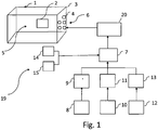
- Fig. 1 shows a schematic diagram of the arrangement 19 for ventilating the device 1.
- the device 1 includes a component 2 generating heat while performing its function and a cover 3 encapsulating the component 2.
- the cover 3 has a set of openings 4 to allow ventilation from an inside environment 5 inside of the device 1 to an outside environment 6 outside to the device 1.
- the openings 4 can be placed at one or more side of the cover 3 of the device 1. It is recommended to provide the opening 4 to at least be placed on the side of the cover 3 nearest to the component 2.
- the arrangement 19 includes means 20 for changing size of at least one of the openings 4.
- the arrangement 19 also includes a controller 7 which actuates the means 20 and changes size of at least one of the openings 4 provided on cover 3 of the device 1.
- One means 20 of the changing the size of the openings 4 can be a stretcher adapted stretch the cover 3, which is flexible, to increase or decrease size of the openings 4.
- Other means 20 for changing size of the openings 4 are illustrated in Figs. 2a-c , and Fig. 3 .
- the arrangement 19 also includes a proximity sensor 8 which senses presence of an object in proximity to the openings 4, and generates a proximity data 9.
- the controller 7 receives and processes the proximity data 9. Based on the processing of the proximity data 9, and the controller actuates the means 20 for changing size of the openings 4.
- the proximity sensor 8 is not provided, rather the user of the device 1 uses his judgement to manually handle the controller 7 to actuate the means 20 for changing the openings 4 of the cover 3.
- the arrangement 19 also includes a motion sensor 10 which senses motion of the object in proximity to the openings 4, and generates a motion data 11.
- the controller 7 receives and processes the motion data 11. Based on processing of the motion data 11, the controller 7 actuates the means 20 for changing size of the openings 4.
- the motion sensor 10 is not provided, rather the user of the device 1 uses his judgement to manually handle the controller 7 to actuate the means 20 for changing the openings 4 of the cover 3.
- the arrangement 19 also includes an environmental sensor 12 which senses at least one of environmental parameters in the outside environment 6 and generates an environmental data 13.
- the controller 7 receives and processes the environmental data 13. Based on processing of the environmental data 13, the controller 7 actuates the means 20 for changing size of the openings 4.
- the environmental sensor 12 is not provided, rather the user of the device 1 uses his judgement to manually handle the controller 7 to actuate the means 20 for changing the openings 4 of the cover 3.
- the environmental parameter can be temperature, dust, humidity, or moisture, or combination thereof.
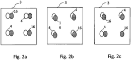
- Fig. 2a-c shows a set of movable elements 16 in coupling to the openings 4 of the cover 3.
- the set of movable elements 16 corresponds to each of the openings 4 provided on the cover 3.
- the movable elements 16 are placed in proximity to each of the openings 4.
- the movable elements 16 are in movement coupling to each of the openings 4 for covering or uncovering the openings 4.
- the movable elements 16 can move, partially or completely, to cover the openings 4, so that the size of the openings 4 is changed.
- Each of the movable elements 16 can individually be controlled for movement by the controller 7. More than one movable elements 8 can also be controlled cumulatively by the controller 7 for changing the size of the openings 4, by partially or completely covering or uncovering the movable elements 16.
- the movable elements 16 can move either around one of an axis passing through a circumference of the opening 4, or the movable elements 16 can laterally move along a diameter of the openings 4.
- the openings 4 shown in Figs. 2a-c are circular, however, the openings 4 can have any other geometry, like rectangle, square, triangle, pentagon, etc.
- the movable elements 16 are having at least size equal to or bigger than that of the size of the openings 4.
- the geometry of the movable elements 16 can be complimentary to the geometry of the openings 4.
- the geometry of the movable elements 16 can be different with respect to the geometry of the openings 4, however, the geometry of the movable elements 16 shall be such that it can cover the openings 4 completely. Fig.
- FIG. 2a shows the movable elements 16 placed in such a way, that openings 4 are completely uncovered.
- Fig. 2b shows the set of movable elements 16 partially covering the openings 4.
- the controller 7 is cumulatively controlling all the movable elements 16.
- Fig 2c shows the set of movable elements 16 partially covering some of the openings 4, uncovering some of the openings 4 completely, and completely covering remaining of the openings 6.
- the controller 7 is controlling some of the movable elements 16 individually, and some of the movable elements 16 cumulatively.
- Fig 3 shows another means for changing the size of the openings 4.
- the means are provided in form of a shutter 17.
- the shutter 17 has multiple holes 18, such that each hole 18 is corresponds to each of the opening 4.
- the shutter 17 is placed in such a way so that each of the holes 18 is in proximity to the opening 4.
- the shutter 17 is in movement coupling to the openings 4 for covering or uncovering the openings 4.
- the openings can be covered partially or completely to change size of the openings 4.
- part of the holes 18 overlaps to the openings 4 to partially cover the openings 4, while the holes 18 totally overlaps the opening to completely uncover the openings 4,
- the size of the holes 18 can be greater than or equal to size of the opening 4.
- the geometry of the holes 18 can be complimentary to the geometry of the openings 4.
- the geometry of the holes 18 can be different to that of the openings 4, however the geometry of the holes 18 should be such that to totally uncover the holes 18 when triggered by the controller.
- a plurality of openings 4 are controlled for changing the size by one shutter 17 in one go. If there are different set of openings 4 required to be managed differently, multiple shutters 17 can be provided which can individually be controlled for movement.
- Fig 4 shows a flowchart showing functioning of the arrangement.
- the proximity sensor generates the proximity data
- the environmental sensor generates the environmental data, and sends them to the controller.
- the controller compares the environmental data to the environmental threshold value, and if the environmental data is higher with respect to the environmental threshold value, moving the flow to step 104, otherwise to step 103.
- the controller compares the proximity data to the proximity threshold value, and if the proximity data is lesser than the proximity threshold value, then moving thee flow to step 104, otherwise moving the flow to step 105.
- the controller actuates the means to reduce the size of the openings, and further move the flow to step 101.
- the controller actuates the means to increase the size of the openings, and further move the flow to step 101.
- This invention can be implemented in all the devices in which there is high temperature generation inside, for example: electronic devices, automobiles, engines, etc.
- the present invention discloses an arrangement for providing ventilation from a device 1 which includes a component 2 generating heat while performing its function and a cover 3 encapsulating the component 2.
- the cover 3 comprises one or more openings 4 to allow ventilation from an inside environment 5 inside of the device 1 to an outside environment 6 outside to the device 1.
- the arrangement further includes means 20 for changing size of at least one of the openings 4, and a controller 7 which actuates the means 20 to change size of at least one of the openings 4 of the device 1.
Landscapes
- Engineering & Computer Science (AREA)
- Microelectronics & Electronic Packaging (AREA)
- Physics & Mathematics (AREA)
- Thermal Sciences (AREA)
- Ventilation (AREA)
Abstract
Description
- This invention refers to an arrangement for ventilation from a device according to
claim 1, the device according to claim 8, and a method for ventilating heat out of the device according toclaim 9. - One of the most common problems with the devices having functional components is production of heat during functioning. In electronic devices due to generation of heat, the operation of electronic circuits is affected negatively. In some cases, the high temperature on the circuits can even cause fire.
- Even though, many of such devices producing heat use a heatsink or/and a thermal conductor, however, this can still be insufficient to drive out the enough heat from the device. There should be flow of air created to drive out sufficient heat out of the device. To do that many of these devices uses holes/openings which plays as medium to create air flow out of the device. However, size, position, number of these holes are sometimes not sufficient to achieve enough cooling. On the other side, if the size of the holes is bigger, than there may be issues due to safety of human beings, or to the safety of the devices due to dust, moisture, and other environmental problems.
- Chinese Patent Publication No.
CN101370109 discloses an embedded TV radiation system which is a structural body with an impression for accepting a TV set, wherein, a first airway and a second airway communicates with the impression. The first airway leads cold air into the impression, and the second airway lead out the hot air form the inside of the impression, and common indoor air-conditioning/exhausting system is used for cooling the embedded TV set effectively thereby prolonging service life of the TV set. - Further, Japanese Patent Publication No.
JP2004364072 main body 1. - It is therefore the object of the present invention is to provide an arrangement for ventilating heat out of a device having components generating heat, however also to maintain safety of the device as well as humans/objects around the device.
- The before mentioned object is solved by an arrangement for ventilation from a device according to
claim 1, the device according to claim 8, and a method for ventilating heat out of the device according toclaim 9. - An arrangement for providing ventilation from a device comprising a component generating heat while performing its function and a cover encapsulating the component, wherein the cover comprises one or more openings to allow ventilation from an inside environment inside of the device to an outside environment outside to the device, characterized in that, the arrangement comprising means for changing size of at least one of the openings, and a controller adapted to actuate the means to change size of at least one of the openings of the device.
- This provides a mechanism for optimally ventilating out the heat out of the device. Such control of opening sizes, and further changing size of only few or all of the openings at a time, provides an optimal control for optimizing the heat flow out of the device, which may also help to ensure safety of the device, and safety of user of the device. In case, if the environmental parameters are destructive to the device in the outside environment, the size of the openings can be reduced to keep the device safe. And, if there are humans/objects around the device than the size of the openings can be reduced to keep the hums or objects safe from the heat ventilated out through the hot air flow out of the device.
- Further preferred embodiments are subject-matter of dependent claims and/or of the following specification parts.
- According to a preferred embodiment of the arrangement, the ararngement comprises a proximity sensor adapted to sense presence of an object in proximity to one or more openings, and to generate a proximity data, wherein the controller is adapted to receive and process the proximity data, and to actuate the means for changing size of one or more openings based on the proximity data.
- This embodiment is beneficial as it provides a mechanism to change the size of the openings based on proximity of a user or object near to the openings. It is important to note that, if an human being is near to the opening, in case of higher temperature of air during the heat transfer, it may lead to burn a body of the human being, and highly impact his safety. In furtherance, if a non-living object is nearby which can get affected by heat generated, such gush of hot air may severly affect it's functioning. Further, if the object or human being is in proximmity, it may also hinder the proper air flow from inside environment to the outside environment, which can affect the safety and functioning of the device too.
- According to a further preferred embodiment of the arrangement, the arrangement comprises a motion sensor adapted to sense motion of the object in proximity to one or more openings, and to generate a motion data, wherein the controller is adapted to receive and process the motion data, and to actuate the means for changing size of one or more openings based on the motion data.
- This embodiment is helpful, as it provides a reduced false positive with respect to proximity data for determining presence of the object or human being near to the openings. Also, it can also provide opportunity to keep the proximity sensor in inactive mode, untill the time motion sensor detects motion. Once the motion sensor detects the motion, the proximity sensor can be activated to sense object or human being in proximity.
- According to another embodiment of the arrangement, the arrangement comprises an environmental sensor adapted to sense at least one of environmental parameters in the inside environment, or the outside environment, or both, and to generate an environmental data, wherein the controller is adapted to receive and process the environmental data, and to actuate the means for changing size of one or more openings based on the environmental data.
- This embodiment is beneficial as it provides for mechanism to detect the environmental parameters, and based on those parameters to determine whether it is safe to widen the openings, and if it is unsafe to narrow down the openings, so as to protect the device, and further actuates the means accordingly.
- According to a further embodiment of the arrangement, the environmental parameters are at least one of a temperature, dust, humidity, or moisture, or combination thereof.
- This embodiment is helpful, as it provides for a mechanism to keep safe the device against various environmental parameters like dust, humidity, moisture, temperature, etc.
- According to a further preferred embodiment of the arrangement, the arrangement comprises a set of movable elements corresponding to each opening, the movable elements are placed in proximity to each of the openings, and each of the element is in movement coupling to each of the openings for covering or uncovering the openings, partially or completely, to change size of the openings, wherein the controller is adapted control movement of each element, either independently or cumulatively.
- This embodiment is beneficial, as it provides for mechanism to individually control each of the openings for changing its size. This embodiment is specifically useful, when the devices are big, and at a different part of device there may be a difference in environmental parameters, or at some parts the objects or human being are proximity, and to some part there is no one in proximity. In such scenario, if there are openings provided at multiple parts of the cover of the device, the size of the opening can be individually managed to ensure safety of device and objects, as well efficient heat transfer from inside environment to the outside environment.
- According to another embodiment of the arrangement, the arrangement comprises a shutter comprising multiple holes, each hole corresponds to each of the opening, the shutter is placed in such a way so that each of the holes is in proximity to the opening, the shutter is in movement coupling to the openings for covering or uncovering the openings, partially or completely, to change size of the openings, wherein the controller is adapted to control movement of the shutter to change the size of all the opening together to which it's holes are in coupling.
- This embodiment is beneficial, as it provides for mechanism to control multiple openings at a time.
- The before mentioned object is also solved by a device of claim 8. The device comprising a component generating heat while performing its function and a cover encapsulating the component, wherein the cover comprises one or more openings to allow ventilation from an inside environment inside of the device to an outside environment outside to the device, characterized in that, the device comprising the arrangement according to any of the
claims 1 to 7 - The before mentioned object is also solved by a method of
claim 9. The method for ventilating heat out of a device comprising a component generating heat while performing its function and a cover encapsulating the component, wherein the cover comprises one or more openings to allow ventilation from an inside environment inside of the device to an outside environment outside to the device, the method comprising: - actuating means for changing size of at least one of the openings of the device by a controller; and
- changing size of at least one of the openings by the means.
- According to a further preferred embodiment of the method, the method comprises receiving and processing at least one of a proximity data, a motion data, or an environmental data, or combination thereof, by the controller, wherein the proximity data relates to proximity of an object to one or more openings of the device, the motion data relates to motion of the object in proximity to one or more openings of the device, and the environmental data relates one of environmental parameters in the inside or outside environment, wherein the controller actuates the means to change size of one or more openings based on at least one of a proximity data, a motion data, or an environmental data, or combination thereof.
- According to a further preferred embodiment of the method, the method comprises steps of:
- processing the environmental data by the controller by comparing the environmental data with an environmental threshold value, and if the environmental data is more than the environmental threshold value than the controller reduces size of the openings;
- if the environmental data is less than the threshold value, processing the proximity data by the controller by comparing the proximity data with a proximity threshold value, and if the proximity data is less than the proximity threshold value, than actuating the means by the controller and reducing the size of the openings by the means, otherwise actuating the means by the controller, and depending thereon increasing size of the openings by the means.
- According to another embodiment of the method, the method comprises steps of:
- if the environmental data is less than the threshold value, than processing the motion data by the controller, and if the object is in motion, than processing the proximity data by the controller by comparing the proximity data with a proximity threshold value, and if the proximity data is less than the proximity threshold value, than actuating the means by the controller, and reducing size of the openings, otherwise actuating the means by the controller, and increasing size of the openings.
- Further benefits, goals and features of the present invention will be described by the following specification of the attached figures, in which components of the invention are exemplarily illustrated. Components of the devices and method according to the inventions, which match at least essentially with respect to their function, can be marked with the same reference sign, wherein such components do not have to be marked or described in all figures.
- The invention is just exemplarily described with respect to the attached figure in the following.
-
-
Fig. 1 illustrates a schematic diagram of an arrangement for ventilating a device. -
Fig. 2a illustrates a set of movable elements in coupling to the openings of a cover of the device, when openings are uncovered. -
Fig 2b illustrates the set of movable elements in coupling to the openings of the cover of the device, when the openings are partially covered. -
Fig 2c illustrates the set of movable elements in coupling to the openings of the cover of the device, when some openings are partially covered, some of the openings are uncovered, and remaining openings are completely covered. -
Fig 3 illustrates a shutter in coupling to the openings of the cover of the device, when some openings are partially covered. -
Fig 4 illustrates a flowchart showing functioning of the arrangement, according to one embodiment of the invention. - The present invention focuses on ventilating heat out of a device having a component which produces heat. Generally, these devices have a cover and the component is encapsulated inside the cover with minimal or no place for ventilating out the air surrounding the component. The surrounding air gets heated up due to the heat generation by the electric component. If this heat does not gets ventilated it substantially affect the functioning of the component and further the whole device. Overheating inside the device may also result in damaging the device. The invention is provided with an arrangement which helps in optimizing size of the openings provided onto the cover, so that maximum heat can be ventilated out of the device, however still keeping it safe for any user or animal moving, sitting or standing around the device, also keeping the device's component safe with respect to the environmental parameters like heat, moisture, dust, etc.
-
Fig. 1 shows a schematic diagram of thearrangement 19 for ventilating thedevice 1. Thedevice 1 includes acomponent 2 generating heat while performing its function and acover 3 encapsulating thecomponent 2. Thecover 3 has a set ofopenings 4 to allow ventilation from aninside environment 5 inside of thedevice 1 to anoutside environment 6 outside to thedevice 1. Theopenings 4 can be placed at one or more side of thecover 3 of thedevice 1. It is recommended to provide theopening 4 to at least be placed on the side of thecover 3 nearest to thecomponent 2. - The
arrangement 19 includesmeans 20 for changing size of at least one of theopenings 4. Thearrangement 19 also includes a controller 7 which actuates themeans 20 and changes size of at least one of theopenings 4 provided oncover 3 of thedevice 1. One means 20 of the changing the size of theopenings 4 can be a stretcher adapted stretch thecover 3, which is flexible, to increase or decrease size of theopenings 4. Other means 20 for changing size of theopenings 4 are illustrated inFigs. 2a-c , andFig. 3 . - The
arrangement 19 also includes a proximity sensor 8 which senses presence of an object in proximity to theopenings 4, and generates aproximity data 9. The controller 7 receives and processes theproximity data 9. Based on the processing of theproximity data 9, and the controller actuates themeans 20 for changing size of theopenings 4. In one embodiment, the proximity sensor 8 is not provided, rather the user of thedevice 1 uses his judgement to manually handle the controller 7 to actuate themeans 20 for changing theopenings 4 of thecover 3. - The
arrangement 19 also includes amotion sensor 10 which senses motion of the object in proximity to theopenings 4, and generates amotion data 11. The controller 7 receives and processes themotion data 11. Based on processing of themotion data 11, the controller 7 actuates themeans 20 for changing size of theopenings 4. In one embodiment, themotion sensor 10 is not provided, rather the user of thedevice 1 uses his judgement to manually handle the controller 7 to actuate themeans 20 for changing theopenings 4 of thecover 3. - The
arrangement 19 also includes anenvironmental sensor 12 which senses at least one of environmental parameters in theoutside environment 6 and generates anenvironmental data 13. The controller 7 receives and processes theenvironmental data 13. Based on processing of theenvironmental data 13, the controller 7 actuates themeans 20 for changing size of theopenings 4. In one embodiment, theenvironmental sensor 12 is not provided, rather the user of thedevice 1 uses his judgement to manually handle the controller 7 to actuate themeans 20 for changing theopenings 4 of thecover 3. The environmental parameter can be temperature, dust, humidity, or moisture, or combination thereof. -
Fig. 2a-c shows a set ofmovable elements 16 in coupling to theopenings 4 of thecover 3. The set ofmovable elements 16 corresponds to each of theopenings 4 provided on thecover 3. Themovable elements 16 are placed in proximity to each of theopenings 4. Themovable elements 16 are in movement coupling to each of theopenings 4 for covering or uncovering theopenings 4. Themovable elements 16 can move, partially or completely, to cover theopenings 4, so that the size of theopenings 4 is changed. Each of themovable elements 16 can individually be controlled for movement by the controller 7. More than one movable elements 8 can also be controlled cumulatively by the controller 7 for changing the size of theopenings 4, by partially or completely covering or uncovering themovable elements 16. Themovable elements 16 can move either around one of an axis passing through a circumference of theopening 4, or themovable elements 16 can laterally move along a diameter of theopenings 4. Theopenings 4 shown inFigs. 2a-c are circular, however, theopenings 4 can have any other geometry, like rectangle, square, triangle, pentagon, etc. Themovable elements 16 are having at least size equal to or bigger than that of the size of theopenings 4. The geometry of themovable elements 16 can be complimentary to the geometry of theopenings 4. The geometry of themovable elements 16 can be different with respect to the geometry of theopenings 4, however, the geometry of themovable elements 16 shall be such that it can cover theopenings 4 completely.Fig. 2a shows themovable elements 16 placed in such a way, thatopenings 4 are completely uncovered.Fig. 2b shows the set ofmovable elements 16 partially covering theopenings 4. In theFigs. 2a and 2b , the controller 7 is cumulatively controlling all themovable elements 16.Fig 2c shows the set ofmovable elements 16 partially covering some of theopenings 4, uncovering some of theopenings 4 completely, and completely covering remaining of theopenings 6. In this figure, the controller 7 is controlling some of themovable elements 16 individually, and some of themovable elements 16 cumulatively. -
Fig 3 shows another means for changing the size of theopenings 4. The means are provided in form of ashutter 17. Theshutter 17 hasmultiple holes 18, such that eachhole 18 is corresponds to each of theopening 4. Theshutter 17 is placed in such a way so that each of theholes 18 is in proximity to theopening 4. Theshutter 17 is in movement coupling to theopenings 4 for covering or uncovering theopenings 4. The openings can be covered partially or completely to change size of theopenings 4. When theshutter 17 moves, part of theholes 18 overlaps to theopenings 4 to partially cover theopenings 4, while theholes 18 totally overlaps the opening to completely uncover theopenings 4, The size of theholes 18 can be greater than or equal to size of theopening 4. The geometry of theholes 18 can be complimentary to the geometry of theopenings 4. The geometry of theholes 18 can be different to that of theopenings 4, however the geometry of theholes 18 should be such that to totally uncover theholes 18 when triggered by the controller. In this embodiment, a plurality ofopenings 4 are controlled for changing the size by oneshutter 17 in one go. If there are different set ofopenings 4 required to be managed differently,multiple shutters 17 can be provided which can individually be controlled for movement. -
Fig 4 shows a flowchart showing functioning of the arrangement. Instep 101, the proximity sensor generates the proximity data, and the environmental sensor generates the environmental data, and sends them to the controller. Instep 102, the controller compares the environmental data to the environmental threshold value, and if the environmental data is higher with respect to the environmental threshold value, moving the flow to step 104, otherwise to step 103. Instep 103, the controller compares the proximity data to the proximity threshold value, and if the proximity data is lesser than the proximity threshold value, then moving thee flow to step 104, otherwise moving the flow to step 105. Instep 104, the controller actuates the means to reduce the size of the openings, and further move the flow to step 101. Instep 105, the controller actuates the means to increase the size of the openings, and further move the flow to step 101. - This invention can be implemented in all the devices in which there is high temperature generation inside, for example: electronic devices, automobiles, engines, etc.
- Thus, the present invention discloses an arrangement for providing ventilation from a
device 1 which includes acomponent 2 generating heat while performing its function and acover 3 encapsulating thecomponent 2. Thecover 3 comprises one ormore openings 4 to allow ventilation from aninside environment 5 inside of thedevice 1 to anoutside environment 6 outside to thedevice 1. The arrangement further includesmeans 20 for changing size of at least one of theopenings 4, and a controller 7 which actuates themeans 20 to change size of at least one of theopenings 4 of thedevice 1. -
- 1
- device
- 2
- component
- 3
- cover
- 4
- openings
- 5
- inside environment
- 6
- outside environment
- 7
- controller
- 8
- proximity sensor
- 9
- proximity data
- 10
- motion sensor
- 11
- motion data
- 12
- environmental sensor
- 13
- environmental data
- 14
- environmental threshold value
- 15
- proximity threshold value
- 16
- movable elements
- 17
- shutter
- 18
- holes
- 19
- arrangement
- 20
- means for changing size of the openings
- 21
- remaining part of the opening
- 101
- Step for collecting the environmental parameter and user proximity
- 102
- Step for checking the environmental data
- 103
- Step for checking the proximity data
- 104
- Step for decreasing size of the openings
- 105
- Step for decreasing size of the openings
Claims (12)
- An arrangement (19) for providing ventilation from a device (1) comprising a component (2) generating heat while performing its function and a cover (3) encapsulating the component (2), wherein the cover (3) comprises one or more openings (4) to allow ventilation from an inside environment (5) inside of the device (1) to an outside environment (6) outside to the device (1), characterized in that, the arrangement (19) comprising:- means (20) for changing size of at least one of the openings (4); and- a controller (7) adapted to actuate the means (20) to change size of at least one of the openings (4) of the device (1).
- The arrangement (19) according to the claim 1 comprising:- a proximity sensor (8) adapted to sense presence of an object in proximity to one or more openings (4), and to generate a proximity data (9),wherein the controller (7) is adapted to receive and process the proximity data (9), and to actuate the means (20) for changing size of one or more openings (4) based on the proximity data (9).
- The arrangement (19) according to any of the claims 1 or 2 comprising:- a motion sensor (10) adapted to sense motion of the object in proximity to one or more openings (4), and to generate a motion data (11),wherein the controller (7) is adapted to receive and process the motion data (121), and to actuate the means (20) for changing size of one or more openings (4) based on the motion data (11).
- The arrangement (19) according to any of the claims 1 to 3 comprising:- an environmental sensor (12) adapted to sense at least one of environmental parameters in the inside environment (5), or the outside environment (6), or both, and to generate an environmental data (13),wherein the controller (7) is adapted to receive and process the environmental data (13), and to actuate the means (20) for changing size of one or more openings (4) based on the environmental data (13).
- The arrangement (19) according to the claim 4, wherein the environmental parameters are at least one of a temperature, dust, humidity, or moisture, or combination thereof.
- The arrangement (19) according to any of the claims 1 to 5 comprising:- a set of movable elements (16) corresponding to each opening (4), the movable elements (16) are placed in proximity to each of the openings (4), and each of the movable element (16) is in movement coupling to each of the openings (4) for covering or uncovering the openings (4), partially or completely, to change size of the openings (4), wherein the controller (7) is adapted control movement of each movable element (16), either independently or cumulatively.
- The arrangement (19) according to any of the claims 1 to 6 comprising:- a shutter (17) comprising multiple holes (18), each hole (18) corresponds to each of the opening (4), the shutter (17) is placed in such a way so that each of the holes (18) is in proximity to the opening (4), the shutter (17) is in movement coupling to the openings (4) for covering or uncovering the openings (4), partially or completely, to change size of the openings (4), wherein the controller (7) is adapted control movement of the shutter (17) to change the size of all the openings (4) together to which it's holes (18) are in coupling.
- A device (1) comprising a component (2) generating heat while performing its function and a cover (3) encapsulating the component (2), wherein the cover comprises one or more openings (4) to allow ventilation from an inside environment (5) inside of the device (1) to an outside environment (6) outside to the device (1), characterized in that, the device (1) comprising the arrangement (19) according to any of the claims 1 to 7.
- A method for ventilating heat out of a device (1) comprising a component (2) generating heat while performing its function and a cover (3) encapsulating the component (2), wherein the cover (3) comprises one or more openings (4) to allow ventilation from an inside environment (5) of the device to an outside environment (6) outside to the device (1), the method comprising:- actuating means (20) for changing size of at least one of the openings (4) of the device (1) by a controller (20); and- changing size of at least one of the openings (4) by the means (20).
- The method according to the claim 9 comprising:- receiving and processing at least one of a proximity data (9), a motion data (11), or an environmental data (13), or combination thereof, by the controller (7), wherein the proximity data (9) relates to proximity of an object to one or more openings (4) of the device (1), the motion data (11) relates to motion of the object in proximity to one or more openings (4) of the device (1), and the environmental data (13) relates one of environmental parameters in the inside environment (5) or the outside environment (6),wherein the controller (7) actuates the means (20) to change size of one or more openings (4) based on at least one of the proximity data (9), the motion data (11), or the environmental data (13), or combination thereof.
- The method according to the claim 10 comprising:- processing the environmental data (13) by the controller (7) by comparing the environmental data (13) with an environmental threshold value (14), and if the environmental data (13) is more than the environmental threshold value (14) than the controller (7) reduces size of the openings (4); and- if the environmental data (13) is less than the environmental threshold value (14), processing the proximity data (9) by the controller (7) by comparing the proximity data (9) with a proximity threshold value (15), and if the proximity data (9) is less than the proximity threshold value (15), than actuating the means (20) by the controller (7), and reducing size of the openings (4) by the means (20), otherwise actuating the means (20) by the controller (7), and increasing size of the openings (4) by the means (20).
- The method according to claim 11 comprising:- if the environmental data (13) is less than the environmental threshold value (14), than processing the motion data (11) by the controller (7), and if the object is in motion, than processing the proximity data (9) by the controller (7) by comparing the proximity data (9) with a proximity threshold value (15), and if the proximity data (9) is less than the proximity threshold value (15), than actuating the means (20) by the controller (7), and reducing size of the openings (4), otherwise actuating the means (20) by the controller (7), and increasing size of the openings (4).
Priority Applications (1)
| Application Number | Priority Date | Filing Date | Title |
|---|---|---|---|
| EP17198787.8A EP3478039B1 (en) | 2017-10-27 | 2017-10-27 | Arrangement for ventilating heat out of a device |
Applications Claiming Priority (1)
| Application Number | Priority Date | Filing Date | Title |
|---|---|---|---|
| EP17198787.8A EP3478039B1 (en) | 2017-10-27 | 2017-10-27 | Arrangement for ventilating heat out of a device |
Publications (2)
| Publication Number | Publication Date |
|---|---|
| EP3478039A1 true EP3478039A1 (en) | 2019-05-01 |
| EP3478039B1 EP3478039B1 (en) | 2021-01-06 |
Family
ID=60262721
Family Applications (1)
| Application Number | Title | Priority Date | Filing Date |
|---|---|---|---|
| EP17198787.8A Active EP3478039B1 (en) | 2017-10-27 | 2017-10-27 | Arrangement for ventilating heat out of a device |
Country Status (1)
| Country | Link |
|---|---|
| EP (1) | EP3478039B1 (en) |
Citations (4)
| Publication number | Priority date | Publication date | Assignee | Title |
|---|---|---|---|---|
| JP2004364072A (en) | 2003-06-06 | 2004-12-24 | Funai Electric Co Ltd | Tv receiver, and display device |
| US20050241810A1 (en) * | 2004-04-29 | 2005-11-03 | Hewlett-Packard Development Company, L.P. | Controllable flow resistance in a cooling apparatus |
| CN101370109A (en) | 2007-08-16 | 2009-02-18 | 纬创资通股份有限公司 | Embedded television heat dissipation system |
| US9735083B1 (en) * | 2016-04-18 | 2017-08-15 | International Business Machines Corporation | Adjustable heat sink fin spacing |
-
2017
- 2017-10-27 EP EP17198787.8A patent/EP3478039B1/en active Active
Patent Citations (4)
| Publication number | Priority date | Publication date | Assignee | Title |
|---|---|---|---|---|
| JP2004364072A (en) | 2003-06-06 | 2004-12-24 | Funai Electric Co Ltd | Tv receiver, and display device |
| US20050241810A1 (en) * | 2004-04-29 | 2005-11-03 | Hewlett-Packard Development Company, L.P. | Controllable flow resistance in a cooling apparatus |
| CN101370109A (en) | 2007-08-16 | 2009-02-18 | 纬创资通股份有限公司 | Embedded television heat dissipation system |
| US9735083B1 (en) * | 2016-04-18 | 2017-08-15 | International Business Machines Corporation | Adjustable heat sink fin spacing |
Also Published As
| Publication number | Publication date |
|---|---|
| EP3478039B1 (en) | 2021-01-06 |
Similar Documents
| Publication | Publication Date | Title |
|---|---|---|
| US11904651B2 (en) | Method for operating a ventilation device, ventilation device, charging device with a ventilation device and motor vehicle | |
| US20190309968A1 (en) | Thermal management system with thermographic sensing | |
| EP0746192A1 (en) | Protective casing structure for electronic apparatus | |
| US20050241810A1 (en) | Controllable flow resistance in a cooling apparatus | |
| JP2016133303A5 (en) | ||
| CN105318487B (en) | Air-conditioner control method and air conditioner control system | |
| CN109595758A (en) | Control method, device and the air conditioner with it of air conditioner | |
| CN109945385A (en) | Heat dissipation control method and heat dissipation structure of electric appliance box capable of achieving stable heat dissipation and air conditioner | |
| EP4329449A1 (en) | Heating control method and apparatus of electric control box, and air conditioner | |
| EP3478039B1 (en) | Arrangement for ventilating heat out of a device | |
| JP2009014259A (en) | Air conditioner | |
| KR20200068471A (en) | Temperature control system for station of mobile telecomunication and the method | |
| CN208999853U (en) | A kind of small drone cabin temperature control system | |
| CN107238172A (en) | The energy-saving control method and house system of house system | |
| JP2011029341A (en) | Electronic apparatus cooling system, electronic apparatus cooling method and program | |
| US5252030A (en) | Automatic operation apparatus for ventilating fan | |
| CN213141087U (en) | Install novel mixed cooling system of elevator additional | |
| JPH0517560Y2 (en) | ||
| EP4656948A1 (en) | Cooking appliance with digital controller door and method for enhancing voice recognition performance | |
| KR101644452B1 (en) | Air conditionig state display apparatus | |
| US20070160481A1 (en) | Control scheme for a roof vent fan assembly | |
| KR20250172331A (en) | Cooking appliance with digital controller door and method of enhancing voice recognition performance | |
| KR101439647B1 (en) | Apparatus for defrosting air conditioner of vehicle and method thereof | |
| US20250374389A1 (en) | Cooking appliance with digital controller door and method for controlling power-off of cooking appliance | |
| US6939220B1 (en) | Control structure fastened with the housing of an electronic device for regulating a cooler of the electronic device |
Legal Events
| Date | Code | Title | Description |
|---|---|---|---|
| PUAI | Public reference made under article 153(3) epc to a published international application that has entered the european phase |
Free format text: ORIGINAL CODE: 0009012 |
|
| STAA | Information on the status of an ep patent application or granted ep patent |
Free format text: STATUS: THE APPLICATION HAS BEEN PUBLISHED |
|
| AK | Designated contracting states |
Kind code of ref document: A1 Designated state(s): AL AT BE BG CH CY CZ DE DK EE ES FI FR GB GR HR HU IE IS IT LI LT LU LV MC MK MT NL NO PL PT RO RS SE SI SK SM TR |
|
| AX | Request for extension of the european patent |
Extension state: BA ME |
|
| STAA | Information on the status of an ep patent application or granted ep patent |
Free format text: STATUS: REQUEST FOR EXAMINATION WAS MADE |
|
| 17P | Request for examination filed |
Effective date: 20191104 |
|
| RBV | Designated contracting states (corrected) |
Designated state(s): AL AT BE BG CH CY CZ DE DK EE ES FI FR GB GR HR HU IE IS IT LI LT LU LV MC MK MT NL NO PL PT RO RS SE SI SK SM TR |
|
| GRAP | Despatch of communication of intention to grant a patent |
Free format text: ORIGINAL CODE: EPIDOSNIGR1 |
|
| STAA | Information on the status of an ep patent application or granted ep patent |
Free format text: STATUS: GRANT OF PATENT IS INTENDED |
|
| INTG | Intention to grant announced |
Effective date: 20200730 |
|
| GRAS | Grant fee paid |
Free format text: ORIGINAL CODE: EPIDOSNIGR3 |
|
| GRAA | (expected) grant |
Free format text: ORIGINAL CODE: 0009210 |
|
| STAA | Information on the status of an ep patent application or granted ep patent |
Free format text: STATUS: THE PATENT HAS BEEN GRANTED |
|
| AK | Designated contracting states |
Kind code of ref document: B1 Designated state(s): AL AT BE BG CH CY CZ DE DK EE ES FI FR GB GR HR HU IE IS IT LI LT LU LV MC MK MT NL NO PL PT RO RS SE SI SK SM TR |
|
| REG | Reference to a national code |
Ref country code: GB Ref legal event code: FG4D |
|
| REG | Reference to a national code |
Ref country code: AT Ref legal event code: REF Ref document number: 1353786 Country of ref document: AT Kind code of ref document: T Effective date: 20210115 Ref country code: CH Ref legal event code: EP |
|
| REG | Reference to a national code |
Ref country code: DE Ref legal event code: R096 Ref document number: 602017030823 Country of ref document: DE |
|
| REG | Reference to a national code |
Ref country code: IE Ref legal event code: FG4D |
|
| REG | Reference to a national code |
Ref country code: NL Ref legal event code: MP Effective date: 20210106 |
|
| REG | Reference to a national code |
Ref country code: AT Ref legal event code: MK05 Ref document number: 1353786 Country of ref document: AT Kind code of ref document: T Effective date: 20210106 |
|
| REG | Reference to a national code |
Ref country code: LT Ref legal event code: MG9D |
|
| PG25 | Lapsed in a contracting state [announced via postgrant information from national office to epo] |
Ref country code: GR Free format text: LAPSE BECAUSE OF FAILURE TO SUBMIT A TRANSLATION OF THE DESCRIPTION OR TO PAY THE FEE WITHIN THE PRESCRIBED TIME-LIMIT Effective date: 20210407 Ref country code: HR Free format text: LAPSE BECAUSE OF FAILURE TO SUBMIT A TRANSLATION OF THE DESCRIPTION OR TO PAY THE FEE WITHIN THE PRESCRIBED TIME-LIMIT Effective date: 20210106 Ref country code: FI Free format text: LAPSE BECAUSE OF FAILURE TO SUBMIT A TRANSLATION OF THE DESCRIPTION OR TO PAY THE FEE WITHIN THE PRESCRIBED TIME-LIMIT Effective date: 20210106 Ref country code: PT Free format text: LAPSE BECAUSE OF FAILURE TO SUBMIT A TRANSLATION OF THE DESCRIPTION OR TO PAY THE FEE WITHIN THE PRESCRIBED TIME-LIMIT Effective date: 20210506 Ref country code: NO Free format text: LAPSE BECAUSE OF FAILURE TO SUBMIT A TRANSLATION OF THE DESCRIPTION OR TO PAY THE FEE WITHIN THE PRESCRIBED TIME-LIMIT Effective date: 20210406 Ref country code: BG Free format text: LAPSE BECAUSE OF FAILURE TO SUBMIT A TRANSLATION OF THE DESCRIPTION OR TO PAY THE FEE WITHIN THE PRESCRIBED TIME-LIMIT Effective date: 20210406 Ref country code: LT Free format text: LAPSE BECAUSE OF FAILURE TO SUBMIT A TRANSLATION OF THE DESCRIPTION OR TO PAY THE FEE WITHIN THE PRESCRIBED TIME-LIMIT Effective date: 20210106 |
|
| PG25 | Lapsed in a contracting state [announced via postgrant information from national office to epo] |
Ref country code: RS Free format text: LAPSE BECAUSE OF FAILURE TO SUBMIT A TRANSLATION OF THE DESCRIPTION OR TO PAY THE FEE WITHIN THE PRESCRIBED TIME-LIMIT Effective date: 20210106 Ref country code: PL Free format text: LAPSE BECAUSE OF FAILURE TO SUBMIT A TRANSLATION OF THE DESCRIPTION OR TO PAY THE FEE WITHIN THE PRESCRIBED TIME-LIMIT Effective date: 20210106 Ref country code: LV Free format text: LAPSE BECAUSE OF FAILURE TO SUBMIT A TRANSLATION OF THE DESCRIPTION OR TO PAY THE FEE WITHIN THE PRESCRIBED TIME-LIMIT Effective date: 20210106 Ref country code: AT Free format text: LAPSE BECAUSE OF FAILURE TO SUBMIT A TRANSLATION OF THE DESCRIPTION OR TO PAY THE FEE WITHIN THE PRESCRIBED TIME-LIMIT Effective date: 20210106 Ref country code: SE Free format text: LAPSE BECAUSE OF FAILURE TO SUBMIT A TRANSLATION OF THE DESCRIPTION OR TO PAY THE FEE WITHIN THE PRESCRIBED TIME-LIMIT Effective date: 20210106 |
|
| PG25 | Lapsed in a contracting state [announced via postgrant information from national office to epo] |
Ref country code: IS Free format text: LAPSE BECAUSE OF FAILURE TO SUBMIT A TRANSLATION OF THE DESCRIPTION OR TO PAY THE FEE WITHIN THE PRESCRIBED TIME-LIMIT Effective date: 20210506 |
|
| REG | Reference to a national code |
Ref country code: DE Ref legal event code: R097 Ref document number: 602017030823 Country of ref document: DE |
|
| PG25 | Lapsed in a contracting state [announced via postgrant information from national office to epo] |
Ref country code: EE Free format text: LAPSE BECAUSE OF FAILURE TO SUBMIT A TRANSLATION OF THE DESCRIPTION OR TO PAY THE FEE WITHIN THE PRESCRIBED TIME-LIMIT Effective date: 20210106 Ref country code: CZ Free format text: LAPSE BECAUSE OF FAILURE TO SUBMIT A TRANSLATION OF THE DESCRIPTION OR TO PAY THE FEE WITHIN THE PRESCRIBED TIME-LIMIT Effective date: 20210106 Ref country code: SM Free format text: LAPSE BECAUSE OF FAILURE TO SUBMIT A TRANSLATION OF THE DESCRIPTION OR TO PAY THE FEE WITHIN THE PRESCRIBED TIME-LIMIT Effective date: 20210106 |
|
| PLBE | No opposition filed within time limit |
Free format text: ORIGINAL CODE: 0009261 |
|
| STAA | Information on the status of an ep patent application or granted ep patent |
Free format text: STATUS: NO OPPOSITION FILED WITHIN TIME LIMIT |
|
| PG25 | Lapsed in a contracting state [announced via postgrant information from national office to epo] |
Ref country code: DK Free format text: LAPSE BECAUSE OF FAILURE TO SUBMIT A TRANSLATION OF THE DESCRIPTION OR TO PAY THE FEE WITHIN THE PRESCRIBED TIME-LIMIT Effective date: 20210106 Ref country code: RO Free format text: LAPSE BECAUSE OF FAILURE TO SUBMIT A TRANSLATION OF THE DESCRIPTION OR TO PAY THE FEE WITHIN THE PRESCRIBED TIME-LIMIT Effective date: 20210106 Ref country code: SK Free format text: LAPSE BECAUSE OF FAILURE TO SUBMIT A TRANSLATION OF THE DESCRIPTION OR TO PAY THE FEE WITHIN THE PRESCRIBED TIME-LIMIT Effective date: 20210106 |
|
| 26N | No opposition filed |
Effective date: 20211007 |
|
| PG25 | Lapsed in a contracting state [announced via postgrant information from national office to epo] |
Ref country code: AL Free format text: LAPSE BECAUSE OF FAILURE TO SUBMIT A TRANSLATION OF THE DESCRIPTION OR TO PAY THE FEE WITHIN THE PRESCRIBED TIME-LIMIT Effective date: 20210106 Ref country code: ES Free format text: LAPSE BECAUSE OF FAILURE TO SUBMIT A TRANSLATION OF THE DESCRIPTION OR TO PAY THE FEE WITHIN THE PRESCRIBED TIME-LIMIT Effective date: 20210106 |
|
| PG25 | Lapsed in a contracting state [announced via postgrant information from national office to epo] |
Ref country code: SI Free format text: LAPSE BECAUSE OF FAILURE TO SUBMIT A TRANSLATION OF THE DESCRIPTION OR TO PAY THE FEE WITHIN THE PRESCRIBED TIME-LIMIT Effective date: 20210106 |
|
| PG25 | Lapsed in a contracting state [announced via postgrant information from national office to epo] |
Ref country code: IT Free format text: LAPSE BECAUSE OF FAILURE TO SUBMIT A TRANSLATION OF THE DESCRIPTION OR TO PAY THE FEE WITHIN THE PRESCRIBED TIME-LIMIT Effective date: 20210106 |
|
| REG | Reference to a national code |
Ref country code: CH Ref legal event code: PL |
|
| PG25 | Lapsed in a contracting state [announced via postgrant information from national office to epo] |
Ref country code: IS Free format text: LAPSE BECAUSE OF FAILURE TO SUBMIT A TRANSLATION OF THE DESCRIPTION OR TO PAY THE FEE WITHIN THE PRESCRIBED TIME-LIMIT Effective date: 20210506 |
|
| REG | Reference to a national code |
Ref country code: BE Ref legal event code: MM Effective date: 20211031 |
|
| PG25 | Lapsed in a contracting state [announced via postgrant information from national office to epo] |
Ref country code: MC Free format text: LAPSE BECAUSE OF FAILURE TO SUBMIT A TRANSLATION OF THE DESCRIPTION OR TO PAY THE FEE WITHIN THE PRESCRIBED TIME-LIMIT Effective date: 20210106 |
|
| PG25 | Lapsed in a contracting state [announced via postgrant information from national office to epo] |
Ref country code: LU Free format text: LAPSE BECAUSE OF NON-PAYMENT OF DUE FEES Effective date: 20211027 Ref country code: BE Free format text: LAPSE BECAUSE OF NON-PAYMENT OF DUE FEES Effective date: 20211031 |
|
| PG25 | Lapsed in a contracting state [announced via postgrant information from national office to epo] |
Ref country code: LI Free format text: LAPSE BECAUSE OF NON-PAYMENT OF DUE FEES Effective date: 20211031 Ref country code: CH Free format text: LAPSE BECAUSE OF NON-PAYMENT OF DUE FEES Effective date: 20211031 |
|
| PG25 | Lapsed in a contracting state [announced via postgrant information from national office to epo] |
Ref country code: FR Free format text: LAPSE BECAUSE OF NON-PAYMENT OF DUE FEES Effective date: 20211031 |
|
| PG25 | Lapsed in a contracting state [announced via postgrant information from national office to epo] |
Ref country code: IE Free format text: LAPSE BECAUSE OF NON-PAYMENT OF DUE FEES Effective date: 20211027 |
|
| PG25 | Lapsed in a contracting state [announced via postgrant information from national office to epo] |
Ref country code: NL Free format text: LAPSE BECAUSE OF NON-PAYMENT OF DUE FEES Effective date: 20210206 Ref country code: CY Free format text: LAPSE BECAUSE OF FAILURE TO SUBMIT A TRANSLATION OF THE DESCRIPTION OR TO PAY THE FEE WITHIN THE PRESCRIBED TIME-LIMIT Effective date: 20210106 |
|
| PG25 | Lapsed in a contracting state [announced via postgrant information from national office to epo] |
Ref country code: HU Free format text: LAPSE BECAUSE OF FAILURE TO SUBMIT A TRANSLATION OF THE DESCRIPTION OR TO PAY THE FEE WITHIN THE PRESCRIBED TIME-LIMIT; INVALID AB INITIO Effective date: 20171027 |
|
| PGFP | Annual fee paid to national office [announced via postgrant information from national office to epo] |
Ref country code: GB Payment date: 20231020 Year of fee payment: 7 |
|
| PGFP | Annual fee paid to national office [announced via postgrant information from national office to epo] |
Ref country code: DE Payment date: 20231020 Year of fee payment: 7 |
|
| PG25 | Lapsed in a contracting state [announced via postgrant information from national office to epo] |
Ref country code: MK Free format text: LAPSE BECAUSE OF FAILURE TO SUBMIT A TRANSLATION OF THE DESCRIPTION OR TO PAY THE FEE WITHIN THE PRESCRIBED TIME-LIMIT Effective date: 20210106 |
|
| PG25 | Lapsed in a contracting state [announced via postgrant information from national office to epo] |
Ref country code: MT Free format text: LAPSE BECAUSE OF FAILURE TO SUBMIT A TRANSLATION OF THE DESCRIPTION OR TO PAY THE FEE WITHIN THE PRESCRIBED TIME-LIMIT Effective date: 20210106 |
|
| REG | Reference to a national code |
Ref country code: DE Ref legal event code: R119 Ref document number: 602017030823 Country of ref document: DE |
|
| GBPC | Gb: european patent ceased through non-payment of renewal fee |
Effective date: 20241027 |
|
| PG25 | Lapsed in a contracting state [announced via postgrant information from national office to epo] |
Ref country code: DE Free format text: LAPSE BECAUSE OF NON-PAYMENT OF DUE FEES Effective date: 20250501 |
|
| PG25 | Lapsed in a contracting state [announced via postgrant information from national office to epo] |
Ref country code: GB Free format text: LAPSE BECAUSE OF NON-PAYMENT OF DUE FEES Effective date: 20241027 |
|
| PGFP | Annual fee paid to national office [announced via postgrant information from national office to epo] |
Ref country code: TR Payment date: 20251027 Year of fee payment: 9 |