EP3477604A1 - Sheet processing apparatus - Google Patents
Sheet processing apparatus Download PDFInfo
- Publication number
- EP3477604A1 EP3477604A1 EP18203251.6A EP18203251A EP3477604A1 EP 3477604 A1 EP3477604 A1 EP 3477604A1 EP 18203251 A EP18203251 A EP 18203251A EP 3477604 A1 EP3477604 A1 EP 3477604A1
- Authority
- EP
- European Patent Office
- Prior art keywords
- sheet
- section
- storage
- processing apparatus
- transporter
- Prior art date
- Legal status (The legal status is an assumption and is not a legal conclusion. Google has not performed a legal analysis and makes no representation as to the accuracy of the status listed.)
- Granted
Links
Images

Classifications
-
- B—PERFORMING OPERATIONS; TRANSPORTING
- B65—CONVEYING; PACKING; STORING; HANDLING THIN OR FILAMENTARY MATERIAL
- B65H—HANDLING THIN OR FILAMENTARY MATERIAL, e.g. SHEETS, WEBS, CABLES
- B65H29/00—Delivering or advancing articles from machines; Advancing articles to or into piles
- B65H29/58—Article switches or diverters
-
- B—PERFORMING OPERATIONS; TRANSPORTING
- B65—CONVEYING; PACKING; STORING; HANDLING THIN OR FILAMENTARY MATERIAL
- B65H—HANDLING THIN OR FILAMENTARY MATERIAL, e.g. SHEETS, WEBS, CABLES
- B65H29/00—Delivering or advancing articles from machines; Advancing articles to or into piles
- B65H29/58—Article switches or diverters
- B65H29/60—Article switches or diverters diverting the stream into alternative paths
-
- B—PERFORMING OPERATIONS; TRANSPORTING
- B65—CONVEYING; PACKING; STORING; HANDLING THIN OR FILAMENTARY MATERIAL
- B65H—HANDLING THIN OR FILAMENTARY MATERIAL, e.g. SHEETS, WEBS, CABLES
- B65H29/00—Delivering or advancing articles from machines; Advancing articles to or into piles
- B65H29/006—Winding articles into rolls
-
- B—PERFORMING OPERATIONS; TRANSPORTING
- B65—CONVEYING; PACKING; STORING; HANDLING THIN OR FILAMENTARY MATERIAL
- B65H—HANDLING THIN OR FILAMENTARY MATERIAL, e.g. SHEETS, WEBS, CABLES
- B65H29/00—Delivering or advancing articles from machines; Advancing articles to or into piles
- B65H29/12—Delivering or advancing articles from machines; Advancing articles to or into piles by means of the nip between two, or between two sets of, moving tapes or bands or rollers
- B65H29/125—Delivering or advancing articles from machines; Advancing articles to or into piles by means of the nip between two, or between two sets of, moving tapes or bands or rollers between two sets of rollers
-
- B—PERFORMING OPERATIONS; TRANSPORTING
- B65—CONVEYING; PACKING; STORING; HANDLING THIN OR FILAMENTARY MATERIAL
- B65H—HANDLING THIN OR FILAMENTARY MATERIAL, e.g. SHEETS, WEBS, CABLES
- B65H31/00—Pile receivers
- B65H31/02—Pile receivers with stationary end support against which pile accumulates
-
- B—PERFORMING OPERATIONS; TRANSPORTING
- B65—CONVEYING; PACKING; STORING; HANDLING THIN OR FILAMENTARY MATERIAL
- B65H—HANDLING THIN OR FILAMENTARY MATERIAL, e.g. SHEETS, WEBS, CABLES
- B65H39/00—Associating, collating, or gathering articles or webs
- B65H39/10—Associating articles from a single source, to form, e.g. a writing-pad
- B65H39/115—Associating articles from a single source, to form, e.g. a writing-pad in juxtaposed carriers
-
- B—PERFORMING OPERATIONS; TRANSPORTING
- B65—CONVEYING; PACKING; STORING; HANDLING THIN OR FILAMENTARY MATERIAL
- B65H—HANDLING THIN OR FILAMENTARY MATERIAL, e.g. SHEETS, WEBS, CABLES
- B65H5/00—Feeding articles separated from piles; Feeding articles to machines
- B65H5/06—Feeding articles separated from piles; Feeding articles to machines by rollers or balls, e.g. between rollers
-
- G—PHYSICS
- G07—CHECKING-DEVICES
- G07D—HANDLING OF COINS OR VALUABLE PAPERS, e.g. TESTING, SORTING BY DENOMINATIONS, COUNTING, DISPENSING, CHANGING OR DEPOSITING
- G07D11/00—Devices accepting coins; Devices accepting, dispensing, sorting or counting valuable papers
- G07D11/10—Mechanical details
- G07D11/16—Handling of valuable papers
- G07D11/18—Diverting into different paths or containers
-
- G—PHYSICS
- G07—CHECKING-DEVICES
- G07D—HANDLING OF COINS OR VALUABLE PAPERS, e.g. TESTING, SORTING BY DENOMINATIONS, COUNTING, DISPENSING, CHANGING OR DEPOSITING
- G07D11/00—Devices accepting coins; Devices accepting, dispensing, sorting or counting valuable papers
- G07D11/40—Device architecture, e.g. modular construction
-
- G—PHYSICS
- G07—CHECKING-DEVICES
- G07D—HANDLING OF COINS OR VALUABLE PAPERS, e.g. TESTING, SORTING BY DENOMINATIONS, COUNTING, DISPENSING, CHANGING OR DEPOSITING
- G07D11/00—Devices accepting coins; Devices accepting, dispensing, sorting or counting valuable papers
- G07D11/50—Sorting or counting valuable papers
-
- B—PERFORMING OPERATIONS; TRANSPORTING
- B65—CONVEYING; PACKING; STORING; HANDLING THIN OR FILAMENTARY MATERIAL
- B65H—HANDLING THIN OR FILAMENTARY MATERIAL, e.g. SHEETS, WEBS, CABLES
- B65H2301/00—Handling processes for sheets or webs
- B65H2301/40—Type of handling process
- B65H2301/41—Winding, unwinding
- B65H2301/419—Winding, unwinding from or to storage, i.e. the storage integrating winding or unwinding means
- B65H2301/4191—Winding, unwinding from or to storage, i.e. the storage integrating winding or unwinding means for handling articles of limited length, e.g. AO format, arranged at intervals from each other
- B65H2301/41912—Winding, unwinding from or to storage, i.e. the storage integrating winding or unwinding means for handling articles of limited length, e.g. AO format, arranged at intervals from each other between two belt like members
-
- B—PERFORMING OPERATIONS; TRANSPORTING
- B65—CONVEYING; PACKING; STORING; HANDLING THIN OR FILAMENTARY MATERIAL
- B65H—HANDLING THIN OR FILAMENTARY MATERIAL, e.g. SHEETS, WEBS, CABLES
- B65H2301/00—Handling processes for sheets or webs
- B65H2301/40—Type of handling process
- B65H2301/42—Piling, depiling, handling piles
- B65H2301/421—Forming a pile
- B65H2301/4212—Forming a pile of articles substantially horizontal
-
- B—PERFORMING OPERATIONS; TRANSPORTING
- B65—CONVEYING; PACKING; STORING; HANDLING THIN OR FILAMENTARY MATERIAL
- B65H—HANDLING THIN OR FILAMENTARY MATERIAL, e.g. SHEETS, WEBS, CABLES
- B65H2402/00—Constructional details of the handling apparatus
- B65H2402/40—Details of frames, housings or mountings of the whole handling apparatus
- B65H2402/45—Doors
-
- B—PERFORMING OPERATIONS; TRANSPORTING
- B65—CONVEYING; PACKING; STORING; HANDLING THIN OR FILAMENTARY MATERIAL
- B65H—HANDLING THIN OR FILAMENTARY MATERIAL, e.g. SHEETS, WEBS, CABLES
- B65H2404/00—Parts for transporting or guiding the handled material
- B65H2404/60—Other elements in face contact with handled material
- B65H2404/63—Oscillating, pivoting around an axis parallel to face of material, e.g. diverting means
- B65H2404/632—Wedge member
-
- B—PERFORMING OPERATIONS; TRANSPORTING
- B65—CONVEYING; PACKING; STORING; HANDLING THIN OR FILAMENTARY MATERIAL
- B65H—HANDLING THIN OR FILAMENTARY MATERIAL, e.g. SHEETS, WEBS, CABLES
- B65H2405/00—Parts for holding the handled material
- B65H2405/10—Cassettes, holders, bins, decks, trays, supports or magazines for sheets stacked substantially horizontally
- B65H2405/11—Parts and details thereof
- B65H2405/111—Bottom
- B65H2405/1115—Bottom with surface inclined, e.g. in width-wise direction
- B65H2405/11151—Bottom with surface inclined, e.g. in width-wise direction with surface inclined upwardly in transport direction
-
- B—PERFORMING OPERATIONS; TRANSPORTING
- B65—CONVEYING; PACKING; STORING; HANDLING THIN OR FILAMENTARY MATERIAL
- B65H—HANDLING THIN OR FILAMENTARY MATERIAL, e.g. SHEETS, WEBS, CABLES
- B65H2407/00—Means not provided for in groups B65H2220/00 – B65H2406/00 specially adapted for particular purposes
- B65H2407/30—Means for preventing damage of handled material, e.g. by controlling atmosphere
-
- B—PERFORMING OPERATIONS; TRANSPORTING
- B65—CONVEYING; PACKING; STORING; HANDLING THIN OR FILAMENTARY MATERIAL
- B65H—HANDLING THIN OR FILAMENTARY MATERIAL, e.g. SHEETS, WEBS, CABLES
- B65H2601/00—Problem to be solved or advantage achieved
- B65H2601/50—Diminishing, minimizing or reducing
- B65H2601/52—Diminishing, minimizing or reducing entities relating to handling machine
- B65H2601/523—Required space
-
- B—PERFORMING OPERATIONS; TRANSPORTING
- B65—CONVEYING; PACKING; STORING; HANDLING THIN OR FILAMENTARY MATERIAL
- B65H—HANDLING THIN OR FILAMENTARY MATERIAL, e.g. SHEETS, WEBS, CABLES
- B65H2701/00—Handled material; Storage means
- B65H2701/10—Handled articles or webs
- B65H2701/19—Specific article or web
- B65H2701/1912—Banknotes, bills and cheques or the like
Definitions
- the present invention relates to a sheet processing apparatus that stores and ejects sheets.
- a cash handling apparatus that receives cash, such as banknotes, according to the content of a transaction with a customer, counts and stores the received cash, and dispenses the stored cash according to the count result (e.g., see PTL1).
- Such a cash handling apparatus is required by a user to be reduced in size in consideration of the installation space.
- An object of the present invention is to provide a sheet processing apparatus that securely achieves the operability, handling property, and amount of storage that are analogous to those of the conventional art, while facilitating reduction in the size of the apparatus.
- a sheet processing apparatus of the present invention includes: an input section that receives a sheet; a dispensing section that dispenses the sheet; a transporter that transports the sheet input through the input section to the dispensing section; a storage that stores the sheet; and a diverting section that diverts the sheet transported by the transporter to the storage, in which a diversion point at which the sheet is diverted by the diverting section is provided at a position higher than a terminal end of the transporter.
- the sheet processing apparatus of the present invention can securely achieve the operability, handling property, and amount of storage that are analogous to those of the conventional art, while facilitating reduction in the size of the apparatus.
- FIG. 1 is a left side sectional view illustrating a sheet processing apparatus according to the embodiment of the present invention.
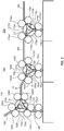
- FIG. 2 is an enlarged left side sectional view around a first diverting section, a second diverting section, and a third diverting section.
- the sheet processing apparatus 10 includes a housing 20, an input section 100 provided on one side of the housing 20, a dispensing section 190 provided on the one side of the housing 20 and below the input section 100, and a shutter 200 that covers the dispensing section 190.
- the sheet processing apparatus 10 internally includes a first transporter 120 that transports a sheet to the other side, a turning-back section 125 that changes the transport direction from that toward the other side to that toward the one side, and a second transporter 135, a third transporter 140, a fourth transporter 160, a fifth transporter 180 and a sixth transporter 240 that transport the sheet to the one side.
- the sheet processing apparatus 10 internally includes a first storage 250, a second storage 210, a third storage 220 and a fourth storage 230 that store sheets.
- the sheet processing apparatus 10 includes a first diverting section 130, a second diverting section 150 and a third diverting section 170 that divert the sheet.
- the sheet processing apparatus 10 includes a control section (not illustrated) that controls the operation of each element.
- the first transporter 120 constitutes a first transport path section.
- the second transporter 135, the third transporter 140, the fourth transporter 160 and the fifth transporter 180 constitute a second transport path section.
- the one side or the first side is a side where the input section 100 and the dispensing section 190 are provided.
- the side where the input section 100 and the dispensing section 190 are provided is called a front surface side.
- the other side or the second side is a side opposite to the one side.
- the side opposite to the one side is called a rear surface side.
- the left direction of the sheet processing apparatus 10 viewed from the front surface side is called a left side.
- the direction from the one side (first side) to the other side (second side) is called a first direction.
- the housing 20 has a box shape for storing each element, and includes the input section 100 and the dispensing section 190 on the front surface side.
- the housing 20 of the sheet processing apparatus 10 according to the embodiment of the present invention is formed to have a desktop size mountable on a table or the like.
- the input section 100 is a receiving section for receiving input sheets. At the input section 100, an inlet is formed. A user inputs sheets through the inlet into the sheet processing apparatus 10.
- the input section 100 may be configured to receive sheets to be input one-by-one, or to receive multiple sheets collectively.
- the first transporter 120 is a transport path for transporting the sheet input through the input section 100, to the rear surface side.
- the first transporter 120 transports the sheet fed by a pair of rollers provided above and below the first transporter 120.
- the first transporter 120 transports the sheet fed by a pair of endless belts (not illustrated) provided above and below the first transporter 120.
- the endless belts are wound around multiple rollers (not illustrated). At least one roller among the rollers is rotatably driven. The driving force is transmitted to the endless belts, thereby rotating the endless belts.
- FIG. 1 illustrates the mode where the first transporter 120 is formed to be bent multiple times in the vertical direction.
- the first transporter 120 may be linearly formed.
- a recognition unit 110 is a recognition unit that recognizes the sheet input through the input section 100.
- the recognition unit 110 is provided at a position (a position in the first direction viewed from the input section 100) of the middle of the first transporter 120 (first transport path section) on the rear surface side of the input section 100.
- the second transport path section resides below this position.
- the second transport path section is oriented toward a lower position as the path approaches the front surface side. Accordingly, the position is accompanied by a relatively large space. Consequently, by disposing the recognition unit 110 having a relatively large size at the position, the entire height of the sheet processing apparatus 10 can be reduced.
- the recognition unit 110 includes sensors, such as an image sensor and a magnetic sensor.
- the recognition unit 110 further includes a memory section, such as a memory.
- the recognition unit 110 compares information on the sheet read by the sensor with the information about the sheet stored in the memory section, and determines the type, the authenticity, damage and dirtiness and the like of the sheet.
- the control section determines the storage where the sheet is to be stored among the second storage 210, the third storage 220 and the fourth storage 230, on the basis of the result of the determination of the type of the sheet by the recognition unit 110.
- the control section controls each section to store the sheet, as a sheet to be rejected, in the first storage 250.
- the sheet stored in the first storage 250 is collected by the user or the like of the sheet processing apparatus 10.
- the turning-back section 125 is a transport path for changing the transport direction of the sheet transported on the rear surface side by the first transporter 120 to the front surface side.
- the turning-back section 125 is formed to have a circular-arc shape, and its one end is connected to the first transporter 120 and the other end is connected to the second transporter 135.
- the shape of the turning-back section 125 is not limited to the circular-arc shape.
- the turning-back section 125 may include a linearly formed transport path.
- the turning-back section 125 may include a circular-arc-shaped transport path for changing, downward, the direction of the transport path oriented toward the rear surface side, a transport path formed linearly downward, and a circular-arc-shaped transport path for changing the direction of the transport path formed downward, to the front surface side.
- the second transporter 135, the third transporter 140, the fourth transporter 160 and the fifth transporter 180 are transport paths for transporting, to the dispensing section 190, the sheet whose transport direction has been changed from that to the rear to that to the front at the turning-back section 125; the dispensing section 190 is disposed on the front surface side.
- the second transporter 135 is a transport path that has one end connected to the turning-back section 125 and is formed obliquely downward and frontward from the turning-back section 125.
- the first diverting section 130 is connected to the other end of the second transporter 135.
- the third transporter 140 includes a transport path that has one end connected to the first diverting section 130 and is formed from the first diverting section 130 horizontally to the front surface side, and a transport path formed obliquely downward and frontward from the horizontally formed transport path.
- the second diverting section 150 is connected to the other end of the third transporter 140.
- the fourth transporter 160 is a transport path that has one end connected to the second diverting section 150 and is formed from the second diverting section 150 toward the front.
- the third diverting section 170 is connected to the other end of the fourth transporter 160.
- the fifth transporter 180 includes a transport path that has one end connected to the third diverting section 170 and is formed from the third diverting section 170 horizontally frontward, a transport path oriented obliquely downward and frontward from the horizontally formed transport path, and a horizontal transport path formed toward the terminal end from the transport path oriented obliquely downward and frontward.
- the terminal end of the fifth transporter 180 is disposed above the dispensing section 190.
- the transport path (second transport path section) made up of the second transporter 135, the third transporter 140, the fourth transporter 160 and the fifth transporter 180 is formed stepwise.
- the transport path (second transport path section) made up of the second transporter 135, the third transporter 140, the fourth transporter 160 and the fifth transporter 180 is not limited to such a shape.
- this path may be linearly inclined below, or formed downward with a curved shape.
- the first diverting section 130 is a diverting device that diverts the path to three directions and is for diverting the sheet.
- the first diverting section 130 includes: a cylindrical diverting section main body 130e; a selector 130d that is stored in the diverting section main body 130e and turns centered at the central axis of the diverting section main body 130e as a turning center; three passage paths 130a, 130b and 130c formed to extend outward from the cylindrical surface of the diverting section main body 130e; and pairs of rollers 130a1, 130b1 and 130c1 provided on the respective passage paths.
- the first diverting section 130 may be configured as an unit including the diverting section main body 130e, the selector 130d, the passage paths 130a, 130b and 130c, and the pairs of rollers 130a1, 130b1 and 130c1.
- each element may be configured as a separated member.
- One passage path 130a among the three passage paths has an end connected to the second transporter 135.
- the first diverting section 130 feeds the sheet transported by the second transporter 135 to the inside by the pair of rollers 130a1 provided on the passage path 130a.
- Another passage path 130b among the three passage paths has an end connected to the third transporter 140.
- the first diverting section 130 feeds the sheet by the pair of rollers 130b1 provided on the passage path 130b.
- Still another passage path 130c among the three passage paths has an end connected to a transport path 145 connected to the second storage 210.
- the pair of rollers 130c1 provided on the passage path 130c feed the sheet toward the transport path 145 connected to the second storage 210.
- the pair of rollers 130c1 provided on the passage path 130c feed the sheet to the inside.
- a space having a substantially triangular prism shape is formed in the diverting section main body 130e of the first diverting section 130.
- the passage paths 130a, 130b and 130c are confluent in the space.
- the selector 130d is formed to have an A-shape in left side view, and is provided turnably about a horizontal axis extending in the lateral direction.
- the selector 130d is controlled to have a predetermined attitude, thereby diverting the sheet fed into the space in the diverting section main body 130e, to a desired passage path.
- a position where a trajectory drawn by the sheet having passed through the passage path 130a and then been diverted to the third transporter 140, and a trajectory drawn by the sheet having passed through the passage path 130a and then been diverted to the second storage 210 branch off from each other is called a diversion point A1.
- a position where a trajectory drawn by the sheet having passed through the passage path 130a and then been diverted to the third transporter 140, and a trajectory drawn by the sheet having been stored in the second storage 210 and been fed toward the third transporter 140 become confluent is called a confluence point A2.
- the second diverting section 150 is a diverting device that diverts the path to three directions and is for diverting the sheet.
- the second diverting section 150 includes: a cylindrical diverting section main body 150e; a selector 150d that is stored in the diverting section main body 150e and turns centered at the central axis of the diverting section main body 150e as a turning center; three passage paths 150a, 150b and 150c formed to extend outward from the cylindrical surface of the diverting section main body 150e; and pairs of rollers 150a1, 150b1 and 150c1 provided on the respective passage paths.
- the second diverting section 150 may be configured as an unit including the diverting section main body 150e, the selector 150d, the passage paths 150a, 150b and 150c, and the pairs of rollers 150a1, 150b1 and 150c1.
- each element may be configured as a separated member.
- One passage path 150a among the three passage paths has an end connected to the third transporter 140.
- the second diverting section 150 feeds the sheet transported by the third transporter 140 to the inside by the pair of rollers 150a1 provided on the passage path 150a.
- Another passage path 150b among the three passage paths has an end connected to the fourth transporter 160.
- the second diverting section 150 feeds the sheet by the pair of rollers 150b1 provided on the passage path 150b.
- Still another passage path 150c among the three passage paths has an end connected to the third storage 220.
- the pair of rollers 150c1 provided on the passage path 150c feed the sheet toward the third storage 220.
- the pair of rollers 150c1 provided on the passage path 150c feed the sheet to the inside.
- a space having a substantially triangular prism shape is formed in the diverting section main body 150e of the second diverting section 150.
- the passage paths 150a, 150b and 150c are confluent in the space.
- the selector 150d is formed to have an A-shape in left side view, and is provided turnably about a horizontal axis extending in the lateral direction.
- the selector 150d is controlled to have a predetermined attitude, thereby diverting the sheet fed into the space in the diverting section main body 150e, to a desired passage path.
- a position where a trajectory drawn by the sheet having passed through the passage path 150a and then been diverted to the fourth transporter 160, and a trajectory drawn by the sheet having passed through the passage path 150a and then been diverted to the third storage 220 branch off from each other is called a diversion point B1.
- a position where a trajectory drawn by the sheet having passed through the passage path 150a and then been diverted to the fourth transporter 160, and a trajectory drawn by the sheet having been stored in the second storage 210 and been fed toward the fourth transporter 160 become confluent is called a confluence point B2.
- the third diverting section 170 is a diverting device that diverts the path to three directions and is for diverting the sheet.
- the third diverting section 170 includes: a cylindrical diverting section main body 170e; a selector 170d that is stored in the diverting section main body 170e and turns centered at the central axis of the diverting section main body 170e as a turning center; three passage paths 170a, 170b and 170c formed to extend outward from the cylindrical surface of the diverting section main body 170e; and pairs of rollers 170a1, 170b1 and 170c1 provided on the respective passage paths.
- the third diverting section 170 may be configured as an unit including the diverting section main body 170e, the selector 170d, the passage paths 170a, 170b and 170c, and the pairs of rollers 170a1, 170b1 and 170c1.
- each element may be configured as a separated member.
- One passage path 170a among the three passage paths has an end connected to the fourth transporter 160.
- the third diverting section 170 feeds the sheet transported by the fourth transporter 160 to the inside by the pair of rollers 170a1 provided on the passage path 170a.
- Another passage path 170b among the three passage paths has an end connected to the fifth transporter 180.
- the third diverting section 170 feeds the sheet by the pair of rollers 170b1 provided on the passage path 170b.
- Still another passage path 170c among the three passage paths has an end connected to the fourth storage 230.
- the pair of rollers 170c1 provided on the passage path 170c feed the sheet toward the fourth storage 230.
- the pair of rollers 170c1 provided on the passage path 170c feed the sheet to the inside.
- a space having a substantially triangular prism shape is formed in the diverting section main body 170e of the third diverting section 170.
- the passage paths 170a, 170b and 170c are confluent in the space.
- the selector 170d is formed to have an A-shape in left side view, and is provided turnably about a horizontal axis extending in the lateral direction.
- the selector 170d is controlled to have a predetermined attitude, thereby diverting the sheet fed into the space in the diverting section main body 170e, to a desired passage path.
- a position where a trajectory drawn by the sheet having passed through the passage path 170a and then been diverted to the fifth transporter 180, and a trajectory drawn by the sheet having passed through the passage path 170a and then been diverted to the fourth storage 230 branch off from each other is called a diversion point C1.
- a position where a trajectory drawn by the sheet having passed through the passage path 170a and then been diverted to the fifth transporter 180, and a trajectory drawn by the sheet having been stored in the fourth storage 230 and having been fed toward the fifth transporter 180 become confluent is called a confluence point C2.
- the second diverting section 150 is embedded in the sheet processing apparatus 10 with an attitude where the diversion point B1 and the confluence point B2 of the second diverting section 150 have the same height.
- the third diverting section 170 is embedded in the sheet processing apparatus 10 with an attitude where the diversion point C1 and the confluence point C2 of the third diverting section 170 have the same height.
- the first diverting section 130 disposed on the most rear surface side i.e., a position most apart from the input section 100
- the diversion point A1 of the first diverting section 130 can be disposed higher than the confluence point A2. That is, the first diverting section 130 is embedded in the sheet processing apparatus 10 with an attitude rotated clockwise in left side view with reference to the attitudes of the second diverting section 150 and the third diverting section 170.
- the position of the diversion point A1 of the first diverting section 130 can be moved to the front surface side, and the length in the front and rear direction of the sheet processing apparatus 10 can be reduced.
- the second storage 210, the third storage 220 and the fourth storage 230 are storages that store and dispense the sheet. As illustrated in FIG. 1 , the second storage 210, the third storage 220 and the fourth storage 230 are disposed at positions more apart from the input section 100 than the first storage 250 is. The second storage 210, the third storage 220 and the fourth storage 230 are winding storages.
- the winding storage is a storing unit that causes a drum provided in the unit to wind up and release the sheet together with belt-shaped tapes, thus storing and ejecting the sheet.
- the drum is a rotation body.
- One ends of a pair of belt-shaped tapes are connected to the outer periphery of the drum.
- the belt-shaped tapes are wound up by the drum.
- one sheet is clamped by each pair of belt-shaped tapes, and the sheet is wound up by the drum together with the belt-shaped tape.
- a passage port for the sheet is formed on the upper surface of the second storage 210.
- the transport path 145 connected to the passage path 130c communicates with the passage port.
- the second storage 210 causes the drum to wind up the sheet received through the passage port, thereby storing the sheet in this unit.
- the second storage 210 releases the sheet wound up by the drum, thereby feeding the sheet through the passage port toward the first diverting section 130.
- a passage port for a sheet is formed on the upper surface of the third storage 220.
- the passage path 150c of the second diverting section 150 communicates with the passage port.
- the third storage 220 causes the drum to wind up the sheet received through the passage port, thereby storing the sheet in this unit.
- the third storage 220 releases the sheet wound up by the drum, thereby feeding the sheet through the passage port toward the second diverting section 150.
- a passage port for a sheet is formed on the upper surface of the fourth storage 230.
- the passage path 170c of the third diverting section 170 communicates with the passage port.
- the fourth storage 230 causes the drum to wind up the sheet received through the passage port, thereby storing the sheet in this unit.
- the fourth storage 230 releases the sheet wound up by the drum, thereby feeding the sheet through the passage port toward the third diverting section 170.
- the sixth transporter 240 is a transport path branched off from the fifth transporter 180.
- the sixth transporter 240 transports the sheet toward the first storage 250.
- a diverter 270 is provided at a diverter section at which the sixth transporter 240 is branched off from the fifth transporter 180.
- the diverter 270 has a function of diverting the sheet transported by the fifth transporter 180 to any of the dispensing section 190 and the first storage 250.
- the first storage 250 is a stacking storage that stores the sheet transported by the sixth transporter 240.
- the first storage 250 stores the sheet through a reception port formed at an upper portion.
- the first storage 250 internally includes a storage box 251.
- the storage box 251 is detachable to the front from the housing 20 (i.e., in a direction apart from the second storage 210).
- the first storage 250 may be a winding storage.
- the first storage 250 is formed lower than the second storage 210, the third storage 220 and the fourth storage 230. That is, the upper end of the first storage 250 resides at a position lower than the upper ends of the second storage 210, the third storage 220 and the fourth storage 230.
- the dispensing section 190 is a dispensing device that dispenses, to the outside, sheets stored in the second storage 210, the third storage 220 and the fourth storage 230, and a sheet input from the input section 100 and determined as a sheet to be rejected by the recognition unit 110.
- the dispensing section 190 includes a stacking unit 190a that stacks sheets transported by the fifth transporter 180.
- a concave is provided frontward of the stacking unit 190a.
- the user can take the sheets stacked in the stacking unit 190a, by inserting a hand into the concave disposed below the sheets.
- the shutter 200 is an opening and closing member that opens and closes the outlet of the dispensing section 190.
- the shutter 200 is opened and closed by a shutter drive device 200a provided on the rear surface side of the shutter 200.
- the shutter 200 covers the dispensing section 190 in a closed state, and opens the dispensing section 190 in an open state.
- the shutter drive device 200a may have a configuration where this device is locked in the closed state to thereby prohibit the shutter from being opened, and is unlocked to thereby allow the shutter 200 to be opened.
- the sheet is input through the input section 100 provided on the front surface of the sheet processing apparatus 10.
- the input sheet is transported to the recognition unit 110 by the first transporter 120.
- the recognition unit 110 determines the type, authenticity, and presence or absence of damage.
- the storage where the sheet is to be stored is determined among the second storage 210, the third storage 220 and the fourth storage 230 according to the type. If the input sheet is determined to be a counterfeit note or have damage by the recognition unit 110 for example, the sheet is determined to be stored in the first storage 250.
- the sheet is transported by the first transporter 120 to the rear surface side of the sheet processing apparatus 10.
- the sheet transported by the first transporter 120 is changed in transport direction at the turning-back section 125, and is transported by the second transporter 135 to the front surface side.
- control section controls the selector 130d of the first diverting section 130 so that the passage paths 130a and 130c of the first diverting section 130 can communicate with each other.
- the sheet diverted by the first diverting section 130 to the second storage 210 is fed toward the second storage 210 and is stored in the second storage 210. At this time, the sheet is wound up together with the pair of belt-shaped tapes by the drum rotating counterclockwise in left side view in the second storage 210.
- the sheet is stored in the first storage 250.
- the sheet sequentially passes through the first transporter 120, the turning-back section 125, the second transporter 135, the first diverting section 130, the third transporter 140, the second diverting section 150, the fourth transporter 160, the third diverting section 170, the fifth transporter 180, and the sixth transporter 240, and is stored in the first storage 250.
- the selector 130d of the first diverting section 130 is controlled so that the passage paths 130a and 130d of the first diverting section 130 can communicate with each other.
- the selector 150d of the second diverting section 150 is controlled so that the passage paths 150a and 150b can communicate with each other.
- the selector 170d of the third diverting section 170 is controlled so that the passage paths 170a and 170b can communicate with each other.
- the diverter 270 is controlled so as to divert the transported sheet to the sixth transporter 240.
- the storage box 251 of the first storage 250 is provided in the housing 20 detachably to the front. A counterfeit note or the like stored in the first storage 250 is taken out from this unit and collected by the user or the like.
- each section in a case where the sheet stored in the sheet processing apparatus 10 is dispensed is described.
- the operation of each section in a case where the sheet stored in the second storage 210 is dispensed to the dispensing section 190 is described as an example.
- the drum of the second storage 210 rotates clockwise in left side view to release the pair of belt-shaped tapes. At this time, the sheet wound up together with the pair of belt-shaped tapes is fed through the passage port of the second storage 210 toward the first diverting section 130.
- control section controls the selector 130d of the first diverting section 130 so that the passage paths 130c and 130b can communicate with each other.
- the control section controls the selector 150d so that the passage paths 150a and 150b of the second diverting section 150 can communicate with each other.
- the selector 170d is controlled so that the passage paths 170a and 170b of the third diverting section 170 can communicate with each other.
- the sheet fed from the second storage 210 sequentially passes through the first diverting section 130, the third transporter 140, the second diverting section 150, the fourth transporter 160, the third diverting section 170, and the fifth transporter 180, and is dispensed to the dispensing section 190.
- the sheet dispensed to the dispensing section 190 is stacked in the stacking unit 190a of the dispensing section 190.
- control section drives and controls the shutter drive device 200a to bring the shutter 200 into the open state.
- the user can take the sheet stacked in the stacking unit 190a.
- the transporter that transports the sheet frontward is formed so as to descend toward the front.
- the dispensing section 190 is provided at a lower position accordingly. Consequently, the upper area of the dispensing section 190 can be enlarged.
- the dispensing section 190 and the shutter 200 can be opened largely above. Consequently, the sheets stacked in the stacking unit 190a can become easily viewable by the user, and the sheets can be smoothly taken from the dispensing section 190 even if the fingers and thumb of the user are relatively thick. Furthermore, the dispensing section 190 can be formed large, which can increase the amount of stackable sheets.
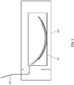
- FIG. 3 illustrates a situation where a sheet jam occurs at the first storage 250.
- the second storage 210, the third storage 220 and the fourth storage 230 are winding storages that wind up a sheet by a cylindrical drum. Consequently, sheets get a tendency to have an arched and curved shape after being stored in the storage. If the sheet having the tendency to have an arched and curved shape is stored in the first storage 250, the sheet is stacked with the shape being arched and curved as it is.
- the drums of the second storage 210, the third storage 220 and the fourth storage 230 wind up the sheet by rotating clockwise in left side view, and release and feed the sheet by rotating counterclockwise.
- the sheets fed from these storages are stacked in the storage box 251, with shapes being warped convex downward. That is, as illustrated in FIG. 3 , there is a possibility that the opposite ends of the sheets at the front and the rear rise. In this case, the sheet being transported by the sixth transporter 240 collides with the ends of the sheets stacked in the storage box 251 to jam therein.
- the sheets are stacked in the storage box 251 of the first storage 250, with the sheets being warped convex upward. That is, the present invention has the configuration where the drums of the second storage 210, the third storage 220 and the fourth storage 230 store the sheet by rotating counterclockwise in left side view, and release and feed the sheet by rotating clockwise.
- the opposite ends of the sheets do not rise in the storage box 251 of the first storage 250, and the apparatus is resistant to sheet jam.
- parts of the third transporter 140 and the fifth transporter 180 are inclined downward, thereby forming stepwise the transport path toward the front (second transport path section).
- the mode of stepwise formation is not limited thereto.
- first diverting section 130, the second diverting section 150 and the third diverting section 170 are disposed sequentially from a higher position to a lower position.
- the second diverting section 150 and the third diverting section 170 are disposed so that the diversion points B1 and C1 are at positions higher than the confluence points B2 and C2, in a manner analogous to that of the first diverting section 130.
- the third transporter 140, the fourth transporter 160 and the fifth transporter 180 are formed horizontally toward the front.
- the second diverting section 150 and the third diverting section 170 serve as a step portion of the transporters that transport the sheet toward the front. In this case, there is no need to incline partially the third transporter 140, the fourth transporter 160 or the fifth transporter 180; this facilitates manufacturing these transporters.
- the present invention is largely applicable to a sheet processing apparatus that stores and ejects sheets.
Landscapes
- Engineering & Computer Science (AREA)
- Mechanical Engineering (AREA)
- Physics & Mathematics (AREA)
- General Physics & Mathematics (AREA)
- Separation, Sorting, Adjustment, Or Bending Of Sheets To Be Conveyed (AREA)
Abstract
Description
- The present invention relates to a sheet processing apparatus that stores and ejects sheets.
- Conventionally, a cash handling apparatus has been known that receives cash, such as banknotes, according to the content of a transaction with a customer, counts and stores the received cash, and dispenses the stored cash according to the count result (e.g., see PTL1).
- PTL1 Japanese Patent Application Laid-Open No.
2012-174047 - Such a cash handling apparatus is required by a user to be reduced in size in consideration of the installation space.
- Unfortunately, reduction in size in turn requires reduction in the sizes of an operation unit, a cash storage and the like. Accordingly, there is a possibility that the operability of the apparatus is degraded and the amount of cash storage is reduced. Furthermore, the cash inlet and outlet have to be reduced in size, and cash inputting and dispensing become inconvenient; thus, there is possibility that the handling property of the apparatus is reduced.
- An object of the present invention is to provide a sheet processing apparatus that securely achieves the operability, handling property, and amount of storage that are analogous to those of the conventional art, while facilitating reduction in the size of the apparatus.
- In order to achieve the above objects, a sheet processing apparatus of the present invention includes: an input section that receives a sheet; a dispensing section that dispenses the sheet; a transporter that transports the sheet input through the input section to the dispensing section; a storage that stores the sheet; and a diverting section that diverts the sheet transported by the transporter to the storage, in which a diversion point at which the sheet is diverted by the diverting section is provided at a position higher than a terminal end of the transporter.
- The sheet processing apparatus of the present invention can securely achieve the operability, handling property, and amount of storage that are analogous to those of the conventional art, while facilitating reduction in the size of the apparatus.
-
-
FIG. 1 is a left side sectional view illustrating a sheet processing apparatus according to an embodiment of the present invention; -
FIG. 2 is an enlarged left side sectional view around a first diverting section, a second diverting section, and a third diverting section; and -
FIG. 3 illustrates a situation where a sheet jam occurs at a first storage. - An embodiment of the present invention is hereinafter described with reference to the accompanying drawings. The accompanying drawings schematically illustrate configuration elements for the sake of easy understanding.
-
FIG. 1 is a left side sectional view illustrating a sheet processing apparatus according to the embodiment of the present invention.FIG. 2 is an enlarged left side sectional view around a first diverting section, a second diverting section, and a third diverting section. - The
sheet processing apparatus 10 according to the embodiment of the present invention includes ahousing 20, aninput section 100 provided on one side of thehousing 20, adispensing section 190 provided on the one side of thehousing 20 and below theinput section 100, and ashutter 200 that covers thedispensing section 190. Thesheet processing apparatus 10 internally includes afirst transporter 120 that transports a sheet to the other side, a turning-back section 125 that changes the transport direction from that toward the other side to that toward the one side, and asecond transporter 135, athird transporter 140, afourth transporter 160, afifth transporter 180 and asixth transporter 240 that transport the sheet to the one side. Thesheet processing apparatus 10 internally includes afirst storage 250, asecond storage 210, athird storage 220 and afourth storage 230 that store sheets. Thesheet processing apparatus 10 includes a firstdiverting section 130, a seconddiverting section 150 and a third divertingsection 170 that divert the sheet. Thesheet processing apparatus 10 includes a control section (not illustrated) that controls the operation of each element. Thefirst transporter 120 constitutes a first transport path section. Thesecond transporter 135, thethird transporter 140, thefourth transporter 160 and thefifth transporter 180 constitute a second transport path section. - Here, the one side or the first side is a side where the
input section 100 and thedispensing section 190 are provided. Hereinafter, the side where theinput section 100 and thedispensing section 190 are provided is called a front surface side. The other side or the second side is a side opposite to the one side. Hereinafter, the side opposite to the one side is called a rear surface side. The left direction of thesheet processing apparatus 10 viewed from the front surface side is called a left side. The direction from the one side (first side) to the other side (second side) is called a first direction. - The
housing 20 has a box shape for storing each element, and includes theinput section 100 and thedispensing section 190 on the front surface side. Thehousing 20 of thesheet processing apparatus 10 according to the embodiment of the present invention is formed to have a desktop size mountable on a table or the like. - The
input section 100 is a receiving section for receiving input sheets. At theinput section 100, an inlet is formed. A user inputs sheets through the inlet into thesheet processing apparatus 10. Theinput section 100 may be configured to receive sheets to be input one-by-one, or to receive multiple sheets collectively. - The
first transporter 120 is a transport path for transporting the sheet input through theinput section 100, to the rear surface side. Thefirst transporter 120 transports the sheet fed by a pair of rollers provided above and below thefirst transporter 120. Thefirst transporter 120 transports the sheet fed by a pair of endless belts (not illustrated) provided above and below thefirst transporter 120. - The endless belts are wound around multiple rollers (not illustrated). At least one roller among the rollers is rotatably driven. The driving force is transmitted to the endless belts, thereby rotating the endless belts.
-
FIG. 1 illustrates the mode where thefirst transporter 120 is formed to be bent multiple times in the vertical direction. Alternatively, thefirst transporter 120 may be linearly formed. - A
recognition unit 110 is a recognition unit that recognizes the sheet input through theinput section 100. Therecognition unit 110 is provided at a position (a position in the first direction viewed from the input section 100) of the middle of the first transporter 120 (first transport path section) on the rear surface side of theinput section 100. As will be apparent from the description below, the second transport path section resides below this position. The second transport path section is oriented toward a lower position as the path approaches the front surface side. Accordingly, the position is accompanied by a relatively large space. Consequently, by disposing therecognition unit 110 having a relatively large size at the position, the entire height of thesheet processing apparatus 10 can be reduced. - The
recognition unit 110 includes sensors, such as an image sensor and a magnetic sensor. Therecognition unit 110 further includes a memory section, such as a memory. - The
recognition unit 110 compares information on the sheet read by the sensor with the information about the sheet stored in the memory section, and determines the type, the authenticity, damage and dirtiness and the like of the sheet. - The control section determines the storage where the sheet is to be stored among the
second storage 210, thethird storage 220 and thefourth storage 230, on the basis of the result of the determination of the type of the sheet by therecognition unit 110. - If the sheet is determined as a counterfeit note or determined to be heavily damaged by the
recognition unit 110, the control section controls each section to store the sheet, as a sheet to be rejected, in thefirst storage 250. The sheet stored in thefirst storage 250 is collected by the user or the like of thesheet processing apparatus 10. - The turning-
back section 125 is a transport path for changing the transport direction of the sheet transported on the rear surface side by thefirst transporter 120 to the front surface side. The turning-backsection 125 is formed to have a circular-arc shape, and its one end is connected to thefirst transporter 120 and the other end is connected to thesecond transporter 135. - Note that the shape of the turning-back
section 125 is not limited to the circular-arc shape. The turning-backsection 125 may include a linearly formed transport path. For example, the turning-backsection 125 may include a circular-arc-shaped transport path for changing, downward, the direction of the transport path oriented toward the rear surface side, a transport path formed linearly downward, and a circular-arc-shaped transport path for changing the direction of the transport path formed downward, to the front surface side. - The
second transporter 135, thethird transporter 140, thefourth transporter 160 and thefifth transporter 180 are transport paths for transporting, to thedispensing section 190, the sheet whose transport direction has been changed from that to the rear to that to the front at the turning-backsection 125; thedispensing section 190 is disposed on the front surface side. - The
second transporter 135 is a transport path that has one end connected to the turning-backsection 125 and is formed obliquely downward and frontward from the turning-backsection 125. The first divertingsection 130 is connected to the other end of thesecond transporter 135. - The
third transporter 140 includes a transport path that has one end connected to the first divertingsection 130 and is formed from the first divertingsection 130 horizontally to the front surface side, and a transport path formed obliquely downward and frontward from the horizontally formed transport path. The second divertingsection 150 is connected to the other end of thethird transporter 140. - The
fourth transporter 160 is a transport path that has one end connected to the second divertingsection 150 and is formed from the second divertingsection 150 toward the front. The third divertingsection 170 is connected to the other end of thefourth transporter 160. - The
fifth transporter 180 includes a transport path that has one end connected to the third divertingsection 170 and is formed from the third divertingsection 170 horizontally frontward, a transport path oriented obliquely downward and frontward from the horizontally formed transport path, and a horizontal transport path formed toward the terminal end from the transport path oriented obliquely downward and frontward. The terminal end of thefifth transporter 180 is disposed above thedispensing section 190. - That is, the transport path (second transport path section) made up of the
second transporter 135, thethird transporter 140, thefourth transporter 160 and thefifth transporter 180, is formed stepwise. Note that the transport path (second transport path section) made up of thesecond transporter 135, thethird transporter 140, thefourth transporter 160 and thefifth transporter 180 is not limited to such a shape. For example, this path may be linearly inclined below, or formed downward with a curved shape. - The first diverting
section 130 is a diverting device that diverts the path to three directions and is for diverting the sheet. - The first diverting
section 130 includes: a cylindrical diverting sectionmain body 130e; aselector 130d that is stored in the diverting sectionmain body 130e and turns centered at the central axis of the diverting sectionmain body 130e as a turning center; threepassage paths main body 130e; and pairs of rollers 130a1, 130b1 and 130c1 provided on the respective passage paths. - The first diverting
section 130 may be configured as an unit including the diverting sectionmain body 130e, theselector 130d, thepassage paths - One
passage path 130a among the three passage paths has an end connected to thesecond transporter 135. The first divertingsection 130 feeds the sheet transported by thesecond transporter 135 to the inside by the pair of rollers 130a1 provided on thepassage path 130a. - Another
passage path 130b among the three passage paths has an end connected to thethird transporter 140. For feeding the sheet toward thethird transporter 140, the first divertingsection 130 feeds the sheet by the pair of rollers 130b1 provided on thepassage path 130b. - Still another
passage path 130c among the three passage paths has an end connected to atransport path 145 connected to thesecond storage 210. For storing the sheet into thesecond storage 210, the pair of rollers 130c1 provided on thepassage path 130c feed the sheet toward thetransport path 145 connected to thesecond storage 210. For feeding the sheet stored in thesecond storage 210 into the first divertingsection 130, the pair of rollers 130c1 provided on thepassage path 130c feed the sheet to the inside. - A space having a substantially triangular prism shape is formed in the diverting section
main body 130e of the first divertingsection 130. Thepassage paths - The
selector 130d is formed to have an A-shape in left side view, and is provided turnably about a horizontal axis extending in the lateral direction. Theselector 130d is controlled to have a predetermined attitude, thereby diverting the sheet fed into the space in the diverting sectionmain body 130e, to a desired passage path. - Hereinafter, a position where a trajectory drawn by the sheet having passed through the
passage path 130a and then been diverted to thethird transporter 140, and a trajectory drawn by the sheet having passed through thepassage path 130a and then been diverted to thesecond storage 210 branch off from each other is called a diversion point A1. A position where a trajectory drawn by the sheet having passed through thepassage path 130a and then been diverted to thethird transporter 140, and a trajectory drawn by the sheet having been stored in thesecond storage 210 and been fed toward thethird transporter 140 become confluent is called a confluence point A2. - The second diverting
section 150 is a diverting device that diverts the path to three directions and is for diverting the sheet. - The second diverting
section 150 includes: a cylindrical diverting sectionmain body 150e; aselector 150d that is stored in the diverting sectionmain body 150e and turns centered at the central axis of the diverting sectionmain body 150e as a turning center; threepassage paths main body 150e; and pairs of rollers 150a1, 150b1 and 150c1 provided on the respective passage paths. - The second diverting
section 150 may be configured as an unit including the diverting sectionmain body 150e, theselector 150d, thepassage paths - One
passage path 150a among the three passage paths has an end connected to thethird transporter 140. The second divertingsection 150 feeds the sheet transported by thethird transporter 140 to the inside by the pair of rollers 150a1 provided on thepassage path 150a. - Another
passage path 150b among the three passage paths has an end connected to thefourth transporter 160. For feeding the sheet toward thefourth transporter 160, the second divertingsection 150 feeds the sheet by the pair of rollers 150b1 provided on thepassage path 150b. - Still another
passage path 150c among the three passage paths has an end connected to thethird storage 220. For storing the sheet into thethird storage 220, the pair of rollers 150c1 provided on thepassage path 150c feed the sheet toward thethird storage 220. For feeding the sheet stored in thethird storage 220 into the second divertingsection 150, the pair of rollers 150c1 provided on thepassage path 150c feed the sheet to the inside. - A space having a substantially triangular prism shape is formed in the diverting section
main body 150e of the second divertingsection 150. Thepassage paths - The
selector 150d is formed to have an A-shape in left side view, and is provided turnably about a horizontal axis extending in the lateral direction. Theselector 150d is controlled to have a predetermined attitude, thereby diverting the sheet fed into the space in the diverting sectionmain body 150e, to a desired passage path. - Hereinafter, a position where a trajectory drawn by the sheet having passed through the
passage path 150a and then been diverted to thefourth transporter 160, and a trajectory drawn by the sheet having passed through thepassage path 150a and then been diverted to thethird storage 220 branch off from each other is called a diversion point B1. A position where a trajectory drawn by the sheet having passed through thepassage path 150a and then been diverted to thefourth transporter 160, and a trajectory drawn by the sheet having been stored in thesecond storage 210 and been fed toward thefourth transporter 160 become confluent is called a confluence point B2. - The third diverting
section 170 is a diverting device that diverts the path to three directions and is for diverting the sheet. - The third diverting
section 170 includes: a cylindrical diverting sectionmain body 170e; aselector 170d that is stored in the diverting sectionmain body 170e and turns centered at the central axis of the diverting sectionmain body 170e as a turning center; threepassage paths main body 170e; and pairs of rollers 170a1, 170b1 and 170c1 provided on the respective passage paths. - The third diverting
section 170 may be configured as an unit including the diverting sectionmain body 170e, theselector 170d, thepassage paths - One
passage path 170a among the three passage paths has an end connected to thefourth transporter 160. The third divertingsection 170 feeds the sheet transported by thefourth transporter 160 to the inside by the pair of rollers 170a1 provided on thepassage path 170a. - Another
passage path 170b among the three passage paths has an end connected to thefifth transporter 180. For feeding the sheet toward thefifth transporter 180, the third divertingsection 170 feeds the sheet by the pair of rollers 170b1 provided on thepassage path 170b. - Still another
passage path 170c among the three passage paths has an end connected to thefourth storage 230. For storing the sheet into thefourth storage 230, the pair of rollers 170c1 provided on thepassage path 170c feed the sheet toward thefourth storage 230. For feeding the sheet stored in thefourth storage 230 into the third divertingsection 170, the pair of rollers 170c1 provided on thepassage path 170c feed the sheet to the inside. - A space having a substantially triangular prism shape is formed in the diverting section
main body 170e of the third divertingsection 170. Thepassage paths - The
selector 170d is formed to have an A-shape in left side view, and is provided turnably about a horizontal axis extending in the lateral direction. Theselector 170d is controlled to have a predetermined attitude, thereby diverting the sheet fed into the space in the diverting sectionmain body 170e, to a desired passage path. - Hereinafter, a position where a trajectory drawn by the sheet having passed through the
passage path 170a and then been diverted to thefifth transporter 180, and a trajectory drawn by the sheet having passed through thepassage path 170a and then been diverted to thefourth storage 230 branch off from each other is called a diversion point C1. A position where a trajectory drawn by the sheet having passed through thepassage path 170a and then been diverted to thefifth transporter 180, and a trajectory drawn by the sheet having been stored in thefourth storage 230 and having been fed toward thefifth transporter 180 become confluent is called a confluence point C2. - In the embodiment of the present invention, the second diverting
section 150 is embedded in thesheet processing apparatus 10 with an attitude where the diversion point B1 and the confluence point B2 of the second divertingsection 150 have the same height. The third divertingsection 170 is embedded in thesheet processing apparatus 10 with an attitude where the diversion point C1 and the confluence point C2 of the third divertingsection 170 have the same height. - Meanwhile, the first diverting
section 130 disposed on the most rear surface side (i.e., a position most apart from the input section 100) is embedded in thesheet processing apparatus 10 so that the diversion point A1 of the first divertingsection 130 can be disposed higher than the confluence point A2. That is, the first divertingsection 130 is embedded in thesheet processing apparatus 10 with an attitude rotated clockwise in left side view with reference to the attitudes of the second divertingsection 150 and the third divertingsection 170. - Accordingly, the position of the diversion point A1 of the first diverting
section 130 can be moved to the front surface side, and the length in the front and rear direction of thesheet processing apparatus 10 can be reduced. - The
second storage 210, thethird storage 220 and thefourth storage 230 are storages that store and dispense the sheet. As illustrated inFIG. 1 , thesecond storage 210, thethird storage 220 and thefourth storage 230 are disposed at positions more apart from theinput section 100 than thefirst storage 250 is. Thesecond storage 210, thethird storage 220 and thefourth storage 230 are winding storages. - Here, the winding storage is a storing unit that causes a drum provided in the unit to wind up and release the sheet together with belt-shaped tapes, thus storing and ejecting the sheet. The drum is a rotation body.
- One ends of a pair of belt-shaped tapes are connected to the outer periphery of the drum. When the drum is rotated counterclockwise in left side view, the belt-shaped tapes are wound up by the drum. At this time, one sheet is clamped by each pair of belt-shaped tapes, and the sheet is wound up by the drum together with the belt-shaped tape.
- When the drum is rotated clockwise, the belt-shaped tapes are released from the drum. At this time, the sheet clamped between the pair of the belt-shaped tapes is fed from the position between the belt-shaped tapes.
- A passage port for the sheet is formed on the upper surface of the
second storage 210. Thetransport path 145 connected to thepassage path 130c communicates with the passage port. Thesecond storage 210 causes the drum to wind up the sheet received through the passage port, thereby storing the sheet in this unit. Thesecond storage 210 releases the sheet wound up by the drum, thereby feeding the sheet through the passage port toward the first divertingsection 130. - A passage port for a sheet is formed on the upper surface of the
third storage 220. Thepassage path 150c of the second divertingsection 150 communicates with the passage port. Thethird storage 220 causes the drum to wind up the sheet received through the passage port, thereby storing the sheet in this unit. Thethird storage 220 releases the sheet wound up by the drum, thereby feeding the sheet through the passage port toward the second divertingsection 150. - A passage port for a sheet is formed on the upper surface of the
fourth storage 230. Thepassage path 170c of the third divertingsection 170 communicates with the passage port. Thefourth storage 230 causes the drum to wind up the sheet received through the passage port, thereby storing the sheet in this unit. Thefourth storage 230 releases the sheet wound up by the drum, thereby feeding the sheet through the passage port toward the third divertingsection 170. - The
sixth transporter 240 is a transport path branched off from thefifth transporter 180. Thesixth transporter 240 transports the sheet toward thefirst storage 250. - A
diverter 270 is provided at a diverter section at which thesixth transporter 240 is branched off from thefifth transporter 180. Thediverter 270 has a function of diverting the sheet transported by thefifth transporter 180 to any of thedispensing section 190 and thefirst storage 250. - The
first storage 250 is a stacking storage that stores the sheet transported by thesixth transporter 240. Thefirst storage 250 stores the sheet through a reception port formed at an upper portion. Thefirst storage 250 internally includes astorage box 251. Thestorage box 251 is detachable to the front from the housing 20 (i.e., in a direction apart from the second storage 210). Thefirst storage 250 may be a winding storage. - The
first storage 250 is formed lower than thesecond storage 210, thethird storage 220 and thefourth storage 230. That is, the upper end of thefirst storage 250 resides at a position lower than the upper ends of thesecond storage 210, thethird storage 220 and thefourth storage 230. - The
dispensing section 190 is a dispensing device that dispenses, to the outside, sheets stored in thesecond storage 210, thethird storage 220 and thefourth storage 230, and a sheet input from theinput section 100 and determined as a sheet to be rejected by therecognition unit 110. Thedispensing section 190 includes a stackingunit 190a that stacks sheets transported by thefifth transporter 180. - A concave is provided frontward of the stacking
unit 190a. The user can take the sheets stacked in the stackingunit 190a, by inserting a hand into the concave disposed below the sheets. - The
shutter 200 is an opening and closing member that opens and closes the outlet of thedispensing section 190. Theshutter 200 is opened and closed by ashutter drive device 200a provided on the rear surface side of theshutter 200. Theshutter 200 covers thedispensing section 190 in a closed state, and opens thedispensing section 190 in an open state. Theshutter drive device 200a may have a configuration where this device is locked in the closed state to thereby prohibit the shutter from being opened, and is unlocked to thereby allow theshutter 200 to be opened. - Next, the operation of each section in a case where the sheet is input into the
sheet processing apparatus 10 is described. First, the operation of each section in a case where the input sheet is stored in thesecond storage 210 is described as an example. - The sheet is input through the
input section 100 provided on the front surface of thesheet processing apparatus 10. The input sheet is transported to therecognition unit 110 by thefirst transporter 120. Therecognition unit 110 determines the type, authenticity, and presence or absence of damage. When the sheet is determined to be a genuine note and without damage by therecognition unit 110, the storage where the sheet is to be stored is determined among thesecond storage 210, thethird storage 220 and thefourth storage 230 according to the type. If the input sheet is determined to be a counterfeit note or have damage by therecognition unit 110 for example, the sheet is determined to be stored in thefirst storage 250. - Irrespective of the recognition result by the
recognition unit 110, the sheet is transported by thefirst transporter 120 to the rear surface side of thesheet processing apparatus 10. The sheet transported by thefirst transporter 120 is changed in transport direction at the turning-backsection 125, and is transported by thesecond transporter 135 to the front surface side. - If the sheet is to be stored in the
second storage 210, the control section controls theselector 130d of the first divertingsection 130 so that thepassage paths section 130 can communicate with each other. - The sheet diverted by the first diverting
section 130 to thesecond storage 210 is fed toward thesecond storage 210 and is stored in thesecond storage 210. At this time, the sheet is wound up together with the pair of belt-shaped tapes by the drum rotating counterclockwise in left side view in thesecond storage 210. - Next, the operation of each section in a case where the input sheet is stored in the
first storage 250 is described as another example. - If the input sheet through the
input section 100 is determined to be a counterfeit note by therecognition unit 110 for example, the sheet is stored in thefirst storage 250. When the sheet is stored in thefirst storage 250, the sheet sequentially passes through thefirst transporter 120, the turning-backsection 125, thesecond transporter 135, the first divertingsection 130, thethird transporter 140, the second divertingsection 150, thefourth transporter 160, the third divertingsection 170, thefifth transporter 180, and thesixth transporter 240, and is stored in thefirst storage 250. - At this time, the
selector 130d of the first divertingsection 130 is controlled so that thepassage paths section 130 can communicate with each other. Theselector 150d of the second divertingsection 150 is controlled so that thepassage paths selector 170d of the third divertingsection 170 is controlled so that thepassage paths diverter 270 is controlled so as to divert the transported sheet to thesixth transporter 240. - As described above, the
storage box 251 of thefirst storage 250 is provided in thehousing 20 detachably to the front. A counterfeit note or the like stored in thefirst storage 250 is taken out from this unit and collected by the user or the like. - Next, the operation of each section in a case where the sheet stored in the
sheet processing apparatus 10 is dispensed is described. Here, the operation of each section in a case where the sheet stored in thesecond storage 210 is dispensed to thedispensing section 190 is described as an example. - When the sheet fed from the
second storage 210 is dispensed to thedispensing section 190, the drum of thesecond storage 210 rotates clockwise in left side view to release the pair of belt-shaped tapes. At this time, the sheet wound up together with the pair of belt-shaped tapes is fed through the passage port of thesecond storage 210 toward the first divertingsection 130. - At this time, the control section controls the
selector 130d of the first divertingsection 130 so that thepassage paths selector 150d so that thepassage paths section 150 can communicate with each other. Theselector 170d is controlled so that thepassage paths section 170 can communicate with each other. - Consequently, the sheet fed from the
second storage 210 sequentially passes through the first divertingsection 130, thethird transporter 140, the second divertingsection 150, thefourth transporter 160, the third divertingsection 170, and thefifth transporter 180, and is dispensed to thedispensing section 190. The sheet dispensed to thedispensing section 190 is stacked in the stackingunit 190a of thedispensing section 190. - After stacking of the dispensed sheets in the stacking
unit 190a is completed, the control section drives and controls theshutter drive device 200a to bring theshutter 200 into the open state. - After the
shutter 200 is opened, the user can take the sheet stacked in the stackingunit 190a. - In the embodiment of the present invention, the transporter that transports the sheet frontward is formed so as to descend toward the front. The
dispensing section 190 is provided at a lower position accordingly. Consequently, the upper area of thedispensing section 190 can be enlarged. - In this case, even if the
dispensing section 190 and theshutter 200 are formed to be large, theshutter 200 can be opened largely above. Consequently, the sheets stacked in the stackingunit 190a can become easily viewable by the user, and the sheets can be smoothly taken from thedispensing section 190 even if the fingers and thumb of the user are relatively thick. Furthermore, thedispensing section 190 can be formed large, which can increase the amount of stackable sheets. - Next, a configuration for preventing the sheet from jamming the
first storage 250 is described.FIG. 3 illustrates a situation where a sheet jam occurs at thefirst storage 250. - The
second storage 210, thethird storage 220 and thefourth storage 230 are winding storages that wind up a sheet by a cylindrical drum. Consequently, sheets get a tendency to have an arched and curved shape after being stored in the storage. If the sheet having the tendency to have an arched and curved shape is stored in thefirst storage 250, the sheet is stacked with the shape being arched and curved as it is. - It is herein assumed that the drums of the
second storage 210, thethird storage 220 and thefourth storage 230 wind up the sheet by rotating clockwise in left side view, and release and feed the sheet by rotating counterclockwise. In this case, the sheets fed from these storages are stacked in thestorage box 251, with shapes being warped convex downward. That is, as illustrated inFIG. 3 , there is a possibility that the opposite ends of the sheets at the front and the rear rise. In this case, the sheet being transported by thesixth transporter 240 collides with the ends of the sheets stacked in thestorage box 251 to jam therein. - Accordingly, in the embodiment of the present invention, the sheets are stacked in the
storage box 251 of thefirst storage 250, with the sheets being warped convex upward. That is, the present invention has the configuration where the drums of thesecond storage 210, thethird storage 220 and thefourth storage 230 store the sheet by rotating counterclockwise in left side view, and release and feed the sheet by rotating clockwise. - Consequently, according to the
sheet processing apparatus 10 of the present invention, the opposite ends of the sheets do not rise in thestorage box 251 of thefirst storage 250, and the apparatus is resistant to sheet jam. - In the embodiment of the present invention, parts of the
third transporter 140 and thefifth transporter 180 are inclined downward, thereby forming stepwise the transport path toward the front (second transport path section). However, the mode of stepwise formation is not limited thereto. - For example, the first diverting
section 130, the second divertingsection 150 and the third divertingsection 170 are disposed sequentially from a higher position to a lower position. The second divertingsection 150 and the third divertingsection 170 are disposed so that the diversion points B1 and C1 are at positions higher than the confluence points B2 and C2, in a manner analogous to that of the first divertingsection 130. Thethird transporter 140, thefourth transporter 160 and thefifth transporter 180 are formed horizontally toward the front. - Accordingly, the second diverting
section 150 and the third divertingsection 170 serve as a step portion of the transporters that transport the sheet toward the front. In this case, there is no need to incline partially thethird transporter 140, thefourth transporter 160 or thefifth transporter 180; this facilitates manufacturing these transporters. - The present invention is largely applicable to a sheet processing apparatus that stores and ejects sheets.
-
- 10 Sheet processing apparatus
- 20 Housing
- 100 Input section
- 110 Recognition unit
- 120 First transporter
- 125 Turning-back section
- 130 First diverting section
- 130a, 130b, 130c Passage path
- 130a1, 130b1, 130c1 Rollers
- 130d Selector
- 130e Diverting section main body
- 135 Second transporter
- 140 Third transporter
- 150 Second diverting section
- 150a, 150b, 150c Passage path
- 150a1, 150b1, 150c1 Rollers
- 150d Selector
- 150e Diverting section main body
- 160 Fourth transporter
- 170 Third diverting section
- 170a, 170b, 170c Passage path
- 170a1, 170b1, 170c1 Rollers
- 170d Selector
- 170e Diverting section main body
- 180 Fifth transporter
- 190 Dispensing section
- 190a Stacking unit
- 200 Shutter
- 200a Shutter drive device
- 210 Second storage
- 220 Third storage
- 230 Fourth storage
- 240 Sixth transporter
- 250 First storage
- A1, B1, C1 Diversion point
- A2, B2, C2 Confluence point
Claims (14)
- A sheet processing apparatus(10), comprising:an input section (100) that receives a sheet;a dispensing section (190) that dispenses the sheet;a transporter (120, 125, 135, 140, 160, 180, 240) that transports the sheet input through the input section to the dispensing section, the transporter having a terminal end;a storage (210, 220, 230, 250) that stores the sheet; andat least one diverting section (130, 150, 170) that diverts the sheet transported by the transporter to the storage,wherein a diversion point (A1, B1, C1) at which the sheet is diverted by the at least one diverting section is provided at a position higher than the terminal end of the transporter.
- The sheet processing apparatus according to claim 1,
wherein the transporter includes:a first transport path section (120) that transports the sheet from a first side of the sheet processing apparatus where the input section is arranged to a second side of the sheet processing apparatus, the second side being opposite to the first side,a second transport path section (135, 140, 160, 180) that transports the sheet toward the dispensing section from the second side to the first side, anda turning-back section (125) that connects the first transport path section and the second transport path section to each other, andwherein at least a part of the second transport path section is formed inclined downward toward the terminal end. - The sheet processing apparatus according to claim 1,
wherein the transporter includes:a first transport path section (120) that transports the sheet from a first side of the sheet processing apparatus where the input section is arranged to a second side of the sheet processing apparatus, the second side being opposite to the first side,a second transport path section (135, 140, 160, 180) that transports the sheet toward the dispensing section from the second side to the first side, anda turning-back section (125) that connects the first transport path section and the second transport path section to each other, andwherein at least a part of the second transport path section is formed stepwise downward toward the terminal end. - The sheet processing apparatus according to any one of claims 1 to 3, wherein the diverting section diverts the sheet to either of two directions.
- The sheet processing apparatus according to any one of claims 1 to 4,
wherein the storage includes a first storage (250), and a second storage (210, 220, 230), wherein the second storage is disposed at a position further apart from the input section than the first storage is, and
wherein an upper end of the first storage is formed at a position lower than an upper end of the second storage. - The sheet processing apparatus according to claim 5, wherein the second storage stores and feeds the sheet.
- The sheet processing apparatus according to claim 5 or 6, wherein the second storage is a winding storage comprising a rotation body, wherein the winding storage stores the sheet by winding up the sheet around the rotation body.
- The sheet processing apparatus according to claim 7, wherein the second storage rotates the rotation body counterclockwise in left side view when storing the sheet.
- The sheet processing apparatus according to any one of claims 5 to 8, wherein the first storage is provided such that the sheet to be collected is stacked in the first storage and the first storage is capable of being taken out in a direction apart from the second storage.
- The sheet processing apparatus according to any one of claims 5 to 9, further comprising a recognition determiner (110) arranged in a first direction relative to the input section, wherein the recognition determiner is operable to recognize the sheet input through the input section, wherein a direction viewed from the first storage to where the second storage is disposed is the first direction.
- The sheet processing apparatus according to claim 10,
wherein the at least one diverting section comprises a plurality of the diverting sections, and the diversion point and a confluence point (A2, B2, C2) are disposed in each of the plurality of the diverting sections, the confluence point residing at a position where a trajectory drawn by the sheet when the sheet input through the input section is transported to the dispensing section and a trajectory drawn by the sheet when the sheet stored in the second storage is fed toward the dispensing section become confluent, and
wherein the diversion point disposed in a diverting section disposed at a position most apart from the input section among the plurality of diverting sections is disposed at a position higher than the confluence point disposed in the diverting section disposed at the position most apart from the input section. - The sheet processing apparatus according to any one of claims 1 to 11, further comprising a shutter (200), wherein the dispensing section is provided with the shutter covering the dispensing section.
- The sheet processing apparatus according to claim 12, further comprising a drive mechanism (200a) driving the shutter arranged above the dispensing section.
- The sheet processing apparatus according to any one of claims 1 to 13, wherein the diversion point is provided at a position lower than the input section.
Applications Claiming Priority (1)
| Application Number | Priority Date | Filing Date | Title |
|---|---|---|---|
| JP2017209237A JP2019082804A (en) | 2017-10-30 | 2017-10-30 | Paper sheet processor |
Publications (2)
| Publication Number | Publication Date |
|---|---|
| EP3477604A1 true EP3477604A1 (en) | 2019-05-01 |
| EP3477604B1 EP3477604B1 (en) | 2024-12-11 |
Family
ID=64048706
Family Applications (1)
| Application Number | Title | Priority Date | Filing Date |
|---|---|---|---|
| EP18203251.6A Active EP3477604B1 (en) | 2017-10-30 | 2018-10-30 | Sheet processing apparatus |
Country Status (3)
| Country | Link |
|---|---|
| US (1) | US10899571B2 (en) |
| EP (1) | EP3477604B1 (en) |
| JP (1) | JP2019082804A (en) |
Citations (3)
| Publication number | Priority date | Publication date | Assignee | Title |
|---|---|---|---|---|
| JP2012174047A (en) | 2011-02-22 | 2012-09-10 | Glory Ltd | Paper money processor |
| US20160163160A1 (en) * | 2013-09-13 | 2016-06-09 | Oki Electric Industry Co., Ltd. | Banknote pay-in/pay-out device and banknote transaction device |
| US20170309133A1 (en) * | 2014-09-11 | 2017-10-26 | Oki Electric Industry Co., Ltd. | Medium processing device and medium transaction device |
Family Cites Families (5)
| Publication number | Priority date | Publication date | Assignee | Title |
|---|---|---|---|---|
| JP4768329B2 (en) * | 2005-06-17 | 2011-09-07 | 株式会社東芝 | Paper sheet processing equipment |
| JP2008046870A (en) * | 2006-08-16 | 2008-02-28 | Glory Ltd | Banknote handling equipment |
| JP5341169B2 (en) * | 2009-02-19 | 2013-11-13 | グローリー株式会社 | Paper sheet counting device |
| WO2012115055A1 (en) * | 2011-02-22 | 2012-08-30 | グローリー株式会社 | Paper currency processing device |
| JP5749688B2 (en) * | 2012-06-18 | 2015-07-15 | 日立オムロンターミナルソリューションズ株式会社 | Banknote handling equipment |
-
2017
- 2017-10-30 JP JP2017209237A patent/JP2019082804A/en active Pending
-
2018
- 2018-10-30 US US16/174,322 patent/US10899571B2/en active Active
- 2018-10-30 EP EP18203251.6A patent/EP3477604B1/en active Active
Patent Citations (3)
| Publication number | Priority date | Publication date | Assignee | Title |
|---|---|---|---|---|
| JP2012174047A (en) | 2011-02-22 | 2012-09-10 | Glory Ltd | Paper money processor |
| US20160163160A1 (en) * | 2013-09-13 | 2016-06-09 | Oki Electric Industry Co., Ltd. | Banknote pay-in/pay-out device and banknote transaction device |
| US20170309133A1 (en) * | 2014-09-11 | 2017-10-26 | Oki Electric Industry Co., Ltd. | Medium processing device and medium transaction device |
Also Published As
| Publication number | Publication date |
|---|---|
| JP2019082804A (en) | 2019-05-30 |
| US10899571B2 (en) | 2021-01-26 |
| EP3477604B1 (en) | 2024-12-11 |
| US20190127173A1 (en) | 2019-05-02 |
Similar Documents
| Publication | Publication Date | Title |
|---|---|---|
| JP5474492B2 (en) | Banknote deposit device | |
| US6889897B2 (en) | Bill receiving/paying device and automated cash transaction apparatus | |
| EP2471731A1 (en) | Reversible banknote conveying channel device | |
| JP5375425B2 (en) | Coin processing equipment | |
| WO2012164629A1 (en) | Bill storage box and bill handling device | |
| JP5950839B2 (en) | Transport control device | |
| US20150344255A1 (en) | Diverter, medium handling apparatus and financial device | |
| CN101884055B (en) | Apparatus for accepting and dispensing bank notes | |
| CN106251470A (en) | Cash automated trading device | |
| JP5153530B2 (en) | Banknote deposit and withdrawal machine | |
| JP2008021113A (en) | Paper sheet stacking device | |
| JP6547344B2 (en) | Medium storage and medium handling device | |
| EP3477604B1 (en) | Sheet processing apparatus | |
| JP5893473B2 (en) | Money handling equipment | |
| EP3115974B1 (en) | Paper sheet processing device | |
| JP6259725B2 (en) | Paper sheet separating and accumulating equipment | |
| JP5791464B2 (en) | Banknote holding and separating mechanism and reflux-type banknote processing apparatus using the same | |
| US9003748B2 (en) | Coin processing unit | |
| JP5165196B2 (en) | Banknote deposit and withdrawal machine | |
| JP7808518B2 (en) | Storage mechanism and coin processing machine | |
| JP7808519B2 (en) | currency handling machine | |
| JP7791786B2 (en) | coin handling machine | |
| JP5498549B2 (en) | Banknote deposit and withdrawal machine | |
| CN101939767A (en) | Device for receiving and dispensing banknotes | |
| JP4110183B2 (en) | Bill storage bin |
Legal Events
| Date | Code | Title | Description |
|---|---|---|---|
| PUAI | Public reference made under article 153(3) epc to a published international application that has entered the european phase |
Free format text: ORIGINAL CODE: 0009012 |
|
| STAA | Information on the status of an ep patent application or granted ep patent |
Free format text: STATUS: THE APPLICATION HAS BEEN PUBLISHED |
|
| AK | Designated contracting states |
Kind code of ref document: A1 Designated state(s): AL AT BE BG CH CY CZ DE DK EE ES FI FR GB GR HR HU IE IS IT LI LT LU LV MC MK MT NL NO PL PT RO RS SE SI SK SM TR |
|
| AX | Request for extension of the european patent |
Extension state: BA ME |
|
| STAA | Information on the status of an ep patent application or granted ep patent |
Free format text: STATUS: REQUEST FOR EXAMINATION WAS MADE |
|
| 17P | Request for examination filed |
Effective date: 20191031 |
|
| STAA | Information on the status of an ep patent application or granted ep patent |
Free format text: STATUS: EXAMINATION IS IN PROGRESS |
|
| 17Q | First examination report despatched |
Effective date: 20220901 |
|
| P01 | Opt-out of the competence of the unified patent court (upc) registered |
Effective date: 20230531 |
|
| REG | Reference to a national code |
Ref country code: DE Ref legal event code: R079 Free format text: PREVIOUS MAIN CLASS: G07D0011180000 Ipc: B65H0029000000 Ref country code: DE Ref legal event code: R079 Ref document number: 602018077461 Country of ref document: DE Free format text: PREVIOUS MAIN CLASS: G07D0011180000 Ipc: B65H0029000000 |
|
| RIC1 | Information provided on ipc code assigned before grant |
Ipc: B65H 29/58 20060101ALI20240617BHEP Ipc: G07D 11/40 20190101ALI20240617BHEP Ipc: G07D 11/18 20190101ALI20240617BHEP Ipc: B65H 39/115 20060101ALI20240617BHEP Ipc: B65H 31/02 20060101ALI20240617BHEP Ipc: B65H 29/12 20060101ALI20240617BHEP Ipc: B65H 29/00 20060101AFI20240617BHEP |
|
| GRAP | Despatch of communication of intention to grant a patent |
Free format text: ORIGINAL CODE: EPIDOSNIGR1 |
|
| STAA | Information on the status of an ep patent application or granted ep patent |
Free format text: STATUS: GRANT OF PATENT IS INTENDED |
|
| INTG | Intention to grant announced |
Effective date: 20240806 |
|
| GRAS | Grant fee paid |
Free format text: ORIGINAL CODE: EPIDOSNIGR3 |
|
| GRAA | (expected) grant |
Free format text: ORIGINAL CODE: 0009210 |
|
| STAA | Information on the status of an ep patent application or granted ep patent |
Free format text: STATUS: THE PATENT HAS BEEN GRANTED |
|
| AK | Designated contracting states |
Kind code of ref document: B1 Designated state(s): AL AT BE BG CH CY CZ DE DK EE ES FI FR GB GR HR HU IE IS IT LI LT LU LV MC MK MT NL NO PL PT RO RS SE SI SK SM TR |
|
| REG | Reference to a national code |
Ref country code: GB Ref legal event code: FG4D |
|
| REG | Reference to a national code |
Ref country code: CH Ref legal event code: EP |
|
| REG | Reference to a national code |
Ref country code: IE Ref legal event code: FG4D |
|
| REG | Reference to a national code |
Ref country code: DE Ref legal event code: R096 Ref document number: 602018077461 Country of ref document: DE |
|
| REG | Reference to a national code |
Ref country code: LT Ref legal event code: MG9D |
|
| PG25 | Lapsed in a contracting state [announced via postgrant information from national office to epo] |
Ref country code: HR Free format text: LAPSE BECAUSE OF FAILURE TO SUBMIT A TRANSLATION OF THE DESCRIPTION OR TO PAY THE FEE WITHIN THE PRESCRIBED TIME-LIMIT Effective date: 20241211 |
|
| PG25 | Lapsed in a contracting state [announced via postgrant information from national office to epo] |
Ref country code: FI Free format text: LAPSE BECAUSE OF FAILURE TO SUBMIT A TRANSLATION OF THE DESCRIPTION OR TO PAY THE FEE WITHIN THE PRESCRIBED TIME-LIMIT Effective date: 20241211 |
|
| PG25 | Lapsed in a contracting state [announced via postgrant information from national office to epo] |
Ref country code: BG Free format text: LAPSE BECAUSE OF FAILURE TO SUBMIT A TRANSLATION OF THE DESCRIPTION OR TO PAY THE FEE WITHIN THE PRESCRIBED TIME-LIMIT Effective date: 20241211 |
|
| REG | Reference to a national code |
Ref country code: NL Ref legal event code: MP Effective date: 20241211 |
|
| PG25 | Lapsed in a contracting state [announced via postgrant information from national office to epo] |
Ref country code: ES Free format text: LAPSE BECAUSE OF FAILURE TO SUBMIT A TRANSLATION OF THE DESCRIPTION OR TO PAY THE FEE WITHIN THE PRESCRIBED TIME-LIMIT Effective date: 20241211 |
|
| PG25 | Lapsed in a contracting state [announced via postgrant information from national office to epo] |
Ref country code: NO Free format text: LAPSE BECAUSE OF FAILURE TO SUBMIT A TRANSLATION OF THE DESCRIPTION OR TO PAY THE FEE WITHIN THE PRESCRIBED TIME-LIMIT Effective date: 20250311 |
|
| PG25 | Lapsed in a contracting state [announced via postgrant information from national office to epo] |
Ref country code: LV Free format text: LAPSE BECAUSE OF FAILURE TO SUBMIT A TRANSLATION OF THE DESCRIPTION OR TO PAY THE FEE WITHIN THE PRESCRIBED TIME-LIMIT Effective date: 20241211 Ref country code: GR Free format text: LAPSE BECAUSE OF FAILURE TO SUBMIT A TRANSLATION OF THE DESCRIPTION OR TO PAY THE FEE WITHIN THE PRESCRIBED TIME-LIMIT Effective date: 20250312 |
|
| PG25 | Lapsed in a contracting state [announced via postgrant information from national office to epo] |
Ref country code: RS Free format text: LAPSE BECAUSE OF FAILURE TO SUBMIT A TRANSLATION OF THE DESCRIPTION OR TO PAY THE FEE WITHIN THE PRESCRIBED TIME-LIMIT Effective date: 20250311 |
|
| PG25 | Lapsed in a contracting state [announced via postgrant information from national office to epo] |
Ref country code: NL Free format text: LAPSE BECAUSE OF FAILURE TO SUBMIT A TRANSLATION OF THE DESCRIPTION OR TO PAY THE FEE WITHIN THE PRESCRIBED TIME-LIMIT Effective date: 20241211 |
|
| REG | Reference to a national code |
Ref country code: AT Ref legal event code: MK05 Ref document number: 1750263 Country of ref document: AT Kind code of ref document: T Effective date: 20241211 |
|
| PG25 | Lapsed in a contracting state [announced via postgrant information from national office to epo] |
Ref country code: SM Free format text: LAPSE BECAUSE OF FAILURE TO SUBMIT A TRANSLATION OF THE DESCRIPTION OR TO PAY THE FEE WITHIN THE PRESCRIBED TIME-LIMIT Effective date: 20241211 |
|
| PG25 | Lapsed in a contracting state [announced via postgrant information from national office to epo] |
Ref country code: PL Free format text: LAPSE BECAUSE OF FAILURE TO SUBMIT A TRANSLATION OF THE DESCRIPTION OR TO PAY THE FEE WITHIN THE PRESCRIBED TIME-LIMIT Effective date: 20241211 |
|
| PG25 | Lapsed in a contracting state [announced via postgrant information from national office to epo] |
Ref country code: IS Free format text: LAPSE BECAUSE OF FAILURE TO SUBMIT A TRANSLATION OF THE DESCRIPTION OR TO PAY THE FEE WITHIN THE PRESCRIBED TIME-LIMIT Effective date: 20250411 |
|
| PG25 | Lapsed in a contracting state [announced via postgrant information from national office to epo] |
Ref country code: PT Free format text: LAPSE BECAUSE OF FAILURE TO SUBMIT A TRANSLATION OF THE DESCRIPTION OR TO PAY THE FEE WITHIN THE PRESCRIBED TIME-LIMIT Effective date: 20250411 |
|
| PG25 | Lapsed in a contracting state [announced via postgrant information from national office to epo] |
Ref country code: EE Free format text: LAPSE BECAUSE OF FAILURE TO SUBMIT A TRANSLATION OF THE DESCRIPTION OR TO PAY THE FEE WITHIN THE PRESCRIBED TIME-LIMIT Effective date: 20241211 |
|
| PG25 | Lapsed in a contracting state [announced via postgrant information from national office to epo] |
Ref country code: RO Free format text: LAPSE BECAUSE OF FAILURE TO SUBMIT A TRANSLATION OF THE DESCRIPTION OR TO PAY THE FEE WITHIN THE PRESCRIBED TIME-LIMIT Effective date: 20241211 Ref country code: AT Free format text: LAPSE BECAUSE OF FAILURE TO SUBMIT A TRANSLATION OF THE DESCRIPTION OR TO PAY THE FEE WITHIN THE PRESCRIBED TIME-LIMIT Effective date: 20241211 |
|
| PG25 | Lapsed in a contracting state [announced via postgrant information from national office to epo] |
Ref country code: SK Free format text: LAPSE BECAUSE OF FAILURE TO SUBMIT A TRANSLATION OF THE DESCRIPTION OR TO PAY THE FEE WITHIN THE PRESCRIBED TIME-LIMIT Effective date: 20241211 |
|
| PG25 | Lapsed in a contracting state [announced via postgrant information from national office to epo] |
Ref country code: CZ Free format text: LAPSE BECAUSE OF FAILURE TO SUBMIT A TRANSLATION OF THE DESCRIPTION OR TO PAY THE FEE WITHIN THE PRESCRIBED TIME-LIMIT Effective date: 20241211 |
|
| PG25 | Lapsed in a contracting state [announced via postgrant information from national office to epo] |
Ref country code: IT Free format text: LAPSE BECAUSE OF FAILURE TO SUBMIT A TRANSLATION OF THE DESCRIPTION OR TO PAY THE FEE WITHIN THE PRESCRIBED TIME-LIMIT Effective date: 20241211 |
|
| PG25 | Lapsed in a contracting state [announced via postgrant information from national office to epo] |
Ref country code: SE Free format text: LAPSE BECAUSE OF FAILURE TO SUBMIT A TRANSLATION OF THE DESCRIPTION OR TO PAY THE FEE WITHIN THE PRESCRIBED TIME-LIMIT Effective date: 20241211 |
|
| REG | Reference to a national code |
Ref country code: DE Ref legal event code: R097 Ref document number: 602018077461 Country of ref document: DE |
|
| PG25 | Lapsed in a contracting state [announced via postgrant information from national office to epo] |
Ref country code: DK Free format text: LAPSE BECAUSE OF FAILURE TO SUBMIT A TRANSLATION OF THE DESCRIPTION OR TO PAY THE FEE WITHIN THE PRESCRIBED TIME-LIMIT Effective date: 20241211 |
|
| PLBE | No opposition filed within time limit |
Free format text: ORIGINAL CODE: 0009261 |
|
| STAA | Information on the status of an ep patent application or granted ep patent |
Free format text: STATUS: NO OPPOSITION FILED WITHIN TIME LIMIT |
|
| 26N | No opposition filed |
Effective date: 20250912 |
|
| PGFP | Annual fee paid to national office [announced via postgrant information from national office to epo] |
Ref country code: DE Payment date: 20251021 Year of fee payment: 8 |
|
| PGFP | Annual fee paid to national office [announced via postgrant information from national office to epo] |
Ref country code: GB Payment date: 20251022 Year of fee payment: 8 |
|
| PGFP | Annual fee paid to national office [announced via postgrant information from national office to epo] |
Ref country code: FR Payment date: 20251030 Year of fee payment: 8 |