EP3477548A1 - Method and image capturing device for detecting fog in a scene - Google Patents
Method and image capturing device for detecting fog in a scene Download PDFInfo
- Publication number
- EP3477548A1 EP3477548A1 EP17197933.9A EP17197933A EP3477548A1 EP 3477548 A1 EP3477548 A1 EP 3477548A1 EP 17197933 A EP17197933 A EP 17197933A EP 3477548 A1 EP3477548 A1 EP 3477548A1
- Authority
- EP
- European Patent Office
- Prior art keywords
- image
- scene
- contrast
- capturing device
- image capturing
- Prior art date
- Legal status (The legal status is an assumption and is not a legal conclusion. Google has not performed a legal analysis and makes no representation as to the accuracy of the status listed.)
- Granted
Links
Images

Classifications
-
- G—PHYSICS
- G06—COMPUTING OR CALCULATING; COUNTING
- G06T—IMAGE DATA PROCESSING OR GENERATION, IN GENERAL
- G06T7/00—Image analysis
- G06T7/10—Segmentation; Edge detection
- G06T7/11—Region-based segmentation
-
- G—PHYSICS
- G06—COMPUTING OR CALCULATING; COUNTING
- G06T—IMAGE DATA PROCESSING OR GENERATION, IN GENERAL
- G06T5/00—Image enhancement or restoration
- G06T5/73—Deblurring; Sharpening
-
- G—PHYSICS
- G06—COMPUTING OR CALCULATING; COUNTING
- G06V—IMAGE OR VIDEO RECOGNITION OR UNDERSTANDING
- G06V20/00—Scenes; Scene-specific elements
- G06V20/50—Context or environment of the image
- G06V20/56—Context or environment of the image exterior to a vehicle by using sensors mounted on the vehicle
-
- G—PHYSICS
- G06—COMPUTING OR CALCULATING; COUNTING
- G06T—IMAGE DATA PROCESSING OR GENERATION, IN GENERAL
- G06T5/00—Image enhancement or restoration
- G06T5/40—Image enhancement or restoration using histogram techniques
-
- G—PHYSICS
- G06—COMPUTING OR CALCULATING; COUNTING
- G06T—IMAGE DATA PROCESSING OR GENERATION, IN GENERAL
- G06T7/00—Image analysis
- G06T7/0002—Inspection of images, e.g. flaw detection
-
- G—PHYSICS
- G06—COMPUTING OR CALCULATING; COUNTING
- G06T—IMAGE DATA PROCESSING OR GENERATION, IN GENERAL
- G06T7/00—Image analysis
- G06T7/90—Determination of colour characteristics
-
- G—PHYSICS
- G06—COMPUTING OR CALCULATING; COUNTING
- G06V—IMAGE OR VIDEO RECOGNITION OR UNDERSTANDING
- G06V10/00—Arrangements for image or video recognition or understanding
- G06V10/10—Image acquisition
- G06V10/12—Details of acquisition arrangements; Constructional details thereof
- G06V10/14—Optical characteristics of the device performing the acquisition or on the illumination arrangements
- G06V10/143—Sensing or illuminating at different wavelengths
-
- G—PHYSICS
- G06—COMPUTING OR CALCULATING; COUNTING
- G06V—IMAGE OR VIDEO RECOGNITION OR UNDERSTANDING
- G06V20/00—Scenes; Scene-specific elements
- G06V20/50—Context or environment of the image
- G06V20/52—Surveillance or monitoring of activities, e.g. for recognising suspicious objects
-
- H—ELECTRICITY
- H04—ELECTRIC COMMUNICATION TECHNIQUE
- H04N—PICTORIAL COMMUNICATION, e.g. TELEVISION
- H04N23/00—Cameras or camera modules comprising electronic image sensors; Control thereof
- H04N23/56—Cameras or camera modules comprising electronic image sensors; Control thereof provided with illuminating means
-
- H—ELECTRICITY
- H04—ELECTRIC COMMUNICATION TECHNIQUE
- H04N—PICTORIAL COMMUNICATION, e.g. TELEVISION
- H04N23/00—Cameras or camera modules comprising electronic image sensors; Control thereof
- H04N23/70—Circuitry for compensating brightness variation in the scene
- H04N23/71—Circuitry for evaluating the brightness variation
-
- G—PHYSICS
- G06—COMPUTING OR CALCULATING; COUNTING
- G06T—IMAGE DATA PROCESSING OR GENERATION, IN GENERAL
- G06T2207/00—Indexing scheme for image analysis or image enhancement
- G06T2207/10—Image acquisition modality
- G06T2207/10048—Infrared image
-
- G—PHYSICS
- G06—COMPUTING OR CALCULATING; COUNTING
- G06T—IMAGE DATA PROCESSING OR GENERATION, IN GENERAL
- G06T2207/00—Indexing scheme for image analysis or image enhancement
- G06T2207/10—Image acquisition modality
- G06T2207/10141—Special mode during image acquisition
- G06T2207/10152—Varying illumination
-
- G—PHYSICS
- G06—COMPUTING OR CALCULATING; COUNTING
- G06T—IMAGE DATA PROCESSING OR GENERATION, IN GENERAL
- G06T2207/00—Indexing scheme for image analysis or image enhancement
- G06T2207/30—Subject of image; Context of image processing
- G06T2207/30168—Image quality inspection
-
- G—PHYSICS
- G06—COMPUTING OR CALCULATING; COUNTING
- G06T—IMAGE DATA PROCESSING OR GENERATION, IN GENERAL
- G06T2207/00—Indexing scheme for image analysis or image enhancement
- G06T2207/30—Subject of image; Context of image processing
- G06T2207/30181—Earth observation
- G06T2207/30192—Weather; Meteorology
-
- G—PHYSICS
- G06—COMPUTING OR CALCULATING; COUNTING
- G06T—IMAGE DATA PROCESSING OR GENERATION, IN GENERAL
- G06T2210/00—Indexing scheme for image generation or computer graphics
- G06T2210/24—Fluid dynamics
Definitions
- Embodiments herein relate to image processing, such as automatic detection, automatic classification, image enhancement and the like.
- image processing such as automatic detection, automatic classification, image enhancement and the like.
- a method and an image capturing device for detecting fog in a scene are disclosed.
- a corresponding computer program and a computer program carrier are also disclosed.
- Image processing refers to any processing that is applied to an image.
- the processing can include application of various effects, masks, filters or the like, to the image.
- the image can be enhanced in terms of contrast, converted to grey scale, or altered in some way.
- the image has typically been captured by a video camera, a still image camera or the like.
- contrast enhancing processing With reference to the contrast enhancing processing, some challenges arise when it is not known whether the scene to be captured includes fog or not. Should it be assumed that fog is present and contrast enhancing processing is applied all the time, this may cause severe quality degradation to images depicting scenes which do not include fog.
- the contrast enhancing processing is thus of limited use when it is not known whether the weather has caused fog in the image or not. Therefore, an operator of for example a video surveillance system manually turn on contrast enhancing processing when he/she observes fog in the images captured by the video surveillance system. Disadvantageously, there is thus a risk that the operator, or another operator on duty, forgets to turn off the contrast enhancing processing when not needed anymore, e.g. when the fog is gone, or almost gone.
- a problem may therefore be related to how to automatically detect whether a scene imaged by a device includes fog or not.
- a histogram of an image of the scene may be used in order to get a hint of whether or not fog is present in the scene.
- the histogram is a plot illustrating number of pixels versus a range of available pixel values of the image.
- the histogram is said to be flat, i.e. relatively many of the available pixel values are represented by a similar amount of pixels, it can be assumed that there is fog in the scene.
- scenes with flat dynamics without fog will also be represented by a similar histogram, which thus will cause the known measures to erroneously assume the scene to include fog. Any subsequently applied contrast enhancing processing would thus degrade quality of the image.
- An object may be to how to solve, or at least partly solve, the above mentioned problem while reducing shortcomings of the known measures.
- the object is achieved by a method, performed by an image capturing device, for detecting fog in a scene imaged using the image capturing device are disclosed.
- the image capturing device captures a first image of the scene without illuminating the scene with IR radiation.
- the image capturing device determines a first value of a measure relating to contrast for the first image.
- the image capturing device captures a second image of the scene while illuminating the scene with IR radiation.
- the image capturing device determines a second value of the measure relating to contrast for the second image.
- a difference between the first contrast and a second contrast, indicated by the second value is greater than a second threshold value, the image capturing device determines that there is fog in the scene.
- the object is achieved by an image capturing device configured for performing the method above.
- the object is achieved by a computer program and a computer program carrier corresponding to the aspects above.
- the image capturing device determines the second value of the measure relating to contrast for the second image, which is captured while illuminating the scene with IR radiation. In this manner, the image capturing device may obtain the second contrast of the second image, whereby additional information of the scene when illuminated by IR radiation has been gathered. The image capturing device may then compare the difference between the first and second contrasts to the second threshold value in order to determine whether or not there is fog in the scene. Hence, thanks to the comparison of the difference to the second threshold, the image capturing device may be able to determine that there is fog in the scene when the difference is greater than the second threshold value and that there is no fog, or at least no detectable amounts of fogs, in the scene when the difference is less than the second threshold value.
- the measure relating to contrast of an image may be represented by a histogram, a ratio between maximum pixel count and minimum pixel count of the histogram, a sharpness of edges, a ratio of local maximum and minimum values, a so called Sobel filter for edge detection, any other suitable filter for edge detection or the like.
- the measure may further be represented by any quantity, determined based on an image, for the purpose of autofocus and/or contrast evaluation.
- an advantage is thus that the embodiments herein enable improvement of image quality, such as contrast, or the like, even under varying whether conditions, e.g. no fog, with fog, since the embodiments herein provide automatic detection of fog.
- the improvement of the image quality is enabled thanks to that selection of whether or not to apply contrast enhancing processing or capturing of images with IR illumination may be based on whether or not fog is present as determined by the embodiment herein.
- Figure 1 depicts an exemplifying image capturing device 110, such as a video recorder, a surveillance camera 120, a digital camera, a smartphone 130 including an image sensor, a car 140 including an image sensor, a wired or wireless device capable of obtaining images over a network or the like.
- the image capturing device 110 may be comprised in the surveillance camera 120, the smartphone 130, the car 140 or the like.
- the image capturing device 110 is capable of processing an image.
- the image may have been captured by the image capturing device 110 itself or it may have been received from another device, which captured the image, or from a memory, such as hard drive or the like.
- the image capturing device 110 is described in more detail with reference to Figure 5 below. However, in order to provide some definitions and context for the description relating to Figure 3 below, it may be noted that the image capturing device 110 may comprise an image sensor for capturing images.
- the image sensor may be a Complementary Metal-Oxide-Semiconductor (CMOS) sensor, Charge-Coupled Device (CCD) sensor or the like.
- CMOS Complementary Metal-Oxide-Semiconductor
- CCD Charge-Coupled Device
- the image capturing device 110 may comprise an IR radiation source for emitting IR radiation.
- the IR radiation source may be an infrared Light Emitting Diode (LED), an IR light source, an IR illumination laser diode, black-body radiator such as halogen lamp, sodium lamp, gas discharge lamp, or the like.
- the image capturing device 110 may comprise an IR-cut filter for cutting IR radiation, or IR light.
- the IR-cut filter is movable between a first position and a second position.
- the IR-cut filter may be an interference filter, reflective filter, absorbing filter, hybrid reflective and absorbing filter, or the like.
- IR radiation is prevented from reaching the image sensor. This may mean that the first position causes IR radiation incident towards the image sensor to be cut away, by the IR-cut filter, before reaching the image sensor.
- the IR-cut filter is in the second position, IR radiation is allowed to fall onto the image sensor.
- Figure 2a illustrates an exemplifying image of a scene including fog, e.g. compromised by the fog.
- the exemplifying image is captured without use of the IR radiation source of the image capturing device 110. While it may be difficult to distinguish in the reproduced Figure 2a , it is here explained what is shown.
- Figure 2a depicts a pattern of rectangles, surrounded by a striped line. The pattern is obscured by fog and is thus barely visible in Figure 2a .
- Figure 2b illustrates a further exemplifying image of the same scene as in Figure 2a .
- the scene also in Figure 2b includes fog.
- the further exemplifying image is captured while the scene is illuminated by the IR radiation source of the image capturing device 110.
- the further exemplifying image shows the rectangles and the surrounding striped line more clearly thanks to the illumination by the IR radiation source.
- the image capturing device 110 sees through the fog by use of IR, since the IR radiation becomes less scattered, or dispersed, than visible light due to that wavelengths of IR radiation is longer than wavelengths of visible light.
- FIG. 3 there is illustrated an exemplifying method according to embodiments herein when implemented in the image capturing device 110 of Figure 1 .
- the image capturing device 110 performs a method for detecting fog in a scene imaged using the image capturing device 110.
- the image capturing device 110 captures a first image of the scene without illuminating the scene with IR radiation.
- the capturing A010 of the first image may be performed with the IR-cut filter in the first position, i.e. IR radiation incident towards the image sensor of the image capturing device 110 is cut away before reaching the image sensor.
- the IR radiation source may be switched off when the first image is captured.
- the IR radiation source may be switched off during the capturing A010 of the first image.
- the image capturing device 110 determines a first value of a measure relating to contrast for the first image.
- the first contrast may be a first contrast value representing contrast of the first image.
- the image capturing device 110 may determine, such as calculate, a representation of the measure relating to contrast, where the representation may be one or more values, one or more vectors, one or more matrices or the like. Accordingly, the representation, or the value for short, provides information about contrast of the first image, or generally any image, as a quantity under observation for the purpose of determining whether or not fog is present in the scene.
- the measure relating to contrast of an image may be represented by a histogram, a ratio between maximum pixel count and minimum pixel count of the histogram, a sharpness of edges, a ratio of local maximum and minimum values, a so called Sobel filter for edge detection, any other suitable filter for edge detection or the like.
- the measure may further be represented by any quantity, determined based on an image, for the purpose of autofocus and/or contrast evaluation.
- value may refer to a graph of the measure, a vector of the measure, one or more values of the measure or the like.
- the first value of the measure may be a first histogram, e.g. a first graph representing a histogram derived from the first image.
- a first histogram e.g. a first graph representing a histogram derived from the first image.
- Figure 4b in which the dotted line may represent an example of the first histogram.
- the first contrast may be determined, such as calculated, as a ratio between maximum pixel count and minimum pixel count of the first histogram. Any other known measure indicating contrast may be used. Again, exemplifying measures are for example, the sharpness of edges in scene, ratio of a local maximum and minimum values within a scene, or the like.
- the image capturing device 110 captures a second image of the scene while illuminating the scene with IR radiation. In this manner, the image capturing device 110 makes an initial assumption that there is fog, but proceeds with further investigation to confirm the initial assumption.
- action A030 may mean that the image capturing device 110 captures the second image of the scene while illuminating the scene with IR radiation, when the first histogram indicates that the first contrast of the first image is less than the first threshold value.
- the first threshold value may indicate a contrast at which the first image is suspected to be compromised by fog.
- the image capturing device 110 may interpret this as that the scene may be compromised by fog and the further investigation may be needed such as to ensure that there is in fact fog.
- the scene has a flat dynamics, i.e. low contrast or similar, or the scene is actually exposed to fog.
- the capturing A030 of the second image may be performed with the IR-cut filter in the second position, i.e. IR radiation is allowed to fall onto the image sensor.
- the IR radiation source may be switched on when the second image is captured.
- the IR radiation source may be switched on during the capturing A030 of the second image.
- the image capturing device 110 determines a second value of the measure relating to contrast for the second image.
- the second contrast may be a second contrast value representing contrast of the second image.
- the second value of the measure may be a second histogram.
- the solid line may represent an example of the second histogram.
- the second contrast may be determined, such as calculated, as a ratio between maximum pixel count and minimum pixel count of the second histogram. As mentioned above any other known measure indicating contrast may be used.
- the image capturing device 110 determines that there is fog in the scene.
- the second threshold value may indicate difference in contrast expected due to IR radiation.
- the image capturing device 110 may interpret this as that the scene may indeed be compromised by fog. Consequently, the initial assumption is confirmed.
- action A050 may mean that the image capturing device 110 determines that there is fog in the scene, when a difference between the first contrast and the second contrast, being based on the second histogram, is greater the second threshold value.
- the image processing device 110 may determine, such as calculate or the like, the difference as the first contrast reduced by the second contrast.
- the first example may be preceded by a normalization of the first and second contrasts according to any suitable measure.
- the image processing device 110 may determine, such as calculate or the like, the difference as the first contrast divided by the second contrast.
- the second example may be preceded by a normalization of the first and second histograms to obtain a suitable and comparable measure.
- the image processing device 110 may determine, such as calculate or the like, the difference based on sharpness of the first and second images.
- the third example may determine the sharpness by looking for sharp edges and computing their corresponding point-spread function, or it may be determined through the use of suitable filters, such as a Sobel filter or the like.
- the image capturing device 110 may apply image processing, such as contrast enhancing processing, and/or the image capturing device 110 may decide to capture images while illuminating the scene with IR radiation. This means that the image capturing device 110 may automatically turn on or off the contrast enhancing processing based on whether or not fog is present in the scene captured in the first and second images.
- image processing such as contrast enhancing processing
- the difference may be used as input to the algorithm, performing the contrast enhancing processing, in order to control how heavily or hard the contrast enhancing processing is to be applied to images, such as the first image.
- image quality may be improved when the image capturing device 110 has determined that there is fog in the scene, e.g. without any manual input concerning whether or not the scene is compromised or not compromised by fog.
- an advantage may be that signal to noise ratio of the captured images may be increased.
- a reason for this may be, as mentioned above, that the IR radiation, with wavelengths longer than wavelengths of visible light, will be scattered less. Less scattering implies less noise. Hence, signal to noise ratio may be increased.
- actions A010 through A050 may be performed repeatedly at irregular or regular time intervals or as triggered by an event in order to allow the image capturing device 110 to turn off the contrast enhancing processing when it is determined that the scene includes no fog and in order to allow the image capturing device 110 to turn on the contrast enhancing processing when it is determined that the scene includes fog.
- the event may be that the image capturing device 110 detects that the contrast enhancing processing appears to worsen image quality.
- Figure 4a and Figure 4b illustrate histograms of images without fog and histograms of images with fog, respectively. All histograms have been normalized against their respective maximum values, i.e. maximum pixel count, in order to better highlight difference in contrast between the histograms. In this context, it shall be said that slope of a histogram graph may be considered to be an indication of contrast.
- Figure 4a illustrates a first histogram, plotted with dotted line, and a second histogram, plotted with solid line, relating to a first scene without fog.
- the first histogram is obtained from a first image captured when the first scene was not exposed to IR radiation.
- the second histogram is obtained from a second image captured when the first scene was exposed to IR radiation.
- Contrast may be measured in various manners.
- a ratio between maximal count and minimal count of pixels may be used to compare contrast in the first and second image.
- Figure 4b also illustrates a first histogram, plotted with dotted line, and a second histogram, plotted with solid line, relating to a second scene with fog.
- the first histogram is obtained from a first image captured when the second scene was not exposed to IR radiation.
- the second histogram is obtained from a second image when the second scene was exposed to IR radiation.
- contrast may for example be measured as a ratio between maximal count and minimal count of pixels in the first and second histograms related to the first and second images.
- the determination of whether or not fog is present in the scene may include two main actions.
- a first action may be to evaluate whether or not an image of a scene, i.e. the first image, has low contrast. If the contrast is low, this may be interpreted as a first indication of that there is fog in the scene of the image.
- a second action may be to - in order to confirm the first indication that there is fog in the scene according to the first action - capture a further image, i.e. the second image, and when contrast obtained from the first and second image differs more than the second threshold value, it may be deduced that there is fog in scene. Should the scene generate an image with flat dynamics, there would be only a marginal difference in contrast between the first and second images. On the contrary, the first indication is confirmed when the difference in contrast between the first and second image is greater than the second threshold.
- FIG. 5 a schematic block diagram of embodiments of the image capturing device 110 of Figure 1 is shown.
- the image capturing device 110 may comprise a processing module 501, such as a means for performing the methods described herein.
- the means may be embodied in the form of one or more hardware modules and/or one or more software modules
- the image capturing device 110 may further comprise a memory 502.
- the memory may comprise, such as contain or store, instructions, e.g. in the form of a computer program 503, which may comprise computer readable code units.
- the image capturing device 110 and/or the processing module 501 comprises a processing circuit 504 as an exemplifying hardware module, which may comprise one or more processors.
- the processing module 501 may be embodied in the form of, or 'realized by', the processing circuit 504.
- the instructions may be executable by the processing circuit 504, whereby the image capturing device 110 is operative to perform the methods of Figure 3 .
- the instructions when executed by the image capturing device 110 and/or the processing circuit 504, may cause the image capturing device 110 to perform the method according to Figure 3 .
- an image capturing device 110 for detecting fog in a scene imaged using the image capturing device 110.
- the memory 502 contains the instructions executable by said processing circuit 504 whereby the image capturing device 110 is operative for:
- Figure 5 further illustrates a carrier 505, or program carrier, which comprises the computer program 503 as described above.
- the carrier 505 may be one of an electronic signal, an optical signal, a radio signal and a computer readable medium.
- the image capturing device 110 and/or the processing module 501 may comprise one or more of a capturing module 510, and a determining module 520 as exemplifying hardware modules.
- a capturing module 510 may comprise one or more of a capturing module 510, and a determining module 520 as exemplifying hardware modules.
- one or more of the aforementioned exemplifying hardware modules may be implemented as one or more software modules.
- the image capturing device 110 and/or the processing module 501 comprises an Input/Output unit 506, which may be exemplified by a receiving module and/or a sending module when applicable.
- the image capturing device 110 may comprise an image sensor 507.
- the image processing device 110 may further comprise an IR-cut filter 508.
- the image processing device 110 may further comprise an IR radiation source 509.
- the image capturing device 110 is configured for for detecting fog in a scene imaged using the image capturing device 110.
- the image capturing device 110 and/or the processing module 501 and/or the capturing module 510 is configured for capturing a first image of the scene without illuminating the scene with IR radiation.
- the image capturing device 110 and/or the processing module 501 and/or the determining module 520, or a further determining module (not shown), is configured for determining a first value of a measure relating to contrast for the first image.
- the image capturing device 110 and/or the processing module 501 and/or the capturing module 510 is configured for capturing a second image of the scene while illuminating the scene with IR radiation, when the first value indicates that a first contrast of the first image less than a first threshold value.
- the image capturing device 110 and/or the processing module 501 and/or the determining module 520, or a yet further determining module (not shown), is configured for determining a second value of the measure relating to contrast for the second image.
- the image capturing device 110 and/or the processing module 501 and/or the determining module 520, or a still further determining module (not shown), is configured for determining that there is fog in the scene, when a difference between the first contrast and a second contrast, indicated by the second value, is greater than a second threshold value.
- the first threshold value may indicate a contrast at which the first image is suspected to be compromised by fog.
- the second threshold value may indicate difference in contrast expected due to IR radiation.
- the image capturing device 110 may comprise an image sensor 507 for capturing images.
- the image capturing device 110 may comprise an IR-cut filter 508 for cutting IR radiation, wherein the IR-cut filter 508 may be movable between a first position and a second position, wherein IR radiation may be prevented from reaching the image sensor 507 when the IR-cut filter 508 is in the first position, and wherein IR radiation may be allowed to fall onto the image sensor 507 when the IR-cut filter 508 is in the second position.
- the image capturing device 110 and/or the processing module 501 and/or the capturing module 510 may be configured for capturing the first image with the IR-cut filter 508 in the first position, and/or for capturing the second image with the IR-cut filter 508 in the second position.
- the image capturing device 110 may comprise an IR radiation source 509 for emitting IR radiation, wherein the image capturing device 110 and/or the processing module 501 and/or the capturing module 510 may be configured to switch off the IR radiation source 509 during capturing of the first image and to switch on the IR radiation source 509 during capturing of the second image.
- module may refer to one or more functional modules, each of which may be implemented as one or more hardware modules and/or one or more software modules and/or a combined software/hardware module in a node.
- the module may represent a functional unit realized as software and/or hardware of the node.
- the term "computer program carrier”, “program carrier”, or “carrier” may refer to one of an electronic signal, an optical signal, a radio signal, and a computer readable medium.
- the computer program carrier may exclude transitory, propagating signals, such as the electronic, optical and/or radio signal.
- the computer program carrier may be a non-transitory carrier, such as a non-transitory computer readable medium.
- processing module may include one or more hardware modules, one or more software modules or a combination thereof. Any such module, be it a hardware, software or a combined hardware-software module, may be a determining means, estimating means, capturing means, associating means, comparing means, identification means, selecting means, receiving means, sending means or the like as disclosed herein.
- the expression “means” may be a module corresponding to the modules listed above in conjunction with the Figures.
- software module may refer to a software application, a Dynamic Link Library (DLL), a software component, a software object, an object according to Component Object Model (COM), a software function, a software engine, an executable binary software file or the like.
- DLL Dynamic Link Library
- COM Component Object Model
- processing module or “processing circuit” may herein encompass a processing unit, comprising e.g. one or more processors, an Application Specific integrated Circuit (ASIC), a Field-Programmable Gate Array (FPGA) or the like.
- ASIC Application Specific integrated Circuit
- FPGA Field-Programmable Gate Array
- the processing circuit or the like may comprise one or more processor kernels.
- the expression “configured to/for” may mean that a processing circuit is configured to, such as adapted to or operative to, by means of software configuration and/or hardware configuration, perform one or more of the actions described herein.
- action may refer to an action, a step, an operation, a response, a reaction, an activity or the like. It shall be noted that an action herein may be split into two or more sub-actions as applicable. Moreover, also as applicable, it shall be noted that two or more of the actions described herein may be merged into a single action.
- memory may refer to a hard disk, a magnetic storage medium, a portable computer diskette or disc, flash memory, random access memory (RAM) or the like. Furthermore, the term “memory” may refer to an internal register memory of a processor or the like.
- the term "computer readable medium” may be a Universal Serial Bus (USB) memory, a DVD-disc, a Blu-ray disc, a software module that is received as a stream of data, a Flash memory, a hard drive, a memory card, such as a MemoryStick, a Multimedia Card (MMC), Secure Digital (SD) card, etc.
- USB Universal Serial Bus
- MMC Multimedia Card
- SD Secure Digital
- One or more of the aforementioned examples of computer readable medium may be provided as one or more computer program products.
- computer readable code units may be text of a computer program, parts of or an entire binary file representing a computer program in a compiled format or anything there between.
- number and/or value may be any kind of digit, such as binary, real, imaginary or rational number or the like. Moreover, “number” and/or “value” may be one or more characters, such as a letter or a string of letters. “Number” and/or “value” may also be represented by a string of bits, i.e. zeros and/or ones.
- subsequent action may refer to that one action is performed after a preceding action, while additional actions may or may not be performed before said one action, but after the preceding action.
- a set of may refer to one or more of something.
- a set of devices may refer to one or more devices
- a set of parameters may refer to one or more parameters or the like according to the embodiments herein.
Landscapes
- Engineering & Computer Science (AREA)
- Physics & Mathematics (AREA)
- General Physics & Mathematics (AREA)
- Theoretical Computer Science (AREA)
- Multimedia (AREA)
- Computer Vision & Pattern Recognition (AREA)
- Signal Processing (AREA)
- Quality & Reliability (AREA)
- Studio Devices (AREA)
- Image Analysis (AREA)
- Blocking Light For Cameras (AREA)
- Investigating Or Analysing Materials By Optical Means (AREA)
Abstract
Description
- Embodiments herein relate to image processing, such as automatic detection, automatic classification, image enhancement and the like. In particular, a method and an image capturing device for detecting fog in a scene are disclosed. A corresponding computer program and a computer program carrier are also disclosed.
- Image processing refers to any processing that is applied to an image. The processing can include application of various effects, masks, filters or the like, to the image. In this manner, the image can be enhanced in terms of contrast, converted to grey scale, or altered in some way. The image has typically been captured by a video camera, a still image camera or the like.
- Weather conditions have a large impact on visibility, generally, but also for devices capturing images. Haze and fog especially give rise to unwanted stray light due to scattering. Imaging algorithms, referred herein to as "contrast enhancing processing", have been developed that attempt to enhance contrast that may be lost due to the scattering caused by e.g. fog, haze and the like.
- With reference to the contrast enhancing processing, some challenges arise when it is not known whether the scene to be captured includes fog or not. Should it be assumed that fog is present and contrast enhancing processing is applied all the time, this may cause severe quality degradation to images depicting scenes which do not include fog. The contrast enhancing processing is thus of limited use when it is not known whether the weather has caused fog in the image or not. Therefore, an operator of for example a video surveillance system manually turn on contrast enhancing processing when he/she observes fog in the images captured by the video surveillance system. Disadvantageously, there is thus a risk that the operator, or another operator on duty, forgets to turn off the contrast enhancing processing when not needed anymore, e.g. when the fog is gone, or almost gone.
- A problem may therefore be related to how to automatically detect whether a scene imaged by a device includes fog or not.
- According to known measures, a histogram of an image of the scene may be used in order to get a hint of whether or not fog is present in the scene. Briefly, the histogram is a plot illustrating number of pixels versus a range of available pixel values of the image. Hence, when the histogram is said to be flat, i.e. relatively many of the available pixel values are represented by a similar amount of pixels, it can be assumed that there is fog in the scene. However, scenes with flat dynamics without fog will also be represented by a similar histogram, which thus will cause the known measures to erroneously assume the scene to include fog. Any subsequently applied contrast enhancing processing would thus degrade quality of the image.
- An object may be to how to solve, or at least partly solve, the above mentioned problem while reducing shortcomings of the known measures.
- According to an aspect, the object is achieved by a method, performed by an image capturing device, for detecting fog in a scene imaged using the image capturing device are disclosed. The image capturing device captures a first image of the scene without illuminating the scene with IR radiation. The image capturing device determines a first value of a measure relating to contrast for the first image. When the first value indicates that a first contrast of the first image less than a first threshold value, the image capturing device captures a second image of the scene while illuminating the scene with IR radiation. The image capturing device determines a second value of the measure relating to contrast for the second image. When a difference between the first contrast and a second contrast, indicated by the second value, is greater than a second threshold value, the image capturing device determines that there is fog in the scene.
- According to another aspect, the object is achieved by an image capturing device configured for performing the method above.
- According to further aspects, the object is achieved by a computer program and a computer program carrier corresponding to the aspects above.
- The image capturing device determines the second value of the measure relating to contrast for the second image, which is captured while illuminating the scene with IR radiation. In this manner, the image capturing device may obtain the second contrast of the second image, whereby additional information of the scene when illuminated by IR radiation has been gathered. The image capturing device may then compare the difference between the first and second contrasts to the second threshold value in order to determine whether or not there is fog in the scene. Hence, thanks to the comparison of the difference to the second threshold, the image capturing device may be able to determine that there is fog in the scene when the difference is greater than the second threshold value and that there is no fog, or at least no detectable amounts of fogs, in the scene when the difference is less than the second threshold value.
- The measure relating to contrast of an image may be represented by a histogram, a ratio between maximum pixel count and minimum pixel count of the histogram, a sharpness of edges, a ratio of local maximum and minimum values, a so called Sobel filter for edge detection, any other suitable filter for edge detection or the like. The measure may further be represented by any quantity, determined based on an image, for the purpose of autofocus and/or contrast evaluation.
- An advantage is thus that the embodiments herein enable improvement of image quality, such as contrast, or the like, even under varying whether conditions, e.g. no fog, with fog, since the embodiments herein provide automatic detection of fog. The improvement of the image quality is enabled thanks to that selection of whether or not to apply contrast enhancing processing or capturing of images with IR illumination may be based on whether or not fog is present as determined by the embodiment herein.
- The various aspects of embodiments disclosed herein, including particular features and advantages thereof, will be readily understood from the following detailed description and the accompanying drawings, in which:
-
Figure 1 is a schematic overview illustrating exemplifying embodiments herein, -
Figure 2a and Figure 2b are exemplifying images without IR and with IR, respectively, -
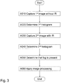
Figure 3 is a flowchart illustrating embodiments of the method in an image capturing device, -
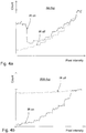
Figure 4a and Figure 4b are diagrams illustrating histograms without fog in the scene and with fog in the scene, respectively, and -
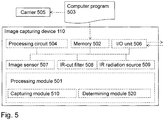
Figure 5 is a block diagram illustrating embodiments of the image capturing device. - Throughout the following description, similar reference numerals have been used to denote similar features, such as nodes, actions, modules, circuits, parts, items, elements, units or the like, when applicable. In the Figures, features that appear in some embodiments are indicated by dashed lines.
-
Figure 1 depicts an exemplifying image capturingdevice 110, such as a video recorder, asurveillance camera 120, a digital camera, asmartphone 130 including an image sensor, acar 140 including an image sensor, a wired or wireless device capable of obtaining images over a network or the like. The image capturingdevice 110 may be comprised in thesurveillance camera 120, thesmartphone 130, thecar 140 or the like. - Thus, the image capturing
device 110 is capable of processing an image. The image may have been captured by the image capturingdevice 110 itself or it may have been received from another device, which captured the image, or from a memory, such as hard drive or the like. - The image capturing
device 110 is described in more detail with reference toFigure 5 below. However, in order to provide some definitions and context for the description relating toFigure 3 below, it may be noted that the image capturingdevice 110 may comprise an image sensor for capturing images. The image sensor may be a Complementary Metal-Oxide-Semiconductor (CMOS) sensor, Charge-Coupled Device (CCD) sensor or the like. The image capturingdevice 110 may comprise an IR radiation source for emitting IR radiation. The IR radiation source may be an infrared Light Emitting Diode (LED), an IR light source, an IR illumination laser diode, black-body radiator such as halogen lamp, sodium lamp, gas discharge lamp, or the like. - Furthermore, the image capturing
device 110 may comprise an IR-cut filter for cutting IR radiation, or IR light. The IR-cut filter is movable between a first position and a second position. The IR-cut filter may be an interference filter, reflective filter, absorbing filter, hybrid reflective and absorbing filter, or the like. When the IR-cut filter is in the first position, IR radiation is prevented from reaching the image sensor. This may mean that the first position causes IR radiation incident towards the image sensor to be cut away, by the IR-cut filter, before reaching the image sensor. When the IR-cut filter is in the second position, IR radiation is allowed to fall onto the image sensor. - In order to illustrate impact of fog,
Figure 2a illustrates an exemplifying image of a scene including fog, e.g. compromised by the fog. The exemplifying image is captured without use of the IR radiation source of theimage capturing device 110. While it may be difficult to distinguish in the reproducedFigure 2a , it is here explained what is shown.Figure 2a depicts a pattern of rectangles, surrounded by a striped line. The pattern is obscured by fog and is thus barely visible inFigure 2a . -
Figure 2b illustrates a further exemplifying image of the same scene as inFigure 2a . This means that the scene also inFigure 2b includes fog. However, the further exemplifying image is captured while the scene is illuminated by the IR radiation source of theimage capturing device 110. The further exemplifying image shows the rectangles and the surrounding striped line more clearly thanks to the illumination by the IR radiation source. In this manner, theimage capturing device 110 sees through the fog by use of IR, since the IR radiation becomes less scattered, or dispersed, than visible light due to that wavelengths of IR radiation is longer than wavelengths of visible light. - Now turning to
Figure 3 , there is illustrated an exemplifying method according to embodiments herein when implemented in theimage capturing device 110 ofFigure 1 . - The
image capturing device 110 performs a method for detecting fog in a scene imaged using theimage capturing device 110. - One or more of the following actions may be performed in any suitable order.
- In order to obtain some initial information about the scene, the
image capturing device 110 captures a first image of the scene without illuminating the scene with IR radiation. - The capturing A010 of the first image may be performed with the IR-cut filter in the first position, i.e. IR radiation incident towards the image sensor of the
image capturing device 110 is cut away before reaching the image sensor. - Furthermore, since the scene is not illuminated by IR radiation, the IR radiation source may be switched off when the first image is captured. Expressed differently, the IR radiation source may be switched off during the capturing A010 of the first image.
- In order to obtain a first contrast, the
image capturing device 110 determines a first value of a measure relating to contrast for the first image. The first contrast may be a first contrast value representing contrast of the first image. This may mean that theimage capturing device 110 may determine, such as calculate, a representation of the measure relating to contrast, where the representation may be one or more values, one or more vectors, one or more matrices or the like. Accordingly, the representation, or the value for short, provides information about contrast of the first image, or generally any image, as a quantity under observation for the purpose of determining whether or not fog is present in the scene. - As previously mentioned, the measure relating to contrast of an image may be represented by a histogram, a ratio between maximum pixel count and minimum pixel count of the histogram, a sharpness of edges, a ratio of local maximum and minimum values, a so called Sobel filter for edge detection, any other suitable filter for edge detection or the like. The measure may further be represented by any quantity, determined based on an image, for the purpose of autofocus and/or contrast evaluation.
- As used herein the term "value" may refer to a graph of the measure, a vector of the measure, one or more values of the measure or the like.
- In one illustrative example, the first value of the measure may be a first histogram, e.g. a first graph representing a histogram derived from the first image. Reference is made to
Figure 4b , in which the dotted line may represent an example of the first histogram. - In more detail, the first contrast may be determined, such as calculated, as a ratio between maximum pixel count and minimum pixel count of the first histogram. Any other known measure indicating contrast may be used. Again, exemplifying measures are for example, the sharpness of edges in scene, ratio of a local maximum and minimum values within a scene, or the like.
- When the first value indicates that the first contrast of the first image less than a first threshold value, the
image capturing device 110 captures a second image of the scene while illuminating the scene with IR radiation. In this manner, theimage capturing device 110 makes an initial assumption that there is fog, but proceeds with further investigation to confirm the initial assumption. - With reference to the previously mentioned illustrative example, action A030 may mean that the
image capturing device 110 captures the second image of the scene while illuminating the scene with IR radiation, when the first histogram indicates that the first contrast of the first image is less than the first threshold value. - The first threshold value may indicate a contrast at which the first image is suspected to be compromised by fog. Thus, when the first contrast is less than the first threshold value, the
image capturing device 110 may interpret this as that the scene may be compromised by fog and the further investigation may be needed such as to ensure that there is in fact fog. At this stage, it is not clear whether the scene has a flat dynamics, i.e. low contrast or similar, or the scene is actually exposed to fog. - The capturing A030 of the second image may be performed with the IR-cut filter in the second position, i.e. IR radiation is allowed to fall onto the image sensor.
- Furthermore, in order to illuminate the scene with IR radiation, the IR radiation source may be switched on when the second image is captured. Expressed differently, the IR radiation source may be switched on during the capturing A030 of the second image.
- Similarly to action A020 above, in order to obtain a second contrast, the
image capturing device 110 determines a second value of the measure relating to contrast for the second image. The second contrast may be a second contrast value representing contrast of the second image. - With reference to the previously mentioned illustrative example, the second value of the measure may be a second histogram. Reference is again made to
Figure 4b , in which the solid line may represent an example of the second histogram. - In more detail, the second contrast may be determined, such as calculated, as a ratio between maximum pixel count and minimum pixel count of the second histogram. As mentioned above any other known measure indicating contrast may be used.
- When a difference between the first contrast and the second contrast, indicated by the second value as described in action A040, is greater than a second threshold value, the
image capturing device 110 determines that there is fog in the scene. - The second threshold value may indicate difference in contrast expected due to IR radiation. Thus, when the difference is greater than the second threshold value, the
image capturing device 110 may interpret this as that the scene may indeed be compromised by fog. Consequently, the initial assumption is confirmed. - With reference to the previously mentioned illustrative example, action A050 may mean that the
image capturing device 110 determines that there is fog in the scene, when a difference between the first contrast and the second contrast, being based on the second histogram, is greater the second threshold value. - As a first example, the
image processing device 110 may determine, such as calculate or the like, the difference as the first contrast reduced by the second contrast. The first example may be preceded by a normalization of the first and second contrasts according to any suitable measure. - As a second example, the
image processing device 110 may determine, such as calculate or the like, the difference as the first contrast divided by the second contrast. The second example may be preceded by a normalization of the first and second histograms to obtain a suitable and comparable measure. - As a third example, the
image processing device 110 may determine, such as calculate or the like, the difference based on sharpness of the first and second images. The third example may determine the sharpness by looking for sharp edges and computing their corresponding point-spread function, or it may be determined through the use of suitable filters, such as a Sobel filter or the like. - When the
image capturing device 110 has determined that there is fog in the scene, theimage capturing device 110 may apply image processing, such as contrast enhancing processing, and/or theimage capturing device 110 may decide to capture images while illuminating the scene with IR radiation. This means that theimage capturing device 110 may automatically turn on or off the contrast enhancing processing based on whether or not fog is present in the scene captured in the first and second images. - When contrast enhancing processing is applied, the difference may be used as input to the algorithm, performing the contrast enhancing processing, in order to control how heavily or hard the contrast enhancing processing is to be applied to images, such as the first image.
- Accordingly, with the embodiments according to action A060, image quality may be improved when the
image capturing device 110 has determined that there is fog in the scene, e.g. without any manual input concerning whether or not the scene is compromised or not compromised by fog. - In examples where the
image capturing device 110 may have decided to capture images while illuminating the scene with IR radiation, an advantage may be that signal to noise ratio of the captured images may be increased. A reason for this may be, as mentioned above, that the IR radiation, with wavelengths longer than wavelengths of visible light, will be scattered less. Less scattering implies less noise. Hence, signal to noise ratio may be increased. - Furthermore, some or all of actions A010 through A050 may be performed repeatedly at irregular or regular time intervals or as triggered by an event in order to allow the
image capturing device 110 to turn off the contrast enhancing processing when it is determined that the scene includes no fog and in order to allow theimage capturing device 110 to turn on the contrast enhancing processing when it is determined that the scene includes fog. The event may be that theimage capturing device 110 detects that the contrast enhancing processing appears to worsen image quality. -
Figure 4a and Figure 4b illustrate histograms of images without fog and histograms of images with fog, respectively. All histograms have been normalized against their respective maximum values, i.e. maximum pixel count, in order to better highlight difference in contrast between the histograms. In this context, it shall be said that slope of a histogram graph may be considered to be an indication of contrast. -
Figure 4a illustrates a first histogram, plotted with dotted line, and a second histogram, plotted with solid line, relating to a first scene without fog. - The first histogram is obtained from a first image captured when the first scene was not exposed to IR radiation. The second histogram is obtained from a second image captured when the first scene was exposed to IR radiation.
- Contrast may be measured in various manners. As an example, a ratio between maximal count and minimal count of pixels may be used to compare contrast in the first and second image.
- As can be seen from
Figure 4a , a difference between contrast in the first and second images is only marginal. Thus, it can be deduced that no fog is present in the first scene captured by the first and second images. Additionally, none of the first or second histograms is flat, which also is an indication of that no fog is present in the first scene. -
Figure 4b also illustrates a first histogram, plotted with dotted line, and a second histogram, plotted with solid line, relating to a second scene with fog. - The first histogram is obtained from a first image captured when the second scene was not exposed to IR radiation. The second histogram is obtained from a second image when the second scene was exposed to IR radiation.
- Again, contrast may for example be measured as a ratio between maximal count and minimal count of pixels in the first and second histograms related to the first and second images.
- As can be seen from
Figure 4b , a difference between contrast in the first and second images is quite significant. Thus, it can be deduced that fog is present in the second scene captured by the first and second images. - Hence, as given by the embodiments herein, the determination of whether or not fog is present in the scene may include two main actions.
- A first action may be to evaluate whether or not an image of a scene, i.e. the first image, has low contrast. If the contrast is low, this may be interpreted as a first indication of that there is fog in the scene of the image.
- As a second action may be to - in order to confirm the first indication that there is fog in the scene according to the first action - capture a further image, i.e. the second image, and when contrast obtained from the first and second image differs more than the second threshold value, it may be deduced that there is fog in scene. Should the scene generate an image with flat dynamics, there would be only a marginal difference in contrast between the first and second images. On the contrary, the first indication is confirmed when the difference in contrast between the first and second image is greater than the second threshold.
- With reference to
Figure 5 , a schematic block diagram of embodiments of theimage capturing device 110 ofFigure 1 is shown. - The
image capturing device 110 may comprise aprocessing module 501, such as a means for performing the methods described herein. The means may be embodied in the form of one or more hardware modules and/or one or more software modules - The
image capturing device 110 may further comprise amemory 502. The memory may comprise, such as contain or store, instructions, e.g. in the form of acomputer program 503, which may comprise computer readable code units. - According to some embodiments herein, the
image capturing device 110 and/or theprocessing module 501 comprises aprocessing circuit 504 as an exemplifying hardware module, which may comprise one or more processors. Accordingly, theprocessing module 501 may be embodied in the form of, or 'realized by', theprocessing circuit 504. The instructions may be executable by theprocessing circuit 504, whereby theimage capturing device 110 is operative to perform the methods ofFigure 3 . As another example, the instructions, when executed by theimage capturing device 110 and/or theprocessing circuit 504, may cause theimage capturing device 110 to perform the method according toFigure 3 . - In view of the above, in one example, there is provided an
image capturing device 110 for detecting fog in a scene imaged using theimage capturing device 110. Again, thememory 502 contains the instructions executable by saidprocessing circuit 504 whereby theimage capturing device 110 is operative for: - capturing a first image of the scene without illuminating the scene with IR radiation,
- determining a first value of a measure relating to contrast for the first image,
- when the first value indicates that a first contrast of the first image less than a first threshold value, capturing a second image of the scene while illuminating the scene with IR radiation,
- determining a second value of the measure relating to contrast for the second image,
- when a difference between the first contrast and a second contrast, indicated by the second value, is greater than a second threshold value, determining that there is fog in the scene.
-
Figure 5 further illustrates acarrier 505, or program carrier, which comprises thecomputer program 503 as described above. Thecarrier 505 may be one of an electronic signal, an optical signal, a radio signal and a computer readable medium. - In some embodiments, the
image capturing device 110 and/or theprocessing module 501 may comprise one or more of acapturing module 510, and a determiningmodule 520 as exemplifying hardware modules. In other examples, one or more of the aforementioned exemplifying hardware modules may be implemented as one or more software modules. - Moreover, the
image capturing device 110 and/or theprocessing module 501 comprises an Input/Output unit 506, which may be exemplified by a receiving module and/or a sending module when applicable. - Furthermore, the
image capturing device 110 may comprise animage sensor 507. - The
image processing device 110 may further comprise an IR-cut filter 508. - Additionally, the
image processing device 110 may further comprise anIR radiation source 509. - Accordingly, the
image capturing device 110 is configured for for detecting fog in a scene imaged using theimage capturing device 110. - Therefore, according to the various embodiments described above, the
image capturing device 110 and/or theprocessing module 501 and/or thecapturing module 510 is configured for capturing a first image of the scene without illuminating the scene with IR radiation. - The
image capturing device 110 and/or theprocessing module 501 and/or the determiningmodule 520, or a further determining module (not shown), is configured for determining a first value of a measure relating to contrast for the first image. - Moreover, the
image capturing device 110 and/or theprocessing module 501 and/or thecapturing module 510 is configured for capturing a second image of the scene while illuminating the scene with IR radiation, when the first value indicates that a first contrast of the first image less than a first threshold value. - The
image capturing device 110 and/or theprocessing module 501 and/or the determiningmodule 520, or a yet further determining module (not shown), is configured for determining a second value of the measure relating to contrast for the second image. - Furthermore, the
image capturing device 110 and/or theprocessing module 501 and/or the determiningmodule 520, or a still further determining module (not shown), is configured for determining that there is fog in the scene, when a difference between the first contrast and a second contrast, indicated by the second value, is greater than a second threshold value. - The first threshold value may indicate a contrast at which the first image is suspected to be compromised by fog.
- The second threshold value may indicate difference in contrast expected due to IR radiation.
- As mentioned, the
image capturing device 110 may comprise animage sensor 507 for capturing images. - The
image capturing device 110 may comprise an IR-cut filter 508 for cutting IR radiation, wherein the IR-cut filter 508 may be movable between a first position and a second position, wherein IR radiation may be prevented from reaching theimage sensor 507 when the IR-cut filter 508 is in the first position, and wherein IR radiation may be allowed to fall onto theimage sensor 507 when the IR-cut filter 508 is in the second position. - The
image capturing device 110 and/or theprocessing module 501 and/or thecapturing module 510 may be configured for capturing the first image with the IR-cut filter 508 in the first position, and/or for capturing the second image with the IR-cut filter 508 in the second position. - As mentioned, the
image capturing device 110 may comprise anIR radiation source 509 for emitting IR radiation, wherein theimage capturing device 110 and/or theprocessing module 501 and/or thecapturing module 510 may be configured to switch off theIR radiation source 509 during capturing of the first image and to switch on theIR radiation source 509 during capturing of the second image. - As used herein, the term "module" may refer to one or more functional modules, each of which may be implemented as one or more hardware modules and/or one or more software modules and/or a combined software/hardware module in a node. In some examples, the module may represent a functional unit realized as software and/or hardware of the node.
- As used herein, the term "computer program carrier", "program carrier", or "carrier", may refer to one of an electronic signal, an optical signal, a radio signal, and a computer readable medium. In some examples, the computer program carrier may exclude transitory, propagating signals, such as the electronic, optical and/or radio signal. Thus, in these examples, the computer program carrier may be a non-transitory carrier, such as a non-transitory computer readable medium.
- As used herein, the term "processing module" may include one or more hardware modules, one or more software modules or a combination thereof. Any such module, be it a hardware, software or a combined hardware-software module, may be a determining means, estimating means, capturing means, associating means, comparing means, identification means, selecting means, receiving means, sending means or the like as disclosed herein. As an example, the expression "means" may be a module corresponding to the modules listed above in conjunction with the Figures.
- As used herein, the term "software module" may refer to a software application, a Dynamic Link Library (DLL), a software component, a software object, an object according to Component Object Model (COM), a software function, a software engine, an executable binary software file or the like.
- The terms "processing module" or "processing circuit" may herein encompass a processing unit, comprising e.g. one or more processors, an Application Specific integrated Circuit (ASIC), a Field-Programmable Gate Array (FPGA) or the like. The processing circuit or the like may comprise one or more processor kernels.
- As used herein, the expression "configured to/for" may mean that a processing circuit is configured to, such as adapted to or operative to, by means of software configuration and/or hardware configuration, perform one or more of the actions described herein.
- As used herein, the term "action" may refer to an action, a step, an operation, a response, a reaction, an activity or the like. It shall be noted that an action herein may be split into two or more sub-actions as applicable. Moreover, also as applicable, it shall be noted that two or more of the actions described herein may be merged into a single action.
- As used herein, the term "memory" may refer to a hard disk, a magnetic storage medium, a portable computer diskette or disc, flash memory, random access memory (RAM) or the like. Furthermore, the term "memory" may refer to an internal register memory of a processor or the like.
- As used herein, the term "computer readable medium" may be a Universal Serial Bus (USB) memory, a DVD-disc, a Blu-ray disc, a software module that is received as a stream of data, a Flash memory, a hard drive, a memory card, such as a MemoryStick, a Multimedia Card (MMC), Secure Digital (SD) card, etc. One or more of the aforementioned examples of computer readable medium may be provided as one or more computer program products.
- As used herein, the term "computer readable code units" may be text of a computer program, parts of or an entire binary file representing a computer program in a compiled format or anything there between.
- As used herein, the terms "number" and/or "value" may be any kind of digit, such as binary, real, imaginary or rational number or the like. Moreover, "number" and/or "value" may be one or more characters, such as a letter or a string of letters. "Number" and/or "value" may also be represented by a string of bits, i.e. zeros and/or ones.
- As used herein, the terms "first", "second", "third" etc. may have been used merely to distinguish features, apparatuses, elements, units, or the like from one another unless otherwise evident from the context.
- As used herein, the term "subsequent action" may refer to that one action is performed after a preceding action, while additional actions may or may not be performed before said one action, but after the preceding action.
- As used herein, the term "set of" may refer to one or more of something. E.g. a set of devices may refer to one or more devices, a set of parameters may refer to one or more parameters or the like according to the embodiments herein.
- As used herein, the expression "in some embodiments" has been used to indicate that the features of the embodiment described may be combined with any other embodiment disclosed herein.
- Even though embodiments of the various aspects have been described, many different alterations, modifications and the like thereof will become apparent for those skilled in the art. The described embodiments are therefore not intended to limit the scope of the present disclosure.
Claims (10)
- A method, performed by an image capturing device (110), for detecting fog in a scene imaged using the image capturing device (110), wherein the method comprises:capturing (A010) a first image of the scene without illuminating the scene with IR radiation,determining (A020) a first value of a measure relating to contrast for the first image,when the first value indicates that a first contrast of the first image less than a first threshold value, capturing (A030) a second image of the scene while illuminating the scene with IR radiation,determining (A040) a second value of the measure relating to contrast for the second image,when a difference between the first contrast and a second contrast, indicated by the second value, is greater than a second threshold value, determining (A050) that there is fog in the scene.
- The method according to claim 1, wherein the first threshold value indicates a contrast at which the first image is suspected to be compromised by fog.
- The method according to any one of the preceding claims, wherein the second threshold value indicates difference in contrast expected due to IR radiation.
- The method according to any one of the preceding claims, wherein the image capturing device (110) comprises an image sensor (507) for capturing images.
- The method according to claim 4, wherein the image capturing device (110) comprises an IR-cut filter (508) for cutting IR radiation, wherein the IR-cut filter (508) is movable between a first position and a second position, wherein IR radiation is prevented from reaching the image sensor (507) when the IR-cut filter (508) is in the first position, and wherein IR radiation is allowed to fall onto the image sensor (507) when the IR-cut filter (508) is in the second position.
- The method according to the preceding claim, wherein the capturing (A010) of the first image is performed with the IR-cut filter (508) in the first position, and wherein the capturing (A030) of the second image is performed with the IR-cut filter (508) in the second position.
- The method according to claim any one of the preceding claims, wherein the image capturing device (110) comprises an IR radiation source (509) for emitting IR radiation, wherein the IR radiation source (509) is switched off during the capturing (A010) of the first image and wherein the IR radiation source (509) is switched on during the capturing (A030) of the second image.
- An image capturing device (110) configured for performing a method according to any one of claims 1-7.
- A computer program (503), comprising computer readable code units which when executed on an image capturing device (110) causes the image capturing device (110) to perform the method according to any one of claims 1-7.
- A carrier (505) comprising the computer program according to the preceding claim, wherein the carrier (505) is one of an electronic signal, an optical signal, a radio signal and a computer readable medium.
Priority Applications (6)
| Application Number | Priority Date | Filing Date | Title |
|---|---|---|---|
| EP17197933.9A EP3477548B1 (en) | 2017-10-24 | 2017-10-24 | Method and image capturing device for detecting fog in a scene |
| TW107136375A TWI690900B (en) | 2017-10-24 | 2018-10-16 | Method and image capturing device for detecting fog in a scene |
| KR1020180125880A KR102059906B1 (en) | 2017-10-24 | 2018-10-22 | Method and image capturing device for detecting fog in a scene |
| CN201811227758.3A CN109697701B (en) | 2017-10-24 | 2018-10-22 | Method and image capturing device for detecting fog in a scene |
| JP2018198810A JP6598960B2 (en) | 2017-10-24 | 2018-10-22 | Method and imaging device for fog detection in one scene |
| US16/168,834 US10467742B2 (en) | 2017-10-24 | 2018-10-24 | Method and image capturing device for detecting fog in a scene |
Applications Claiming Priority (1)
| Application Number | Priority Date | Filing Date | Title |
|---|---|---|---|
| EP17197933.9A EP3477548B1 (en) | 2017-10-24 | 2017-10-24 | Method and image capturing device for detecting fog in a scene |
Publications (2)
| Publication Number | Publication Date |
|---|---|
| EP3477548A1 true EP3477548A1 (en) | 2019-05-01 |
| EP3477548B1 EP3477548B1 (en) | 2020-02-19 |
Family
ID=60191122
Family Applications (1)
| Application Number | Title | Priority Date | Filing Date |
|---|---|---|---|
| EP17197933.9A Active EP3477548B1 (en) | 2017-10-24 | 2017-10-24 | Method and image capturing device for detecting fog in a scene |
Country Status (6)
| Country | Link |
|---|---|
| US (1) | US10467742B2 (en) |
| EP (1) | EP3477548B1 (en) |
| JP (1) | JP6598960B2 (en) |
| KR (1) | KR102059906B1 (en) |
| CN (1) | CN109697701B (en) |
| TW (1) | TWI690900B (en) |
Cited By (2)
| Publication number | Priority date | Publication date | Assignee | Title |
|---|---|---|---|---|
| CN112866636A (en) * | 2020-12-31 | 2021-05-28 | 北京文安智能技术股份有限公司 | Group fog recognition early warning method and system based on farthest visible distance and electronic equipment |
| EP4202502A4 (en) * | 2020-08-21 | 2024-02-14 | Koito Manufacturing Co., Ltd. | ON-BOARD DETECTION SYSTEMS AND TRIGGER CAMERA |
Families Citing this family (7)
| Publication number | Priority date | Publication date | Assignee | Title |
|---|---|---|---|---|
| EP3447678A1 (en) * | 2017-08-21 | 2019-02-27 | Axis AB | Method and image processing device for detecting a portion of an image |
| EP3734956B1 (en) * | 2017-12-27 | 2022-10-26 | Hangzhou Hikvision Digital Technology Co., Ltd. | Infrared light control method and device and four-eye adjustable camera |
| CN113077422B (en) * | 2021-03-22 | 2023-08-15 | 浙江大华技术股份有限公司 | Foggy image detection method, model training method and device |
| JP7647387B2 (en) * | 2021-06-25 | 2025-03-18 | 株式会社Jvcケンウッド | Image processing device, image processing method, and program |
| US11927485B2 (en) | 2021-12-17 | 2024-03-12 | Rebellion Photonics, Inc. | Systems, methods, and computer program products for detection limit determinations for hyperspectral imaging |
| CN115767209B (en) * | 2022-11-15 | 2025-08-05 | 烟台艾睿光电科技有限公司 | Infrared image acquisition control method, device, system and storage medium |
| TWI832568B (en) * | 2022-11-18 | 2024-02-11 | 廣達電腦股份有限公司 | Fog determination method, and optical apparatus |
Citations (2)
| Publication number | Priority date | Publication date | Assignee | Title |
|---|---|---|---|---|
| US20090046894A1 (en) * | 2007-08-03 | 2009-02-19 | Valeo Vision | System for the detection by a motor vehicle of a phenomenon that interferes with visibility |
| CN102539385A (en) * | 2012-01-09 | 2012-07-04 | 北京大学 | Multi-wavelength fog and haze recognition method and visibility measurement method |
Family Cites Families (5)
| Publication number | Priority date | Publication date | Assignee | Title |
|---|---|---|---|---|
| JP4463388B2 (en) * | 2000-06-29 | 2010-05-19 | 小糸工業株式会社 | Visual status measurement device |
| JP4327024B2 (en) * | 2003-08-12 | 2009-09-09 | 株式会社日立製作所 | Image processing system |
| CN104217215B (en) * | 2014-08-28 | 2017-11-28 | 哈尔滨工程大学 | A kind of classifying identification method of water surface foggy image and picture rich in detail |
| JP6361631B2 (en) * | 2015-10-29 | 2018-07-25 | Smk株式会社 | In-vehicle sensor, vehicle lamp, and vehicle |
| EP3166315A1 (en) * | 2015-11-05 | 2017-05-10 | Axis AB | A method and apparatus for controlling a degree of compression of a digital image |
-
2017
- 2017-10-24 EP EP17197933.9A patent/EP3477548B1/en active Active
-
2018
- 2018-10-16 TW TW107136375A patent/TWI690900B/en active
- 2018-10-22 KR KR1020180125880A patent/KR102059906B1/en active Active
- 2018-10-22 JP JP2018198810A patent/JP6598960B2/en active Active
- 2018-10-22 CN CN201811227758.3A patent/CN109697701B/en active Active
- 2018-10-24 US US16/168,834 patent/US10467742B2/en active Active
Patent Citations (2)
| Publication number | Priority date | Publication date | Assignee | Title |
|---|---|---|---|---|
| US20090046894A1 (en) * | 2007-08-03 | 2009-02-19 | Valeo Vision | System for the detection by a motor vehicle of a phenomenon that interferes with visibility |
| CN102539385A (en) * | 2012-01-09 | 2012-07-04 | 北京大学 | Multi-wavelength fog and haze recognition method and visibility measurement method |
Non-Patent Citations (2)
| Title |
|---|
| MARIO PAVLIC ET AL: "Image based fog detection in vehicles", INTELLIGENT VEHICLES SYMPOSIUM (IV), 2012 IEEE, IEEE, 3 June 2012 (2012-06-03), pages 1132 - 1137, XP032453047, ISBN: 978-1-4673-2119-8, DOI: 10.1109/IVS.2012.6232256 * |
| NARASIMHAN S G ET AL: "CONTRAST RESTORATION OF WEATHER DEGRADED IMAGES", IEEE TRANSACTIONS ON PATTERN ANALYSIS AND MACHINE INTELLIGENCE, IEEE COMPUTER SOCIETY, USA, vol. 25, no. 6, 1 June 2003 (2003-06-01), pages 713 - 724, XP001185045, ISSN: 0162-8828, DOI: 10.1109/TPAMI.2003.1201821 * |
Cited By (4)
| Publication number | Priority date | Publication date | Assignee | Title |
|---|---|---|---|---|
| EP4202502A4 (en) * | 2020-08-21 | 2024-02-14 | Koito Manufacturing Co., Ltd. | ON-BOARD DETECTION SYSTEMS AND TRIGGER CAMERA |
| US12363442B2 (en) | 2020-08-21 | 2025-07-15 | Koito Manufacturing Co., Ltd. | Vehicle-mounted sensing system and gated camera |
| CN112866636A (en) * | 2020-12-31 | 2021-05-28 | 北京文安智能技术股份有限公司 | Group fog recognition early warning method and system based on farthest visible distance and electronic equipment |
| CN112866636B (en) * | 2020-12-31 | 2023-06-27 | 北京文安智能技术股份有限公司 | Group fog identification early warning method and system based on farthest visible distance and electronic equipment |
Also Published As
| Publication number | Publication date |
|---|---|
| KR102059906B1 (en) | 2020-02-11 |
| TW201923709A (en) | 2019-06-16 |
| CN109697701B (en) | 2020-10-02 |
| JP2019078755A (en) | 2019-05-23 |
| TWI690900B (en) | 2020-04-11 |
| US10467742B2 (en) | 2019-11-05 |
| EP3477548B1 (en) | 2020-02-19 |
| KR20190045857A (en) | 2019-05-03 |
| JP6598960B2 (en) | 2019-10-30 |
| US20190122355A1 (en) | 2019-04-25 |
| CN109697701A (en) | 2019-04-30 |
Similar Documents
| Publication | Publication Date | Title |
|---|---|---|
| US10467742B2 (en) | Method and image capturing device for detecting fog in a scene | |
| US8503818B2 (en) | Eye defect detection in international standards organization images | |
| US20160205291A1 (en) | System and Method for Minimizing Motion Artifacts During the Fusion of an Image Bracket Based On Preview Frame Analysis | |
| US20190199898A1 (en) | Image capturing apparatus, image processing apparatus, control method, and storage medium | |
| CN111383206B (en) | Image processing method and device, electronic equipment and storage medium | |
| US10027897B2 (en) | Image processing apparatus, image processing method, and storage medium | |
| US11240439B2 (en) | Electronic apparatus and image capture apparatus capable of detecting halation, method of controlling electronic apparatus, method of controlling image capture apparatus, and storage medium | |
| US20180165515A1 (en) | Image processing apparatus, control method, and storage medium | |
| JP6525503B2 (en) | Image processing apparatus and imaging apparatus | |
| WO2006116744A1 (en) | Method and apparatus for incorporating iris color in red-eye correction | |
| KR20160037480A (en) | Method for establishing region of interest in intelligent video analytics and video analysis apparatus using the same | |
| KR102205130B1 (en) | Method and system for filtering thermal image data | |
| KR101341243B1 (en) | Apparatus and method of restoring image damaged by weather condition | |
| CN112770021B (en) | How to switch between cameras and filters | |
| US10929960B2 (en) | Method and image processing device for detecting a portion of an image | |
| EP4071660B1 (en) | Object recognition method and apparatus, electronic device and readable storage medium | |
| JP2009194786A (en) | Object detecting device, and imaging apparatus | |
| CN111161211A (en) | Image detection method and device | |
| US11272172B2 (en) | Image processing apparatus, failure detection method performed by image processing apparatus, and non-transitory recording medium | |
| KR20140073248A (en) | Device and method for reducing blooming of camera image | |
| KR20160040335A (en) | Low Power Vehicle Video Recorder with Infrared Lighting Functions for Vision Recognition Enhancement in Low Level Light Environment and Vehicle Video Recording Method thereof | |
| KR20180125278A (en) | Apparatus and method for detecting pedestrian | |
| JP2018064250A (en) | Information processing apparatus, information processing method, and program | |
| KR102793534B1 (en) | Method And Apparatus for Detecting Backlight of Image | |
| CN112183454A (en) | Image detection method and device, storage medium and terminal |
Legal Events
| Date | Code | Title | Description |
|---|---|---|---|
| STAA | Information on the status of an ep patent application or granted ep patent |
Free format text: STATUS: EXAMINATION IS IN PROGRESS |
|
| PUAI | Public reference made under article 153(3) epc to a published international application that has entered the european phase |
Free format text: ORIGINAL CODE: 0009012 |
|
| 17P | Request for examination filed |
Effective date: 20180604 |
|
| AK | Designated contracting states |
Kind code of ref document: A1 Designated state(s): AL AT BE BG CH CY CZ DE DK EE ES FI FR GB GR HR HU IE IS IT LI LT LU LV MC MK MT NL NO PL PT RO RS SE SI SK SM TR |
|
| AX | Request for extension of the european patent |
Extension state: BA ME |
|
| GRAP | Despatch of communication of intention to grant a patent |
Free format text: ORIGINAL CODE: EPIDOSNIGR1 |
|
| STAA | Information on the status of an ep patent application or granted ep patent |
Free format text: STATUS: GRANT OF PATENT IS INTENDED |
|
| INTG | Intention to grant announced |
Effective date: 20190529 |
|
| GRAS | Grant fee paid |
Free format text: ORIGINAL CODE: EPIDOSNIGR3 |
|
| GRAA | (expected) grant |
Free format text: ORIGINAL CODE: 0009210 |
|
| STAA | Information on the status of an ep patent application or granted ep patent |
Free format text: STATUS: THE PATENT HAS BEEN GRANTED |
|
| AK | Designated contracting states |
Kind code of ref document: B1 Designated state(s): AL AT BE BG CH CY CZ DE DK EE ES FI FR GB GR HR HU IE IS IT LI LT LU LV MC MK MT NL NO PL PT RO RS SE SI SK SM TR |
|
| REG | Reference to a national code |
Ref country code: CH Ref legal event code: EP |
|
| REG | Reference to a national code |
Ref country code: DE Ref legal event code: R096 Ref document number: 602017011914 Country of ref document: DE |
|
| REG | Reference to a national code |
Ref country code: AT Ref legal event code: REF Ref document number: 1235789 Country of ref document: AT Kind code of ref document: T Effective date: 20200315 |
|
| REG | Reference to a national code |
Ref country code: IE Ref legal event code: FG4D |
|
| REG | Reference to a national code |
Ref country code: SE Ref legal event code: TRGR |
|
| REG | Reference to a national code |
Ref country code: NL Ref legal event code: MP Effective date: 20200219 |
|
| PG25 | Lapsed in a contracting state [announced via postgrant information from national office to epo] |
Ref country code: NO Free format text: LAPSE BECAUSE OF FAILURE TO SUBMIT A TRANSLATION OF THE DESCRIPTION OR TO PAY THE FEE WITHIN THE PRESCRIBED TIME-LIMIT Effective date: 20200519 Ref country code: FI Free format text: LAPSE BECAUSE OF FAILURE TO SUBMIT A TRANSLATION OF THE DESCRIPTION OR TO PAY THE FEE WITHIN THE PRESCRIBED TIME-LIMIT Effective date: 20200219 Ref country code: RS Free format text: LAPSE BECAUSE OF FAILURE TO SUBMIT A TRANSLATION OF THE DESCRIPTION OR TO PAY THE FEE WITHIN THE PRESCRIBED TIME-LIMIT Effective date: 20200219 |
|
| REG | Reference to a national code |
Ref country code: LT Ref legal event code: MG4D |
|
| PG25 | Lapsed in a contracting state [announced via postgrant information from national office to epo] |
Ref country code: GR Free format text: LAPSE BECAUSE OF FAILURE TO SUBMIT A TRANSLATION OF THE DESCRIPTION OR TO PAY THE FEE WITHIN THE PRESCRIBED TIME-LIMIT Effective date: 20200520 Ref country code: IS Free format text: LAPSE BECAUSE OF FAILURE TO SUBMIT A TRANSLATION OF THE DESCRIPTION OR TO PAY THE FEE WITHIN THE PRESCRIBED TIME-LIMIT Effective date: 20200619 Ref country code: HR Free format text: LAPSE BECAUSE OF FAILURE TO SUBMIT A TRANSLATION OF THE DESCRIPTION OR TO PAY THE FEE WITHIN THE PRESCRIBED TIME-LIMIT Effective date: 20200219 Ref country code: LV Free format text: LAPSE BECAUSE OF FAILURE TO SUBMIT A TRANSLATION OF THE DESCRIPTION OR TO PAY THE FEE WITHIN THE PRESCRIBED TIME-LIMIT Effective date: 20200219 Ref country code: BG Free format text: LAPSE BECAUSE OF FAILURE TO SUBMIT A TRANSLATION OF THE DESCRIPTION OR TO PAY THE FEE WITHIN THE PRESCRIBED TIME-LIMIT Effective date: 20200519 |
|
| PG25 | Lapsed in a contracting state [announced via postgrant information from national office to epo] |
Ref country code: NL Free format text: LAPSE BECAUSE OF FAILURE TO SUBMIT A TRANSLATION OF THE DESCRIPTION OR TO PAY THE FEE WITHIN THE PRESCRIBED TIME-LIMIT Effective date: 20200219 |
|
| PG25 | Lapsed in a contracting state [announced via postgrant information from national office to epo] |
Ref country code: LT Free format text: LAPSE BECAUSE OF FAILURE TO SUBMIT A TRANSLATION OF THE DESCRIPTION OR TO PAY THE FEE WITHIN THE PRESCRIBED TIME-LIMIT Effective date: 20200219 Ref country code: EE Free format text: LAPSE BECAUSE OF FAILURE TO SUBMIT A TRANSLATION OF THE DESCRIPTION OR TO PAY THE FEE WITHIN THE PRESCRIBED TIME-LIMIT Effective date: 20200219 Ref country code: SM Free format text: LAPSE BECAUSE OF FAILURE TO SUBMIT A TRANSLATION OF THE DESCRIPTION OR TO PAY THE FEE WITHIN THE PRESCRIBED TIME-LIMIT Effective date: 20200219 Ref country code: DK Free format text: LAPSE BECAUSE OF FAILURE TO SUBMIT A TRANSLATION OF THE DESCRIPTION OR TO PAY THE FEE WITHIN THE PRESCRIBED TIME-LIMIT Effective date: 20200219 Ref country code: ES Free format text: LAPSE BECAUSE OF FAILURE TO SUBMIT A TRANSLATION OF THE DESCRIPTION OR TO PAY THE FEE WITHIN THE PRESCRIBED TIME-LIMIT Effective date: 20200219 Ref country code: RO Free format text: LAPSE BECAUSE OF FAILURE TO SUBMIT A TRANSLATION OF THE DESCRIPTION OR TO PAY THE FEE WITHIN THE PRESCRIBED TIME-LIMIT Effective date: 20200219 Ref country code: CZ Free format text: LAPSE BECAUSE OF FAILURE TO SUBMIT A TRANSLATION OF THE DESCRIPTION OR TO PAY THE FEE WITHIN THE PRESCRIBED TIME-LIMIT Effective date: 20200219 Ref country code: PT Free format text: LAPSE BECAUSE OF FAILURE TO SUBMIT A TRANSLATION OF THE DESCRIPTION OR TO PAY THE FEE WITHIN THE PRESCRIBED TIME-LIMIT Effective date: 20200712 Ref country code: SK Free format text: LAPSE BECAUSE OF FAILURE TO SUBMIT A TRANSLATION OF THE DESCRIPTION OR TO PAY THE FEE WITHIN THE PRESCRIBED TIME-LIMIT Effective date: 20200219 |
|
| REG | Reference to a national code |
Ref country code: AT Ref legal event code: MK05 Ref document number: 1235789 Country of ref document: AT Kind code of ref document: T Effective date: 20200219 |
|
| REG | Reference to a national code |
Ref country code: DE Ref legal event code: R097 Ref document number: 602017011914 Country of ref document: DE |
|
| PLBE | No opposition filed within time limit |
Free format text: ORIGINAL CODE: 0009261 |
|
| STAA | Information on the status of an ep patent application or granted ep patent |
Free format text: STATUS: NO OPPOSITION FILED WITHIN TIME LIMIT |
|
| 26N | No opposition filed |
Effective date: 20201120 |
|
| PG25 | Lapsed in a contracting state [announced via postgrant information from national office to epo] |
Ref country code: IT Free format text: LAPSE BECAUSE OF FAILURE TO SUBMIT A TRANSLATION OF THE DESCRIPTION OR TO PAY THE FEE WITHIN THE PRESCRIBED TIME-LIMIT Effective date: 20200219 Ref country code: AT Free format text: LAPSE BECAUSE OF FAILURE TO SUBMIT A TRANSLATION OF THE DESCRIPTION OR TO PAY THE FEE WITHIN THE PRESCRIBED TIME-LIMIT Effective date: 20200219 |
|
| PG25 | Lapsed in a contracting state [announced via postgrant information from national office to epo] |
Ref country code: PL Free format text: LAPSE BECAUSE OF FAILURE TO SUBMIT A TRANSLATION OF THE DESCRIPTION OR TO PAY THE FEE WITHIN THE PRESCRIBED TIME-LIMIT Effective date: 20200219 Ref country code: SI Free format text: LAPSE BECAUSE OF FAILURE TO SUBMIT A TRANSLATION OF THE DESCRIPTION OR TO PAY THE FEE WITHIN THE PRESCRIBED TIME-LIMIT Effective date: 20200219 |
|
| REG | Reference to a national code |
Ref country code: CH Ref legal event code: PL |
|
| PG25 | Lapsed in a contracting state [announced via postgrant information from national office to epo] |
Ref country code: MC Free format text: LAPSE BECAUSE OF FAILURE TO SUBMIT A TRANSLATION OF THE DESCRIPTION OR TO PAY THE FEE WITHIN THE PRESCRIBED TIME-LIMIT Effective date: 20200219 Ref country code: LU Free format text: LAPSE BECAUSE OF NON-PAYMENT OF DUE FEES Effective date: 20201024 |
|
| REG | Reference to a national code |
Ref country code: BE Ref legal event code: MM Effective date: 20201031 |
|
| PG25 | Lapsed in a contracting state [announced via postgrant information from national office to epo] |
Ref country code: CH Free format text: LAPSE BECAUSE OF NON-PAYMENT OF DUE FEES Effective date: 20201031 Ref country code: BE Free format text: LAPSE BECAUSE OF NON-PAYMENT OF DUE FEES Effective date: 20201031 Ref country code: LI Free format text: LAPSE BECAUSE OF NON-PAYMENT OF DUE FEES Effective date: 20201031 |
|
| PG25 | Lapsed in a contracting state [announced via postgrant information from national office to epo] |
Ref country code: IE Free format text: LAPSE BECAUSE OF NON-PAYMENT OF DUE FEES Effective date: 20201024 |
|
| REG | Reference to a national code |
Ref country code: DE Ref legal event code: R079 Ref document number: 602017011914 Country of ref document: DE Free format text: PREVIOUS MAIN CLASS: G06K0009200000 Ipc: G06V0030140000 |
|
| PG25 | Lapsed in a contracting state [announced via postgrant information from national office to epo] |
Ref country code: TR Free format text: LAPSE BECAUSE OF FAILURE TO SUBMIT A TRANSLATION OF THE DESCRIPTION OR TO PAY THE FEE WITHIN THE PRESCRIBED TIME-LIMIT Effective date: 20200219 Ref country code: MT Free format text: LAPSE BECAUSE OF FAILURE TO SUBMIT A TRANSLATION OF THE DESCRIPTION OR TO PAY THE FEE WITHIN THE PRESCRIBED TIME-LIMIT Effective date: 20200219 Ref country code: CY Free format text: LAPSE BECAUSE OF FAILURE TO SUBMIT A TRANSLATION OF THE DESCRIPTION OR TO PAY THE FEE WITHIN THE PRESCRIBED TIME-LIMIT Effective date: 20200219 |
|
| PG25 | Lapsed in a contracting state [announced via postgrant information from national office to epo] |
Ref country code: MK Free format text: LAPSE BECAUSE OF FAILURE TO SUBMIT A TRANSLATION OF THE DESCRIPTION OR TO PAY THE FEE WITHIN THE PRESCRIBED TIME-LIMIT Effective date: 20200219 Ref country code: AL Free format text: LAPSE BECAUSE OF FAILURE TO SUBMIT A TRANSLATION OF THE DESCRIPTION OR TO PAY THE FEE WITHIN THE PRESCRIBED TIME-LIMIT Effective date: 20200219 |
|
| P01 | Opt-out of the competence of the unified patent court (upc) registered |
Effective date: 20230505 |
|
| PGFP | Annual fee paid to national office [announced via postgrant information from national office to epo] |
Ref country code: GB Payment date: 20250923 Year of fee payment: 9 |
|
| PGFP | Annual fee paid to national office [announced via postgrant information from national office to epo] |
Ref country code: FR Payment date: 20250923 Year of fee payment: 9 |
|
| PGFP | Annual fee paid to national office [announced via postgrant information from national office to epo] |
Ref country code: SE Payment date: 20250923 Year of fee payment: 9 |
|
| PGFP | Annual fee paid to national office [announced via postgrant information from national office to epo] |
Ref country code: DE Payment date: 20250923 Year of fee payment: 9 |