EP3477327A1 - Mobile communication device and method for operating a mobile communication device - Google Patents
Mobile communication device and method for operating a mobile communication device Download PDFInfo
- Publication number
- EP3477327A1 EP3477327A1 EP17198614.4A EP17198614A EP3477327A1 EP 3477327 A1 EP3477327 A1 EP 3477327A1 EP 17198614 A EP17198614 A EP 17198614A EP 3477327 A1 EP3477327 A1 EP 3477327A1
- Authority
- EP
- European Patent Office
- Prior art keywords
- signal strength
- mobile communication
- communication device
- receiver
- value
- Prior art date
- Legal status (The legal status is an assumption and is not a legal conclusion. Google has not performed a legal analysis and makes no representation as to the accuracy of the status listed.)
- Granted
Links
Images


Classifications
-
- G—PHYSICS
- G01—MEASURING; TESTING
- G01S—RADIO DIRECTION-FINDING; RADIO NAVIGATION; DETERMINING DISTANCE OR VELOCITY BY USE OF RADIO WAVES; LOCATING OR PRESENCE-DETECTING BY USE OF THE REFLECTION OR RERADIATION OF RADIO WAVES; ANALOGOUS ARRANGEMENTS USING OTHER WAVES
- G01S11/00—Systems for determining distance or velocity not using reflection or reradiation
- G01S11/02—Systems for determining distance or velocity not using reflection or reradiation using radio waves
- G01S11/06—Systems for determining distance or velocity not using reflection or reradiation using radio waves using intensity measurements
-
- G—PHYSICS
- G01—MEASURING; TESTING
- G01S—RADIO DIRECTION-FINDING; RADIO NAVIGATION; DETERMINING DISTANCE OR VELOCITY BY USE OF RADIO WAVES; LOCATING OR PRESENCE-DETECTING BY USE OF THE REFLECTION OR RERADIATION OF RADIO WAVES; ANALOGOUS ARRANGEMENTS USING OTHER WAVES
- G01S5/00—Position-fixing by co-ordinating two or more direction or position line determinations; Position-fixing by co-ordinating two or more distance determinations
- G01S5/02—Position-fixing by co-ordinating two or more direction or position line determinations; Position-fixing by co-ordinating two or more distance determinations using radio waves
- G01S5/0205—Details
- G01S5/021—Calibration, monitoring or correction
-
- G—PHYSICS
- G01—MEASURING; TESTING
- G01S—RADIO DIRECTION-FINDING; RADIO NAVIGATION; DETERMINING DISTANCE OR VELOCITY BY USE OF RADIO WAVES; LOCATING OR PRESENCE-DETECTING BY USE OF THE REFLECTION OR RERADIATION OF RADIO WAVES; ANALOGOUS ARRANGEMENTS USING OTHER WAVES
- G01S5/00—Position-fixing by co-ordinating two or more direction or position line determinations; Position-fixing by co-ordinating two or more distance determinations
- G01S5/02—Position-fixing by co-ordinating two or more direction or position line determinations; Position-fixing by co-ordinating two or more distance determinations using radio waves
- G01S5/14—Determining absolute distances from a plurality of spaced points of known location
Definitions
- the invention relates to a mobile communication device. Further, the present invention relates to a method for operating a mobile communication device.
- Modern mobile communication devices allow applications to read the signal strength of incoming wireless signals. This for example allows determining the most proximate communication partners or even determining a position of the mobile device based on triangulation techniques.
- a reception strength, RX value, and/or a Received Signal Strength Indicator, RSSI value may be provided as signal strength measure. Both the RX value and the RSSI value are indications of the power level being received by the antenna of the mobile device. The difference between the RX value and the RSSI value is that the RX value is measured in milliwat (mW) or decibel-milliwat (dBm) whereas the RSSI value is provided as a percentage. The higher the RSSI value, the stronger the signal is received. Unlike the RX value, the RSSI value is a relative value and the exact process of determining the RSSI value is defined by the chip manufacturer of the respective wireless receiver/transceiver chip. This leads to the same RSSI values in different chip sets referring to different absolute signal strength values. This makes distance and position determination difficult.
- the present invention provides a mobile communication device with the features of claim 1 and a method for operating a mobile communication device with the features of claim 6.
- the present invention is based on the finding that in the field a large variation of RF devices and RF chipsets exists that each define the RSSI value according to their own internal algorithms. This means that e.g. the same RSSI value on two different cell phones with two different chipsets may mean two different absolute signal strengths. Further, it is in most cell phones not possible to directly access the RX value. However, even if this would be possible, the RX value would not be comparable between different chipsets, since they may have different receiver sensitivities and gain values in the receiving signal chain. For example, in RF communications like Bluetooth, manufacturer A could provide a maximum RSSI value of 100 while Manufacturer B may provide RSSI values anywhere from 0 to 127.
- the present invention therefore provides the mobile communication device with the receiver and the normalization unit.
- the receiver may be a standard receiver that provides a signal strength value, like e.g. a value that indicates the received signal strength in mW or dBm.
- the signal strength value may then be further processed by the normalization unit to provide a normalized signal strength indication.
- the normalization unit may use parameters of the receiver, the receiver chip set or the full reception signal chain to calculate the normalized signal strength indication.
- the normalized signal strength indication may e.g. be provided as a value between 0 and 100, wherein 0 refers to the lowest signal strength and 100 refers to the maximum signal strength.
- the normalized signal strength indication provides a comparable value for the strength of a received signal over all different chipsets of different chipset manufacturers. Therefore, with the normalized signal strength indication an improved and more accurate distance approximation will be possible. With the improved distance calculation in turn an improved position determination using triangulation techniques will also be possible.
- the receiver and the normalization unit may be provided as separated logic units or circuits in the mobile device. It is however also understood, that the normalization unit may be integrated into the receiver.
- the normalization unit may e.g. be integrated into a logic unit of the receiver that usually provides the signal strength value. Further, the receiver and the normalization unit may be integrated in a system-on-chip that may e.g. form the basis of the mobile communication device's RF capabilities.
- the normalization unit may e.g. be provided as firmware or software routine of an operating system in the mobile communication device that has access to the low level peripherals and may receive the signal strength value from the receiver.
- the normalization unit may be configured to calculate the normalized signal strength indication based on the signal strength value provided by the receiver and a maximum possible signal strength value and a minimum possible signal strength value and a sensitivity of the receiver.
- the sensitivity of the receiver or RF sensitivity is one of the key specifications of any radio receiver whether it is used for Wi-Fi, cellular telecommunications broadcast or any other form of wireless communications.
- the manufacturer of the respective receiver or reception signal chain may therefore provide the sensitivity of the receiver to the normalization unit as well as the maximum possible signal strength value maxRX, and the minimum possible signal strength value minRX.
- the normalization unit may comprise a respective parameter memory to store the sensitivity of the receiver as well as the maximum possible signal strength value maxRX, and the minimum possible signal strength value minRX.
- the sensitivity of the receiver may comprise an average sensitivity of the receiver or the sensitivity of the receiver may comprise a measured sensitivity value.
- the sensitivity of the receiver may e.g. be stored in the normalization unit as an average sensitivity value for the respective type of receiver. This value may e.g. be determined on samples of the mobile communication device during development of the mobile communication device. If an average value for the sensitivity is defined, no further parameterization step will be necessary during production of the mobile device.
- the manufacturer of the receiver or the mobile device may measure the sensitivity of the receiver individually for every single device.
- the measured sensitivity may then e.g. be provided to the normalization unit during a parameterization step in the production of the normalization unit or the mobile communication device.
- the mobile communication device may comprise a mapping unit configured to perform a mapping of the normalized signal strength indication to a distance and provide a respective distance value.
- the mapping unit may e.g. convert a normalized signal strength indication that is provided in dBm or mW into a distance value that may e.g. be provided in centimeters, cm, or meters, m.
- the mapping may e.g. be performed using a respective formula or using a look-up-table, LUT, that provides the respective mapping.
- the normalized signal strength indication and the distance may have an inverse relationship. This means that a lower normalized signal strength indication indicates a higher distance and vice versa.
- mapping unit may be integrated into the normalization unit.
- the mobile communication device may comprise an application interface configured to provide the normalized signal strength indication to an application that is executed on a processor of the mobile communication device.
- the application interface may e.g. be provided as an API in the operating system of the mobile communication device.
- This API may allow application programs to access the normalized signal strength indication or the already mapped distance value. Together with e.g. identifiers or known positions of communication partners the application may then easily determine a position of the mobile communication device.
- Fig. 1 shows a block diagram of a mobile communication device 100.
- the mobile communication device 100 comprises an antenna 105 that is coupled to a receiver 109.
- the receiver 109 is coupled to a normalization unit 111.
- Around the mobile communication device 100 there are provided three exemplary further mobile communication devices 101, 102, 103 that emit wireless signals 106, 107, 108.
- the antenna 105 receives the wireless signals 106, 107, 108 and provides the received wireless signals 106, 107, 108 to the receiver 109.
- the receiver 109 determines a signal strength of the received wireless signals 106, 107, 108 and provides respective signal strength values 110 for the single received wireless signals 106, 107, 108.
- the normalization unit 111 normalizes the signal strength values 110 and provides respective normalized signal strength indications 112.
- the receiver 109 may perform any further signal handling and signal processing that is necessary to perform the communication functions of the mobile communication device 100.
- the receiver 109 may e.g. comprise analog and/or digital circuitry e.g. filters, amplifiers, attenuators, A/D converters and the like.
- the mobile communication device 100 may e.g. comprise a processor that executes a firmware, an operating system and/or applications. Such applications may e.g. comprise position determination applications that determine the position of the mobile communication device 100 based on received Bluetooth signals.
- the further mobile communication devices 101, 102, 103 may e.g. be Bluetooth beacons with a known position.
- the firmware, operating system or software may now determine the distance between the mobile communication device 100 and the further mobile communication devices 101, 102, 103 based on the normalized signal strength indication 112. If the absolute positions of the further mobile communication devices 101, 102, 103 are known, it may be enough to calculate the relative position of the mobile communication device 100 with relation to the three further mobile communication devices 101, 102, 103 to be able to determine the absolute position of the mobile communication device 100.
- the firmware, operating system or software may e.g. perform respective triangulation techniques to determine the position of the mobile communication device 100.
- the receiver 109 may e.g. provide additional information with the signal strength value 110.
- the receiver 109 may e.g. further indicate the source of the received wireless signals 106, 107, 108, e.g. one of the further mobile communication devices 101, 102, 103.
- the receiver 109 may also provide the data transmitted in the wireless signals 106, 107, 108.
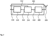
- Fig. 2 shows a block diagram of a mobile communication device 200.
- the mobile communication device 200 is based on the mobile communication device 100.
- the mobile communication device 200 therefore comprises an antenna 205 that is coupled to a receiver 209.
- the receiver 209 is coupled to a normalization unit 211.
- the mobile communication device 200 comprises a mapping unit 215.
- the antenna 205 receives wireless signals and provides the received wireless signals to the receiver 209.
- the receiver 209 determines a signal strength of the received wireless signals and provides a respective signal strength value 210.
- the normalization unit 211 normalizes the signal strength value 210 and provide a respective normalized signal strength indication 212.
- the mapping unit 215 processes the normalized signal strength indication 212 and determines a corresponding distance value 216.
- the distance value 216 is a distance, e.g. in meter, that is the corresponding distance to the source of the received wireless signal.
- the mapping unit 215 may e.g. perform a formula based mapping.
- the mapping unit 215 may comprise a look-up table that maps the normalized signal strength indication 212 to the respective distance.
- mapping unit 215 may easily determine the relative location of the mobile communication device 200 with regard to the signal sources.
- the normalized signal strength indication 212 may also be provided bypassing the mapping unit 215 to e.g. a firmware, an operating system or an application.
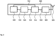
- Fig. 3 shows a block diagram of a mobile communication device 300.
- the mobile communication device 300 is based on the mobile communication device 200. Therefore, the mobile communication device 300 also comprises an antenna 305 that is coupled to a receiver 309.
- the receiver 309 is coupled to a normalization unit 311.
- the normalization unit 311 provides the normalized signal strength indication 312 to the mapping unit 215.
- an application interface 320 is provided in the mobile communication device 300.
- the application interface 320 provides simple access by standardized access functions for applications that may e.g. run in an operating system of the mobile communication device 300.
- Fig. 4 shows a flow diagram of a method for operating a mobile communication device 100, 101, 102, 103, 104, 200, 300.
- the method comprises receiving S1 wireless signals 106, 107, 108, determining S2 a signal strength of the received wireless signals 106, 107, 108 and providing a respective signal strength value 110, 210, 310, and normalizing S3 the signal strength value 110, 210, 310 and providing a respective normalized signal strength indication 112, 212, 312.
- Normalizing S3 may e.g. comprise calculating the normalized signal strength indication 112, 212, 312 based on the signal strength value 110, 210, 310 provided by the receiver 109, 209, 309 and a maximum possible signal strength value 110, 210, 310 and a minimum possible signal strength value 110, 210, 310 and a sensitivity of the receiver 109, 209, 309.
- the sensitivity of the receiver 109, 209, 309 may e.g. comprises an average sensitivity of the receiver 109, 209, 309, i.e. the type of receiver, or a measured sensitivity value of the specific receiver 109, 209, 309.
- the method may also comprise mapping the normalized signal strength indication 112, 212, 312 to a distance and providing a respective distance value 216, 316.
- the normalized signal strength indication 112, 212, 312 may be provided to an application that is executed on a processor of the mobile communication device 100, 101, 102, 103, 104, 200, 300 via an application interface 320.
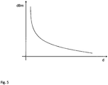
- Fig. 5 shows a diagram of a possible normalized signal strength indication to distance mapping.
- the mapping in the diagram of Fig. 5 shows that the maximum normalized signal strength indication 112, 212, 312 represents the shortest distance. The smaller the value of the normalized signal strength indication 112, 212, 312 the larger the distance.
- the diagram of Fig. 5 only serves to clarify the concept of the present invention. Therefore, no absolute values are provided at the axis of the diagram. It is understood, that the absolute values of the mapping may vary depending on the respective application. The mapping may e.g. be different for Bluetooth devices than for WiFi or UMTS devices or the like.
- the present invention provides a mobile communication device 100, 101, 102, 103, 104, 200, 300 for wireless communication, the mobile communication device 100, 101, 102, 103, 104, 200, 300 comprising an antenna 105, 205, 305 configured to receive wireless signals 106, 107, 108, a receiver 109, 209, 309 that is coupled to the antenna 105, 205, 305 and that is configured to determine a signal strength of the received wireless signals 106, 107, 108 and provide a respective signal strength value 110, 210, 310, and a normalization unit 111, 211, 311 that is configured to normalize the signal strength value 110, 210, 310 and provide a respective normalized signal strength indication 112, 212, 312. Further, the present invention provides a method for operating a mobile communication device 100, 101, 102, 103, 104, 200, 300.
Landscapes
- Physics & Mathematics (AREA)
- Engineering & Computer Science (AREA)
- General Physics & Mathematics (AREA)
- Radar, Positioning & Navigation (AREA)
- Remote Sensing (AREA)
- Mobile Radio Communication Systems (AREA)
- Transceivers (AREA)
Abstract
Description
- The invention relates to a mobile communication device. Further, the present invention relates to a method for operating a mobile communication device.
- Although applicable to any wireless mobile device, the present invention will mainly be described in conjunction with mobile communication devices, like e.g. cell phones.
- Modern mobile communication devices allow applications to read the signal strength of incoming wireless signals. This for example allows determining the most proximate communication partners or even determining a position of the mobile device based on triangulation techniques.
- In mobile devices usually a reception strength, RX value, and/or a Received Signal Strength Indicator, RSSI value, may be provided as signal strength measure. Both the RX value and the RSSI value are indications of the power level being received by the antenna of the mobile device. The difference between the RX value and the RSSI value is that the RX value is measured in milliwat (mW) or decibel-milliwat (dBm) whereas the RSSI value is provided as a percentage. The higher the RSSI value, the stronger the signal is received. Unlike the RX value, the RSSI value is a relative value and the exact process of determining the RSSI value is defined by the chip manufacturer of the respective wireless receiver/transceiver chip. This leads to the same RSSI values in different chip sets referring to different absolute signal strength values. This makes distance and position determination difficult.
- Accordingly, there is a need for improving signal strength determination in mobile devices.
- The present invention provides a mobile communication device with the features of
claim 1 and a method for operating a mobile communication device with the features of claim 6. - Accordingly, it is provided:
- A mobile communication device for wireless communication, the mobile communication device comprising an antenna configured to receive wireless signals, a receiver that is coupled to the antenna and that is configured to determine a signal strength of the received wireless signals and provide a respective signal strength value, and a normalization unit that is configured to normalize the signal strength value and provide a respective normalized signal strength indication.
- Further, it is provided:
- A method for operating a mobile communication device, the method comprising receiving wireless signals, determining a signal strength of the received wireless signals and providing a respective signal strength value, and normalizing the signal strength value and providing a respective normalized signal strength indication.
- The present invention is based on the finding that in the field a large variation of RF devices and RF chipsets exists that each define the RSSI value according to their own internal algorithms. This means that e.g. the same RSSI value on two different cell phones with two different chipsets may mean two different absolute signal strengths. Further, it is in most cell phones not possible to directly access the RX value. However, even if this would be possible, the RX value would not be comparable between different chipsets, since they may have different receiver sensitivities and gain values in the receiving signal chain. For example, in RF communications like Bluetooth, manufacturer A could provide a maximum RSSI value of 100 while Manufacturer B may provide RSSI values anywhere from 0 to 127.
- The present invention therefore provides the mobile communication device with the receiver and the normalization unit.
- The receiver may be a standard receiver that provides a signal strength value, like e.g. a value that indicates the received signal strength in mW or dBm. The signal strength value may then be further processed by the normalization unit to provide a normalized signal strength indication.
- The normalization unit may use parameters of the receiver, the receiver chip set or the full reception signal chain to calculate the normalized signal strength indication. The normalized signal strength indication may e.g. be provided as a value between 0 and 100, wherein 0 refers to the lowest signal strength and 100 refers to the maximum signal strength.
- The normalized signal strength indication provides a comparable value for the strength of a received signal over all different chipsets of different chipset manufacturers. Therefore, with the normalized signal strength indication an improved and more accurate distance approximation will be possible. With the improved distance calculation in turn an improved position determination using triangulation techniques will also be possible.
- It is understood, that the receiver and the normalization unit may be provided as separated logic units or circuits in the mobile device. It is however also understood, that the normalization unit may be integrated into the receiver. The normalization unit may e.g. be integrated into a logic unit of the receiver that usually provides the signal strength value. Further, the receiver and the normalization unit may be integrated in a system-on-chip that may e.g. form the basis of the mobile communication device's RF capabilities. As an alternative, the normalization unit may e.g. be provided as firmware or software routine of an operating system in the mobile communication device that has access to the low level peripherals and may receive the signal strength value from the receiver.
- Further embodiments of the present invention are subject of the further subclaims and of the following description, referring to the drawings.
- In an embodiment, the normalization unit may be configured to calculate the normalized signal strength indication based on the signal strength value provided by the receiver and a maximum possible signal strength value and a minimum possible signal strength value and a sensitivity of the receiver.
- The normalized signal strength indication, nss, may e.g. be calculated as:


- The sensitivity of the receiver or RF sensitivity is one of the key specifications of any radio receiver whether it is used for Wi-Fi, cellular telecommunications broadcast or any other form of wireless communications. The manufacturer of the respective receiver or reception signal chain may therefore provide the sensitivity of the receiver to the normalization unit as well as the maximum possible signal strength value maxRX, and the minimum possible signal strength value minRX.
- It is understood, that the normalization unit may comprise a respective parameter memory to store the sensitivity of the receiver as well as the maximum possible signal strength value maxRX, and the minimum possible signal strength value minRX.
- In another embodiment, the sensitivity of the receiver may comprise an average sensitivity of the receiver or the sensitivity of the receiver may comprise a measured sensitivity value.
- The sensitivity of the receiver may e.g. be stored in the normalization unit as an average sensitivity value for the respective type of receiver. This value may e.g. be determined on samples of the mobile communication device during development of the mobile communication device. If an average value for the sensitivity is defined, no further parameterization step will be necessary during production of the mobile device.
- As alternative, the manufacturer of the receiver or the mobile device may measure the sensitivity of the receiver individually for every single device. The measured sensitivity may then e.g. be provided to the normalization unit during a parameterization step in the production of the normalization unit or the mobile communication device.
- In an embodiment, the mobile communication device may comprise a mapping unit configured to perform a mapping of the normalized signal strength indication to a distance and provide a respective distance value.
- The mapping unit may e.g. convert a normalized signal strength indication that is provided in dBm or mW into a distance value that may e.g. be provided in centimeters, cm, or meters, m. The mapping may e.g. be performed using a respective formula or using a look-up-table, LUT, that provides the respective mapping.
- It is understood, that the normalized signal strength indication and the distance may have an inverse relationship. This means that a lower normalized signal strength indication indicates a higher distance and vice versa.
- It is understood, that the mapping unit may be integrated into the normalization unit.
- In a further embodiment, the mobile communication device may comprise an application interface configured to provide the normalized signal strength indication to an application that is executed on a processor of the mobile communication device.
- The application interface may e.g. be provided as an API in the operating system of the mobile communication device. This API may allow application programs to access the normalized signal strength indication or the already mapped distance value. Together with e.g. identifiers or known positions of communication partners the application may then easily determine a position of the mobile communication device.
- For a more complete understanding of the present invention and advantages thereof, reference is now made to the following description taken in conjunction with the accompanying drawings. The invention is explained in more detail below using exemplary embodiments which are specified in the schematic figures of the drawings, in which:
- Fig. 1
- shows a block diagram of an embodiment of a mobile communication device according to the present invention;
- Fig. 2
- shows a block diagram of another embodiment of a mobile communication device according to the present invention;
- Fig. 3
- shows a block diagram of another embodiment of a mobile communication device according to the present invention;
- Fig. 4
- shows a flow diagram of an embodiment of a method according to the present invention; and
- Fig. 5
- shows a diagram of a possible normalized signal strength indication to distance mapping according to an embodiment of the present invention.
- In the figures like reference signs denote like elements unless stated otherwise.
-
Fig. 1 shows a block diagram of amobile communication device 100. Themobile communication device 100 comprises anantenna 105 that is coupled to areceiver 109. Thereceiver 109 is coupled to anormalization unit 111. Around themobile communication device 100 there are provided three exemplary furthermobile communication devices - The
antenna 105 receives the wireless signals 106, 107, 108 and provides the receivedwireless signals receiver 109. Thereceiver 109 determines a signal strength of the receivedwireless signals wireless signals normalization unit 111 normalizes the signal strength values 110 and provides respective normalizedsignal strength indications 112. - It is understood, that the
receiver 109 may perform any further signal handling and signal processing that is necessary to perform the communication functions of themobile communication device 100. To this end thereceiver 109 may e.g. comprise analog and/or digital circuitry e.g. filters, amplifiers, attenuators, A/D converters and the like. - The
mobile communication device 100 may e.g. comprise a processor that executes a firmware, an operating system and/or applications. Such applications may e.g. comprise position determination applications that determine the position of themobile communication device 100 based on received Bluetooth signals. The furthermobile communication devices - The firmware, operating system or software may now determine the distance between the
mobile communication device 100 and the furthermobile communication devices signal strength indication 112. If the absolute positions of the furthermobile communication devices mobile communication device 100 with relation to the three furthermobile communication devices mobile communication device 100. The firmware, operating system or software may e.g. perform respective triangulation techniques to determine the position of themobile communication device 100. - It is understood, that the
receiver 109 may e.g. provide additional information with thesignal strength value 110. Thereceiver 109 may e.g. further indicate the source of the receivedwireless signals mobile communication devices receiver 109 may also provide the data transmitted in the wireless signals 106, 107, 108. -
Fig. 2 shows a block diagram of amobile communication device 200. Themobile communication device 200 is based on themobile communication device 100. Themobile communication device 200 therefore comprises anantenna 205 that is coupled to areceiver 209. Thereceiver 209 is coupled to anormalization unit 211. In addition, themobile communication device 200 comprises amapping unit 215. - It is understood, that as explained for the
mobile communication device 100 in themobile communication device 200 theantenna 205 receives wireless signals and provides the received wireless signals to thereceiver 209. Thereceiver 209 determines a signal strength of the received wireless signals and provides a respectivesignal strength value 210. Then thenormalization unit 211 normalizes thesignal strength value 210 and provide a respective normalizedsignal strength indication 212. - In addition, in the
mobile communication device 200, themapping unit 215 processes the normalizedsignal strength indication 212 and determines acorresponding distance value 216. Thedistance value 216 is a distance, e.g. in meter, that is the corresponding distance to the source of the received wireless signal. Themapping unit 215 may e.g. perform a formula based mapping. As an alternative, themapping unit 215 may comprise a look-up table that maps the normalizedsignal strength indication 212 to the respective distance. - If the distances of the
mobile communication device 200 to different signal sources are directly provided by themapping unit 215, e.g. to a firmware, an operating system or an application, these may easily determine the relative location of themobile communication device 200 with regard to the signal sources. - It can be seen in the
mobile communication device 200, that the normalizedsignal strength indication 212 may also be provided bypassing themapping unit 215 to e.g. a firmware, an operating system or an application. -
Fig. 3 shows a block diagram of amobile communication device 300. Themobile communication device 300 is based on themobile communication device 200. Therefore, themobile communication device 300 also comprises anantenna 305 that is coupled to areceiver 309. Thereceiver 309 is coupled to anormalization unit 311. Thenormalization unit 311 provides the normalizedsignal strength indication 312 to themapping unit 215. In addition, anapplication interface 320 is provided in themobile communication device 300. - The
application interface 320 provides simple access by standardized access functions for applications that may e.g. run in an operating system of themobile communication device 300. - For sake of clarity in the following description of the method based
Fig. 4 the reference signs used above in the description of apparatus basedFigs. 1 - 3 will be maintained. -
Fig. 4 shows a flow diagram of a method for operating amobile communication device - The method comprises receiving S1 wireless signals 106, 107, 108, determining S2 a signal strength of the received
wireless signals signal strength value signal strength value signal strength indication - Normalizing S3 may e.g. comprise calculating the normalized
signal strength indication signal strength value receiver signal strength value signal strength value receiver - The normalized signal strength indication, nss, 112, 212, 312 may e.g. be calculated as:


- The sensitivity of the
receiver receiver specific receiver - The method may also comprise mapping the normalized
signal strength indication respective distance value - In addition, the normalized
signal strength indication mobile communication device application interface 320. -
Fig. 5 shows a diagram of a possible normalized signal strength indication to distance mapping. - The mapping in the diagram of
Fig. 5 shows that the maximum normalizedsignal strength indication signal strength indication - The diagram of
Fig. 5 only serves to clarify the concept of the present invention. Therefore, no absolute values are provided at the axis of the diagram. It is understood, that the absolute values of the mapping may vary depending on the respective application. The mapping may e.g. be different for Bluetooth devices than for WiFi or UMTS devices or the like. - Although specific embodiments have been illustrated and described herein, it will be appreciated by those of ordinary skill in the art that a variety of alternate and/or equivalent implementations exist. It should be appreciated that the exemplary embodiment or exemplary embodiments are only examples, and are not intended to limit the scope, applicability, or configuration in any way. Rather, the foregoing summary and detailed description will provide those skilled in the art with a convenient road map for implementing at least one exemplary embodiment, it being understood that various changes may be made in the function and arrangement of elements described in an exemplary embodiment without departing from the scope as set forth in the appended claims and their legal equivalents. Generally, this application is intended to cover any adaptations or variations of the specific embodiments discussed herein.
- Thus, the present invention provides a
mobile communication device mobile communication device antenna wireless signals receiver antenna wireless signals signal strength value normalization unit signal strength value signal strength indication mobile communication device -
- 100, 101, 102, 103, 104, 200, 300
- mobile communication device
- 105, 205, 305
- antenna
- 106, 107, 108
- wireless signal
- 109, 209, 309
- receiver
- 110, 210, 310
- signal strength value
- 111, 211, 311
- normalization unit
- 112, 212, 312
- normalized signal strength indication
- 215, 315
- mapping unit
- 216, 316
- distance value
- 320
- application interface
Claims (10)
- Mobile communication device (100, 101, 102, 103, 104, 200, 300) for wireless communication, the mobile communication device (100, 101, 102, 103, 104, 200, 300) comprising:an antenna (105, 205, 305) configured to receive wireless signals (106, 107, 108),a receiver (109, 209, 309) that is coupled to the antenna (105, 205, 305) and that is configured to determine a signal strength of the received wireless signals (106, 107, 108) and provide a respective signal strength value (110, 210, 310), anda normalization unit (111, 211, 311) that is configured to normalize the signal strength value (110, 210, 310) and provide a respective normalized signal strength indication (112, 212, 312).
- Mobile communication device (100, 101, 102, 103, 104, 200, 300) according to claim 1, wherein the normalization unit (111, 211, 311) is configured to calculate the normalized signal strength indication (112, 212, 312) based on the signal strength value (110, 210, 310) provided by the receiver (109, 209, 309) and a maximum possible signal strength value (110, 210, 310) and a minimum possible signal strength value (110, 210, 310) and a sensitivity of the receiver (109, 209, 309).
- Mobile communication device (100, 101, 102, 103, 104, 200, 300) according to claim 2, wherein the sensitivity of the receiver (109, 209, 309) comprises an average sensitivity of the receiver (109, 209, 309) or wherein the sensitivity of the receiver (109, 209, 309) comprises a measured sensitivity value.
- Mobile communication device (100, 101, 102, 103, 104, 200, 300) according to any one of the preceding claims, comprising a mapping unit (215, 315) configured to perform a mapping of the normalized signal strength indication (112, 212, 312) to a distance and provide a respective distance value (216, 316).
- Mobile communication device (100, 101, 102, 103, 104, 200, 300) according to any one of the preceding claims, comprising an application interface (320) configured to provide the normalized signal strength indication (112, 212, 312) to an application that is executed on a processor of the mobile communication device (100, 101, 102, 103, 104, 200, 300).
- Method for operating a mobile communication device (100, 101, 102, 103, 104, 200, 300), the method comprising:receiving (S1) wireless signals (106,107, 108),determining (S2) a signal strength of the received wireless signals (106, 107, 108) and providing a respective signal strength value (110, 210, 310), andnormalizing (S3) the signal strength value (110, 210, 310) and providing a respective normalized signal strength indication (112, 212, 312).
- Method according to claim 6, wherein normalizing comprises calculating the normalized signal strength indication (112, 212, 312) based on the signal strength value (110, 210, 310) provided by the receiver (109, 209, 309) and a maximum possible signal strength value (110, 210, 310) and a minimum possible signal strength value (110, 210, 310) and a sensitivity of the receiver (109, 209, 309).
- Method according to claim 7, wherein the sensitivity of the receiver (109, 209, 309) comprises an average sensitivity of the receiver (109, 209, 309) or wherein the sensitivity of the receiver (109, 209, 309) comprises a measured sensitivity value.
- Method according to any one of the preceding claims, comprising mapping the normalized signal strength indication (112, 212, 312) to a distance and providing a respective distance value (216, 316).
- Method according to any one of the preceding claims, comprising providing the normalized signal strength indication (112, 212, 312) to an application that is executed on a processor of the mobile communication device (100, 101, 102, 103, 104, 200, 300) via an application interface (320).
Priority Applications (2)
| Application Number | Priority Date | Filing Date | Title |
|---|---|---|---|
| EP17198614.4A EP3477327B1 (en) | 2017-10-26 | 2017-10-26 | Mobile communication device and method for operating a mobile communication device |
| TR2017/16889A TR201716889A2 (en) | 2017-10-26 | 2017-10-31 | Method for Operating Mobile Communications Device and A Mobile Communications Device |
Applications Claiming Priority (1)
| Application Number | Priority Date | Filing Date | Title |
|---|---|---|---|
| EP17198614.4A EP3477327B1 (en) | 2017-10-26 | 2017-10-26 | Mobile communication device and method for operating a mobile communication device |
Publications (2)
| Publication Number | Publication Date |
|---|---|
| EP3477327A1 true EP3477327A1 (en) | 2019-05-01 |
| EP3477327B1 EP3477327B1 (en) | 2020-02-19 |
Family
ID=60201839
Family Applications (1)
| Application Number | Title | Priority Date | Filing Date |
|---|---|---|---|
| EP17198614.4A Active EP3477327B1 (en) | 2017-10-26 | 2017-10-26 | Mobile communication device and method for operating a mobile communication device |
Country Status (2)
| Country | Link |
|---|---|
| EP (1) | EP3477327B1 (en) |
| TR (1) | TR201716889A2 (en) |
Citations (3)
| Publication number | Priority date | Publication date | Assignee | Title |
|---|---|---|---|---|
| EP1998583A1 (en) * | 2007-05-30 | 2008-12-03 | British Telecommunications Public Limited Company | Handover method |
| WO2010059934A2 (en) * | 2008-11-21 | 2010-05-27 | Qualcomm Incorporated | Wireless position determination using adjusted round trip time measurements |
| US20140341108A1 (en) * | 2013-05-20 | 2014-11-20 | Broadcom Corporation | Managing interference between collocated radios |
-
2017
- 2017-10-26 EP EP17198614.4A patent/EP3477327B1/en active Active
- 2017-10-31 TR TR2017/16889A patent/TR201716889A2/en unknown
Patent Citations (3)
| Publication number | Priority date | Publication date | Assignee | Title |
|---|---|---|---|---|
| EP1998583A1 (en) * | 2007-05-30 | 2008-12-03 | British Telecommunications Public Limited Company | Handover method |
| WO2010059934A2 (en) * | 2008-11-21 | 2010-05-27 | Qualcomm Incorporated | Wireless position determination using adjusted round trip time measurements |
| US20140341108A1 (en) * | 2013-05-20 | 2014-11-20 | Broadcom Corporation | Managing interference between collocated radios |
Also Published As
| Publication number | Publication date |
|---|---|
| EP3477327B1 (en) | 2020-02-19 |
| TR201716889A2 (en) | 2019-05-21 |
Similar Documents
| Publication | Publication Date | Title |
|---|---|---|
| US8208875B2 (en) | Systems and methods for automatically calibrating output power of a communication device | |
| EP2579065B1 (en) | Position measuring device and method | |
| US20120062427A1 (en) | Positioning Method and Wireless Communication System Using the Same | |
| WO2013115533A1 (en) | A method for searching the location of multi-sim mobile terminal and an apparatus thereof | |
| KR101749332B1 (en) | Method for recognizing location of terminal based radio fingerprint | |
| CN101510806B (en) | Method and apparatus for testing total omnidirectional sensitivity of transmit-receive cofrequency mobile terminal | |
| US10935627B2 (en) | Identifying potentially manipulated radio signals and/or radio signal parameters | |
| EP3051892B1 (en) | Mobile device, location estimation method, and location estimation program | |
| US20180184287A1 (en) | Use of encryption to provide positioning support services | |
| US10219103B2 (en) | Power-efficient location estimation | |
| CN109946647B (en) | A positioning device and method | |
| US20180302740A1 (en) | Positioning method and device | |
| EP4278623A1 (en) | Method and system for improved positioning measurement | |
| EP3443763A1 (en) | Enhanced system acquisition for wearables | |
| US11438861B2 (en) | Using motion state of mobile device for position estimate | |
| US20080280564A1 (en) | Location estimation in end-user devices using public radio signals | |
| EP3477327B1 (en) | Mobile communication device and method for operating a mobile communication device | |
| CN114389727B (en) | Method for detecting approach of life body to terminal equipment, terminal equipment and chip | |
| KR20250047808A (en) | Method for identifying sidelink positioning synchronization sources | |
| CN116137552B (en) | Antenna calibration method and device, storage medium and electronic equipment | |
| CN108123762B (en) | Transmission power test method, device, system and electronic equipment | |
| US20040214595A1 (en) | Antenna gain specifying device and radio communication device | |
| US10051574B2 (en) | Base station, terminal device, and core network device | |
| US20110294519A1 (en) | Upload and download of position reference data | |
| US8965439B2 (en) | TV white space database assisted locationing for TV band devices |
Legal Events
| Date | Code | Title | Description |
|---|---|---|---|
| PUAI | Public reference made under article 153(3) epc to a published international application that has entered the european phase |
Free format text: ORIGINAL CODE: 0009012 |
|
| STAA | Information on the status of an ep patent application or granted ep patent |
Free format text: STATUS: THE APPLICATION HAS BEEN PUBLISHED |
|
| AK | Designated contracting states |
Kind code of ref document: A1 Designated state(s): AL AT BE BG CH CY CZ DE DK EE ES FI FR GB GR HR HU IE IS IT LI LT LU LV MC MK MT NL NO PL PT RO RS SE SI SK SM TR |
|
| AX | Request for extension of the european patent |
Extension state: BA ME |
|
| STAA | Information on the status of an ep patent application or granted ep patent |
Free format text: STATUS: REQUEST FOR EXAMINATION WAS MADE |
|
| REG | Reference to a national code |
Ref country code: DE Ref legal event code: R079 Ref document number: 602017011917 Country of ref document: DE Free format text: PREVIOUS MAIN CLASS: G01S0005000000 Ipc: G01S0005020000 |
|
| GRAP | Despatch of communication of intention to grant a patent |
Free format text: ORIGINAL CODE: EPIDOSNIGR1 |
|
| STAA | Information on the status of an ep patent application or granted ep patent |
Free format text: STATUS: GRANT OF PATENT IS INTENDED |
|
| 17P | Request for examination filed |
Effective date: 20191104 |
|
| RBV | Designated contracting states (corrected) |
Designated state(s): AL AT BE BG CH CY CZ DE DK EE ES FI FR GB GR HR HU IE IS IT LI LT LU LV MC MK MT NL NO PL PT RO RS SE SI SK SM TR |
|
| RIC1 | Information provided on ipc code assigned before grant |
Ipc: G01S 11/06 20060101ALI20191115BHEP Ipc: G01S 5/02 20100101AFI20191115BHEP Ipc: G01S 5/14 20060101ALN20191115BHEP |
|
| INTG | Intention to grant announced |
Effective date: 20191203 |
|
| GRAS | Grant fee paid |
Free format text: ORIGINAL CODE: EPIDOSNIGR3 |
|
| GRAA | (expected) grant |
Free format text: ORIGINAL CODE: 0009210 |
|
| STAA | Information on the status of an ep patent application or granted ep patent |
Free format text: STATUS: THE PATENT HAS BEEN GRANTED |
|
| AK | Designated contracting states |
Kind code of ref document: B1 Designated state(s): AL AT BE BG CH CY CZ DE DK EE ES FI FR GB GR HR HU IE IS IT LI LT LU LV MC MK MT NL NO PL PT RO RS SE SI SK SM TR |
|
| REG | Reference to a national code |
Ref country code: CH Ref legal event code: EP |
|
| REG | Reference to a national code |
Ref country code: DE Ref legal event code: R096 Ref document number: 602017011917 Country of ref document: DE |
|
| REG | Reference to a national code |
Ref country code: AT Ref legal event code: REF Ref document number: 1235582 Country of ref document: AT Kind code of ref document: T Effective date: 20200315 |
|
| REG | Reference to a national code |
Ref country code: IE Ref legal event code: FG4D |
|
| REG | Reference to a national code |
Ref country code: NL Ref legal event code: MP Effective date: 20200219 |
|
| PG25 | Lapsed in a contracting state [announced via postgrant information from national office to epo] |
Ref country code: RS Free format text: LAPSE BECAUSE OF FAILURE TO SUBMIT A TRANSLATION OF THE DESCRIPTION OR TO PAY THE FEE WITHIN THE PRESCRIBED TIME-LIMIT Effective date: 20200219 Ref country code: FI Free format text: LAPSE BECAUSE OF FAILURE TO SUBMIT A TRANSLATION OF THE DESCRIPTION OR TO PAY THE FEE WITHIN THE PRESCRIBED TIME-LIMIT Effective date: 20200219 Ref country code: NO Free format text: LAPSE BECAUSE OF FAILURE TO SUBMIT A TRANSLATION OF THE DESCRIPTION OR TO PAY THE FEE WITHIN THE PRESCRIBED TIME-LIMIT Effective date: 20200519 |
|
| REG | Reference to a national code |
Ref country code: LT Ref legal event code: MG4D |
|
| PG25 | Lapsed in a contracting state [announced via postgrant information from national office to epo] |
Ref country code: GR Free format text: LAPSE BECAUSE OF FAILURE TO SUBMIT A TRANSLATION OF THE DESCRIPTION OR TO PAY THE FEE WITHIN THE PRESCRIBED TIME-LIMIT Effective date: 20200520 Ref country code: IS Free format text: LAPSE BECAUSE OF FAILURE TO SUBMIT A TRANSLATION OF THE DESCRIPTION OR TO PAY THE FEE WITHIN THE PRESCRIBED TIME-LIMIT Effective date: 20200619 Ref country code: SE Free format text: LAPSE BECAUSE OF FAILURE TO SUBMIT A TRANSLATION OF THE DESCRIPTION OR TO PAY THE FEE WITHIN THE PRESCRIBED TIME-LIMIT Effective date: 20200219 Ref country code: LV Free format text: LAPSE BECAUSE OF FAILURE TO SUBMIT A TRANSLATION OF THE DESCRIPTION OR TO PAY THE FEE WITHIN THE PRESCRIBED TIME-LIMIT Effective date: 20200219 Ref country code: BG Free format text: LAPSE BECAUSE OF FAILURE TO SUBMIT A TRANSLATION OF THE DESCRIPTION OR TO PAY THE FEE WITHIN THE PRESCRIBED TIME-LIMIT Effective date: 20200519 Ref country code: HR Free format text: LAPSE BECAUSE OF FAILURE TO SUBMIT A TRANSLATION OF THE DESCRIPTION OR TO PAY THE FEE WITHIN THE PRESCRIBED TIME-LIMIT Effective date: 20200219 |
|
| PG25 | Lapsed in a contracting state [announced via postgrant information from national office to epo] |
Ref country code: NL Free format text: LAPSE BECAUSE OF FAILURE TO SUBMIT A TRANSLATION OF THE DESCRIPTION OR TO PAY THE FEE WITHIN THE PRESCRIBED TIME-LIMIT Effective date: 20200219 |
|
| PG25 | Lapsed in a contracting state [announced via postgrant information from national office to epo] |
Ref country code: DK Free format text: LAPSE BECAUSE OF FAILURE TO SUBMIT A TRANSLATION OF THE DESCRIPTION OR TO PAY THE FEE WITHIN THE PRESCRIBED TIME-LIMIT Effective date: 20200219 Ref country code: LT Free format text: LAPSE BECAUSE OF FAILURE TO SUBMIT A TRANSLATION OF THE DESCRIPTION OR TO PAY THE FEE WITHIN THE PRESCRIBED TIME-LIMIT Effective date: 20200219 Ref country code: SK Free format text: LAPSE BECAUSE OF FAILURE TO SUBMIT A TRANSLATION OF THE DESCRIPTION OR TO PAY THE FEE WITHIN THE PRESCRIBED TIME-LIMIT Effective date: 20200219 Ref country code: RO Free format text: LAPSE BECAUSE OF FAILURE TO SUBMIT A TRANSLATION OF THE DESCRIPTION OR TO PAY THE FEE WITHIN THE PRESCRIBED TIME-LIMIT Effective date: 20200219 Ref country code: CZ Free format text: LAPSE BECAUSE OF FAILURE TO SUBMIT A TRANSLATION OF THE DESCRIPTION OR TO PAY THE FEE WITHIN THE PRESCRIBED TIME-LIMIT Effective date: 20200219 Ref country code: ES Free format text: LAPSE BECAUSE OF FAILURE TO SUBMIT A TRANSLATION OF THE DESCRIPTION OR TO PAY THE FEE WITHIN THE PRESCRIBED TIME-LIMIT Effective date: 20200219 Ref country code: PT Free format text: LAPSE BECAUSE OF FAILURE TO SUBMIT A TRANSLATION OF THE DESCRIPTION OR TO PAY THE FEE WITHIN THE PRESCRIBED TIME-LIMIT Effective date: 20200712 Ref country code: SM Free format text: LAPSE BECAUSE OF FAILURE TO SUBMIT A TRANSLATION OF THE DESCRIPTION OR TO PAY THE FEE WITHIN THE PRESCRIBED TIME-LIMIT Effective date: 20200219 Ref country code: EE Free format text: LAPSE BECAUSE OF FAILURE TO SUBMIT A TRANSLATION OF THE DESCRIPTION OR TO PAY THE FEE WITHIN THE PRESCRIBED TIME-LIMIT Effective date: 20200219 |
|
| REG | Reference to a national code |
Ref country code: AT Ref legal event code: MK05 Ref document number: 1235582 Country of ref document: AT Kind code of ref document: T Effective date: 20200219 |
|
| REG | Reference to a national code |
Ref country code: DE Ref legal event code: R097 Ref document number: 602017011917 Country of ref document: DE |
|
| PLBE | No opposition filed within time limit |
Free format text: ORIGINAL CODE: 0009261 |
|
| STAA | Information on the status of an ep patent application or granted ep patent |
Free format text: STATUS: NO OPPOSITION FILED WITHIN TIME LIMIT |
|
| 26N | No opposition filed |
Effective date: 20201120 |
|
| PG25 | Lapsed in a contracting state [announced via postgrant information from national office to epo] |
Ref country code: IT Free format text: LAPSE BECAUSE OF FAILURE TO SUBMIT A TRANSLATION OF THE DESCRIPTION OR TO PAY THE FEE WITHIN THE PRESCRIBED TIME-LIMIT Effective date: 20200219 Ref country code: AT Free format text: LAPSE BECAUSE OF FAILURE TO SUBMIT A TRANSLATION OF THE DESCRIPTION OR TO PAY THE FEE WITHIN THE PRESCRIBED TIME-LIMIT Effective date: 20200219 |
|
| PG25 | Lapsed in a contracting state [announced via postgrant information from national office to epo] |
Ref country code: SI Free format text: LAPSE BECAUSE OF FAILURE TO SUBMIT A TRANSLATION OF THE DESCRIPTION OR TO PAY THE FEE WITHIN THE PRESCRIBED TIME-LIMIT Effective date: 20200219 Ref country code: PL Free format text: LAPSE BECAUSE OF FAILURE TO SUBMIT A TRANSLATION OF THE DESCRIPTION OR TO PAY THE FEE WITHIN THE PRESCRIBED TIME-LIMIT Effective date: 20200219 |
|
| REG | Reference to a national code |
Ref country code: CH Ref legal event code: PL |
|
| PG25 | Lapsed in a contracting state [announced via postgrant information from national office to epo] |
Ref country code: MC Free format text: LAPSE BECAUSE OF FAILURE TO SUBMIT A TRANSLATION OF THE DESCRIPTION OR TO PAY THE FEE WITHIN THE PRESCRIBED TIME-LIMIT Effective date: 20200219 Ref country code: LU Free format text: LAPSE BECAUSE OF NON-PAYMENT OF DUE FEES Effective date: 20201026 |
|
| REG | Reference to a national code |
Ref country code: BE Ref legal event code: MM Effective date: 20201031 |
|
| PG25 | Lapsed in a contracting state [announced via postgrant information from national office to epo] |
Ref country code: FR Free format text: LAPSE BECAUSE OF NON-PAYMENT OF DUE FEES Effective date: 20201031 |
|
| PG25 | Lapsed in a contracting state [announced via postgrant information from national office to epo] |
Ref country code: LI Free format text: LAPSE BECAUSE OF NON-PAYMENT OF DUE FEES Effective date: 20201031 Ref country code: CH Free format text: LAPSE BECAUSE OF NON-PAYMENT OF DUE FEES Effective date: 20201031 Ref country code: BE Free format text: LAPSE BECAUSE OF NON-PAYMENT OF DUE FEES Effective date: 20201031 |
|
| PG25 | Lapsed in a contracting state [announced via postgrant information from national office to epo] |
Ref country code: IE Free format text: LAPSE BECAUSE OF NON-PAYMENT OF DUE FEES Effective date: 20201026 |
|
| PG25 | Lapsed in a contracting state [announced via postgrant information from national office to epo] |
Ref country code: MT Free format text: LAPSE BECAUSE OF FAILURE TO SUBMIT A TRANSLATION OF THE DESCRIPTION OR TO PAY THE FEE WITHIN THE PRESCRIBED TIME-LIMIT Effective date: 20200219 Ref country code: CY Free format text: LAPSE BECAUSE OF FAILURE TO SUBMIT A TRANSLATION OF THE DESCRIPTION OR TO PAY THE FEE WITHIN THE PRESCRIBED TIME-LIMIT Effective date: 20200219 |
|
| PG25 | Lapsed in a contracting state [announced via postgrant information from national office to epo] |
Ref country code: MK Free format text: LAPSE BECAUSE OF FAILURE TO SUBMIT A TRANSLATION OF THE DESCRIPTION OR TO PAY THE FEE WITHIN THE PRESCRIBED TIME-LIMIT Effective date: 20200219 Ref country code: AL Free format text: LAPSE BECAUSE OF FAILURE TO SUBMIT A TRANSLATION OF THE DESCRIPTION OR TO PAY THE FEE WITHIN THE PRESCRIBED TIME-LIMIT Effective date: 20200219 |
|
| PGFP | Annual fee paid to national office [announced via postgrant information from national office to epo] |
Ref country code: DE Payment date: 20251021 Year of fee payment: 9 |
|
| PGFP | Annual fee paid to national office [announced via postgrant information from national office to epo] |
Ref country code: GB Payment date: 20251021 Year of fee payment: 9 |
|
| PGFP | Annual fee paid to national office [announced via postgrant information from national office to epo] |
Ref country code: TR Payment date: 20251027 Year of fee payment: 9 |