EP3477244A1 - Defect detection and measurement method - Google Patents
Defect detection and measurement method Download PDFInfo
- Publication number
- EP3477244A1 EP3477244A1 EP18202918.1A EP18202918A EP3477244A1 EP 3477244 A1 EP3477244 A1 EP 3477244A1 EP 18202918 A EP18202918 A EP 18202918A EP 3477244 A1 EP3477244 A1 EP 3477244A1
- Authority
- EP
- European Patent Office
- Prior art keywords
- curve
- feature
- data points
- constructing
- article
- Prior art date
- Legal status (The legal status is an assumption and is not a legal conclusion. Google has not performed a legal analysis and makes no representation as to the accuracy of the status listed.)
- Granted
Links
Images



Classifications
-
- G—PHYSICS
- G01—MEASURING; TESTING
- G01B—MEASURING LENGTH, THICKNESS OR SIMILAR LINEAR DIMENSIONS; MEASURING ANGLES; MEASURING AREAS; MEASURING IRREGULARITIES OF SURFACES OR CONTOURS
- G01B21/00—Measuring arrangements or details thereof, where the measuring technique is not covered by the other groups of this subclass, unspecified or not relevant
- G01B21/20—Measuring arrangements or details thereof, where the measuring technique is not covered by the other groups of this subclass, unspecified or not relevant for measuring contours or curvatures, e.g. determining profile
-
- G—PHYSICS
- G06—COMPUTING OR CALCULATING; COUNTING
- G06T—IMAGE DATA PROCESSING OR GENERATION, IN GENERAL
- G06T7/00—Image analysis
- G06T7/0002—Inspection of images, e.g. flaw detection
- G06T7/0004—Industrial image inspection
- G06T7/0006—Industrial image inspection using a design-rule based approach
-
- G—PHYSICS
- G01—MEASURING; TESTING
- G01B—MEASURING LENGTH, THICKNESS OR SIMILAR LINEAR DIMENSIONS; MEASURING ANGLES; MEASURING AREAS; MEASURING IRREGULARITIES OF SURFACES OR CONTOURS
- G01B11/00—Measuring arrangements characterised by the use of optical techniques
- G01B11/24—Measuring arrangements characterised by the use of optical techniques for measuring contours or curvatures
-
- G—PHYSICS
- G01—MEASURING; TESTING
- G01B—MEASURING LENGTH, THICKNESS OR SIMILAR LINEAR DIMENSIONS; MEASURING ANGLES; MEASURING AREAS; MEASURING IRREGULARITIES OF SURFACES OR CONTOURS
- G01B5/00—Measuring arrangements characterised by the use of mechanical techniques
- G01B5/20—Measuring arrangements characterised by the use of mechanical techniques for measuring contours or curvatures
-
- G—PHYSICS
- G01—MEASURING; TESTING
- G01N—INVESTIGATING OR ANALYSING MATERIALS BY DETERMINING THEIR CHEMICAL OR PHYSICAL PROPERTIES
- G01N19/00—Investigating materials by mechanical methods
- G01N19/08—Detecting presence of flaws or irregularities
-
- G—PHYSICS
- G06—COMPUTING OR CALCULATING; COUNTING
- G06F—ELECTRIC DIGITAL DATA PROCESSING
- G06F17/00—Digital computing or data processing equipment or methods, specially adapted for specific functions
- G06F17/10—Complex mathematical operations
- G06F17/11—Complex mathematical operations for solving equations, e.g. nonlinear equations, general mathematical optimization problems
- G06F17/13—Differential equations
-
- G—PHYSICS
- G06—COMPUTING OR CALCULATING; COUNTING
- G06F—ELECTRIC DIGITAL DATA PROCESSING
- G06F17/00—Digital computing or data processing equipment or methods, specially adapted for specific functions
- G06F17/10—Complex mathematical operations
- G06F17/18—Complex mathematical operations for evaluating statistical data, e.g. average values, frequency distributions, probability functions, regression analysis
-
- G—PHYSICS
- G06—COMPUTING OR CALCULATING; COUNTING
- G06T—IMAGE DATA PROCESSING OR GENERATION, IN GENERAL
- G06T7/00—Image analysis
- G06T7/0002—Inspection of images, e.g. flaw detection
- G06T7/0004—Industrial image inspection
- G06T7/001—Industrial image inspection using an image reference approach
-
- G—PHYSICS
- G06—COMPUTING OR CALCULATING; COUNTING
- G06T—IMAGE DATA PROCESSING OR GENERATION, IN GENERAL
- G06T7/00—Image analysis
- G06T7/40—Analysis of texture
- G06T7/41—Analysis of texture based on statistical description of texture
-
- G—PHYSICS
- G06—COMPUTING OR CALCULATING; COUNTING
- G06T—IMAGE DATA PROCESSING OR GENERATION, IN GENERAL
- G06T7/00—Image analysis
- G06T7/30—Determination of transform parameters for the alignment of images, i.e. image registration
- G06T7/35—Determination of transform parameters for the alignment of images, i.e. image registration using statistical methods
Definitions
- Manufactured components for machinery are traditionally inspected in order to ensure that they are made substantially in accordance with their nominal specifications. Any differences can be due to imprecisions in manufacturing techniques such as worn cutting tools, fixture movement, thermal growth or shrinkage, among other things.
- a part may have several different specifications to ensure proper fitment, wear-in, longevity, etc. Therefore, a workpiece that becomes the part can be measured in different ways for these and other properties at various stages of manufacturing. For example, the workpiece can be measured using dimensional metrology to make sure that the macro-level features are the correct shape and size, and the workpiece can also be measured using non-destructive evaluation to make sure that the nano-level surface finish is appropriate.
- micro-level features Due to the accuracy and precision desired for inspection, different equipment and techniques can be used to measure macro-level features than are used to measure nano-level features. Furthermore, there can be micro-level features that are difficult to differentiate from the macro-level and/or nano-level features. Such micro-level features can include defects which can be important to identify as they can affect the suitability and/or the life-span of the part.
- a method of evaluating an article includes: measuring a first feature of the article using a defect detection device; recording a set of data points representing the first feature; analyzing the set of data points, the analyzing comprising: constructing a filtered curve by constructing a raw curve by listing the set of data points, constructing a first meanline curve, and finding a first difference between the raw curve and the first meanline curve; constructing a reversal curve by calculating a second derivative of a meanline curve constructed from the set of data points; and deciding an acceptability of the first feature of the article.
- a further embodiment of the foregoing method, wherein constructing the reversal curve comprises: constructing the first meanline curve by generating a moving average of at least 10 data points.
- constructing the reversal curve further comprises: calculating a maximum value and a minimum value from the filtered curve.
- deciding the acceptability of the first feature comprises: finding a maximum value of the filtered curve; and finding a minimum value of the filtered curve.
- deciding the acceptability of the first feature further comprises: calculating a second difference between the maximum value and the minimum value of the filtered curve.
- constructing the reversal curve further comprises: computing the second derivative of the first meanline curve.
- analyzing the set of data points comprises: analyzing the reversal curve to find reversals of a radius of curvature of a surface of the article.
- analyzing the set of data points comprises: calculating a distance between a pair of adjacent reversals; and comparing the distance to a predetermined criteria threshold.
- measuring the first feature comprises: passing the probe across a first region of the first feature; passing the probe across a second region of the first feature; and passing the probe across a third region of the first feature.
- constructing a reversal curve comprises: constructing a second meanline curve by generating a moving average of at least 100 data points; and finding a difference between the second meanline curve and the raw curve to construct a depth curve.
- the method further comprises: aligning the defect detection device with the first feature prior to measuring the first feature; and aligning the defect detection device with a second feature after the first feature has been decided to be acceptable.
- the method further comprises: halting measuring the article after the first feature has been decided to be unacceptable.
- defect detection device measures the first feature of the article by contacting the article.
- defect detection device contacts the article by a stylus or a plurality of photons.
- a method of measuring a defect in a rotor disk includes: passing a probe around a dovetail slot of the rotor disk; analyzing a set of data points gathered by the passing of the probe, the analyzing comprising: constructing a filtered curve by constructing a raw curve by listing the set of data points, constructing a meanline curve, and finding the difference between the raw curve and the meanline curve to calculate a filtered curve; and constructing a reversal curve by calculating a second derivative of a meanline curve; and deciding whether the dovetail slot is acceptable or unacceptable.
- the method of the preceding paragraph can optionally include, additionally and/or alternatively, any one or more of the following steps, features, configurations and/or additional components: A further embodiment of the foregoing method, wherein the probe comprises a stylus, an optical system, or a laser system.
- analyzing the set of data points further comprises: calculating a maximum value and a minimum value from the filtered curve.
- Any of the foregoing methods may be performed automatically using a computer.
- a further embodiment of any of the foregoing methods may further comprise the step of accepting or rejecting the article based on the acceptability.
- FIG. 1 is a perspective view of defect detection system 10 and workpiece 12.
- workpiece 12 is an article that is in the manufacturing process, for example, to become a rotor disk (not shown).
- Workpiece 12 includes a plurality of circumferentially spaced dovetail slots 14 (although only one is visible in FIG. 1 ) that are each configured to receive a rotor blade (not shown).
- Defect detection system 10 comprises controller 15, base 16, X-table 18, Y-table 20, rotary table 22, probe 24, and tip 26. Controller 15 controls the movements of defect detection system 10 and records and analyzes measurements therefrom.
- Base 16 is configured to be movable parallel to the Z-axis with respect to workpiece 12.
- X-table 18 is slidably connected to base 16 and can move parallel to the X-axis.
- Y-table 20 is slidably connected to X-table 18 and can move parallel to the Y-axis.
- Rotary table 22 is rotatably connected to Y-table 20 and can rotate in the XY plane, parallel to the Z-axis.
- other configurations of defect detection system 10 are possible that provide the required degrees of freedom for the measurement of workpiece 12.
- Probe 24 is connected to rotary table 22 and includes tip 26 for measuring dovetail slots 14.
- Probe 24 can be a pointed stylus that contacts workpiece 12 or probe 24 can be an optical (e.g., confocal) or laser system that measures photons that are reflected off of workpiece 12 (that can be sent by tip 26 or are present in the ambient environment).
- defect detection system 10 moves tip 26 in the X and Y directions along the inside of dovetail slot 14 at a constant Z position.
- probe 24 is rotated so that tip 26 remains normal to the local surface of dovetail slot 14 that is being measured at any given time.
- a full measurement of dovetail slot 14 includes three parallel passes along different regions of dovetail slot 14 - one at 20% height, one at 50% height (as denoted by the phantom line), and one at 80% height. In this manner, a surface feature, such as defect 28, can be detected even if it does not extend fully from 0% height to 100% height.
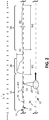
- FIG. 2 is a cross-sectional view of an enlarged surface of workpiece 12 along line 2-2 of FIG. 1 .
- the depiction in FIG. 2 is not drawn to scale, although some of the sizes of the features therein will be specified below.
- nominal line 29 represents the shape of the local region of the design for the part that workpiece 12 will become.
- Nominal line 29 serves as a reference from which defect detection system 10 measures workpiece 12.
- Pathway 30 is offset from nominal line 29, away from workpiece 12, and is the path that probe 24 follows as dovetail slot 14 is measured.
- controller 15 shown in FIG. 1 ).
- the amount of movement required to keep tip 26 in contact with e.g., for a tactile tip 26 or a specified distance away from the surface (e.g., for an optical or laser tip 26) can be measured, or the changing force (e.g., from a force-loaded tactile probe 24) or changing light signal (e.g., for an optical or laser tip 26) can be measured.
- tip 26 can be moved along workpiece 12 at a relatively constant rate, and measurements can be taken at either time or displacement increments. This results in a data set with data points that geometrically separated by interval I.
- defect 28 is what defect detection system 10 is configured to find, measure, and analyze.
- defect 28 is a micro-level feature that has depth D 1 on the order of 3.8 ⁇ m (0.00015 in.) and width W 1 on the order of 7.6 ⁇ m (0.00030 in.).
- Defect 28 has the potential to evolve into a crack during service, which can trigger replacement of the entire part.
- surface roughness 32 is a high frequency, nano-level feature with depth D 2 and width W 2 being an order of magnitude smaller than defect 28.
- deviation 34 is a macro-level feature that indicates a general straying from the nominal shape that workpiece 12 should have. More specifically, a deviation 34 has a ratio of D 2 /W 2 that is approximately ten times smaller than the ratio of D 1 /W 1 that a defect 28 would have. Accordingly, deviation 34 is at least one order of magnitude larger than defect 28. While surface roughness 32 and deviation 34 may cause issues on their own, they are not typically involved with the type of crack formation that defect 28 is.
- tip 26 is configured to have a resolution of 2.5 ⁇ m (0.00010 in.) or smaller in depth and 5.1 ⁇ m (0.00020 in.) or smaller in width. Therefore, the components and configuration of defect detection system 10 allow for the workpiece 12 to be analyzed at a micro-level because defect detection system 10 can locate and measure micro-level features like defect 28.
- FIG. 3 is a flowchart of method 48 of inspecting workpiece 12 for defects 28 (shown in FIG. 2 ).
- workpiece 12 is positioned to align a first dovetail slot 14 with defect detection system 10.
- defect detection system 10 passes tip around pathway 30 to measure workpiece 12 at 20% height of dovetail slot 14, recording data points at intervals I.
- defect detection system 10 passes tip around pathway 30 to measure workpiece 12 at 50% height of dovetail slot 14, recording data points at intervals I that represent the local distance and orientation of workpiece 12 with respect to pathway 30.
- defect detection system 10 passes tip around pathway 30 to measure workpiece 12 at 80% height of dovetail slot 14, recording data points at intervals I.
- step 56 method 48 moves to a sub-method 57 of evaluation.
- Sub-method 57 includes steps 58 and 60 and will be discussed in greater detail with respect to FIG. 4 .
- step 58 the data points are analyzed.
- step 60 a binary decision is made as to whether the first dovetail slot 14 is acceptable by comparing defect 28 against predetermined size criteria threshold. For example, if defect 28 has a depth D 1 greater than or equal to 3.8 ⁇ m (0.00015 in.) and/or a width W 1 greater than or equal to 7.6 ⁇ m (0.00030 in.), then the first dovetail slot 14 is not acceptable. In that situation, then method 48 is halted and workpiece 12 can be scrapped at step 62.
- first dovetail slot 14 is acceptable (i.e., there are no defects 28 or any defect 28 that is present is sufficiently small)
- workpiece 12 is repositioned to align a second dovetail slot 14 with defect detection system 10 at step 64. From there, method 48 is continued and steps 52-60 and 64 are repeated until all of the dovetail slots 14 are measured, analyzed, and deemed acceptable.
- FIG. 4 is a flowchart of sub-method 57 of detecting, measuring, and evaluating any defects 28 that may be present in workpiece 12.
- a raw curve is constructed by listing all of the data points from the three passes together.
- a short meanline curve is constructed by generating a moving average of, for example, 10-20 adjacent data points.
- a filtered curve is constructed by finding the difference between the short meanline curve and the raw curve.
- step 74 is a high-pass filter that eliminates the low-frequency deviations 34 from the analysis of workpiece 12 but leaves the medium-frequency defects 28 (if there are any) and the high-frequency surface roughness 32.
- the minimum value and the maximum values of the filtered curve are found and are evaluated.
- the difference between the maximum and the minimum values is calculated and compared to a threshold value. If the difference exceeds the threshold value, then the first dovetail slot 14 is unacceptable, and step 62 of method 48 can be executed. If the difference is smaller than the threshold value, then the first dovetail slot 14 is acceptable, and step 64 of method 48 can be executed.
- the maximum and minimum values are calculated and separately compared to a maximum and a minimum threshold value, respectively.
- a cleaned meanline curve is constructed by running the short meanline curve through a low-pass filter. Thereby, step 77 eliminates any remaining high-frequency surface roughness 32 from the analysis of workpiece 12 but leaves the medium-frequency defects 28 (if there are any).
- the second derivative of the cleaned meanline curve is computed in order to construct a reversal curve.
- the reversal curve is analyzed to find "reversals" which are locations where the reversal curve crosses "0" (i.e., where the sign changes between positive and negative). These locations represent reversals of the radius of curvature from one side of the surface to the other.
- the distances between pairs of adjacent reversals are calculated. These distances represent the size of width W 1 of each defect 28.
- a long meanline curve is constructed by generating a moving average of, for example, 100-200 adjacent data points.
- a depth curve is constructed by subtracting the long meanline curve from the first curve (of step 70), wherein the depth curve represents the depth D 1 of each defect 28.
- the calculated width W 1 and depth D 1 are compared to threshold values. If at least one of the values are too large, then then the first dovetail slot 14 is unacceptable, and step 62 of method 48 can be executed. If both values are sufficiently small, then the first dovetail slot 14 is acceptable, and step 64 of method 48 can be executed.
- Employing sub-method 57 can provide an analysis of micro-level features without interference from macro-level or nano-level features.
- FIG. 5 is a flowchart of an alternate embodiment sub-method 88 of evaluating any defects 28 that may be present in workpiece 12. This method can be employed, for example, in step 87 of sub-method 57 to determine whether the first dovetail slot 14 is acceptable.
- a ternary decision is made as to the acceptability of the first dovetail slot 14.
- the three answers are "acceptable”, “unacceptable”, and “investigate further”. If the answer is "unacceptable”, then the next step would be step 62 of method 48, but if the answer is "acceptable”, then the next step would be either step 78 of sub-method 57 or step 64 of method 48.
- dovetail slot 14 would require further investigation. If defect 28 were smaller than these ranges, then the first dovetail slot 14 would be acceptable, and step 64 of method 48 would be next. But if defect 28 were larger than these ranges, then the first dovetail slot 14 would be unacceptable, and step 62 of method 48 would be next.
- sub-method 88 can be employed in step 76 of sub-method 57.
- defect detection system 10 can alter its parameters from the initial pass, for example, by decreasing interval I at which data is collected, by traveling in the reverse direction from the initial pass and/or by changing another parameter that can decrease the hysteresis in tip 26 (e.g., changing the force on tip 26 or changing the spectrum of light gathered by tip 26).
- defect 28 can be judged in a binary decision at step 94 to determine the acceptability of dovetail slot 14. For example, if defect 28 has a depth D 1 greater than or equal to 3.8 ⁇ m (0.00015 in.) and/or a width W 1 greater than or equal to 7.6 ⁇ m (0.00030 in.), then dovetail slot 14 is not acceptable.
- alternative forms of data analysis can be performed during sub-method 88, for example, Fourier analysis. Employing sub-method 88 can provide a rapid initial pass that saves time while providing greater measurement accuracy for any areas that are questionable.
Landscapes
- Physics & Mathematics (AREA)
- Engineering & Computer Science (AREA)
- General Physics & Mathematics (AREA)
- Theoretical Computer Science (AREA)
- Mathematical Physics (AREA)
- Mathematical Analysis (AREA)
- Pure & Applied Mathematics (AREA)
- Computational Mathematics (AREA)
- Data Mining & Analysis (AREA)
- Mathematical Optimization (AREA)
- Computer Vision & Pattern Recognition (AREA)
- Life Sciences & Earth Sciences (AREA)
- General Engineering & Computer Science (AREA)
- Quality & Reliability (AREA)
- Operations Research (AREA)
- Probability & Statistics with Applications (AREA)
- Software Systems (AREA)
- Algebra (AREA)
- Databases & Information Systems (AREA)
- Health & Medical Sciences (AREA)
- Chemical & Material Sciences (AREA)
- Analytical Chemistry (AREA)
- Biochemistry (AREA)
- General Health & Medical Sciences (AREA)
- Immunology (AREA)
- Pathology (AREA)
- Bioinformatics & Cheminformatics (AREA)
- Bioinformatics & Computational Biology (AREA)
- Evolutionary Biology (AREA)
- Length Measuring Devices By Optical Means (AREA)
- Length Measuring Devices With Unspecified Measuring Means (AREA)
Abstract
Description
- Manufactured components for machinery are traditionally inspected in order to ensure that they are made substantially in accordance with their nominal specifications. Any differences can be due to imprecisions in manufacturing techniques such as worn cutting tools, fixture movement, thermal growth or shrinkage, among other things. A part may have several different specifications to ensure proper fitment, wear-in, longevity, etc. Therefore, a workpiece that becomes the part can be measured in different ways for these and other properties at various stages of manufacturing. For example, the workpiece can be measured using dimensional metrology to make sure that the macro-level features are the correct shape and size, and the workpiece can also be measured using non-destructive evaluation to make sure that the nano-level surface finish is appropriate.
- Due to the accuracy and precision desired for inspection, different equipment and techniques can be used to measure macro-level features than are used to measure nano-level features. Furthermore, there can be micro-level features that are difficult to differentiate from the macro-level and/or nano-level features. Such micro-level features can include defects which can be important to identify as they can affect the suitability and/or the life-span of the part.
- The following are non-exclusive descriptions of possible embodiments of the present invention.
- A method of evaluating an article, according to an exemplary embodiment of this disclosure, among other possible things includes: measuring a first feature of the article using a defect detection device; recording a set of data points representing the first feature; analyzing the set of data points, the analyzing comprising: constructing a filtered curve by constructing a raw curve by listing the set of data points, constructing a first meanline curve, and finding a first difference between the raw curve and the first meanline curve; constructing a reversal curve by calculating a second derivative of a meanline curve constructed from the set of data points; and deciding an acceptability of the first feature of the article.
- The method of the preceding paragraph can optionally include, additionally and/or alternatively, any one or more of the following steps, features, configurations and/or additional components:
A further embodiment of the foregoing method, wherein constructing the reversal curve comprises: constructing the first meanline curve by generating a moving average of at least 10 data points. - A further embodiment of any of the foregoing methods, wherein constructing the filtered curve eliminates deviations of the article from a design of the article from the step of analyzing of the set of data points.
- A further embodiment of any of the foregoing methods, wherein constructing the reversal curve further comprises: calculating a maximum value and a minimum value from the filtered curve.
- A further embodiment of any of the foregoing methods, wherein deciding the acceptability of the first feature comprises: finding a maximum value of the filtered curve; and finding a minimum value of the filtered curve.
- A further embodiment of any of the foregoing methods, wherein deciding the acceptability of the first feature further comprises: calculating a second difference between the maximum value and the minimum value of the filtered curve.
- A further embodiment of any of the foregoing methods, wherein constructing the reversal curve further comprises: computing the second derivative of the first meanline curve.
- A further embodiment of any of the foregoing methods, wherein analyzing the set of data points comprises: analyzing the reversal curve to find reversals of a radius of curvature of a surface of the article.
- A further embodiment of any of the foregoing methods, wherein analyzing the set of data points comprises: calculating a distance between a pair of adjacent reversals; and comparing the distance to a predetermined criteria threshold.
- A further embodiment of any of the foregoing methods, wherein measuring the first feature comprises: passing the probe across a first region of the first feature; passing the probe across a second region of the first feature; and passing the probe across a third region of the first feature.
- A further embodiment of any of the foregoing methods, wherein constructing a reversal curve comprises: constructing a second meanline curve by generating a moving average of at least 100 data points; and finding a difference between the second meanline curve and the raw curve to construct a depth curve.
- A further embodiment of any of the foregoing methods, wherein the method further comprises: aligning the defect detection device with the first feature prior to measuring the first feature; and aligning the defect detection device with a second feature after the first feature has been decided to be acceptable.
- A further embodiment of any of the foregoing methods, wherein the method further comprises: halting measuring the article after the first feature has been decided to be unacceptable.
- A further embodiment of any of the foregoing methods, wherein deciding an acceptability of the first feature of the article requires additional investigation, the method further comprising: remeasuring an area of the first feature using a different set of measurement parameters; recording another set of data points representing the first feature; analyzing the another set of data points; and deciding whether the first feature of the article is acceptable or unacceptable.
- A further embodiment of any of the foregoing methods, wherein the different set of measurement parameters used in remeasuring are different than the step of measuring in that: an interval between data points in decreased; a direction is reversed; a force of the defect detection device is different; or a light of the defect detection device is different.
- A further embodiment of any of the foregoing methods, wherein the defect detection device measures the first feature of the article by contacting the article.
- A further embodiment of any of the foregoing methods, wherein the defect detection device contacts the article by a stylus or a plurality of photons.
- A method of measuring a defect in a rotor disk, according to an exemplary embodiment of this disclosure, among other possible things includes: passing a probe around a dovetail slot of the rotor disk; analyzing a set of data points gathered by the passing of the probe, the analyzing comprising: constructing a filtered curve by constructing a raw curve by listing the set of data points, constructing a meanline curve, and finding the difference between the raw curve and the meanline curve to calculate a filtered curve; and constructing a reversal curve by calculating a second derivative of a meanline curve; and deciding whether the dovetail slot is acceptable or unacceptable.
- The method of the preceding paragraph can optionally include, additionally and/or alternatively, any one or more of the following steps, features, configurations and/or additional components:
A further embodiment of the foregoing method, wherein the probe comprises a stylus, an optical system, or a laser system. - A further embodiment of any of the foregoing methods, wherein analyzing the set of data points further comprises: calculating a maximum value and a minimum value from the filtered curve.
- Any of the foregoing methods may be performed automatically using a computer.
- A further embodiment of any of the foregoing methods may further comprise the step of accepting or rejecting the article based on the acceptability.
-
-
FIG. 1 is a perspective view of a defect detection system and a workpiece. -
FIG. 2 is a cross-sectional view of an enlarged surface of the workpiece along line 2-2 inFIG. 1 . -
FIG. 3 is a flowchart of a method of inspecting the workpiece for defects. -
FIG. 4 is a flowchart of a sub-method of detecting, measuring, and evaluating any defects that may be present. -
FIG. 5 is a flowchart of an alternate embodiment sub-method of evaluating any defects that may be present. -
FIG. 1 is a perspective view ofdefect detection system 10 andworkpiece 12. In the illustrated embodiment,workpiece 12 is an article that is in the manufacturing process, for example, to become a rotor disk (not shown).Workpiece 12 includes a plurality of circumferentially spaced dovetail slots 14 (although only one is visible inFIG. 1 ) that are each configured to receive a rotor blade (not shown).Defect detection system 10 comprisescontroller 15,base 16,X-table 18, Y-table 20, rotary table 22,probe 24, andtip 26.Controller 15 controls the movements ofdefect detection system 10 and records and analyzes measurements therefrom.Base 16 is configured to be movable parallel to the Z-axis with respect toworkpiece 12.X-table 18 is slidably connected tobase 16 and can move parallel to the X-axis. Y-table 20 is slidably connected toX-table 18 and can move parallel to the Y-axis. Rotary table 22 is rotatably connected to Y-table 20 and can rotate in the XY plane, parallel to the Z-axis. In alternate embodiments, other configurations ofdefect detection system 10 are possible that provide the required degrees of freedom for the measurement ofworkpiece 12. -
Probe 24 is connected to rotary table 22 and includestip 26 for measuringdovetail slots 14.Probe 24 can be a pointed stylus that contactsworkpiece 12 orprobe 24 can be an optical (e.g., confocal) or laser system that measures photons that are reflected off of workpiece 12 (that can be sent bytip 26 or are present in the ambient environment). In order to measuredovetail slot 14,defect detection system 10 movestip 26 in the X and Y directions along the inside ofdovetail slot 14 at a constant Z position. In addition,probe 24 is rotated so thattip 26 remains normal to the local surface ofdovetail slot 14 that is being measured at any given time. In one embodiment, a full measurement ofdovetail slot 14 includes three parallel passes along different regions of dovetail slot 14 - one at 20% height, one at 50% height (as denoted by the phantom line), and one at 80% height. In this manner, a surface feature, such asdefect 28, can be detected even if it does not extend fully from 0% height to 100% height. - In order to better illustrate the surface features that can be encountered by
defect detection system 10,FIG. 2 is a cross-sectional view of an enlarged surface ofworkpiece 12 along line 2-2 ofFIG. 1 . The depiction inFIG. 2 is not drawn to scale, although some of the sizes of the features therein will be specified below. - In the illustrated embodiment,
nominal line 29 represents the shape of the local region of the design for the part thatworkpiece 12 will become.Nominal line 29 serves as a reference from whichdefect detection system 10 measuresworkpiece 12. Pathway 30 is offset fromnominal line 29, away fromworkpiece 12, and is the path thatprobe 24 follows asdovetail slot 14 is measured. Astip 26 is moved along the surface of workpiece 12 (as depicted inFIG. 2 , in the direction of right to left), there are multiple properties can be measured by controller 15 (shown inFIG. 1 ). For example, the amount of movement required to keeptip 26 in contact with (e.g., for a tactile tip 26) or a specified distance away from the surface (e.g., for an optical or laser tip 26) can be measured, or the changing force (e.g., from a force-loaded tactile probe 24) or changing light signal (e.g., for an optical or laser tip 26) can be measured. During inspection,tip 26 can be moved alongworkpiece 12 at a relatively constant rate, and measurements can be taken at either time or displacement increments. This results in a data set with data points that geometrically separated by interval I. - Shown in
FIG. 2 , on the surface ofworkpiece 12, are three types of features that can be encountered by probe 24:defect 28,surface roughness 32, anddeviation 34.Defect 28 is whatdefect detection system 10 is configured to find, measure, and analyze. In the illustrated embodiment,defect 28 is a micro-level feature that has depth D1 on the order of 3.8 µm (0.00015 in.) and width W1 on the order of 7.6 µm (0.00030 in.).Defect 28 has the potential to evolve into a crack during service, which can trigger replacement of the entire part. - In contrast,
surface roughness 32 is a high frequency, nano-level feature with depth D2 and width W2 being an order of magnitude smaller thandefect 28. Also in contrast,deviation 34 is a macro-level feature that indicates a general straying from the nominal shape that workpiece 12 should have. More specifically, adeviation 34 has a ratio of D2/W2 that is approximately ten times smaller than the ratio of D1/W1 that adefect 28 would have. Accordingly,deviation 34 is at least one order of magnitude larger thandefect 28. Whilesurface roughness 32 anddeviation 34 may cause issues on their own, they are not typically involved with the type of crack formation thatdefect 28 is. - Given the general size of
defect 28,tip 26 is configured to have a resolution of 2.5 µm (0.00010 in.) or smaller in depth and 5.1 µm (0.00020 in.) or smaller in width. Therefore, the components and configuration ofdefect detection system 10 allow for theworkpiece 12 to be analyzed at a micro-level becausedefect detection system 10 can locate and measure micro-level features likedefect 28. -
FIG. 3 is a flowchart ofmethod 48 of inspectingworkpiece 12 for defects 28 (shown inFIG. 2 ). Atstep 50,workpiece 12 is positioned to align afirst dovetail slot 14 withdefect detection system 10. Atstep 52,defect detection system 10 passes tip aroundpathway 30 to measureworkpiece 12 at 20% height ofdovetail slot 14, recording data points at intervals I. Atstep 54,defect detection system 10 passes tip aroundpathway 30 to measureworkpiece 12 at 50% height ofdovetail slot 14, recording data points at intervals I that represent the local distance and orientation ofworkpiece 12 with respect topathway 30. Atstep 56,defect detection system 10 passes tip aroundpathway 30 to measureworkpiece 12 at 80% height ofdovetail slot 14, recording data points at intervals I. - After
step 56,method 48 moves to a sub-method 57 of evaluation. Sub-method 57 includessteps FIG. 4 . Atstep 58, the data points are analyzed. Atstep 60, a binary decision is made as to whether thefirst dovetail slot 14 is acceptable by comparingdefect 28 against predetermined size criteria threshold. For example, ifdefect 28 has a depth D1 greater than or equal to 3.8 µm (0.00015 in.) and/or a width W1 greater than or equal to 7.6 µm (0.00030 in.), then thefirst dovetail slot 14 is not acceptable. In that situation, thenmethod 48 is halted andworkpiece 12 can be scrapped atstep 62. If thefirst dovetail slot 14 is acceptable (i.e., there are nodefects 28 or anydefect 28 that is present is sufficiently small), then workpiece 12 is repositioned to align asecond dovetail slot 14 withdefect detection system 10 atstep 64. From there,method 48 is continued and steps 52-60 and 64 are repeated until all of thedovetail slots 14 are measured, analyzed, and deemed acceptable. -
FIG. 4 is a flowchart ofsub-method 57 of detecting, measuring, and evaluating anydefects 28 that may be present inworkpiece 12. In the illustrated embodiment, atstep 70, a raw curve is constructed by listing all of the data points from the three passes together. Atstep 72, a short meanline curve is constructed by generating a moving average of, for example, 10-20 adjacent data points. Atstep 74, a filtered curve is constructed by finding the difference between the short meanline curve and the raw curve. Thereby, step 74 is a high-pass filter that eliminates the low-frequency deviations 34 from the analysis ofworkpiece 12 but leaves the medium-frequency defects 28 (if there are any) and the high-frequency surface roughness 32. Atstep 76, the minimum value and the maximum values of the filtered curve are found and are evaluated. In one embodiment, the difference between the maximum and the minimum values is calculated and compared to a threshold value. If the difference exceeds the threshold value, then thefirst dovetail slot 14 is unacceptable, and step 62 ofmethod 48 can be executed. If the difference is smaller than the threshold value, then thefirst dovetail slot 14 is acceptable, and step 64 ofmethod 48 can be executed. In an alternate embodiment, the maximum and minimum values are calculated and separately compared to a maximum and a minimum threshold value, respectively. - At
step 77, if it would be advantageous, a cleaned meanline curve is constructed by running the short meanline curve through a low-pass filter. Thereby, step 77 eliminates any remaining high-frequency surface roughness 32 from the analysis ofworkpiece 12 but leaves the medium-frequency defects 28 (if there are any). Atstep 78, the second derivative of the cleaned meanline curve is computed in order to construct a reversal curve. Atstep 80, the reversal curve is analyzed to find "reversals" which are locations where the reversal curve crosses "0" (i.e., where the sign changes between positive and negative). These locations represent reversals of the radius of curvature from one side of the surface to the other. Atstep 82, the distances between pairs of adjacent reversals are calculated. These distances represent the size of width W1 of eachdefect 28. - At
step 84, a long meanline curve is constructed by generating a moving average of, for example, 100-200 adjacent data points. Atstep 86, a depth curve is constructed by subtracting the long meanline curve from the first curve (of step 70), wherein the depth curve represents the depth D1 of eachdefect 28. Atstep 87, the calculated width W1 and depth D1 are compared to threshold values. If at least one of the values are too large, then then thefirst dovetail slot 14 is unacceptable, and step 62 ofmethod 48 can be executed. If both values are sufficiently small, then thefirst dovetail slot 14 is acceptable, and step 64 ofmethod 48 can be executed. Employingsub-method 57 can provide an analysis of micro-level features without interference from macro-level or nano-level features. -
FIG. 5 is a flowchart of an alternate embodiment sub-method 88 of evaluating anydefects 28 that may be present inworkpiece 12. This method can be employed, for example, instep 87 ofsub-method 57 to determine whether thefirst dovetail slot 14 is acceptable. - In the illustrated embodiment, at
step 90, a ternary decision is made as to the acceptability of thefirst dovetail slot 14. In such an embodiment, the three answers are "acceptable", "unacceptable", and "investigate further". If the answer is "unacceptable", then the next step would be step 62 ofmethod 48, but if the answer is "acceptable", then the next step would be either step 78 ofsub-method 57 or step 64 ofmethod 48. Alternatively, for example, ifdefect 28 has a depth D1 between 2.5 µm (0.00010 in.) and 5.1 µm (0.00020 in.) and/or a width W1 between 5.1 µm (0.00020 in.) and 6.4 µm (0.00025 in.) and 8.9 µm (0.00035 in.),dovetail slot 14 would require further investigation. Ifdefect 28 were smaller than these ranges, then thefirst dovetail slot 14 would be acceptable, and step 64 ofmethod 48 would be next. But ifdefect 28 were larger than these ranges, then thefirst dovetail slot 14 would be unacceptable, and step 62 ofmethod 48 would be next. In an alternate embodiment, sub-method 88 can be employed instep 76 ofsub-method 57. In such an embodiment, if the first dovetail slot 44 were acceptable, then step 78 would be next.
Given a result of "investigate further" atstep 90, atstep 92,tip 26 is returned only to the area to be investigated in order to measure thedefect 28 in question again. To complete the investigation,defect detection system 10 can alter its parameters from the initial pass, for example, by decreasing interval I at which data is collected, by traveling in the reverse direction from the initial pass and/or by changing another parameter that can decrease the hysteresis in tip 26 (e.g., changing the force ontip 26 or changing the spectrum of light gathered by tip 26). Once a more accurate remeasurement ofdefect 28 is obtained,defect 28 can be judged in a binary decision atstep 94 to determine the acceptability ofdovetail slot 14. For example, ifdefect 28 has a depth D1 greater than or equal to 3.8 µm (0.00015 in.) and/or a width W1 greater than or equal to 7.6 µm (0.00030 in.), then dovetailslot 14 is not acceptable. In addition, alternative forms of data analysis can be performed duringsub-method 88, for example, Fourier analysis. Employingsub-method 88 can provide a rapid initial pass that saves time while providing greater measurement accuracy for any areas that are questionable. - While the invention has been described with reference to an exemplary embodiment(s), it will be understood by those skilled in the art that various changes may be made and equivalents may be substituted for elements thereof without departing from the scope of the invention. In addition, many modifications may be made to adapt a particular situation or material to the teachings of the invention without departing from the essential scope thereof. Therefore, it is intended that the invention not be limited to the particular embodiment(s) disclosed, but that the invention will include all embodiments falling within the scope of the appended claims.
Claims (15)
- A method of evaluating an article (12), the method comprising:measuring a first feature of the article (12) using a defect detection device (10);recording a set of data points representing the first feature;analyzing the set of data points, the analyzing comprising:constructing a filtered curve by constructing a raw curve by listing the set of data points, constructing a first meanline curve, and finding a first difference between the raw curve and the first meanline curve;constructing a reversal curve by calculating a second derivative of a meanline curve constructed from the set of data points; anddeciding an acceptability of the first feature of the article (12).
- The method of claim 1, wherein constructing the reversal curve comprises constructing the first meanline curve by generating a moving average of at least 10 data points.
- The method of claim 1 or 2, wherein constructing the filtered curve eliminates deviations of the article (12) from a design of the article (12) from the step of analyzing of the set of data points.
- The method of any preceding claim, wherein constructing the reversal curve further comprises calculating a maximum value and a minimum value from the filtered curve, optionally wherein deciding the acceptability of the first feature comprises:finding a maximum value of the filtered curve; andfinding a minimum value of the filtered curve, further optionally wherein:deciding the acceptability of the first feature further comprises calculating a second difference between the maximum value and the minimum value of the filtered curve; and/orwherein constructing the reversal curve further comprises computing the second derivative of the first meanline curve.
- The method of any preceding claim, wherein analyzing the set of data points comprises analyzing the reversal curve to find reversals of a radius of curvature of a surface of the article, optionally wherein analyzing the set of data points comprises:calculating a distance between a pair of adjacent reversals; andcomparing the distance to a predetermined criteria threshold.
- The method of any preceding claim, wherein measuring the first feature comprises:passing a probe (26) across a first region of the first feature;passing the probe (26) across a second region of the first feature; andpassing the probe (26) across a third region of the first feature.
- The method of any preceding claim, wherein constructing a reversal curve comprises:constructing a second meanline curve by generating a moving average of at least 100 data points; andfinding a difference between the second meanline curve and the raw curve to construct a depth curve.
- The method of any preceding claim, further comprising:aligning the defect detection device (10) with the first feature prior to measuring the first feature; andaligning the defect detection device (10) with a second feature after the first feature has been decided to be acceptable.
- The method of any preceding claim, further comprising halting measuring the article (12) after the first feature has been decided to be unacceptable.
- The method of any preceding claim, wherein the step of deciding an acceptability of the first feature of the article (12) comprises deciding the first feature requires additional investigation, and the method further comprises:remeasuring an area of the first feature using a different set of measurement parameters;recording another set of data points representing the first feature;analyzing the another set of data points; anddeciding whether the first feature of the article (12) is acceptable or unacceptable.
- The method of claim 10, wherein the different set of measurement parameters used in remeasuring are different than the step of measuring in that:an interval between data points in decreased;a direction is reversed;a force of the defect detection device (10) is different; ora light of the defect detection device (10) is different.
- The method of any preceding claim, wherein the defect detection device (10) measures the first feature of the article (12) by contacting the article (12), optionally wherein the defect detection device (10) contacts the article (12) by a stylus (24) or a plurality of photons.
- A method of measuring a defect in a rotor disk (12), the method comprising:passing a probe (24) around a dovetail slot (14) of the rotor disk (12);analyzing a set of data points gathered by the passing of the probe (24), the analyzing comprising:constructing a filtered curve by constructing a raw curve by listing the set of data points, constructing a meanline curve, and finding the difference between the raw curve and the meanline curve to calculate a filtered curve; andconstructing a reversal curve by calculating a second derivative of a meanline curve; anddeciding whether the dovetail slot (14) is acceptable or unacceptable.
- The method of claim 13, wherein the probe (24) comprises a stylus, an optical system, or a laser system.
- The method of claim 13 or 14, wherein analyzing the set of data points further comprises calculating a maximum value and a minimum value from the filtered curve.
Applications Claiming Priority (1)
| Application Number | Priority Date | Filing Date | Title |
|---|---|---|---|
| US15/794,393 US10878554B2 (en) | 2017-10-26 | 2017-10-26 | Defect detection and measurement method |
Publications (2)
| Publication Number | Publication Date |
|---|---|
| EP3477244A1 true EP3477244A1 (en) | 2019-05-01 |
| EP3477244B1 EP3477244B1 (en) | 2022-10-12 |
Family
ID=64051433
Family Applications (1)
| Application Number | Title | Priority Date | Filing Date |
|---|---|---|---|
| EP18202918.1A Active EP3477244B1 (en) | 2017-10-26 | 2018-10-26 | Defect detection and measurement method |
Country Status (2)
| Country | Link |
|---|---|
| US (1) | US10878554B2 (en) |
| EP (1) | EP3477244B1 (en) |
Families Citing this family (2)
| Publication number | Priority date | Publication date | Assignee | Title |
|---|---|---|---|---|
| JP7827478B2 (en) * | 2022-02-24 | 2026-03-10 | 株式会社神戸製鋼所 | Workpiece measurement method, workpiece measurement system, and program |
| US20240273706A1 (en) * | 2023-02-10 | 2024-08-15 | Rtx Corporation | Inspecting parts using geometric models |
Citations (3)
| Publication number | Priority date | Publication date | Assignee | Title |
|---|---|---|---|---|
| US20080024778A1 (en) * | 2003-10-17 | 2008-01-31 | Astellas Pharma Inc. | Different-Kind-of-Object Detector Employing Plane Spectrometer |
| WO2013015013A1 (en) * | 2011-07-27 | 2013-01-31 | 株式会社日立製作所 | Appearance inspection method and apparatus therefor |
| US20170227356A1 (en) * | 2014-08-08 | 2017-08-10 | Nippon Steel & Sumitomo Metal Corporation | Line displacement evaluation method, line displacement evaluation device, program, and recording medium |
Family Cites Families (12)
| Publication number | Priority date | Publication date | Assignee | Title |
|---|---|---|---|---|
| US5345514A (en) | 1991-09-16 | 1994-09-06 | General Electric Company | Method for inspecting components having complex geometric shapes |
| US5371462A (en) | 1993-03-19 | 1994-12-06 | General Electric Company | Eddy current inspection method employing a probe array with test and reference data acquisition and signal processing |
| US5781007A (en) | 1995-10-24 | 1998-07-14 | General Electric Company | Portable three axis scanner to inspect a gas turbine engine spool by eddy current or ultrasonic inspection |
| US6608478B1 (en) | 2001-12-07 | 2003-08-19 | General Electric Company | Rotor slot bottom inspection apparatus and method |
| US6972561B2 (en) | 2003-02-28 | 2005-12-06 | General Electric Company | Internal eddy current inspection |
| US7019537B2 (en) | 2003-05-16 | 2006-03-28 | General Electric Company | Non-destructive determination of machining induced surface defects on metal parts |
| US7174788B2 (en) | 2003-12-15 | 2007-02-13 | General Electric Company | Methods and apparatus for rotary machinery inspection |
| US7190162B2 (en) | 2004-07-23 | 2007-03-13 | General Electric Company | Methods and apparatus for inspecting a component |
| US20110184694A1 (en) * | 2007-08-19 | 2011-07-28 | Camtek Ltd. | Depth measurements of narrow holes |
| US9689655B2 (en) * | 2008-10-29 | 2017-06-27 | Renishaw Plc | Measurement method |
| US8493064B2 (en) | 2010-08-24 | 2013-07-23 | United Western Technologies Corporation | Apparatus, system, and method for maintaining normalcy of a sensor with respect to a structure |
| US9470508B2 (en) * | 2014-04-23 | 2016-10-18 | General Electric Company | Non-contact coordinate measuring system |
-
2017
- 2017-10-26 US US15/794,393 patent/US10878554B2/en active Active
-
2018
- 2018-10-26 EP EP18202918.1A patent/EP3477244B1/en active Active
Patent Citations (3)
| Publication number | Priority date | Publication date | Assignee | Title |
|---|---|---|---|---|
| US20080024778A1 (en) * | 2003-10-17 | 2008-01-31 | Astellas Pharma Inc. | Different-Kind-of-Object Detector Employing Plane Spectrometer |
| WO2013015013A1 (en) * | 2011-07-27 | 2013-01-31 | 株式会社日立製作所 | Appearance inspection method and apparatus therefor |
| US20170227356A1 (en) * | 2014-08-08 | 2017-08-10 | Nippon Steel & Sumitomo Metal Corporation | Line displacement evaluation method, line displacement evaluation device, program, and recording medium |
Also Published As
| Publication number | Publication date |
|---|---|
| US10878554B2 (en) | 2020-12-29 |
| EP3477244B1 (en) | 2022-10-12 |
| US20190130557A1 (en) | 2019-05-02 |
Similar Documents
| Publication | Publication Date | Title |
|---|---|---|
| CN102892552B (en) | By interfering method and apparatus object thickness being carried out to optical measurement | |
| KR101021320B1 (en) | Systems and Methods for Process Deviation Monitoring | |
| JP7172951B2 (en) | Semiconductor wafer evaluation method, semiconductor wafer sorting method, and device manufacturing method | |
| US10166644B2 (en) | Processing inspection workpiece for machine tool, and on-machine measurement method using said workpiece | |
| US20050100205A1 (en) | Method for measuring three dimensional shape of a fine pattern | |
| US6985238B2 (en) | Non-contact measurement system for large airfoils | |
| CN108801164B (en) | Method and system for testing gap value of workpiece based on laser | |
| EP2851650B1 (en) | Tire shape inspection method and tire shape inspection device | |
| EP3477244B1 (en) | Defect detection and measurement method | |
| CN108766901A (en) | The method for detecting wafer work platform flatness | |
| JP2005331515A (en) | Nondestructive evaluation of subsurface damage in optical elements. | |
| EP2494306B1 (en) | Device and method for the characterization of the surface of an aspheric diffractive structure | |
| US6191857B1 (en) | Measuring method and apparatus | |
| JP7112883B2 (en) | Worm gear inspection method | |
| WO2015098349A1 (en) | Pattern measurement device and computer program | |
| JPH04232407A (en) | Inspecting method of tool | |
| CN119043412A (en) | Generator panel cutting quality detection method and system | |
| US7433047B1 (en) | Runout characterization | |
| Ali | The influence of strategic parameters on roundness accuracy development | |
| JP4160593B2 (en) | Defect detection method and defect inspection apparatus | |
| Bennett et al. | Surface measurement and characterization | |
| JPH0372204A (en) | Checking method of outer appearance of soldering part | |
| KR20260030745A (en) | How to determine the edge radius of a cutting tool | |
| Pelc | Analysis of influence of the shape of cutting insert on change of the parameter value describing the deviation of the profile of surface roughness | |
| Pelc et al. | The effect of measurement method for assessing stereometric structure of surface |
Legal Events
| Date | Code | Title | Description |
|---|---|---|---|
| PUAI | Public reference made under article 153(3) epc to a published international application that has entered the european phase |
Free format text: ORIGINAL CODE: 0009012 |
|
| STAA | Information on the status of an ep patent application or granted ep patent |
Free format text: STATUS: THE APPLICATION HAS BEEN PUBLISHED |
|
| AK | Designated contracting states |
Kind code of ref document: A1 Designated state(s): AL AT BE BG CH CY CZ DE DK EE ES FI FR GB GR HR HU IE IS IT LI LT LU LV MC MK MT NL NO PL PT RO RS SE SI SK SM TR |
|
| AX | Request for extension of the european patent |
Extension state: BA ME |
|
| STAA | Information on the status of an ep patent application or granted ep patent |
Free format text: STATUS: REQUEST FOR EXAMINATION WAS MADE |
|
| 17P | Request for examination filed |
Effective date: 20191101 |
|
| RBV | Designated contracting states (corrected) |
Designated state(s): AL AT BE BG CH CY CZ DE DK EE ES FI FR GB GR HR HU IE IS IT LI LT LU LV MC MK MT NL NO PL PT RO RS SE SI SK SM TR |
|
| RAP1 | Party data changed (applicant data changed or rights of an application transferred) |
Owner name: RAYTHEON TECHNOLOGIES CORPORATION |
|
| STAA | Information on the status of an ep patent application or granted ep patent |
Free format text: STATUS: EXAMINATION IS IN PROGRESS |
|
| 17Q | First examination report despatched |
Effective date: 20210526 |
|
| GRAP | Despatch of communication of intention to grant a patent |
Free format text: ORIGINAL CODE: EPIDOSNIGR1 |
|
| STAA | Information on the status of an ep patent application or granted ep patent |
Free format text: STATUS: GRANT OF PATENT IS INTENDED |
|
| INTG | Intention to grant announced |
Effective date: 20220425 |
|
| GRAS | Grant fee paid |
Free format text: ORIGINAL CODE: EPIDOSNIGR3 |
|
| GRAA | (expected) grant |
Free format text: ORIGINAL CODE: 0009210 |
|
| STAA | Information on the status of an ep patent application or granted ep patent |
Free format text: STATUS: THE PATENT HAS BEEN GRANTED |
|
| AK | Designated contracting states |
Kind code of ref document: B1 Designated state(s): AL AT BE BG CH CY CZ DE DK EE ES FI FR GB GR HR HU IE IS IT LI LT LU LV MC MK MT NL NO PL PT RO RS SE SI SK SM TR |
|
| REG | Reference to a national code |
Ref country code: GB Ref legal event code: FG4D |
|
| REG | Reference to a national code |
Ref country code: CH Ref legal event code: EP |
|
| REG | Reference to a national code |
Ref country code: DE Ref legal event code: R096 Ref document number: 602018041625 Country of ref document: DE |
|
| REG | Reference to a national code |
Ref country code: IE Ref legal event code: FG4D |
|
| REG | Reference to a national code |
Ref country code: AT Ref legal event code: REF Ref document number: 1524413 Country of ref document: AT Kind code of ref document: T Effective date: 20221115 |
|
| REG | Reference to a national code |
Ref country code: LT Ref legal event code: MG9D |
|
| REG | Reference to a national code |
Ref country code: NL Ref legal event code: MP Effective date: 20221012 |
|
| REG | Reference to a national code |
Ref country code: AT Ref legal event code: MK05 Ref document number: 1524413 Country of ref document: AT Kind code of ref document: T Effective date: 20221012 |
|
| PG25 | Lapsed in a contracting state [announced via postgrant information from national office to epo] |
Ref country code: NL Free format text: LAPSE BECAUSE OF FAILURE TO SUBMIT A TRANSLATION OF THE DESCRIPTION OR TO PAY THE FEE WITHIN THE PRESCRIBED TIME-LIMIT Effective date: 20221012 |
|
| PG25 | Lapsed in a contracting state [announced via postgrant information from national office to epo] |
Ref country code: SE Free format text: LAPSE BECAUSE OF FAILURE TO SUBMIT A TRANSLATION OF THE DESCRIPTION OR TO PAY THE FEE WITHIN THE PRESCRIBED TIME-LIMIT Effective date: 20221012 Ref country code: PT Free format text: LAPSE BECAUSE OF FAILURE TO SUBMIT A TRANSLATION OF THE DESCRIPTION OR TO PAY THE FEE WITHIN THE PRESCRIBED TIME-LIMIT Effective date: 20230213 Ref country code: NO Free format text: LAPSE BECAUSE OF FAILURE TO SUBMIT A TRANSLATION OF THE DESCRIPTION OR TO PAY THE FEE WITHIN THE PRESCRIBED TIME-LIMIT Effective date: 20230112 Ref country code: LT Free format text: LAPSE BECAUSE OF FAILURE TO SUBMIT A TRANSLATION OF THE DESCRIPTION OR TO PAY THE FEE WITHIN THE PRESCRIBED TIME-LIMIT Effective date: 20221012 Ref country code: FI Free format text: LAPSE BECAUSE OF FAILURE TO SUBMIT A TRANSLATION OF THE DESCRIPTION OR TO PAY THE FEE WITHIN THE PRESCRIBED TIME-LIMIT Effective date: 20221012 Ref country code: ES Free format text: LAPSE BECAUSE OF FAILURE TO SUBMIT A TRANSLATION OF THE DESCRIPTION OR TO PAY THE FEE WITHIN THE PRESCRIBED TIME-LIMIT Effective date: 20221012 Ref country code: AT Free format text: LAPSE BECAUSE OF FAILURE TO SUBMIT A TRANSLATION OF THE DESCRIPTION OR TO PAY THE FEE WITHIN THE PRESCRIBED TIME-LIMIT Effective date: 20221012 |
|
| PG25 | Lapsed in a contracting state [announced via postgrant information from national office to epo] |
Ref country code: RS Free format text: LAPSE BECAUSE OF FAILURE TO SUBMIT A TRANSLATION OF THE DESCRIPTION OR TO PAY THE FEE WITHIN THE PRESCRIBED TIME-LIMIT Effective date: 20221012 Ref country code: PL Free format text: LAPSE BECAUSE OF FAILURE TO SUBMIT A TRANSLATION OF THE DESCRIPTION OR TO PAY THE FEE WITHIN THE PRESCRIBED TIME-LIMIT Effective date: 20221012 Ref country code: LV Free format text: LAPSE BECAUSE OF FAILURE TO SUBMIT A TRANSLATION OF THE DESCRIPTION OR TO PAY THE FEE WITHIN THE PRESCRIBED TIME-LIMIT Effective date: 20221012 Ref country code: IS Free format text: LAPSE BECAUSE OF FAILURE TO SUBMIT A TRANSLATION OF THE DESCRIPTION OR TO PAY THE FEE WITHIN THE PRESCRIBED TIME-LIMIT Effective date: 20230212 Ref country code: HR Free format text: LAPSE BECAUSE OF FAILURE TO SUBMIT A TRANSLATION OF THE DESCRIPTION OR TO PAY THE FEE WITHIN THE PRESCRIBED TIME-LIMIT Effective date: 20221012 Ref country code: GR Free format text: LAPSE BECAUSE OF FAILURE TO SUBMIT A TRANSLATION OF THE DESCRIPTION OR TO PAY THE FEE WITHIN THE PRESCRIBED TIME-LIMIT Effective date: 20230113 |
|
| REG | Reference to a national code |
Ref country code: CH Ref legal event code: PL |
|
| REG | Reference to a national code |
Ref country code: BE Ref legal event code: MM Effective date: 20221031 |
|
| P01 | Opt-out of the competence of the unified patent court (upc) registered |
Effective date: 20230521 |
|
| PG25 | Lapsed in a contracting state [announced via postgrant information from national office to epo] |
Ref country code: LU Free format text: LAPSE BECAUSE OF NON-PAYMENT OF DUE FEES Effective date: 20221026 |
|
| REG | Reference to a national code |
Ref country code: DE Ref legal event code: R097 Ref document number: 602018041625 Country of ref document: DE |
|
| PG25 | Lapsed in a contracting state [announced via postgrant information from national office to epo] |
Ref country code: SM Free format text: LAPSE BECAUSE OF FAILURE TO SUBMIT A TRANSLATION OF THE DESCRIPTION OR TO PAY THE FEE WITHIN THE PRESCRIBED TIME-LIMIT Effective date: 20221012 Ref country code: RO Free format text: LAPSE BECAUSE OF FAILURE TO SUBMIT A TRANSLATION OF THE DESCRIPTION OR TO PAY THE FEE WITHIN THE PRESCRIBED TIME-LIMIT Effective date: 20221012 Ref country code: MC Free format text: LAPSE BECAUSE OF FAILURE TO SUBMIT A TRANSLATION OF THE DESCRIPTION OR TO PAY THE FEE WITHIN THE PRESCRIBED TIME-LIMIT Effective date: 20221012 Ref country code: LI Free format text: LAPSE BECAUSE OF NON-PAYMENT OF DUE FEES Effective date: 20221031 Ref country code: EE Free format text: LAPSE BECAUSE OF FAILURE TO SUBMIT A TRANSLATION OF THE DESCRIPTION OR TO PAY THE FEE WITHIN THE PRESCRIBED TIME-LIMIT Effective date: 20221012 Ref country code: DK Free format text: LAPSE BECAUSE OF FAILURE TO SUBMIT A TRANSLATION OF THE DESCRIPTION OR TO PAY THE FEE WITHIN THE PRESCRIBED TIME-LIMIT Effective date: 20221012 Ref country code: CZ Free format text: LAPSE BECAUSE OF FAILURE TO SUBMIT A TRANSLATION OF THE DESCRIPTION OR TO PAY THE FEE WITHIN THE PRESCRIBED TIME-LIMIT Effective date: 20221012 Ref country code: CH Free format text: LAPSE BECAUSE OF NON-PAYMENT OF DUE FEES Effective date: 20221031 |
|
| PLBE | No opposition filed within time limit |
Free format text: ORIGINAL CODE: 0009261 |
|
| STAA | Information on the status of an ep patent application or granted ep patent |
Free format text: STATUS: NO OPPOSITION FILED WITHIN TIME LIMIT |
|
| PG25 | Lapsed in a contracting state [announced via postgrant information from national office to epo] |
Ref country code: SK Free format text: LAPSE BECAUSE OF FAILURE TO SUBMIT A TRANSLATION OF THE DESCRIPTION OR TO PAY THE FEE WITHIN THE PRESCRIBED TIME-LIMIT Effective date: 20221012 Ref country code: AL Free format text: LAPSE BECAUSE OF FAILURE TO SUBMIT A TRANSLATION OF THE DESCRIPTION OR TO PAY THE FEE WITHIN THE PRESCRIBED TIME-LIMIT Effective date: 20221012 |
|
| 26N | No opposition filed |
Effective date: 20230713 |
|
| PG25 | Lapsed in a contracting state [announced via postgrant information from national office to epo] |
Ref country code: BE Free format text: LAPSE BECAUSE OF NON-PAYMENT OF DUE FEES Effective date: 20221031 |
|
| PG25 | Lapsed in a contracting state [announced via postgrant information from national office to epo] |
Ref country code: IE Free format text: LAPSE BECAUSE OF NON-PAYMENT OF DUE FEES Effective date: 20221026 |
|
| PG25 | Lapsed in a contracting state [announced via postgrant information from national office to epo] |
Ref country code: SI Free format text: LAPSE BECAUSE OF FAILURE TO SUBMIT A TRANSLATION OF THE DESCRIPTION OR TO PAY THE FEE WITHIN THE PRESCRIBED TIME-LIMIT Effective date: 20221012 |
|
| PG25 | Lapsed in a contracting state [announced via postgrant information from national office to epo] |
Ref country code: HU Free format text: LAPSE BECAUSE OF FAILURE TO SUBMIT A TRANSLATION OF THE DESCRIPTION OR TO PAY THE FEE WITHIN THE PRESCRIBED TIME-LIMIT; INVALID AB INITIO Effective date: 20181026 |
|
| PG25 | Lapsed in a contracting state [announced via postgrant information from national office to epo] |
Ref country code: CY Free format text: LAPSE BECAUSE OF FAILURE TO SUBMIT A TRANSLATION OF THE DESCRIPTION OR TO PAY THE FEE WITHIN THE PRESCRIBED TIME-LIMIT Effective date: 20221012 |
|
| PG25 | Lapsed in a contracting state [announced via postgrant information from national office to epo] |
Ref country code: MK Free format text: LAPSE BECAUSE OF FAILURE TO SUBMIT A TRANSLATION OF THE DESCRIPTION OR TO PAY THE FEE WITHIN THE PRESCRIBED TIME-LIMIT Effective date: 20221012 Ref country code: IT Free format text: LAPSE BECAUSE OF FAILURE TO SUBMIT A TRANSLATION OF THE DESCRIPTION OR TO PAY THE FEE WITHIN THE PRESCRIBED TIME-LIMIT Effective date: 20221012 |
|
| PG25 | Lapsed in a contracting state [announced via postgrant information from national office to epo] |
Ref country code: BG Free format text: LAPSE BECAUSE OF FAILURE TO SUBMIT A TRANSLATION OF THE DESCRIPTION OR TO PAY THE FEE WITHIN THE PRESCRIBED TIME-LIMIT Effective date: 20221012 |
|
| PG25 | Lapsed in a contracting state [announced via postgrant information from national office to epo] |
Ref country code: MT Free format text: LAPSE BECAUSE OF FAILURE TO SUBMIT A TRANSLATION OF THE DESCRIPTION OR TO PAY THE FEE WITHIN THE PRESCRIBED TIME-LIMIT Effective date: 20221012 |
|
| REG | Reference to a national code |
Ref country code: DE Ref legal event code: R081 Ref document number: 602018041625 Country of ref document: DE Owner name: RTX CORPORATION (N.D.GES.D. STAATES DELAWARE),, US Free format text: FORMER OWNER: RAYTHEON TECHNOLOGIES CORPORATION, FARMINGTON, CT, US |
|
| PGFP | Annual fee paid to national office [announced via postgrant information from national office to epo] |
Ref country code: GB Payment date: 20250923 Year of fee payment: 8 |
|
| PGFP | Annual fee paid to national office [announced via postgrant information from national office to epo] |
Ref country code: FR Payment date: 20250925 Year of fee payment: 8 |
|
| PG25 | Lapsed in a contracting state [announced via postgrant information from national office to epo] |
Ref country code: TR Free format text: LAPSE BECAUSE OF FAILURE TO SUBMIT A TRANSLATION OF THE DESCRIPTION OR TO PAY THE FEE WITHIN THE PRESCRIBED TIME-LIMIT Effective date: 20221012 |
|
| PGFP | Annual fee paid to national office [announced via postgrant information from national office to epo] |
Ref country code: DE Payment date: 20250923 Year of fee payment: 8 |