EP3477229A1 - Refrigeration apparatus and method of defrosting a refrigeration apparatus - Google Patents
Refrigeration apparatus and method of defrosting a refrigeration apparatus Download PDFInfo
- Publication number
- EP3477229A1 EP3477229A1 EP17199134.2A EP17199134A EP3477229A1 EP 3477229 A1 EP3477229 A1 EP 3477229A1 EP 17199134 A EP17199134 A EP 17199134A EP 3477229 A1 EP3477229 A1 EP 3477229A1
- Authority
- EP
- European Patent Office
- Prior art keywords
- refrigeration apparatus
- bimetallic strip
- main body
- bimetallic
- strip
- Prior art date
- Legal status (The legal status is an assumption and is not a legal conclusion. Google has not performed a legal analysis and makes no representation as to the accuracy of the status listed.)
- Granted
Links
Images


Classifications
-
- F—MECHANICAL ENGINEERING; LIGHTING; HEATING; WEAPONS; BLASTING
- F25—REFRIGERATION OR COOLING; COMBINED HEATING AND REFRIGERATION SYSTEMS; HEAT PUMP SYSTEMS; MANUFACTURE OR STORAGE OF ICE; LIQUEFACTION SOLIDIFICATION OF GASES
- F25D—REFRIGERATORS; COLD ROOMS; ICE-BOXES; COOLING OR FREEZING APPARATUS NOT OTHERWISE PROVIDED FOR
- F25D21/00—Defrosting; Preventing frosting; Removing condensed or defrost water
- F25D21/06—Removing frost
- F25D21/065—Removing frost by mechanical means
Definitions
- the present disclosure relates to a refrigeration apparatus and a method of defrosting a refrigeration apparatus.
- Refrigeration apparatus operate to keep perishables, such as food and drink, cold or below a certain temperature.
- Known refrigeration apparatus include fridges and freezers.
- a refrigeration apparatus comprising a main body portion, at least one bimetallic strip arranged on an inner surface of the main body portion, the at least one bimetallic strip connectable to a voltage supply such that, on application of a voltage to the at least one bimetallic strip, the bimetallic strip deforms causing a force to be exerted outwards from the inner surface.
- the apparatus comprises an evaporator coil located in the main body, wherein the at least one bimetallic strip is located in proximity to the evaporator coil.
- the evaporator coil comprises a cover panel and the at least one bimetallic strip is located on the cover panel.
- the main body comprises a plurality of bimetallic strips arranged on each of the inner surfaces of the main body.
- the bimetallic strip comprises a steel strip and a copper strip.
- the apparatus comprises a controller configured to determine that a defrost process is required and, in response, apply a voltage to the bimetallic strips.
- the controller is configured to determine that the defrost process is complete and, in response, stop applying the voltage to the bimetallic strip.
- the main body comprises a closable box and comprising a plurality of bimetallic strips arranged on at least one of the interior walls of the box.
- the refrigeration apparatus comprises a fridge and/or a freezer.
- a method of defrosting a refrigeration apparatus comprising determining that a defrost process is required and applying a voltage to a bimetallic strip located on an inner surface of the refrigeration apparatus to cause expansion of the bimetallic strip and a resulting force to be exerted outwards from the inner surface.
- the method comprises determining that a defrost process is required based on at least one of load of a compressor of the refrigerator, temperature in a main body of the refrigeration apparatus and a trigger event.
- the trigger event comprises at least one of a refrigerator door opening, a completed defrost process and a power up event.
- Refrigeration apparatus are operate to keep perishables, such as food and drink, cold or below a certain temperature.
- Known refrigeration apparatus include fridges (also referred to as refrigerators) and freezers. Also known are combined fridge-freezers, which have separate fridge and freezer compartments.
- a known refrigeration apparatus includes a main body comprising a refrigeration compartment therein, a compressor for compressing and driving a refrigerant through a refrigeration circuit of the refrigeration apparatus and a controller.
- the refrigeration circuit of a refrigeration apparatus includes an evaporator. The evaporator is located inside the main body of a refrigeration apparatus.
- frost During the refrigeration cycle of a refrigerator, moisture in the air freezes and can stick to the surfaces within the refrigeration compartment, and, in particular, to the evaporator, as frost.
- frost reduces the efficiency of the evaporator and thus the refrigeration apparatus.
- Frost may also be seen on a panel covering the evaporator as well as the inner surfaces of the main body of the refrigeration apparatus. Frost may sometimes build up to the point that it blocks airflow and the refrigerator stops cooling completely.
- a self-defrost refrigeration apparatus is capable of performing a defrost process to melt the frost that builds up on the evaporator from the moisture in the air.
- the frost may be melted by passing a heated fluid through the evaporator. If the refrigerator has a defrost problem the frost collected on the coils will not melt.
- FIG. 1 shows a refrigeration apparatus 100 in accordance with an example.
- the refrigeration apparatus 100 comprises a main body portion 110.
- the main body portion 110 is in the form of a closable box which defines a refrigeration compartment 120.
- the refrigeration compartment 120 is closable by a door 130.
- the refrigeration apparatus 100 includes a plurality of bimetallic strips 150 arranged on the inner surface of the main body 110.
- the bimetallic strips 150 are connected to a voltage supply (not shown).
- the refrigeration apparatus 100 may be a fridge and/or a freezer.
- a plurality of bimetallic strips 150 are located on the inner surfaces of the main body portion 110.
- at least one bimetallic strip 150 is located on an inner surface of the main body portion.
- the at least one bimetallic strip 150 may be located in proximity to the evaporator of a refrigeration device.
- the at least one bimetallic strip 150 may be located on the cover plate of an evaporator.
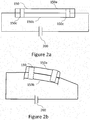
- FIG. 2a shows an example bimetallic strip 150.
- the bimetallic strip comprises a first strip 150a of a first metal and a first strip 150b of a second metal with a fixed connection 150c at each end.
- the first metal and second metal are different and expand at different rates when they are heated.
- the bimetallic strip 150 may be formed of any suitable metals which have different thermal expansion coefficients.
- the first metal may for example comprise steel and the second metal may comprise brass or copper.
- the bimetallic strip 150 is connected to a voltage supply 200. This may be for example a mains power supply which powers the refrigeration apparatus 100 as a whole, optionally passed through a voltage regulator or transformer as necessary, or some other, dedicated power supply.
- Figure 2b shows an example bimetallic strip 150 when a voltage is applied by voltage supply 200.
- a current flows through the bimetallic strip 150.
- the current flow causes heating of the bimetallic strip 150.
- the first strip 150a has a higher coefficient of thermal expansion than the second strip, resulting in bending of the bimetallic strip 150.
- the bending of the bimetallic strip exerts a force outwards from the inner surface. Force is thus exerted by the bimetallic strip on frost which has built up on the inner surface of the main body 110 of the refrigeration apparatus 100. Once the exerted force is high enough, the frost will break and defrost is achieved. The refrigeration apparatus 100 may then operate at normal performance levels.
- the refrigeration apparatus 100 comprises a controller (not shown).
- the controller comprises a memory and processor.
- the controller is operable to monitor operations of the refrigeration apparatus.
- the controller can monitor and control operations of one or more components of the refrigeration.
- the controller may be configured to operate a defrost control system.
- a defrost control system for a self-defrosting refrigerator is configured to monitor a compressor load, determine whether at least a first defrost cycle is required based on the compressor load, execute at least one defrost cycle when required; and regulate the defrost cycle to conserve energy.
- a controller is operatively coupled to a compressor, a voltage supply and a refrigeration compartment temperature sensor. The controller makes defrost decisions based on temperature conditions in the refrigeration compartment in light of other events, such as refrigerator door openings, completed defrost cycles, and power up events. Defrost cycles are automatically adjusted as operating conditions change, thereby avoiding unnecessary energy consumption that would otherwise occur in a fixed defrost cycle.
- Figure 3 shows a control method according to an example.
- the method comprises determining a requirement for a defrost process.
- the requirement for a defrost process may be determined as described above or in any other suitable manner.
- a voltage is applied to the bimetallic strips.
- the applied voltage causes a current flow in the bimetallic strips, resulting in heating of the bimetallic strips.
- the bimetallic strips bend. Bending of the bimetallic strips exerts a force outwards of the inner surface of the main body of the refrigeration apparatus and causes breakage of frost on the inner surface.
- the described apparatus and method provide a self-defrost mechanism for a refrigeration apparatus.
- processor or processing system or circuitry referred to herein may in practice be provided by a single chip or integrated circuit or plural chips or integrated circuits, optionally provided as a chipset, an application-specific integrated circuit (ASIC), field-programmable gate array (FPGA), digital signal processor (DSP), graphics processing units (GPUs), etc.
- the chip or chips may comprise circuitry (as well as possibly firmware) for embodying at least one or more of a data processor or processors, a digital signal processor or processors, baseband circuitry and radio frequency circuitry, which are configurable so as to operate in accordance with the exemplary embodiments.
- the exemplary embodiments may be implemented at least in part by computer software stored in (non-transitory) memory and executable by the processor, or by hardware, or by a combination of tangibly stored software and hardware (and tangibly stored firmware).
- the invention also extends to computer programs, particularly computer programs on or in a carrier, adapted for putting the invention into practice.
- the program may be in the form of non-transitory source code, object code, a code intermediate source and object code such as in partially compiled form, or in any other non-transitory form suitable for use in the implementation of processes according to the invention.
- the carrier may be any entity or device capable of carrying the program.
- the carrier may comprise a storage medium, such as a solid-state drive (SSD) or other semiconductor-based RAM; a ROM, for example a CD ROM or a semiconductor ROM; a magnetic recording medium, for example a floppy disk or hard disk; optical memory devices in general; etc.
- SSD solid-state drive
- ROM read-only memory
- magnetic recording medium for example a floppy disk or hard disk
- optical memory devices in general etc.
Landscapes
- Engineering & Computer Science (AREA)
- Chemical & Material Sciences (AREA)
- Combustion & Propulsion (AREA)
- Physics & Mathematics (AREA)
- Mechanical Engineering (AREA)
- Thermal Sciences (AREA)
- General Engineering & Computer Science (AREA)
- Defrosting Systems (AREA)
- Devices That Are Associated With Refrigeration Equipment (AREA)
Abstract
Description
- The present disclosure relates to a refrigeration apparatus and a method of defrosting a refrigeration apparatus.
- Refrigeration apparatus are known. Refrigeration apparatus operate to keep perishables, such as food and drink, cold or below a certain temperature. Known refrigeration apparatus include fridges and freezers.
- According to a first aspect disclosed herein, there is provided a refrigeration apparatus comprising a main body portion, at least one bimetallic strip arranged on an inner surface of the main body portion, the at least one bimetallic strip connectable to a voltage supply such that, on application of a voltage to the at least one bimetallic strip, the bimetallic strip deforms causing a force to be exerted outwards from the inner surface.
- According to an example, the apparatus comprises an evaporator coil located in the main body, wherein the at least one bimetallic strip is located in proximity to the evaporator coil.
- According to an example the evaporator coil comprises a cover panel and the at least one bimetallic strip is located on the cover panel.
- According to an example the main body comprises a plurality of bimetallic strips arranged on each of the inner surfaces of the main body.
- According to an example the bimetallic strip comprises a steel strip and a copper strip.
- According to an example, the apparatus comprises a controller configured to determine that a defrost process is required and, in response, apply a voltage to the bimetallic strips.
- According to an example, the controller is configured to determine that the defrost process is complete and, in response, stop applying the voltage to the bimetallic strip.
- According to an example, the main body comprises a closable box and comprising a plurality of bimetallic strips arranged on at least one of the interior walls of the box.
- According to an example, the refrigeration apparatus comprises a fridge and/or a freezer.
- According to a second aspect disclosed herein there is provided a method of defrosting a refrigeration apparatus, the method comprising determining that a defrost process is required and applying a voltage to a bimetallic strip located on an inner surface of the refrigeration apparatus to cause expansion of the bimetallic strip and a resulting force to be exerted outwards from the inner surface.
- According to an example, the method comprises determining that a defrost process is required based on at least one of load of a compressor of the refrigerator, temperature in a main body of the refrigeration apparatus and a trigger event.
- According to an example, the trigger event comprises at least one of a refrigerator door opening, a completed defrost process and a power up event.
- To assist understanding of the present disclosure and to show how embodiments may be put into effect, reference is made by way of example to the accompanying drawings in which:
-
Figure 1 shows schematically a refrigeration apparatus according to an example; -
Figure 2a shows schematically a bimetallic strip in connection with a voltage supply according to an example; -
Figure 2b shows schematically a bimetallic strip in connection with a voltage supply according to an example; -
Figure 3 shows a control method according to an example. - As briefly described above, refrigeration apparatus are known. Refrigeration apparatus are operate to keep perishables, such as food and drink, cold or below a certain temperature. Known refrigeration apparatus include fridges (also referred to as refrigerators) and freezers. Also known are combined fridge-freezers, which have separate fridge and freezer compartments. A known refrigeration apparatus includes a main body comprising a refrigeration compartment therein, a compressor for compressing and driving a refrigerant through a refrigeration circuit of the refrigeration apparatus and a controller. The refrigeration circuit of a refrigeration apparatus includes an evaporator. The evaporator is located inside the main body of a refrigeration apparatus.
- During the refrigeration cycle of a refrigerator, moisture in the air freezes and can stick to the surfaces within the refrigeration compartment, and, in particular, to the evaporator, as frost. The presence of frost reduces the efficiency of the evaporator and thus the refrigeration apparatus. Frost may also be seen on a panel covering the evaporator as well as the inner surfaces of the main body of the refrigeration apparatus. Frost may sometimes build up to the point that it blocks airflow and the refrigerator stops cooling completely.
- Self-defrost refrigeration apparatus are known. A self-defrost refrigeration apparatus is capable of performing a defrost process to melt the frost that builds up on the evaporator from the moisture in the air. The frost may be melted by passing a heated fluid through the evaporator. If the refrigerator has a defrost problem the frost collected on the coils will not melt.
-
Figure 1 shows arefrigeration apparatus 100 in accordance with an example. Therefrigeration apparatus 100 comprises amain body portion 110. Themain body portion 110 is in the form of a closable box which defines arefrigeration compartment 120. Therefrigeration compartment 120 is closable by adoor 130. Therefrigeration apparatus 100 includes a plurality ofbimetallic strips 150 arranged on the inner surface of themain body 110. Thebimetallic strips 150 are connected to a voltage supply (not shown). Therefrigeration apparatus 100 may be a fridge and/or a freezer. - In the example shown in
Figure 1 , a plurality ofbimetallic strips 150 are located on the inner surfaces of themain body portion 110. In a further example, at least onebimetallic strip 150 is located on an inner surface of the main body portion. The at least onebimetallic strip 150 may be located in proximity to the evaporator of a refrigeration device. The at least onebimetallic strip 150 may be located on the cover plate of an evaporator. -
Figure 2a shows an examplebimetallic strip 150. The bimetallic strip comprises afirst strip 150a of a first metal and afirst strip 150b of a second metal with afixed connection 150c at each end. The first metal and second metal are different and expand at different rates when they are heated. Thebimetallic strip 150 may be formed of any suitable metals which have different thermal expansion coefficients. The first metal may for example comprise steel and the second metal may comprise brass or copper. Thebimetallic strip 150 is connected to avoltage supply 200. This may be for example a mains power supply which powers therefrigeration apparatus 100 as a whole, optionally passed through a voltage regulator or transformer as necessary, or some other, dedicated power supply. -
Figure 2b shows an examplebimetallic strip 150 when a voltage is applied byvoltage supply 200. As a result of the applied voltage, a current flows through thebimetallic strip 150. The current flow causes heating of thebimetallic strip 150. Thefirst strip 150a has a higher coefficient of thermal expansion than the second strip, resulting in bending of thebimetallic strip 150. - In use, when a voltage is applied to the
bimetallic strips 150 arranged on an inner surface of therefrigeration apparatus 100, the bending of the bimetallic strip exerts a force outwards from the inner surface. Force is thus exerted by the bimetallic strip on frost which has built up on the inner surface of themain body 110 of therefrigeration apparatus 100. Once the exerted force is high enough, the frost will break and defrost is achieved. Therefrigeration apparatus 100 may then operate at normal performance levels. - The
refrigeration apparatus 100 comprises a controller (not shown). The controller comprises a memory and processor. In this example, the controller is operable to monitor operations of the refrigeration apparatus. For example, the controller can monitor and control operations of one or more components of the refrigeration. - The controller may be configured to operate a defrost control system. In an example defrost control system, a defrost control system for a self-defrosting refrigerator is configured to monitor a compressor load, determine whether at least a first defrost cycle is required based on the compressor load, execute at least one defrost cycle when required; and regulate the defrost cycle to conserve energy. A controller is operatively coupled to a compressor, a voltage supply and a refrigeration compartment temperature sensor. The controller makes defrost decisions based on temperature conditions in the refrigeration compartment in light of other events, such as refrigerator door openings, completed defrost cycles, and power up events. Defrost cycles are automatically adjusted as operating conditions change, thereby avoiding unnecessary energy consumption that would otherwise occur in a fixed defrost cycle.
-
Figure 3 shows a control method according to an example. - At S1, the method comprises determining a requirement for a defrost process. The requirement for a defrost process may be determined as described above or in any other suitable manner.
- At S2, once it is determined that a defrost process is required a voltage is applied to the bimetallic strips. The applied voltage causes a current flow in the bimetallic strips, resulting in heating of the bimetallic strips. On heating, the bimetallic strips bend. Bending of the bimetallic strips exerts a force outwards of the inner surface of the main body of the refrigeration apparatus and causes breakage of frost on the inner surface.
- At S3, it is determined that the defrost process is completed and the voltage is turned off.
- The described apparatus and method provide a self-defrost mechanism for a refrigeration apparatus.
- It will be understood that the processor or processing system or circuitry referred to herein may in practice be provided by a single chip or integrated circuit or plural chips or integrated circuits, optionally provided as a chipset, an application-specific integrated circuit (ASIC), field-programmable gate array (FPGA), digital signal processor (DSP), graphics processing units (GPUs), etc. The chip or chips may comprise circuitry (as well as possibly firmware) for embodying at least one or more of a data processor or processors, a digital signal processor or processors, baseband circuitry and radio frequency circuitry, which are configurable so as to operate in accordance with the exemplary embodiments. In this regard, the exemplary embodiments may be implemented at least in part by computer software stored in (non-transitory) memory and executable by the processor, or by hardware, or by a combination of tangibly stored software and hardware (and tangibly stored firmware).
- Although at least some aspects of the embodiments described herein with reference to the drawings comprise computer processes performed in processing systems or processors, the invention also extends to computer programs, particularly computer programs on or in a carrier, adapted for putting the invention into practice. The program may be in the form of non-transitory source code, object code, a code intermediate source and object code such as in partially compiled form, or in any other non-transitory form suitable for use in the implementation of processes according to the invention. The carrier may be any entity or device capable of carrying the program. For example, the carrier may comprise a storage medium, such as a solid-state drive (SSD) or other semiconductor-based RAM; a ROM, for example a CD ROM or a semiconductor ROM; a magnetic recording medium, for example a floppy disk or hard disk; optical memory devices in general; etc.
- The examples described herein are to be understood as illustrative examples of embodiments of the invention. Further embodiments and examples are envisaged. Any feature described in relation to any one example or embodiment may be used alone or in combination with other features. In addition, any feature described in relation to any one example or embodiment may also be used in combination with one or more features of any other of the examples or embodiments, or any combination of any other of the examples or embodiments. Furthermore, equivalents and modifications not described herein may also be employed within the scope of the invention, which is defined in the claims.
Claims (12)
- A refrigeration apparatus comprising:a main body portion;at least one bimetallic strip arranged on an inner surface of the main body portion, the at least one bimetallic strip connectable to a voltage supply such that, on application of a voltage to the at least one bimetallic strip, the bimetallic strip deforms causing a force to be exerted outwards from the inner surface.
- A refrigeration apparatus according to claim 1, comprising an evaporator coil located in the main body, wherein the at least one bimetallic strip is located in proximity to the evaporator coil.
- A refrigeration apparatus according to claim 2, wherein the evaporator coil comprises a cover panel and the at least one bimetallic strip is located on the cover panel.
- A refrigeration apparatus according to any of claims 1 to 3, wherein the main body comprises a plurality of bimetallic strips arranged on each of the inner surfaces of the main body.
- A refrigeration apparatus according to any of claims 1 to 4, wherein the bimetallic strip comprises a steel strip and a copper strip.
- A refrigeration apparatus according to any of claims 1 to 5, comprising a controller configured to determine that a defrost process is required and, in response, apply a voltage to the bimetallic strips.
- A refrigeration apparatus according to claim 6, the controller configured to determine that the defrost process is complete and, in response, stop applying the voltage to the bimetallic strip.
- A refrigeration apparatus according to any of claims 1 to 7, wherein the main body comprises a closable box and comprising a plurality of bimetallic strips arranged on at least one of the interior walls of the box.
- A refrigeration apparatus according to any of claims 1 to 8, the refrigeration apparatus comprising a fridge and/or a freezer.
- A method of defrosting a refrigeration apparatus, the method comprising:determining that a defrost process is required;applying a voltage to a bimetallic strip located on an inner surface of the refrigeration apparatus to cause expansion of the bimetallic strip and a resulting force to be exerted outwards from the inner surface.
- A method according to claim 10, wherein determining that a defrost process is required is based on at least one of load of a compressor of the refrigerator, temperature in a main body of the refrigeration apparatus and a trigger event.
- A method according to claim 11, wherein the trigger event comprises at least one of a refrigerator door opening, a completed defrost process and a power up event.
Priority Applications (2)
| Application Number | Priority Date | Filing Date | Title |
|---|---|---|---|
| EP17199134.2A EP3477229B1 (en) | 2017-10-30 | 2017-10-30 | Refrigeration apparatus and method of defrosting a refrigeration apparatus |
| TR2017/18963A TR201718963A2 (en) | 2017-10-30 | 2017-11-28 | COOLING APPARATUS AND METHOD OF DEFROSTING A COOLING APPARATUS |
Applications Claiming Priority (1)
| Application Number | Priority Date | Filing Date | Title |
|---|---|---|---|
| EP17199134.2A EP3477229B1 (en) | 2017-10-30 | 2017-10-30 | Refrigeration apparatus and method of defrosting a refrigeration apparatus |
Publications (2)
| Publication Number | Publication Date |
|---|---|
| EP3477229A1 true EP3477229A1 (en) | 2019-05-01 |
| EP3477229B1 EP3477229B1 (en) | 2021-04-28 |
Family
ID=60191246
Family Applications (1)
| Application Number | Title | Priority Date | Filing Date |
|---|---|---|---|
| EP17199134.2A Active EP3477229B1 (en) | 2017-10-30 | 2017-10-30 | Refrigeration apparatus and method of defrosting a refrigeration apparatus |
Country Status (2)
| Country | Link |
|---|---|
| EP (1) | EP3477229B1 (en) |
| TR (1) | TR201718963A2 (en) |
Citations (3)
| Publication number | Priority date | Publication date | Assignee | Title |
|---|---|---|---|---|
| GB750576A (en) * | 1954-07-12 | 1956-06-20 | Francis William Taylor | Improvements in methods of making ice and apparatus therefor |
| JPS6412168U (en) * | 1987-07-08 | 1989-01-23 | ||
| US20120297815A1 (en) * | 2011-05-24 | 2012-11-29 | General Electric Company | Ice Making Assembly with Bimetallic Actuating Element and Refrigeration Appliance Incorporating Same |
-
2017
- 2017-10-30 EP EP17199134.2A patent/EP3477229B1/en active Active
- 2017-11-28 TR TR2017/18963A patent/TR201718963A2/en unknown
Patent Citations (3)
| Publication number | Priority date | Publication date | Assignee | Title |
|---|---|---|---|---|
| GB750576A (en) * | 1954-07-12 | 1956-06-20 | Francis William Taylor | Improvements in methods of making ice and apparatus therefor |
| JPS6412168U (en) * | 1987-07-08 | 1989-01-23 | ||
| US20120297815A1 (en) * | 2011-05-24 | 2012-11-29 | General Electric Company | Ice Making Assembly with Bimetallic Actuating Element and Refrigeration Appliance Incorporating Same |
Also Published As
| Publication number | Publication date |
|---|---|
| TR201718963A2 (en) | 2019-05-21 |
| EP3477229B1 (en) | 2021-04-28 |
Similar Documents
| Publication | Publication Date | Title |
|---|---|---|
| EP2225507B1 (en) | Refrigerator and control method for the same | |
| EP3660425B1 (en) | Refrigerator and control method thereof | |
| EP2194346A2 (en) | Refrigerator and control method thereof | |
| EP3098547B1 (en) | Simple inverter-control-type refrigerator | |
| JP5884010B2 (en) | refrigerator | |
| CN111059861B (en) | Refrigeration control method of refrigerator and refrigerator | |
| US20070033956A1 (en) | Operation control method of refrigerator | |
| US7913500B2 (en) | Control method for a refrigerator | |
| CN106642922A (en) | Refrigeration control method for refrigerator and refrigerator | |
| KR101373568B1 (en) | Apparatus and method for controlling defrost of refrigeration and freezing system | |
| KR20000028026A (en) | Method of driving air curtain fan for refrigerator and device thereof | |
| CN101922846A (en) | A control system of a single-door frost-free refrigerator | |
| EP3477229B1 (en) | Refrigeration apparatus and method of defrosting a refrigeration apparatus | |
| JP2015042924A (en) | refrigerator | |
| EP1325271B1 (en) | Refrigerating apparatus control method | |
| KR101408771B1 (en) | Refrigerator defrosting method | |
| JP5262259B2 (en) | refrigerator | |
| JP2018009709A (en) | refrigerator | |
| JP2017020745A (en) | Cooling storage | |
| JP2014112002A (en) | Temperature control device and temperature control method for showcase | |
| KR20120134251A (en) | System for defrost in the refrigerator and method thereof | |
| JP5137742B2 (en) | refrigerator | |
| JP2018004146A (en) | Control method, controller, and showcase | |
| KR20150073824A (en) | Apparatus and Method for Freezing-Air Cooling System Control in Truck Refrigerator | |
| CA2753781A1 (en) | Refrigeration appliance with two evaporators in series and method for controlling such appliance |
Legal Events
| Date | Code | Title | Description |
|---|---|---|---|
| PUAI | Public reference made under article 153(3) epc to a published international application that has entered the european phase |
Free format text: ORIGINAL CODE: 0009012 |
|
| STAA | Information on the status of an ep patent application or granted ep patent |
Free format text: STATUS: THE APPLICATION HAS BEEN PUBLISHED |
|
| AK | Designated contracting states |
Kind code of ref document: A1 Designated state(s): AL AT BE BG CH CY CZ DE DK EE ES FI FR GB GR HR HU IE IS IT LI LT LU LV MC MK MT NL NO PL PT RO RS SE SI SK SM TR |
|
| AX | Request for extension of the european patent |
Extension state: BA ME |
|
| STAA | Information on the status of an ep patent application or granted ep patent |
Free format text: STATUS: REQUEST FOR EXAMINATION WAS MADE |
|
| 17P | Request for examination filed |
Effective date: 20191031 |
|
| RBV | Designated contracting states (corrected) |
Designated state(s): AL AT BE BG CH CY CZ DE DK EE ES FI FR GB GR HR HU IE IS IT LI LT LU LV MC MK MT NL NO PL PT RO RS SE SI SK SM TR |
|
| GRAP | Despatch of communication of intention to grant a patent |
Free format text: ORIGINAL CODE: EPIDOSNIGR1 |
|
| STAA | Information on the status of an ep patent application or granted ep patent |
Free format text: STATUS: GRANT OF PATENT IS INTENDED |
|
| INTG | Intention to grant announced |
Effective date: 20201130 |
|
| GRAS | Grant fee paid |
Free format text: ORIGINAL CODE: EPIDOSNIGR3 |
|
| GRAA | (expected) grant |
Free format text: ORIGINAL CODE: 0009210 |
|
| STAA | Information on the status of an ep patent application or granted ep patent |
Free format text: STATUS: THE PATENT HAS BEEN GRANTED |
|
| AK | Designated contracting states |
Kind code of ref document: B1 Designated state(s): AL AT BE BG CH CY CZ DE DK EE ES FI FR GB GR HR HU IE IS IT LI LT LU LV MC MK MT NL NO PL PT RO RS SE SI SK SM TR |
|
| REG | Reference to a national code |
Ref country code: GB Ref legal event code: FG4D |
|
| REG | Reference to a national code |
Ref country code: CH Ref legal event code: EP |
|
| REG | Reference to a national code |
Ref country code: AT Ref legal event code: REF Ref document number: 1387511 Country of ref document: AT Kind code of ref document: T Effective date: 20210515 |
|
| REG | Reference to a national code |
Ref country code: DE Ref legal event code: R096 Ref document number: 602017037491 Country of ref document: DE |
|
| REG | Reference to a national code |
Ref country code: IE Ref legal event code: FG4D |
|
| REG | Reference to a national code |
Ref country code: LT Ref legal event code: MG9D |
|
| REG | Reference to a national code |
Ref country code: AT Ref legal event code: MK05 Ref document number: 1387511 Country of ref document: AT Kind code of ref document: T Effective date: 20210428 |
|
| PG25 | Lapsed in a contracting state [announced via postgrant information from national office to epo] |
Ref country code: NL Free format text: LAPSE BECAUSE OF FAILURE TO SUBMIT A TRANSLATION OF THE DESCRIPTION OR TO PAY THE FEE WITHIN THE PRESCRIBED TIME-LIMIT Effective date: 20210428 Ref country code: HR Free format text: LAPSE BECAUSE OF FAILURE TO SUBMIT A TRANSLATION OF THE DESCRIPTION OR TO PAY THE FEE WITHIN THE PRESCRIBED TIME-LIMIT Effective date: 20210428 Ref country code: BG Free format text: LAPSE BECAUSE OF FAILURE TO SUBMIT A TRANSLATION OF THE DESCRIPTION OR TO PAY THE FEE WITHIN THE PRESCRIBED TIME-LIMIT Effective date: 20210728 Ref country code: AT Free format text: LAPSE BECAUSE OF FAILURE TO SUBMIT A TRANSLATION OF THE DESCRIPTION OR TO PAY THE FEE WITHIN THE PRESCRIBED TIME-LIMIT Effective date: 20210428 Ref country code: FI Free format text: LAPSE BECAUSE OF FAILURE TO SUBMIT A TRANSLATION OF THE DESCRIPTION OR TO PAY THE FEE WITHIN THE PRESCRIBED TIME-LIMIT Effective date: 20210428 Ref country code: LT Free format text: LAPSE BECAUSE OF FAILURE TO SUBMIT A TRANSLATION OF THE DESCRIPTION OR TO PAY THE FEE WITHIN THE PRESCRIBED TIME-LIMIT Effective date: 20210428 |
|
| PG25 | Lapsed in a contracting state [announced via postgrant information from national office to epo] |
Ref country code: IS Free format text: LAPSE BECAUSE OF FAILURE TO SUBMIT A TRANSLATION OF THE DESCRIPTION OR TO PAY THE FEE WITHIN THE PRESCRIBED TIME-LIMIT Effective date: 20210828 Ref country code: LV Free format text: LAPSE BECAUSE OF FAILURE TO SUBMIT A TRANSLATION OF THE DESCRIPTION OR TO PAY THE FEE WITHIN THE PRESCRIBED TIME-LIMIT Effective date: 20210428 Ref country code: GR Free format text: LAPSE BECAUSE OF FAILURE TO SUBMIT A TRANSLATION OF THE DESCRIPTION OR TO PAY THE FEE WITHIN THE PRESCRIBED TIME-LIMIT Effective date: 20210729 Ref country code: SE Free format text: LAPSE BECAUSE OF FAILURE TO SUBMIT A TRANSLATION OF THE DESCRIPTION OR TO PAY THE FEE WITHIN THE PRESCRIBED TIME-LIMIT Effective date: 20210428 Ref country code: RS Free format text: LAPSE BECAUSE OF FAILURE TO SUBMIT A TRANSLATION OF THE DESCRIPTION OR TO PAY THE FEE WITHIN THE PRESCRIBED TIME-LIMIT Effective date: 20210428 Ref country code: PT Free format text: LAPSE BECAUSE OF FAILURE TO SUBMIT A TRANSLATION OF THE DESCRIPTION OR TO PAY THE FEE WITHIN THE PRESCRIBED TIME-LIMIT Effective date: 20210830 Ref country code: NO Free format text: LAPSE BECAUSE OF FAILURE TO SUBMIT A TRANSLATION OF THE DESCRIPTION OR TO PAY THE FEE WITHIN THE PRESCRIBED TIME-LIMIT Effective date: 20210728 Ref country code: PL Free format text: LAPSE BECAUSE OF FAILURE TO SUBMIT A TRANSLATION OF THE DESCRIPTION OR TO PAY THE FEE WITHIN THE PRESCRIBED TIME-LIMIT Effective date: 20210428 |
|
| REG | Reference to a national code |
Ref country code: NL Ref legal event code: MP Effective date: 20210428 |
|
| PG25 | Lapsed in a contracting state [announced via postgrant information from national office to epo] |
Ref country code: SK Free format text: LAPSE BECAUSE OF FAILURE TO SUBMIT A TRANSLATION OF THE DESCRIPTION OR TO PAY THE FEE WITHIN THE PRESCRIBED TIME-LIMIT Effective date: 20210428 Ref country code: SM Free format text: LAPSE BECAUSE OF FAILURE TO SUBMIT A TRANSLATION OF THE DESCRIPTION OR TO PAY THE FEE WITHIN THE PRESCRIBED TIME-LIMIT Effective date: 20210428 Ref country code: EE Free format text: LAPSE BECAUSE OF FAILURE TO SUBMIT A TRANSLATION OF THE DESCRIPTION OR TO PAY THE FEE WITHIN THE PRESCRIBED TIME-LIMIT Effective date: 20210428 Ref country code: CZ Free format text: LAPSE BECAUSE OF FAILURE TO SUBMIT A TRANSLATION OF THE DESCRIPTION OR TO PAY THE FEE WITHIN THE PRESCRIBED TIME-LIMIT Effective date: 20210428 Ref country code: DK Free format text: LAPSE BECAUSE OF FAILURE TO SUBMIT A TRANSLATION OF THE DESCRIPTION OR TO PAY THE FEE WITHIN THE PRESCRIBED TIME-LIMIT Effective date: 20210428 Ref country code: RO Free format text: LAPSE BECAUSE OF FAILURE TO SUBMIT A TRANSLATION OF THE DESCRIPTION OR TO PAY THE FEE WITHIN THE PRESCRIBED TIME-LIMIT Effective date: 20210428 Ref country code: ES Free format text: LAPSE BECAUSE OF FAILURE TO SUBMIT A TRANSLATION OF THE DESCRIPTION OR TO PAY THE FEE WITHIN THE PRESCRIBED TIME-LIMIT Effective date: 20210428 |
|
| REG | Reference to a national code |
Ref country code: DE Ref legal event code: R097 Ref document number: 602017037491 Country of ref document: DE |
|
| PLBE | No opposition filed within time limit |
Free format text: ORIGINAL CODE: 0009261 |
|
| STAA | Information on the status of an ep patent application or granted ep patent |
Free format text: STATUS: NO OPPOSITION FILED WITHIN TIME LIMIT |
|
| 26N | No opposition filed |
Effective date: 20220131 |
|
| REG | Reference to a national code |
Ref country code: CH Ref legal event code: PL |
|
| PG25 | Lapsed in a contracting state [announced via postgrant information from national office to epo] |
Ref country code: IS Free format text: LAPSE BECAUSE OF FAILURE TO SUBMIT A TRANSLATION OF THE DESCRIPTION OR TO PAY THE FEE WITHIN THE PRESCRIBED TIME-LIMIT Effective date: 20210828 Ref country code: AL Free format text: LAPSE BECAUSE OF FAILURE TO SUBMIT A TRANSLATION OF THE DESCRIPTION OR TO PAY THE FEE WITHIN THE PRESCRIBED TIME-LIMIT Effective date: 20210428 |
|
| REG | Reference to a national code |
Ref country code: BE Ref legal event code: MM Effective date: 20211031 |
|
| PG25 | Lapsed in a contracting state [announced via postgrant information from national office to epo] |
Ref country code: MC Free format text: LAPSE BECAUSE OF FAILURE TO SUBMIT A TRANSLATION OF THE DESCRIPTION OR TO PAY THE FEE WITHIN THE PRESCRIBED TIME-LIMIT Effective date: 20210428 |
|
| PG25 | Lapsed in a contracting state [announced via postgrant information from national office to epo] |
Ref country code: LU Free format text: LAPSE BECAUSE OF NON-PAYMENT OF DUE FEES Effective date: 20211030 Ref country code: IT Free format text: LAPSE BECAUSE OF FAILURE TO SUBMIT A TRANSLATION OF THE DESCRIPTION OR TO PAY THE FEE WITHIN THE PRESCRIBED TIME-LIMIT Effective date: 20210428 Ref country code: BE Free format text: LAPSE BECAUSE OF NON-PAYMENT OF DUE FEES Effective date: 20211031 |
|
| PG25 | Lapsed in a contracting state [announced via postgrant information from national office to epo] |
Ref country code: LI Free format text: LAPSE BECAUSE OF NON-PAYMENT OF DUE FEES Effective date: 20211031 Ref country code: CH Free format text: LAPSE BECAUSE OF NON-PAYMENT OF DUE FEES Effective date: 20211031 |
|
| PG25 | Lapsed in a contracting state [announced via postgrant information from national office to epo] |
Ref country code: FR Free format text: LAPSE BECAUSE OF NON-PAYMENT OF DUE FEES Effective date: 20211031 |
|
| PG25 | Lapsed in a contracting state [announced via postgrant information from national office to epo] |
Ref country code: IE Free format text: LAPSE BECAUSE OF NON-PAYMENT OF DUE FEES Effective date: 20211030 |
|
| PG25 | Lapsed in a contracting state [announced via postgrant information from national office to epo] |
Ref country code: CY Free format text: LAPSE BECAUSE OF FAILURE TO SUBMIT A TRANSLATION OF THE DESCRIPTION OR TO PAY THE FEE WITHIN THE PRESCRIBED TIME-LIMIT Effective date: 20210428 |
|
| PG25 | Lapsed in a contracting state [announced via postgrant information from national office to epo] |
Ref country code: HU Free format text: LAPSE BECAUSE OF FAILURE TO SUBMIT A TRANSLATION OF THE DESCRIPTION OR TO PAY THE FEE WITHIN THE PRESCRIBED TIME-LIMIT; INVALID AB INITIO Effective date: 20171030 |
|
| PG25 | Lapsed in a contracting state [announced via postgrant information from national office to epo] |
Ref country code: MK Free format text: LAPSE BECAUSE OF FAILURE TO SUBMIT A TRANSLATION OF THE DESCRIPTION OR TO PAY THE FEE WITHIN THE PRESCRIBED TIME-LIMIT Effective date: 20210428 |
|
| PG25 | Lapsed in a contracting state [announced via postgrant information from national office to epo] |
Ref country code: MT Free format text: LAPSE BECAUSE OF FAILURE TO SUBMIT A TRANSLATION OF THE DESCRIPTION OR TO PAY THE FEE WITHIN THE PRESCRIBED TIME-LIMIT Effective date: 20210428 |
|
| REG | Reference to a national code |
Ref country code: DE Ref legal event code: R082 Ref document number: 602017037491 Country of ref document: DE Representative=s name: WESTPHAL, MUSSGNUG & PARTNER PATENTANWAELTE MI, DE |
|
| PGFP | Annual fee paid to national office [announced via postgrant information from national office to epo] |
Ref country code: DE Payment date: 20251021 Year of fee payment: 9 |
|
| PGFP | Annual fee paid to national office [announced via postgrant information from national office to epo] |
Ref country code: GB Payment date: 20251021 Year of fee payment: 9 |
|
| PGFP | Annual fee paid to national office [announced via postgrant information from national office to epo] |
Ref country code: TR Payment date: 20251030 Year of fee payment: 9 |