EP3477223A1 - Cryogenic system - Google Patents
Cryogenic system Download PDFInfo
- Publication number
- EP3477223A1 EP3477223A1 EP18200885.4A EP18200885A EP3477223A1 EP 3477223 A1 EP3477223 A1 EP 3477223A1 EP 18200885 A EP18200885 A EP 18200885A EP 3477223 A1 EP3477223 A1 EP 3477223A1
- Authority
- EP
- European Patent Office
- Prior art keywords
- refrigerant
- refrigerant circulation
- refrigerator
- stage
- cryogenic
- Prior art date
- Legal status (The legal status is an assumption and is not a legal conclusion. Google has not performed a legal analysis and makes no representation as to the accuracy of the status listed.)
- Granted
Links
Images



Classifications
-
- F—MECHANICAL ENGINEERING; LIGHTING; HEATING; WEAPONS; BLASTING
- F25—REFRIGERATION OR COOLING; COMBINED HEATING AND REFRIGERATION SYSTEMS; HEAT PUMP SYSTEMS; MANUFACTURE OR STORAGE OF ICE; LIQUEFACTION SOLIDIFICATION OF GASES
- F25B—REFRIGERATION MACHINES, PLANTS OR SYSTEMS; COMBINED HEATING AND REFRIGERATION SYSTEMS; HEAT PUMP SYSTEMS
- F25B9/00—Compression machines, plants or systems, in which the refrigerant is air or other gas of low boiling point
- F25B9/10—Compression machines, plants or systems, in which the refrigerant is air or other gas of low boiling point with several cooling stages
-
- F—MECHANICAL ENGINEERING; LIGHTING; HEATING; WEAPONS; BLASTING
- F25—REFRIGERATION OR COOLING; COMBINED HEATING AND REFRIGERATION SYSTEMS; HEAT PUMP SYSTEMS; MANUFACTURE OR STORAGE OF ICE; LIQUEFACTION SOLIDIFICATION OF GASES
- F25B—REFRIGERATION MACHINES, PLANTS OR SYSTEMS; COMBINED HEATING AND REFRIGERATION SYSTEMS; HEAT PUMP SYSTEMS
- F25B9/00—Compression machines, plants or systems, in which the refrigerant is air or other gas of low boiling point
- F25B9/02—Compression machines, plants or systems, in which the refrigerant is air or other gas of low boiling point using Joule-Thompson effect; using vortex effect
-
- F—MECHANICAL ENGINEERING; LIGHTING; HEATING; WEAPONS; BLASTING
- F25—REFRIGERATION OR COOLING; COMBINED HEATING AND REFRIGERATION SYSTEMS; HEAT PUMP SYSTEMS; MANUFACTURE OR STORAGE OF ICE; LIQUEFACTION SOLIDIFICATION OF GASES
- F25B—REFRIGERATION MACHINES, PLANTS OR SYSTEMS; COMBINED HEATING AND REFRIGERATION SYSTEMS; HEAT PUMP SYSTEMS
- F25B9/00—Compression machines, plants or systems, in which the refrigerant is air or other gas of low boiling point
- F25B9/14—Compression machines, plants or systems, in which the refrigerant is air or other gas of low boiling point characterised by the cycle used, e.g. Stirling cycle
-
- F—MECHANICAL ENGINEERING; LIGHTING; HEATING; WEAPONS; BLASTING
- F25—REFRIGERATION OR COOLING; COMBINED HEATING AND REFRIGERATION SYSTEMS; HEAT PUMP SYSTEMS; MANUFACTURE OR STORAGE OF ICE; LIQUEFACTION SOLIDIFICATION OF GASES
- F25D—REFRIGERATORS; COLD ROOMS; ICE-BOXES; COOLING OR FREEZING APPARATUS NOT OTHERWISE PROVIDED FOR
- F25D19/00—Arrangement or mounting of refrigeration units with respect to devices or objects to be refrigerated, e.g. infrared detectors
- F25D19/006—Thermal coupling structure or interface
-
- F—MECHANICAL ENGINEERING; LIGHTING; HEATING; WEAPONS; BLASTING
- F25—REFRIGERATION OR COOLING; COMBINED HEATING AND REFRIGERATION SYSTEMS; HEAT PUMP SYSTEMS; MANUFACTURE OR STORAGE OF ICE; LIQUEFACTION SOLIDIFICATION OF GASES
- F25B—REFRIGERATION MACHINES, PLANTS OR SYSTEMS; COMBINED HEATING AND REFRIGERATION SYSTEMS; HEAT PUMP SYSTEMS
- F25B2309/00—Gas cycle refrigeration machines
- F25B2309/14—Compression machines, plants or systems characterised by the cycle used
- F25B2309/1428—Control of a Stirling refrigeration machine
-
- F—MECHANICAL ENGINEERING; LIGHTING; HEATING; WEAPONS; BLASTING
- F25—REFRIGERATION OR COOLING; COMBINED HEATING AND REFRIGERATION SYSTEMS; HEAT PUMP SYSTEMS; MANUFACTURE OR STORAGE OF ICE; LIQUEFACTION SOLIDIFICATION OF GASES
- F25B—REFRIGERATION MACHINES, PLANTS OR SYSTEMS; COMBINED HEATING AND REFRIGERATION SYSTEMS; HEAT PUMP SYSTEMS
- F25B2400/00—Component parts or details not otherwise provided for in this subclass
- F25B2400/06—Several compression cycles arranged in parallel
Definitions
- Certain embodiments of the present invention relate to a cryogenic system.
- cryogenic coolers have been used to cool various objects to be cooled to a desired very low temperature.
- cryogenic coolers there are a cooler that directly cools an object to be cooled by a mechanical refrigerator, such as a GM refrigerator, a Stirling refrigerator, or a pulse tube refrigerator, a cooler that cools a refrigerant by such a mechanical refrigerator and cools an object to be cooled by a refrigerant, and the like.
- An example of the related art includes Japanese Unexamined Patent Application Publication No. 2016-211795 .
- a plurality of individual refrigerant circulation paths between which a refrigerant cannot be circulated are formed in a refrigerant cooling type cryogenic cooler.
- the cryogenic cooler includes a plurality of mechanical refrigerators, and the refrigerator is installed on each refrigerant circulation path to cool a refrigerant that is circulated in each refrigerant circulation path. In a case in which a function to cool a certain refrigerant circulation path is lost due to the failure of any one of the refrigerators or other reasons, the cooling capacity of the refrigerant circulation path is lost.
- the refrigerator is a structure that connects a high-temperature section (for example, a room-temperature section) to a low-temperature section (for example, an object to be cooled)
- a refrigerator which is stopped due to a failure or the like, forms a heat transfer path to the low-temperature section from the high-temperature section.
- the refrigerator causes an increase in the penetration of heat into the object to be cooled.
- the cryogenic cooler cannot continue to perform desired cryogenic cooling or it may be difficult for the cryogenic cooler to perform desired cryogenic cooling.
- An exemplary object of an aspect of the invention is to improve the continuity of the cooling operation of a cryogenic system.
- a cryogenic system includes a cryogenic cooling unit, a plurality of refrigerant circulation loops which are adapted to cool the cryogenic cooling unit by heat exchange between the cryogenic cooling unit and a refrigerant and each of which includes a circulation pump circulating the refrigerant and a mechanical refrigerator cooling the refrigerant, and a connection line that connects the plurality of refrigerant circulation loops to allow the refrigerant to be circulated.
- connection line is adapted to be switchable to a connected state from an unconnected state, isolates the plurality of refrigerant circulation loops from each other in the unconnected state so that the circulation pump of each refrigerant circulation loop circulates the refrigerant in the refrigerant circulation loop, and connects the plurality of refrigerant circulation loops in the connected state so that the circulation pump of at least one refrigerant circulation loop circulates the refrigerant in at least one of the other refrigerant circulation loops as well.
- the continuity of the cooling operation of a cryogenic system can be improved.
- FIG. 1 is a diagram schematically showing a cryogenic system 10 according to an embodiment.
- the cryogenic system 10 includes a plurality of refrigerant circulation loops 12, a connection line 14, a vacuum vessel 16, and a cryogenic cooling unit 20 that cools an object 18 to be cooled.
- a radiation shield which is used to suppress the incidence of radiant heat on the object 18 to be cooled and the cryogenic cooling unit 20, is usually installed in the vacuum vessel 16, but is not shown for simplification.
- the refrigerant circulation loops 12 are adapted to cool the cryogenic cooling unit 20 by heat exchange between the cryogenic cooling unit 20 and a refrigerant.
- the refrigerant is, for example, a refrigerant gas (for example, helium) .
- Each of the plurality of refrigerant circulation loops 12 circulates the refrigerant.
- the connection line 14 connects the plurality of refrigerant circulation loops 12 so that the refrigerant can be circulated.
- the exemplary structures of the refrigerant circulation loops 12 and the connection line 14 will be described later.
- the vacuum vessel 16 is a cryogenic vacuum vessel, such as a cryostat, and partitions the cryogenic system 10 into a normal-temperature section 22 and a low-temperature section 24. That is, the normal-temperature section 22 of the cryogenic system 10 is disposed outside the vacuum vessel 16, and the low-temperature section 24 of the cryogenic system 10 is disposed in the vacuum vessel 16.
- the normal-temperature section 22 takes, for example, a room temperature or a temperature of about 300K.
- the object 18 to be cooled is a detection element that detects infrared rays, submillimeter waves, X-rays, or other electromagnetic waves, and such a detection element is a component of an observation device that is used for astronomical observation.
- the object 18 to be cooled is in physical contact with the cryogenic cooling unit 20 and is thermally coupled to the cryogenic cooling unit 20, or is thermally coupled to the cryogenic cooling unit 20 through a heat transfer member.
- the cryogenic cooling unit 20 is also called a cooling stage. As shown in FIG. 1 , the cryogenic system 10 may include one common cooling stage as the cryogenic cooling unit 20. Alternatively, the cryogenic cooling unit 20 may include a plurality of cooling stages. In this case, each of the refrigerant circulation loops 12 may be provided with the cooling stage (for example, see FIG. 4 ) .
- the cryogenic system 10 is adapted to be capable of being mounted on, for example, a spacecraft, such as an artificial satellite, together with the object 18 to be cooled.
- the cryogenic system 10 may be mounted on a ground facility including the object 18 to be cooled.
- the cryogenic system 10 may be mounted on a spacecraft or a ground facility together with, for example, a superconducting device or other objects 18 to be cooled for which a cryogenic environment is desirable.
- the refrigerant circulation loops 12 include a first refrigerant circulation loop 12a and a second refrigerant circulation loop 12b. Since these refrigerant circulation loops 12 have the same configuration, the configuration of the first refrigerant circulation loop 12a will be mainly described below and the description of the second refrigerant circulation loop 12b will be appropriately omitted.
- the first refrigerant circulation loop 12a includes a circulation pump 26 that circulates a refrigerant and a mechanical refrigerator (hereinafter, simply referred to as a refrigerator) 28 that cools the refrigerant.
- a circulation pump 26 that circulates a refrigerant
- a mechanical refrigerator hereinafter, simply referred to as a refrigerator
- the circulation pump 26 is adapted to increase the pressure of a refrigerant gas, which is collected from, for example, the low-temperature section 24, to, for example, about the atmospheric pressure or about several atmospheres.
- the circulation pump 26 can recover a pressure loss that occurs on the refrigerant in the refrigerant circulation loop 12.
- the circulation pump 26 may be a pump of which the output is lower than the output of a compressor 30 to be described later (for example, by about several W) .
- the circulation pump 26 is disposed in the normal-temperature section 22 of the cryogenic system 10.
- the refrigerator 28 is a two-stage Stirling refrigerator.
- the refrigerator 28 includes a compressor 30, a two-stage cold head 32 as an expander, and a connecting pipe 34 that connects the compressor 30 to the two-stage cold head 32.
- the connecting pipe 34 provides a gas flow channel that circulates a refrigerant gas (for example, a helium gas) between the compressor 30 and the two-stage cold head 32.
- the two-stage cold head 32 includes a first-stage refrigerator stage 36 and a second-stage refrigerator stage 38.
- the normal-temperature section 22 of the cryogenic system 10 includes the compressor 30, a room-temperature portion of the two-stage cold head 32, and the connecting pipe 34, and the low-temperature section 24 of the cryogenic system 10 includes the first-stage refrigerator stage 36 and the second-stage refrigerator stage 38.
- the compressor 30 is adapted to generate the pressure oscillation of a refrigerant gas.
- the generated pressure oscillation is transmitted to the two-stage cold head 32 through the connecting pipe 34.
- the two-stage cold head 32 is adapted to induce pressure oscillation where the pressure oscillation transmitted from the compressor 30 has a phase difference at the same frequency as the pressure oscillation in the two-stage cold head 32. Accordingly, a refrigeration cycle (specifically, reverse Stirling cycle) is formed between the compressor 30 and the two-stage cold head 32.
- the first-stage cooling temperature of the refrigerator 28 is selected from the temperature range of, for example, 50K to 150K.
- the first-stage cooling temperature maybe in the temperature range of, for example, 80K to 120K.
- the second-stage cooling temperature is lower than the first-stage cooling temperature.
- the second-stage cooling temperature is selected from the temperature range of, for example, 4K to 25K.
- the second-stage cooling temperature may be in the temperature range of, for example, 10K to 20K.
- the second-stage cooling temperature may be lower than 4K (for example, in the range of 1K to 4K).
- the first refrigerant circulation loop 12a further includes a first heat exchanger 40, a first-stage cooling unit 42, a second heat exchanger 44, a second-stage cooling unit 46, and a cooling-stage heat exchanger 48.
- the first heat exchanger 40, the first-stage cooling unit 42, the second heat exchanger 44, the second-stage cooling unit 46, and the cooling-stage heat exchanger 48 are disposed in the vacuum vessel 16, that is, in the low-temperature section 24 of the cryogenic system 10.
- the first refrigerant circulation loop 12a further includes a refrigerant supply line 50 and a refrigerant collection line 52.
- the refrigerant supply line 50 connects the discharge side of the circulation pump 26 to the supply side of the cooling-stage heat exchanger 48
- the refrigerant collection line 52 connects the collection side of the cooling-stage heat exchanger 48 to the suction side of the circulation pump 26. Accordingly, a part of each of the refrigerant supply line 50 and the refrigerant collection line 52 is disposed in the normal-temperature section 22, and the remaining part thereof is disposed in the low-temperature section 24.
- the refrigerant supply line 50 includes a supply-side refrigerant pipe 51 in the low-temperature section 24, and the refrigerant collection line 52 includes a collection-side refrigerant pipe 53 in the low-temperature section 24 (for example, pipes surrounded in FIG. 1 by a broken line) .
- the supply-side refrigerant pipe 51 connects the second-stage cooling unit 46 to the cooling-stage heat exchanger 48
- the collection-side refrigerant pipe 53 connects the cooling-stage heat exchanger 48 to a collection-side flow channel of the second heat exchanger 44.
- a refrigerant is supplied to the cooling-stage heat exchanger 48 from the second-stage cooling unit 46 through the supply-side refrigerant pipe 51, and the refrigerant is collected to the second heat exchanger 44 from the cooling-stage heat exchanger 48 through the collection-side refrigerant pipe 53.
- the first heat exchanger 40 cools a high-temperature (for example, a normal temperature, for example, about 300K) refrigerant gas that flows into the vacuum vessel 16 from the circulation pump 26.
- the second heat exchanger 44 further cools the refrigerant that is cooled by the first heat exchanger 40 and the first-stage cooling unit 42.
- Each of the first and second heat exchangers 40 and 44 is a counterflow heat exchanger.
- the refrigerant supply line 50 includes a supply-side flow channel of each of the first and second heat exchangers 40 and 44
- the refrigerant collection line 52 includes a collection-side flow channel of each of the first and second heat exchangers 40 and 44.
- a refrigerant, which flows through the supply-side flow channel, can be cooled in each heat exchanger by heat exchange between the supply-side flow channel and the collection-side flow channel.
- the first-stage cooling unit 42 is thermally coupled to the first-stage refrigerator stage 36.
- a refrigerant, which flows through the first-stage cooling unit 42, is cooled by heat exchange with the first-stage refrigerator stage 36.
- the first-stage cooling unit 42 is disposed on the refrigerant supply line 50 between the first and second heat exchangers 40 and 44.
- the second-stage cooling unit 46 is thermally coupled to the second-stage refrigerator stage 38.
- a refrigerant, which flows through the second-stage cooling unit 46, is cooled by the second-stage refrigerator stage 38.
- the second-stage cooling unit 46 is disposed on the refrigerant supply line 50 between the second heat exchanger 44 and the cooling-stage heat exchanger 48.
- the cooling-stage heat exchanger 48 is thermally coupled to the cryogenic cooling unit 20.
- a refrigerant which flows through the cooling-stage heat exchanger 48, cools the cryogenic cooling unit 20.
- the second refrigerant circulation loop 12b includes a circulation pump 26 and a refrigerator 28.
- the refrigerator 28 includes a compressor 30, a two-stage cold head 32, and a connecting pipe 34.
- the two-stage cold head 32 includes a first-stage refrigerator stage 36 and a second-stage refrigerator stage 38.
- the second refrigerant circulation loop 12b includes a first heat exchanger 40, a first-stage cooling unit 42, a second heat exchanger 44, a second-stage cooling unit 46, a cooling-stage heat exchanger 48, a refrigerant supply line 50, and a refrigerant collection line 52.
- the first refrigerant circulation loop 12a includes a backflow prevention unit 54.
- the backflow prevention unit 54 includes a pair of on-off valves (V1 andV2) for backflow prevention.
- One on-off valve V1 for backflow prevention is provided on the refrigerant collection line 52, and the other on-off valve V2 for backflow prevention is provided on the refrigerant supply line 50.
- the on-off valves (V1 and V2) for backflow prevention are opened in an unconnected state of the connection line 14.
- the on-off valves (V1 and V2) for backflow prevention are closed in a connected state of the connection line 14. The details of the unconnected state and the connected state of the connection line 14 will be described later.
- V1 and V2 on-off valves for backflow prevention are provided on the upstream side and the downstream side of the circulation pump 26, respectively.
- only one on-off valve for backflow prevention may be provided, and any one of the on-off valves (V1 and V2) for backflow prevention may be provided in this case.
- the second refrigerant circulation loop 12b also includes a backflow prevention unit 54.
- On-off valves for backflow prevention of the second refrigerant circulation loop 12b are denoted by V5 and V6 for convenience so as to be distinguished from the on-off valves (V1 and V2) for backflow prevention of the first refrigerant circulation loop 12a. Only one on-off valve for backflow prevention may be provided on the second refrigerant circulation loop 12b as well, and any one of the on-off valves (V5 and V6) for backflow prevention may be provided in this case.
- the circulation of the backflow of a refrigerant in each refrigerant circulation loop 12 can be prevented by a relatively simple structure of closing the on-off valves (V1, V2, V5, and V6) for backflow prevention.
- the backflow prevention units 54 are disposed in the normal-temperature section 22 of the cryogenic system 10. For this reason, a general-purpose component of which the operational reliability is ensured under a normal temperature can be employed as the backflow prevention unit 54. Such a general-purpose component can be available at a lower cost than a component of which the reliability in a cryogenic environment is ensured.
- the backflow prevention units 54 may be disposed in the low-temperature section 24 of the cryogenic system 10, if possible.
- connection line 14 is adapted to be switchable to the connected state from the unconnected state.
- the connection line 14 isolates the plurality of refrigerant circulation loops 12 from each other in the unconnected state so that the circulation pump 26 of each refrigerant circulation loop 12 circulates a refrigerant in the refrigerant circulation loop 12.
- the connection line 14 connects the plurality of refrigerant circulation loops 12 in the connected state so that the circulation pump 26 of at least one refrigerant circulation loop 12 circulates a refrigerant in at least one of the other refrigerant circulation loops 12 as well.
- the connection line 14 can also return to the unconnected state from the connected state.
- connection line 14 includes connection flow channels that connect the two refrigerant circulation loops 12 and on-off valves (V3 and V4) for connection that are provided on the connection flow channels, are closed in the unconnected state, and are opened in the connected state.
- the connected state and the unconnected state of the connection line 14 can be switched by a relatively simple structure of opening and closing the on-off valves (V3 and V4) for connection.
- connection line 14 includes a supply-side connection flow channel 56 that connects the refrigerant supply lines 50 of the two refrigerant circulation loops 12 and a supply-side on-off valve V3 for connection that is provided on the supply-side connection flow channel 56.
- connection line 14 includes a collection-side connection flow channel 58 that connects the refrigerant collection lines 52 of the two refrigerant circulation loops 12 and a collection-side on-off valve V4 for connection that is provided on the collection-side connection flow channel 58. Both the supply-side on-off valve V3 for connection and the collection-side on-off valve V4 for connection are closed in the unconnected state, and are opened in the connected state.
- a supply-side junction 60 between the refrigerant supply line 50 and the supply-side connection flow channel 56 is disposed between the on-off valve V2 for backflow prevention and the supply-side flow channel of the first heat exchanger 40. Accordingly, the on-off valve V2 for backflow prevention is disposed between the discharge side of the circulation pump 26 and the supply-side junction 60. Further, a collection-side junction 62 between the refrigerant collection line 52 and the collection-side connection flow channel 58 is disposed between the on-off valve V1 for backflow prevention and the collection-side flow channel of the first heat exchanger 40. Accordingly, the on-off valve V1 for backflow prevention is disposed between the suction side of the circulation pump 26 and the collection-side junction 62.
- connection line 14 is disposed in the normal-temperature section 22 of the cryogenic system 10. Accordingly, general-purpose components of which the operational reliability is ensured under a normal temperature can be employed as the on-off valves (V3 and V4) for connection or the other components of the connection line 14. Such a general-purpose component can be available at a lower cost than a component of which the reliability in a cryogenic environment is ensured.
- the connection line 14 may be disposed in the low-temperature section 24 of the cryogenic system 10, if possible.
- the respective on-off valves (V1 to V6) provided on the refrigerant circulation loops 12 and the connection line 14 are opened, a refrigerant can flow through the on-off valves.
- the respective on-off valves (V1 to V6) are closed, a refrigerant cannot flow through the on-off valves.
- the respective on-off valves (V1 to V6) may be electromagnetic on-off valves, mechanical on-off valves, manual on-off valves, or other driven-type on-off valves .
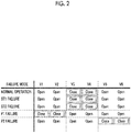
- FIG. 2 is a table illustrating a relationship between failure modes of the cryogenic system 10 according to the embodiment and the state of the connection line 14.
- the open/closed states of the respective on-off valves (V1 to V6) of the connection line 14 are shown so as to correspond to some failure modes.
- "open” represents that the on-off valve is opened and “close” represents that the on-off valve is closed.
- FIG. 2 A normal operation and four failure modes of the cryogenic system 10 are exemplified in FIG. 2 .
- Normal operation represents that all the circulation pumps 26 and the refrigerators 28 provided in the cryogenic system 10 are normally operated without a failure .
- ST1 failure represents that a failure occurs in the refrigerator 28 of the first refrigerant circulation loop 12a
- ST2 failure represents that a failure occurs in the refrigerator 28 of the second refrigerant circulation loop 12b.
- P1 failure represents that a failure occurs in the circulation pump 26 of the first refrigerant circulation loop 12a
- P2 failure represents that a failure occurs in the circulation pump 26 of the second refrigerant circulation loop 12b.
- a temperature sensor 64 which measures the temperature of the refrigerator stage, is usually installed on at least one of the first-stage refrigerator stage 36 and the second-stage refrigerator stage 38, it is possible to determine whether or not a failure occurs in the refrigerator 28 from the measurement result of the temperature sensor 64.
- a refrigerant sensor 66 such as a pressure sensor for measuring the pressure of a refrigerant (and/or a flow sensor for measuring the flow rate of a refrigerant), is usually installed on the refrigerant circulation loop 12, it is possible to determine whether or not a failure occurs in the circulation pump 26 from the measurement result of the refrigerant sensor 66.
- the circulation pump 26 of the first refrigerant circulation loop 12a circulates a refrigerant in the first refrigerant circulation loop 12a and the circulation pump 26 of the second refrigerant circulation loop 12b circulates a refrigerant in the second refrigerant circulation loop 12b.
- a refrigerant does not flow in the connection line 14, and is not circulated between the first refrigerant circulation loop 12a and the second refrigerant circulation loop 12b. In this way, the plurality of refrigerant circulation loops 12 are operated independently of each other.
- a refrigerant which is sent to the refrigerant supply line 50 from the circulation pump 26 of each refrigerant circulation loop 12, flows into the vacuum vessel 16 and is supplied to the supply-side flow channel of the first heat exchanger 40 for the first time.
- the refrigerant which flows through the supply-side flow channel of the first heat exchanger 40, is cooled by exchanging heat with a return refrigerant that flows through the collection-side flow channel of the first heat exchanger 40.
- the refrigerant, which is cooled by the first heat exchanger 40 flows into the first-stage cooling unit 42 through the refrigerant supply line 50.
- the refrigerant is cooled in the first-stage cooling unit 42 by the first-stage refrigerator stage 36, and is sent to the supply-side flow channel of the second heat exchanger 44.
- the refrigerant which flows through the supply-side flow channel of the second heat exchanger 44, is cooled by exchanging heat with a return refrigerant that flows through the collection-side flow channel of the second heat exchanger 44.
- the refrigerant which is cooled by the second heat exchanger 44, flows into the second-stage cooling unit 46 through the refrigerant supply line 50.
- the refrigerant is cooled in the second-stage cooling unit 46 by the second-stage refrigerator stage 38, and is supplied to the cooling-stage heat exchanger 48.
- the cryogenic cooling unit 20 is cooled by heat exchange between the refrigerant, which flows through the cooling-stage heat exchanger 48, and the cryogenic cooling unit 20.
- the cryogenic cooling unit 20 is cooled to, for example, the second-stage cooling temperature of the refrigerator 28. Accordingly, the cryogenic cooling unit 20 can cool the object 18 to be cooled to the temperature range of the second-stage cooling temperature.
- the refrigerant flows to the refrigerant collection line 52 from the cooling-stage heat exchanger 48.
- the refrigerant flows through the refrigerant collection line 52 in the order of the second heat exchanger 44 and the first heat exchanger 40.
- the temperature of the return refrigerant rises while the return refrigerant cools the refrigerant, which flows through the refrigerant supply line 50, at each of the heat exchangers (44 and 40) as described above.
- the refrigerant which returns to the normal temperature in this way, gets out of the vacuum vessel 16, is collected to the circulation pump 26, and is sent again.
- the respective refrigerant circulation loops 12 are operated individually at the time of the normal operation and the cryogenic system 10 can cool the cryogenic cooling unit 20 and the object 18 to be cooled.
- connection line 14 is in the unconnected state in the cases of the ST1 failure and the ST2 failure as well.
- a refrigerant does not need to be circulated in the refrigerant circulation loop 12 to which the refrigerator 28 in which a failure occurs belongs. Accordingly, the operation of the circulation pump 26 of the first refrigerant circulation loop 12a is stopped in the case of the ST1 failure, and the circulation pump 26 of the second refrigerant circulation loop 12b is stopped in the case of the ST2 failure. In this way, the circulation pump 26 of the refrigerant circulation loop 12 to which the refrigerator 28 in which a failure occurs belongs is stopped, and the circulation pump 26 of the other refrigerant circulation loop 12 continues to be operated.
- the refrigerator 28 cannot be already cooled.
- the refrigerator 28 becomes a heat transfer path for heat to be transferred to the refrigerator stage from the normal-temperature section 22.
- the refrigerator 28 in which a failure occurs can also be said a heat penetration source. Heat penetrates due to the conduction of heat to the first-stage refrigerator stage 36 and the second-stage refrigerator stage 38 from the normal-temperature section 22 through structural members (for example, a cylinder, a displacer, and the like) of the refrigerator 28. As a result, the temperature of each of the first-stage refrigerator stage 36 and the second-stage refrigerator stage 38 gradually rises to a normal temperature.
- cryogenic cooling unit 20 If the cryogenic cooling unit 20 is directly mounted on the refrigerator stage, the temperature of the cryogenic cooling unit 20 also rises together with the temperature of the refrigerator stage due to the failure of the refrigerator 28. Since the cooling capacity of the cryogenic system 10 is reduced, it may be also difficult to maintain the cooling of the object 18 to be cooled.
- a heat transfer path for heat to be transferred to the cryogenic cooling unit 20 from the refrigerator stage in the cases of the ST1 failure and the ST2 failure is limited to the supply-side refrigerant pipe 51 and the collection-side refrigerant pipe 53.
- Each of the supply-side refrigerant pipe 51 and the collection-side refrigerant pipe 53 is a thin pipe which is relatively long and of which the thickness of a wall is small.
- the amount of heat, which is transferred to the cryogenic cooling unit 20 from the first-stage refrigerator stage 36 and the second-stage refrigerator stage 38 through the supply-side refrigerant pipe 51 and the collection-side refrigerant pipe 53 by the conduction of heat, is limited. For this reason, since the temperature rise of the cryogenic cooling unit 20 is delayed even though a failure occurs in the refrigerator 28, the cooling of the object 18 to be cooled can be continued to some extent.
- the supply-side refrigerant pipe 51 and the collection-side refrigerant pipe 53 are designed to limit penetration heat that is generated due to the conduction of heat to the cryogenic cooling unit 20 from the refrigerator stage (for example, the second-stage refrigerator stage 38) caused by the failure of the refrigerator 28, or are designed so that the penetration heat can be substantially ignored.
- Thermal connection between the refrigerator 28 and the cryogenic cooling unit 20 is limited by a combination of such a design of a low-temperature-section refrigerant pipe and the stop of the operation of the circulation pump 26.
- the above-mentioned combination of the low-temperature-section refrigerant pipe and the circulation pump 26 does not have disadvantages, which are caused by an existing thermal switch, at all or hardly has the disadvantages.
- a refrigerator 28 in which a failure occurs can be easily thermally isolated from the cryogenic system 10 by the use of this combination.
- At least one refrigerant circulation loop 12 includes the low-temperature-section refrigerant pipe (the supply-side refrigerant pipe 51 and/or the collection-side refrigerant pipe 53) that is disposed in the low-temperature section 24 of the cryogenic system 10.
- the amount of heat per unit time to be transferred due to the conduction of heat to the refrigerator stage of the refrigerator 28 from the normal-temperature section 22 of the cryogenic system 10, which is supposed in a case in which the refrigerator 28 does not function, may be in the range of 1/100 to 1/1000 (for example, 1/400 to 1/500) of the amount of heat per unit time that is transferred due to the conduction of heat to the cryogenic cooling unit 20 from the refrigerator stage through the low-temperature-section refrigerant pipe.
- the case in which the refrigerator 28 does not function means a state in which the operation of the refrigerator 28 is stopped due to a failure or the like and the refrigerator 28 does not perform cooling work.
- penetration heat which is generated due to the conduction of heat to the cryogenic cooling unit 20 from the refrigerator stage caused by the failure of the refrigerator 28, can be substantially ignored.
- the material, the length, and the cross-sectional area of the low-temperature-section refrigerant pipe may be designed so that the amount of heat per unit time to be transferred due to the conduction of heat to the refrigerator stage of the refrigerator 28 from the normal-temperature section 22, which is supposed in a case in which the refrigerator does not function, is in the range of 1/100 to 1/1000 (for example, 1/400 to 1/500) of the amount of heat per unit time to be transferred due to the conduction of heat to the cryogenic cooling unit 20 from the refrigerator stage through the low-temperature-section refrigerant pipe.
- penetration heat which is generated due to the conduction of heat to the cryogenic cooling unit 20 from the refrigerator stage caused by the failure of the refrigerator 28, can be substantially ignored.
- the supply-side refrigerant pipe 51 and thecollection-side refrigerant pipe 53 are made of, for example, a material that has a thermal conductivity lower than the thermal conductivity of the material of the refrigerator stage . Since the refrigerator stage is usually made of copper, each of the supply-side refrigerant pipe 51 and the collection-side refrigerant pipe 53 may be a pipe made of, for example, stainless steel. Each of the supply-side refrigerant pipe 51 and the collection-side refrigerant pipe 53 may be a flexible pipe. In this case, the transmission of vibration to the cryogenic cooling unit 20 from the refrigerator 28 can be suppressed.
- Each of the supply-side refrigerant pipe 51 and the collection-side refrigerant pipe 53 is relatively long and is longer than, for example, the length of the refrigerator 28 in an axial direction.
- the length of each of the supply-side refrigerant pipe 51 and the collection-side refrigerant pipe 53 may be 2 times or more, 5 times or more, or 10 times or more the length of the refrigerator 28 in the axial direction.
- the length of the refrigerator 28 in the axial direction may be a distance between the surface of a wall of the vacuum vessel 16 on which the refrigerator 28 is mounted and the refrigerator stage (for example, the second-stage refrigerator stage 38) (in other words, a distance between the normal-temperature section 22 and the refrigerator stage) .
- the axial direction of the refrigerator 28 corresponds to the reciprocating direction of the reciprocating member.
- the length of each of the supply-side refrigerant pipe 51 and the collection-side refrigerant pipe 53 may be 100 times or less the length of the refrigerator 28 in the axial direction.
- each of the supply-side refrigerant pipe 51 and the collection-side refrigerant pipe 53 is relatively small and is smaller than, for example, the cross-sectional area of the refrigerator 28.
- the cross-sectional area of each of the supply-side refrigerant pipe 51 and the collection-side refrigerant pipe 53 may be 1/2 or less, 1/5 or less, or 1/10 or less of the cross-sectional area of the refrigerator 28.
- the cross-sectional area of the refrigerant pipe means a cross-sectional area perpendicular to the axial direction of the pipe, and is obtained from the inner diameter and the outer diameter of the refrigerant pipe.
- the cross-sectional area of the refrigerator 28 means a cross-sectional area perpendicular to the axial direction of the refrigerator 28.
- the cross-sectional area of the refrigerator 28 may be the cross-sectional area of a cylinder member of the cold head (for example, the two-stage cold head 32).
- the cross-sectional area of the cylinder member is obtained from the inner diameter and the outer diameter of the cylinder member.
- Each of the supply-side refrigerant pipe 51 and the collection-side refrigerant pipe 53 may be a pipe of which the thickness of a wall is smaller than that of the cylinder member.
- the cross-sectional area of each of the supply-side refrigerant pipe 51 and the collection-side refrigerant pipe 53 may be 1/100 or more of the cross-sectional area of the refrigerator 28.
- the on-off valves (V1 andV2) for backflow prevention of the first refrigerant circulation loop 12a to which the circulation pump 26 in which a failure occurs belongs are closed and the supply-side on-off valve V3 for connection and the collection-side on-off valve V4 for connection are opened together.
- the on-off valves (V5 and V6) for backflow prevention of the second refrigerant circulation loop 12b to which a normal circulation pump 26 belongs are opened.
- the on-off valves (V5 and V6) for backflow prevention of the second refrigerant circulation loop 12b to which the circulation pump 26 in which a failure occurs belongs are closed and the supply-side on-off valve V3 for connection and the collection-side on-off valve V4 for connection are opened together.
- the on-off valves (V1 and V2) for backflow prevention of the first refrigerant circulation loop 12a to which a normal circulation pump 26 belongs are opened. These states correspond to the connected state of the connection line 14. In the connected state, the supply-side on-off valve V3 for connection and the collection-side on-off valve V4 for connection are opened.
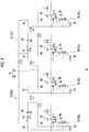
- the flow of a refrigerant in the connected state of the connection line 14 is shown in FIG. 3 by arrows.
- the P2 failure that is, a case in which a failure occurs in the circulation pump 26 of the second refrigerant circulation loop 12b is shown as an example. Accordingly, the circulation pump 26 of the first refrigerant circulation loop 12a is normally operated but the circulation pump 26 of the second refrigerant circulation loop 12b is not operated. As shown in FIG. 3 , the circulation pump 26 of the first refrigerant circulation loop 12a circulates a refrigerant in both the first refrigerant circulation loop 12a and the second refrigerant circulation loop 12b. A refrigerant is circulated in the first refrigerant circulation loop 12a as in the normal state.
- a refrigerant is supplied to the refrigerant supply line 50 of the second refrigerant circulation loop 12b from the refrigerant supply line 50 of the first refrigerant circulation loop 12a through the supply-side connection flow channel 56.
- the refrigerant is cooled by the heat exchangers (40 and 44) and the refrigerator stages (36 and 38), is supplied to the cooling-stage heat exchanger 48, and flows out to the refrigerant collection line 52.
- the refrigerant returns to the refrigerant collection line 52 of the first refrigerant circulation loop 12a from the refrigerant collection line 52 of the second refrigerant circulation loop 12b through the collection-side connection flow channel 58, and is collected to the circulation pump 26 of the first refrigerant circulation loop 12a. Since the on-off valves (V5 and V6) for backflow prevention of the second refrigerant circulation loop 12b are closed, the circulation of the backflow of a refrigerant in the second refrigerant circulation loop 12b in the connected state of the connection line 14 is prevented.
- the circulation pump 26 of the second refrigerant circulation loop 12b can circulate a refrigerant in both the first refrigerant circulation loop 12a and the second refrigerant circulation loop 12b.
- the cryogenic system 10 can cool the cryogenic cooling unit 20 by operating the plurality of refrigerant circulation loops 12 using the normal circulation pump 26 of the other refrigerant circulation loop 12. Even though a failure occurs in any circulation pump 26, the cooling operation of the cryogenic system 10 can be continued.
- the cryogenic system 10 includes the first refrigerant circulation loop 12a, the second refrigerant circulation loop 12b, and the connection line 14 that connects these two refrigerant circulation loops 12.
- the connection line 14 is adapted to be switchable to the connected state from the unconnected state.
- the first refrigerant circulation loop 12a and the second refrigerant circulation loop 12b are isolated from each other, the circulation pump 26 of the first refrigerant circulation loop 12a circulates a refrigerant in the first refrigerant circulation loop 12a, and the circulation pump 26 of the second refrigerant circulation loop 12b circulates a refrigerant in the second refrigerant circulation loop 12b.
- the first refrigerant circulation loop 12a and the second refrigerant circulation loop 12b are connected to each other through the connection line 14 and a refrigerant can be supplied to the second refrigerant circulation loop 12b from the first refrigerant circulation loop 12a or to the second refrigerant circulation loop 12b from the first refrigerant circulation loop 12a.
- connection line 14 The connected state of the connection line 14 is selected in a case in which a failure occurs in any circulation pump 26, so that the cooling of the cryogenic system 10 can be continued by the other normal circulation pump 26.
- the refrigerator 28 is not limited to a two-stage Stirling refrigerator, and may be another two-stage mechanical refrigerator, such as a two-stage GM refrigerator or a two-stage pulse tube refrigerator. Further, the refrigerator 28 may be a single-stage mechanical refrigerator, such as a single-stage Stirling refrigerator, a single-stage GM refrigerator, or a single-stage pulse tube refrigerator.
- the cryogenic system 10 can be expanded for various applications.
- the cryogenic system 10 includes two refrigerators 28 in the above-mentioned embodiment, but the cryogenic system 10 may include three or more refrigerators 28.
- each refrigerant circulation loop 12 is provided with one circulation pump 26 and one refrigerator 28 in the above-mentioned embodiment, but the invention is not limited thereto.
- At least one refrigerant circulation loop may include a plurality of refrigerant circulation sub-loops, each of which includes a mechanical refrigerator.
- the refrigerant circulation loop is provided with at least one circulation pump that is shared by the plurality of refrigerant circulation sub-loops.
- the plurality of refrigerant circulation sub-loops may be adapted to be capable of being individually isolated from the circulation pump.
- FIG. 4 is a diagram schematically showing another example of the cryogenic system 10 according to the embodiment.
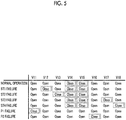
- FIG. 5 is a table illustrating a relationship between failure modes of the cryogenic system 10 shown in FIG. 4 and the state of a connection line 14.
- the cryogenic system 10 according to the embodiment exemplified in FIGS. 4 and 5 is common to the cryogenic system 10 exemplified in FIGS. 1 to 3 except that each of the refrigerant circulation loops 12 includes a plurality of refrigerant circulation sub-loops 70.
- each of the refrigerant circulation loops 12 includes a plurality of refrigerant circulation sub-loops 70.
- the cryogenic system 10 includes a first refrigerant circulation loop 12a and a second refrigerant circulation loop 12b.
- a connection line 14 connects the first refrigerant circulation loop 12a to the second refrigerant circulation loop 12b.
- Each of the refrigerant circulation loops 12 includes a plurality of refrigerant circulation sub-loops 70, that is, a first refrigerant circulation sub-loop 70a and a second refrigerant circulation sub-loop 70b.
- a circulation pump 26 of each refrigerant circulation loop 12 is shared by the plurality of refrigerant circulation sub-loops 70, and a refrigerant is supplied to both the first refrigerant circulation sub-loop 70a and the second refrigerant circulation sub-loop 70b from the common circulation pump 26. Further, the common circulation pump 26 collects a refrigerant from both the first refrigerant circulation sub-loop 70a and the second refrigerant circulation sub-loop 70b.
- the cryogenic system 10 includes a total of four refrigerators 28.
- Each of the refrigerators 28 is a single-stage Stirling refrigerator.
- Cryogenic cooling units 20 include a plurality of cooling stages, and each of the cooling stages is cooled by the corresponding refrigerant circulation sub-loop 70.
- Each refrigerator 28 includes a first-stage refrigerator stage 36.
- Each of the refrigerant circulation sub-loops 70 includes a first heat exchanger 40, a first-stage cooling unit 42, a cooling-stage heat exchanger 48, a refrigerant supply line 50, and a refrigerant collection line 52.
- the cryogenic system 10 includes eight on-off valves (V11 to V18).
- the open/closed states of the on-off valves (V11 to V18) in each failure mode are shown in FIG. 5 .
- the on-off valves (V14 and V15) are on-off valves for connection, and the on-off valves (V11 and V16) are on-off valves for backflow prevention.
- the remaining on-off valves (V12, V13, V17, and V18) are provided to individually isolate the refrigerant circulation sub-loops 70 from the refrigerant circulation loops 12.
- the on-off valves (V12 and V13) are disposed between the circulation pump 26 and the supply-side flow channel of the first heat exchanger 40, and the on-off valves (V17 and V18) are disposed between the circulation pump 26 and the supply-side flow channel of the first heat exchanger 40.
- the on-off valve V12 is provided on the first refrigerant circulation sub-loop 70a of the first refrigerant circulation loop 12a, and is closed in a case in which a failure occurs in the refrigerator 28 of the first refrigerant circulation sub-loop 70a ("ST1 failure" of FIG. 5 ). In this case, since the other on-off valves (V11 and V13) of the first refrigerant circulation loop 12a are opened, the circulation pump 26 of the first refrigerant circulation loop 12a can circulate a refrigerant in the second refrigerant circulation sub-loop 70b of the first refrigerant circulation loop 12a.
- the on-off valve V13 is provided on the second refrigerant circulation sub-loop 70b of the first refrigerant circulation loop 12a, and is closed in a case in which a failure occurs in the refrigerator 28 of the second refrigerant circulation sub-loop 70b ("ST2 failure" of FIG. 5 ).
- the on-off valve V17 is provided on the first refrigerant circulation sub-loop 70a of the second refrigerant circulation loop 12b, and is closed in a case in which a failure occurs in the refrigerator 28 of the first refrigerant circulation sub-loop 70a ("ST3 failure" of FIG. 5 ).
- the on-off valve V18 is provided on the second refrigerant circulation sub-loop 70b of the second refrigerant circulation loop 12b, and is closed in a case in which a failure occurs in the refrigerator 28 of the second refrigerant circulation sub-loop 70b ("ST4 failure" of FIG. 5 ) .
- connection line 14 The connected state of the connection line 14 is selected by the cryogenic system 10 shown in FIGS. 4 and 5 as well in a case in which a failure occurs in any circulation pump 26, so that the cooling of the cryogenic system 10 can be continued by the other normal circulation pump 26.
- the corresponding on-off valve (V12, V13, V17, or V18) is closed in a case in which a failure occurs in any refrigerator 28, so that the refrigerant circulation sub-loop 70 to which the refrigerator 28 belongs can be isolated from the cryogenic system 10.
- the supply-side refrigerant pipe 51 and the collection-side refrigerant pipe 53 are designed so that penetration heat generated due to the conduction of heat to the cryogenic cooling unit 20 from the refrigerator stage (for example, the first-stage refrigerator stage 36) caused by the failure of the refrigerator 28 can be substantially ignored.
- Thermal connection between the refrigerator 28 in which a failure occurs and the cryogenic cooling unit 20 is limited by a combination of such a design of a low-temperature-section refrigerant pipe and the on-off valves (V12, V13, V17, and V18). The penetration of heat into the cryogenic cooling unit 20 from the refrigerator 28 in which a failure occurs can be suppressed.
- FIG. 6 is a diagram schematically showing another example of the cryogenic system 10 according to the embodiment.
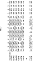
- FIG. 7 is a table illustrating a relationship between failure modes of the cryogenic system 10 shown in FIG. 6 and the state of a connection line 14.
- the states of circulation pumps 26 (P1 to P4) of the respective refrigerant circulation loops 12 are also shown in FIG. 7 .
- the cryogenic system 10 according to the embodiment exemplified in FIGS. 6 and 7 is common to the cryogenic system 10 exemplified in FIGS. 1 to 3 except that the cryogenic system 10 includes four refrigerant circulation loops 12.
- the cryogenic systems 10 according to the embodiments will be mainly described and common configuration will be briefly described or the description thereof will be omitted.
- the cryogenic system 10 includes a first refrigerant circulation loop 12a, a second refrigerant circulation loop 12b, a third refrigerant circulation loop 12c, and a fourth refrigerant circulation loop 12d.
- Each refrigerant circulation loop 12 is provided with one circulation pump 26 and one refrigerator 28.
- the refrigerator 28 is a single-stage Stirling refrigerator.
- the cryogenic system 10 includes a first connection line 14a that connects the first refrigerant circulation loop 12a to the second refrigerant circulation loop 12b, a second connection line 14b that connects the second refrigerant circulation loop 12b to the third refrigerant circulation loop 12c, and a third connection line 14c that connects the third refrigerant circulation loop 12c to the fourth refrigerant circulation loop 12d.
- the cryogenic system 10 includes ten on-off valves (V21 to V30).
- the on-off valves (V22 and V23) for connection are provided on the first connection line 14a
- the on-off valves (V25 and V26) for connection are provided on the second connection line 14b
- the on-off valves (V28 and V29) for connection are provided on the third connection line 14c.
- the remaining four on-off valves (V21, V24, V27, and V30) are on-off valves for backflow prevention of the first refrigerant circulation loop 12a, the second refrigerant circulation loop 12b, the third refrigerant circulation loop 12c, and the fourth refrigerant circulation loop 12d, respectively.
- the open/closed states of the on-off valves (V21 to V30) in each failure mode are shown in FIG. 7 .
- connection line 14 is selected by the cryogenic system 10 shown in FIGS. 6 and 7 as well in a case in which a failure occurs in any circulation pump 26, so that the cooling of the cryogenic system 10 can be continued by the other normal circulation pumps 26.
- the first connection line 14a is in a connected state (that is, the on-off valves (V22 and V23) for connection are opened) and a refrigerant can be circulated to the first refrigerant circulation loop 12a from the second refrigerant circulation loop 12b.
- the first connection line 14a is in a connected state (that is, the on-off valves (V22 and V23) for connection are opened) and a refrigerant can be circulated to the second refrigerant circulation loop 12b from the first refrigerant circulation loop 12a.
- the second connection line 14b is in a connected state (that is, the on-off valves (V25 and V26) for connection are opened) and a refrigerant can also be circulated to the second refrigerant circulation loop 12b from the third refrigerant circulation loop 12c.
- connection line 14 The connected state of the connection line 14 is selected by the cryogenic system 10 shown in FIGS. 6 and 7 as well in a case in which a failure occurs in any circulation pump 26, so that the cooling of the cryogenic system 10 can be continued by the other normal circulation pumps 26. Further, a refrigerator 28 in which a failure occurs can be thermally isolated from the cryogenic system 10 and the penetration of heat into the cryogenic cooling unit 20 from the refrigerator 28 in which a failure occurs can be suppressed by a combination of a low-temperature-section refrigerant pipe and the circulation pumps 26.
Landscapes
- Engineering & Computer Science (AREA)
- Physics & Mathematics (AREA)
- Mechanical Engineering (AREA)
- Thermal Sciences (AREA)
- General Engineering & Computer Science (AREA)
- Chemical & Material Sciences (AREA)
- Combustion & Propulsion (AREA)
Abstract
Description
- Certain embodiments of the present invention relate to a cryogenic system.
- Priority is claimed to Japanese Patent Application No.
2017-207999, filed October 27, 2017 - In the past, cryogenic coolers have been used to cool various objects to be cooled to a desired very low temperature. As cryogenic coolers, there are a cooler that directly cools an object to be cooled by a mechanical refrigerator, such as a GM refrigerator, a Stirling refrigerator, or a pulse tube refrigerator, a cooler that cools a refrigerant by such a mechanical refrigerator and cools an object to be cooled by a refrigerant, and the like.
- An example of the related art includes Japanese Unexamined Patent Application Publication No.
2016-211795 - A plurality of individual refrigerant circulation paths between which a refrigerant cannot be circulated are formed in a refrigerant cooling type cryogenic cooler. The cryogenic cooler includes a plurality of mechanical refrigerators, and the refrigerator is installed on each refrigerant circulation path to cool a refrigerant that is circulated in each refrigerant circulation path. In a case in which a function to cool a certain refrigerant circulation path is lost due to the failure of any one of the refrigerators or other reasons, the cooling capacity of the refrigerant circulation path is lost. In addition, since the refrigerator is a structure that connects a high-temperature section (for example, a room-temperature section) to a low-temperature section (for example, an object to be cooled), a refrigerator, which is stopped due to a failure or the like, forms a heat transfer path to the low-temperature section from the high-temperature section. For this reason, the refrigerator causes an increase in the penetration of heat into the object to be cooled. In this case, the cryogenic cooler cannot continue to perform desired cryogenic cooling or it may be difficult for the cryogenic cooler to perform desired cryogenic cooling.
- An exemplary object of an aspect of the invention is to improve the continuity of the cooling operation of a cryogenic system.
- According to an aspect of the invention, a cryogenic system includes a cryogenic cooling unit, a plurality of refrigerant circulation loops which are adapted to cool the cryogenic cooling unit by heat exchange between the cryogenic cooling unit and a refrigerant and each of which includes a circulation pump circulating the refrigerant and a mechanical refrigerator cooling the refrigerant, and a connection line that connects the plurality of refrigerant circulation loops to allow the refrigerant to be circulated. The connection line is adapted to be switchable to a connected state from an unconnected state, isolates the plurality of refrigerant circulation loops from each other in the unconnected state so that the circulation pump of each refrigerant circulation loop circulates the refrigerant in the refrigerant circulation loop, and connects the plurality of refrigerant circulation loops in the connected state so that the circulation pump of at least one refrigerant circulation loop circulates the refrigerant in at least one of the other refrigerant circulation loops as well.
- Embodiments in which any combination of the above-mentioned components and the components or expressions of the invention are substituted between a method, a device, a system, and the like are also effective as aspects of the invention.
- According to the invention, the continuity of the cooling operation of a cryogenic system can be improved.
-
-
FIG. 1 is a diagram schematically showing a cryogenic system according to an embodiment. -
FIG. 2 is a table illustrating a relationship between failure modes of the cryogenic system according to the embodiment and the state of a connection line. -
FIG. 3 is a diagram schematically showing the cryogenic system according to the embodiment. -
FIG. 4 is a diagram schematically showing another example of the cryogenic system according to the embodiment. -
FIG. 5 is a table illustrating a relationship between failure modes of the cryogenic system shown inFIG. 4 and the state of a connection line. -
FIG. 6 is a diagram schematically showing another example of the cryogenic system according to the embodiment. -
FIG. 7 is a table illustrating a relationship between failure modes of the cryogenic system shown inFIG. 6 and the state of a connection line. - An embodiment of the invention will be described in detail below with reference to the drawings. The same or equivalent components, members, and processing in the description and the drawings are denoted by the same reference numerals and the repeated description thereof will be appropriately omitted. The scale and shape of each part to be shown are conveniently set to facilitate description, and is not interpreted in a limited way as long as not particularly mentioned. The embodiment is exemplary, and does not limit the scope of the invention at all. All the characteristics to be described in the embodiment or combinations thereof are not necessarily essential in the invention.
-
FIG. 1 is a diagram schematically showing acryogenic system 10 according to an embodiment. Thecryogenic system 10 includes a plurality ofrefrigerant circulation loops 12, aconnection line 14, avacuum vessel 16, and acryogenic cooling unit 20 that cools anobject 18 to be cooled. A radiation shield, which is used to suppress the incidence of radiant heat on theobject 18 to be cooled and thecryogenic cooling unit 20, is usually installed in thevacuum vessel 16, but is not shown for simplification. - The
refrigerant circulation loops 12 are adapted to cool thecryogenic cooling unit 20 by heat exchange between thecryogenic cooling unit 20 and a refrigerant. The refrigerant is, for example, a refrigerant gas (for example, helium) . Each of the plurality ofrefrigerant circulation loops 12 circulates the refrigerant. Theconnection line 14 connects the plurality ofrefrigerant circulation loops 12 so that the refrigerant can be circulated. The exemplary structures of therefrigerant circulation loops 12 and theconnection line 14 will be described later. - The
vacuum vessel 16 is a cryogenic vacuum vessel, such as a cryostat, and partitions thecryogenic system 10 into a normal-temperature section 22 and a low-temperature section 24. That is, the normal-temperature section 22 of thecryogenic system 10 is disposed outside thevacuum vessel 16, and the low-temperature section 24 of thecryogenic system 10 is disposed in thevacuum vessel 16. The normal-temperature section 22 takes, for example, a room temperature or a temperature of about 300K. - For example, the
object 18 to be cooled is a detection element that detects infrared rays, submillimeter waves, X-rays, or other electromagnetic waves, and such a detection element is a component of an observation device that is used for astronomical observation. Theobject 18 to be cooled is in physical contact with thecryogenic cooling unit 20 and is thermally coupled to thecryogenic cooling unit 20, or is thermally coupled to thecryogenic cooling unit 20 through a heat transfer member. - The
cryogenic cooling unit 20 is also called a cooling stage. As shown inFIG. 1 , thecryogenic system 10 may include one common cooling stage as thecryogenic cooling unit 20. Alternatively, thecryogenic cooling unit 20 may include a plurality of cooling stages. In this case, each of therefrigerant circulation loops 12 may be provided with the cooling stage (for example, seeFIG. 4 ) . - The
cryogenic system 10 is adapted to be capable of being mounted on, for example, a spacecraft, such as an artificial satellite, together with theobject 18 to be cooled. Thecryogenic system 10 may be mounted on a ground facility including theobject 18 to be cooled. Thecryogenic system 10 may be mounted on a spacecraft or a ground facility together with, for example, a superconducting device orother objects 18 to be cooled for which a cryogenic environment is desirable. - The
refrigerant circulation loops 12 include a firstrefrigerant circulation loop 12a and a secondrefrigerant circulation loop 12b. Since theserefrigerant circulation loops 12 have the same configuration, the configuration of the firstrefrigerant circulation loop 12a will be mainly described below and the description of the secondrefrigerant circulation loop 12b will be appropriately omitted. - The first
refrigerant circulation loop 12a includes acirculation pump 26 that circulates a refrigerant and a mechanical refrigerator (hereinafter, simply referred to as a refrigerator) 28 that cools the refrigerant. - The
circulation pump 26 is adapted to increase the pressure of a refrigerant gas, which is collected from, for example, the low-temperature section 24, to, for example, about the atmospheric pressure or about several atmospheres. Thecirculation pump 26 can recover a pressure loss that occurs on the refrigerant in therefrigerant circulation loop 12. Thecirculation pump 26 may be a pump of which the output is lower than the output of acompressor 30 to be described later (for example, by about several W) . Thecirculation pump 26 is disposed in the normal-temperature section 22 of thecryogenic system 10. - For example, the
refrigerator 28 is a two-stage Stirling refrigerator. Therefrigerator 28 includes acompressor 30, a two-stagecold head 32 as an expander, and a connectingpipe 34 that connects thecompressor 30 to the two-stagecold head 32. The connectingpipe 34 provides a gas flow channel that circulates a refrigerant gas (for example, a helium gas) between thecompressor 30 and the two-stagecold head 32. The two-stagecold head 32 includes a first-stage refrigerator stage 36 and a second-stage refrigerator stage 38. The normal-temperature section 22 of thecryogenic system 10 includes thecompressor 30, a room-temperature portion of the two-stagecold head 32, and the connectingpipe 34, and the low-temperature section 24 of thecryogenic system 10 includes the first-stage refrigerator stage 36 and the second-stage refrigerator stage 38. - The
compressor 30 is adapted to generate the pressure oscillation of a refrigerant gas. The generated pressure oscillation is transmitted to the two-stage cold head 32 through the connectingpipe 34. The two-stage cold head 32 is adapted to induce pressure oscillation where the pressure oscillation transmitted from thecompressor 30 has a phase difference at the same frequency as the pressure oscillation in the two-stage cold head 32. Accordingly, a refrigeration cycle (specifically, reverse Stirling cycle) is formed between thecompressor 30 and the two-stage cold head 32. - In this way, the first-
stage refrigerator stage 36 of therefrigerator 28 is cooled to a first-stage cooling temperature and the second-stage refrigerator stage 38 is cooled to a second-stage cooling temperature. The first-stage cooling temperature of therefrigerator 28 is selected from the temperature range of, for example, 50K to 150K. The first-stage cooling temperature maybe in the temperature range of, for example, 80K to 120K. The second-stage cooling temperature is lower than the first-stage cooling temperature. The second-stage cooling temperature is selected from the temperature range of, for example, 4K to 25K. The second-stage cooling temperature may be in the temperature range of, for example, 10K to 20K. The second-stage cooling temperature may be lower than 4K (for example, in the range of 1K to 4K). - The first
refrigerant circulation loop 12a further includes afirst heat exchanger 40, a first-stage cooling unit 42, asecond heat exchanger 44, a second-stage cooling unit 46, and a cooling-stage heat exchanger 48. Thefirst heat exchanger 40, the first-stage cooling unit 42, thesecond heat exchanger 44, the second-stage cooling unit 46, and the cooling-stage heat exchanger 48 are disposed in thevacuum vessel 16, that is, in the low-temperature section 24 of thecryogenic system 10. - Further, for the connection of these components, the first
refrigerant circulation loop 12a further includes arefrigerant supply line 50 and arefrigerant collection line 52. Therefrigerant supply line 50 connects the discharge side of thecirculation pump 26 to the supply side of the cooling-stage heat exchanger 48, and therefrigerant collection line 52 connects the collection side of the cooling-stage heat exchanger 48 to the suction side of thecirculation pump 26. Accordingly, a part of each of therefrigerant supply line 50 and therefrigerant collection line 52 is disposed in the normal-temperature section 22, and the remaining part thereof is disposed in the low-temperature section 24. - The
refrigerant supply line 50 includes a supply-side refrigerant pipe 51 in the low-temperature section 24, and therefrigerant collection line 52 includes a collection-side refrigerant pipe 53 in the low-temperature section 24 (for example, pipes surrounded inFIG. 1 by a broken line) . The supply-side refrigerant pipe 51 connects the second-stage cooling unit 46 to the cooling-stage heat exchanger 48, and the collection-side refrigerant pipe 53 connects the cooling-stage heat exchanger 48 to a collection-side flow channel of thesecond heat exchanger 44. A refrigerant is supplied to the cooling-stage heat exchanger 48 from the second-stage cooling unit 46 through the supply-side refrigerant pipe 51, and the refrigerant is collected to thesecond heat exchanger 44 from the cooling-stage heat exchanger 48 through the collection-side refrigerant pipe 53. - The
first heat exchanger 40 cools a high-temperature (for example, a normal temperature, for example, about 300K) refrigerant gas that flows into thevacuum vessel 16 from thecirculation pump 26. Thesecond heat exchanger 44 further cools the refrigerant that is cooled by thefirst heat exchanger 40 and the first-stage cooling unit 42. - Each of the first and
second heat exchangers refrigerant supply line 50 includes a supply-side flow channel of each of the first andsecond heat exchangers refrigerant collection line 52 includes a collection-side flow channel of each of the first andsecond heat exchangers - The first-
stage cooling unit 42 is thermally coupled to the first-stage refrigerator stage 36. A refrigerant, which flows through the first-stage cooling unit 42, is cooled by heat exchange with the first-stage refrigerator stage 36. The first-stage cooling unit 42 is disposed on therefrigerant supply line 50 between the first andsecond heat exchangers - The second-
stage cooling unit 46 is thermally coupled to the second-stage refrigerator stage 38. A refrigerant, which flows through the second-stage cooling unit 46, is cooled by the second-stage refrigerator stage 38. The second-stage cooling unit 46 is disposed on therefrigerant supply line 50 between thesecond heat exchanger 44 and the cooling-stage heat exchanger 48. - The cooling-
stage heat exchanger 48 is thermally coupled to thecryogenic cooling unit 20. A refrigerant, which flows through the cooling-stage heat exchanger 48, cools thecryogenic cooling unit 20. - Likewise, the second
refrigerant circulation loop 12b includes acirculation pump 26 and arefrigerator 28. Therefrigerator 28 includes acompressor 30, a two-stage cold head 32, and a connectingpipe 34. The two-stage cold head 32 includes a first-stage refrigerator stage 36 and a second-stage refrigerator stage 38. Further, the secondrefrigerant circulation loop 12b includes afirst heat exchanger 40, a first-stage cooling unit 42, asecond heat exchanger 44, a second-stage cooling unit 46, a cooling-stage heat exchanger 48, arefrigerant supply line 50, and arefrigerant collection line 52. - The first
refrigerant circulation loop 12a includes abackflow prevention unit 54. Thebackflow prevention unit 54 includes a pair of on-off valves (V1 andV2) for backflow prevention. One on-off valve V1 for backflow prevention is provided on therefrigerant collection line 52, and the other on-off valve V2 for backflow prevention is provided on therefrigerant supply line 50. The on-off valves (V1 and V2) for backflow prevention are opened in an unconnected state of theconnection line 14. The on-off valves (V1 and V2) for backflow prevention are closed in a connected state of theconnection line 14. The details of the unconnected state and the connected state of theconnection line 14 will be described later. - In the example shown in
FIG. 1 , two on-off valves (V1 and V2) for backflow prevention are provided on the upstream side and the downstream side of thecirculation pump 26, respectively. However, only one on-off valve for backflow prevention may be provided, and any one of the on-off valves (V1 and V2) for backflow prevention may be provided in this case. - Likewise, the second
refrigerant circulation loop 12b also includes abackflow prevention unit 54. On-off valves for backflow prevention of the secondrefrigerant circulation loop 12b are denoted by V5 and V6 for convenience so as to be distinguished from the on-off valves (V1 and V2) for backflow prevention of the firstrefrigerant circulation loop 12a. Only one on-off valve for backflow prevention may be provided on the secondrefrigerant circulation loop 12b as well, and any one of the on-off valves (V5 and V6) for backflow prevention may be provided in this case. - The circulation of the backflow of a refrigerant in each
refrigerant circulation loop 12 can be prevented by a relatively simple structure of closing the on-off valves (V1, V2, V5, and V6) for backflow prevention. - The
backflow prevention units 54 are disposed in the normal-temperature section 22 of thecryogenic system 10. For this reason, a general-purpose component of which the operational reliability is ensured under a normal temperature can be employed as thebackflow prevention unit 54. Such a general-purpose component can be available at a lower cost than a component of which the reliability in a cryogenic environment is ensured. Thebackflow prevention units 54 may be disposed in the low-temperature section 24 of thecryogenic system 10, if possible. - The
connection line 14 is adapted to be switchable to the connected state from the unconnected state. Theconnection line 14 isolates the plurality ofrefrigerant circulation loops 12 from each other in the unconnected state so that thecirculation pump 26 of eachrefrigerant circulation loop 12 circulates a refrigerant in therefrigerant circulation loop 12. On the other hand, theconnection line 14 connects the plurality ofrefrigerant circulation loops 12 in the connected state so that thecirculation pump 26 of at least onerefrigerant circulation loop 12 circulates a refrigerant in at least one of the otherrefrigerant circulation loops 12 as well. Theconnection line 14 can also return to the unconnected state from the connected state. - The
connection line 14 includes connection flow channels that connect the tworefrigerant circulation loops 12 and on-off valves (V3 and V4) for connection that are provided on the connection flow channels, are closed in the unconnected state, and are opened in the connected state. The connected state and the unconnected state of theconnection line 14 can be switched by a relatively simple structure of opening and closing the on-off valves (V3 and V4) for connection. - More specifically, the
connection line 14 includes a supply-sideconnection flow channel 56 that connects therefrigerant supply lines 50 of the tworefrigerant circulation loops 12 and a supply-side on-off valve V3 for connection that is provided on the supply-sideconnection flow channel 56. Further, theconnection line 14 includes a collection-sideconnection flow channel 58 that connects therefrigerant collection lines 52 of the tworefrigerant circulation loops 12 and a collection-side on-off valve V4 for connection that is provided on the collection-sideconnection flow channel 58. Both the supply-side on-off valve V3 for connection and the collection-side on-off valve V4 for connection are closed in the unconnected state, and are opened in the connected state. - A supply-
side junction 60 between therefrigerant supply line 50 and the supply-sideconnection flow channel 56 is disposed between the on-off valve V2 for backflow prevention and the supply-side flow channel of thefirst heat exchanger 40. Accordingly, the on-off valve V2 for backflow prevention is disposed between the discharge side of thecirculation pump 26 and the supply-side junction 60. Further, a collection-side junction 62 between therefrigerant collection line 52 and the collection-sideconnection flow channel 58 is disposed between the on-off valve V1 for backflow prevention and the collection-side flow channel of thefirst heat exchanger 40. Accordingly, the on-off valve V1 for backflow prevention is disposed between the suction side of thecirculation pump 26 and the collection-side junction 62. - The
connection line 14 is disposed in the normal-temperature section 22 of thecryogenic system 10. Accordingly, general-purpose components of which the operational reliability is ensured under a normal temperature can be employed as the on-off valves (V3 and V4) for connection or the other components of theconnection line 14. Such a general-purpose component can be available at a lower cost than a component of which the reliability in a cryogenic environment is ensured. Theconnection line 14 may be disposed in the low-temperature section 24 of thecryogenic system 10, if possible. - In a case in which the respective on-off valves (V1 to V6) provided on the
refrigerant circulation loops 12 and theconnection line 14 are opened, a refrigerant can flow through the on-off valves. However, in a case in which the respective on-off valves (V1 to V6) are closed, a refrigerant cannot flow through the on-off valves. The respective on-off valves (V1 to V6) may be electromagnetic on-off valves, mechanical on-off valves, manual on-off valves, or other driven-type on-off valves . -
FIG. 2 is a table illustrating a relationship between failure modes of thecryogenic system 10 according to the embodiment and the state of theconnection line 14. The open/closed states of the respective on-off valves (V1 to V6) of theconnection line 14 are shown so as to correspond to some failure modes. In the table, "open" represents that the on-off valve is opened and "close" represents that the on-off valve is closed. - A normal operation and four failure modes of the
cryogenic system 10 are exemplified inFIG. 2 . "Normal operation" represents that all the circulation pumps 26 and therefrigerators 28 provided in thecryogenic system 10 are normally operated without a failure . "ST1 failure" represents that a failure occurs in therefrigerator 28 of the firstrefrigerant circulation loop 12a, and "ST2 failure" represents that a failure occurs in therefrigerator 28 of the secondrefrigerant circulation loop 12b. "P1 failure" represents that a failure occurs in thecirculation pump 26 of the firstrefrigerant circulation loop 12a, and "P2 failure" represents that a failure occurs in thecirculation pump 26 of the secondrefrigerant circulation loop 12b. - Since a
temperature sensor 64, which measures the temperature of the refrigerator stage, is usually installed on at least one of the first-stage refrigerator stage 36 and the second-stage refrigerator stage 38, it is possible to determine whether or not a failure occurs in therefrigerator 28 from the measurement result of thetemperature sensor 64. Since arefrigerant sensor 66, such as a pressure sensor for measuring the pressure of a refrigerant (and/or a flow sensor for measuring the flow rate of a refrigerant), is usually installed on therefrigerant circulation loop 12, it is possible to determine whether or not a failure occurs in thecirculation pump 26 from the measurement result of therefrigerant sensor 66. - As shown in the column of "normal operation" in
FIG. 2 , in a case in which thecryogenic system 10 is normally operated without a failure or abnormality, all the on-off valves (V1, V2, V5, and V6) for backflow prevention are opened and the both the supply-side on-off valve V3 for connection and the collection-side on-off valve V4 for connection are closed. This state is the unconnected state of theconnection line 14. The supply-side on-off valve V3 for connection and the collection-side on-off valve V4 for connection are closed in the unconnected state. - Accordingly, in the unconnected state of the
connection line 14, as shown inFIG. 1 by arrows, thecirculation pump 26 of the firstrefrigerant circulation loop 12a circulates a refrigerant in the firstrefrigerant circulation loop 12a and thecirculation pump 26 of the secondrefrigerant circulation loop 12b circulates a refrigerant in the secondrefrigerant circulation loop 12b. A refrigerant does not flow in theconnection line 14, and is not circulated between the firstrefrigerant circulation loop 12a and the secondrefrigerant circulation loop 12b. In this way, the plurality ofrefrigerant circulation loops 12 are operated independently of each other. - In the normal operation of the
cryogenic system 10, a refrigerant, which is sent to therefrigerant supply line 50 from thecirculation pump 26 of eachrefrigerant circulation loop 12, flows into thevacuum vessel 16 and is supplied to the supply-side flow channel of thefirst heat exchanger 40 for the first time. The refrigerant, which flows through the supply-side flow channel of thefirst heat exchanger 40, is cooled by exchanging heat with a return refrigerant that flows through the collection-side flow channel of thefirst heat exchanger 40. The refrigerant, which is cooled by thefirst heat exchanger 40, flows into the first-stage cooling unit 42 through therefrigerant supply line 50. - The refrigerant is cooled in the first-
stage cooling unit 42 by the first-stage refrigerator stage 36, and is sent to the supply-side flow channel of thesecond heat exchanger 44. The refrigerant, which flows through the supply-side flow channel of thesecond heat exchanger 44, is cooled by exchanging heat with a return refrigerant that flows through the collection-side flow channel of thesecond heat exchanger 44. The refrigerant, which is cooled by thesecond heat exchanger 44, flows into the second-stage cooling unit 46 through therefrigerant supply line 50. - The refrigerant is cooled in the second-
stage cooling unit 46 by the second-stage refrigerator stage 38, and is supplied to the cooling-stage heat exchanger 48. Thecryogenic cooling unit 20 is cooled by heat exchange between the refrigerant, which flows through the cooling-stage heat exchanger 48, and thecryogenic cooling unit 20. Thecryogenic cooling unit 20 is cooled to, for example, the second-stage cooling temperature of therefrigerator 28. Accordingly, thecryogenic cooling unit 20 can cool theobject 18 to be cooled to the temperature range of the second-stage cooling temperature. - The refrigerant flows to the
refrigerant collection line 52 from the cooling-stage heat exchanger 48. The refrigerant flows through therefrigerant collection line 52 in the order of thesecond heat exchanger 44 and thefirst heat exchanger 40. The temperature of the return refrigerant rises while the return refrigerant cools the refrigerant, which flows through therefrigerant supply line 50, at each of the heat exchangers (44 and 40) as described above. The refrigerant, which returns to the normal temperature in this way, gets out of thevacuum vessel 16, is collected to thecirculation pump 26, and is sent again. In this way, the respectiverefrigerant circulation loops 12 are operated individually at the time of the normal operation and thecryogenic system 10 can cool thecryogenic cooling unit 20 and theobject 18 to be cooled. - As shown in
FIG. 2 , theconnection line 14 is in the unconnected state in the cases of the ST1 failure and the ST2 failure as well. However, in these cases, unlike in the case of the normal operation, a refrigerant does not need to be circulated in therefrigerant circulation loop 12 to which therefrigerator 28 in which a failure occurs belongs. Accordingly, the operation of thecirculation pump 26 of the firstrefrigerant circulation loop 12a is stopped in the case of the ST1 failure, and thecirculation pump 26 of the secondrefrigerant circulation loop 12b is stopped in the case of the ST2 failure. In this way, thecirculation pump 26 of therefrigerant circulation loop 12 to which therefrigerator 28 in which a failure occurs belongs is stopped, and thecirculation pump 26 of the otherrefrigerant circulation loop 12 continues to be operated. - In the cases of the ST1 failure and the ST2 failure, the
refrigerator 28 cannot be already cooled. Therefrigerator 28 becomes a heat transfer path for heat to be transferred to the refrigerator stage from the normal-temperature section 22. Therefrigerator 28 in which a failure occurs can also be said a heat penetration source. Heat penetrates due to the conduction of heat to the first-stage refrigerator stage 36 and the second-stage refrigerator stage 38 from the normal-temperature section 22 through structural members (for example, a cylinder, a displacer, and the like) of therefrigerator 28. As a result, the temperature of each of the first-stage refrigerator stage 36 and the second-stage refrigerator stage 38 gradually rises to a normal temperature. If thecryogenic cooling unit 20 is directly mounted on the refrigerator stage, the temperature of thecryogenic cooling unit 20 also rises together with the temperature of the refrigerator stage due to the failure of therefrigerator 28. Since the cooling capacity of thecryogenic system 10 is reduced, it may be also difficult to maintain the cooling of theobject 18 to be cooled. - However, in this embodiment, a heat transfer path for heat to be transferred to the
cryogenic cooling unit 20 from the refrigerator stage in the cases of the ST1 failure and the ST2 failure is limited to the supply-side refrigerant pipe 51 and the collection-side refrigerant pipe 53. Each of the supply-side refrigerant pipe 51 and the collection-side refrigerant pipe 53 is a thin pipe which is relatively long and of which the thickness of a wall is small. The amount of heat, which is transferred to thecryogenic cooling unit 20 from the first-stage refrigerator stage 36 and the second-stage refrigerator stage 38 through the supply-side refrigerant pipe 51 and the collection-side refrigerant pipe 53 by the conduction of heat, is limited. For this reason, since the temperature rise of thecryogenic cooling unit 20 is delayed even though a failure occurs in therefrigerator 28, the cooling of theobject 18 to be cooled can be continued to some extent. - Preferably, the supply-
side refrigerant pipe 51 and the collection-side refrigerant pipe 53 are designed to limit penetration heat that is generated due to the conduction of heat to thecryogenic cooling unit 20 from the refrigerator stage (for example, the second-stage refrigerator stage 38) caused by the failure of therefrigerator 28, or are designed so that the penetration heat can be substantially ignored. Thermal connection between therefrigerator 28 and thecryogenic cooling unit 20 is limited by a combination of such a design of a low-temperature-section refrigerant pipe and the stop of the operation of thecirculation pump 26. Further, since a refrigerant, which is cooled by therefrigerator 28, is supplied to thecryogenic cooling unit 20 by the operation of thecirculation pump 26 in the normal state of therefrigerator 28, the thermal connection between therefrigerator 28 and thecryogenic cooling unit 20 is maintained. In this way, the low-temperature-section refrigerant pipe and thecirculation pump 26 function as a so-called thermal switch. - There are various problems in a case in which a generally-known mechanical thermal switch is applied to the
cryogenic system 10. In a case in which the mechanical thermal switch is disposed in a cryogenic environment, operational reliability at a very low temperature or the generation of heat from a drive unit may become a problem. In a case in which the drive unit of the mechanical thermal switch is disposed under a normal temperature, the drive of a switch is transmitted from the drive unit through a transmission member but this transmission member becomes a heat transfer path. Accordingly, the mechanical thermal switch is not used in this embodiment. Further, a gas-gap type thermal switch suitable for a cryogenic environment is also already known. However, since this thermal switch can be operated only in a cryogenic range equal to or lower than 4K, the thermal switch cannot be used in a cryogenic range higher than 4K. - In contrast, the above-mentioned combination of the low-temperature-section refrigerant pipe and the
circulation pump 26 does not have disadvantages, which are caused by an existing thermal switch, at all or hardly has the disadvantages. Arefrigerator 28 in which a failure occurs can be easily thermally isolated from thecryogenic system 10 by the use of this combination. - At least one
refrigerant circulation loop 12 includes the low-temperature-section refrigerant pipe (the supply-side refrigerant pipe 51 and/or the collection-side refrigerant pipe 53) that is disposed in the low-temperature section 24 of thecryogenic system 10. The amount of heat per unit time to be transferred due to the conduction of heat to the refrigerator stage of therefrigerator 28 from the normal-temperature section 22 of thecryogenic system 10, which is supposed in a case in which therefrigerator 28 does not function, may be in the range of 1/100 to 1/1000 (for example, 1/400 to 1/500) of the amount of heat per unit time that is transferred due to the conduction of heat to thecryogenic cooling unit 20 from the refrigerator stage through the low-temperature-section refrigerant pipe. Here, the case in which therefrigerator 28 does not function means a state in which the operation of therefrigerator 28 is stopped due to a failure or the like and therefrigerator 28 does not perform cooling work. In this case, penetration heat, which is generated due to the conduction of heat to thecryogenic cooling unit 20 from the refrigerator stage caused by the failure of therefrigerator 28, can be substantially ignored. - As an example of the design of the low-temperature-section refrigerant pipe, the material, the length, and the cross-sectional area of the low-temperature-section refrigerant pipe may be designed so that the amount of heat per unit time to be transferred due to the conduction of heat to the refrigerator stage of the
refrigerator 28 from the normal-temperature section 22, which is supposed in a case in which the refrigerator does not function, is in the range of 1/100 to 1/1000 (for example, 1/400 to 1/500) of the amount of heat per unit time to be transferred due to the conduction of heat to thecryogenic cooling unit 20 from the refrigerator stage through the low-temperature-section refrigerant pipe. In this case, penetration heat, which is generated due to the conduction of heat to thecryogenic cooling unit 20 from the refrigerator stage caused by the failure of therefrigerator 28, can be substantially ignored. - The supply-
side refrigerant pipe 51 and thecollection-side refrigerant pipe 53 are made of, for example, a material that has a thermal conductivity lower than the thermal conductivity of the material of the refrigerator stage . Since the refrigerator stage is usually made of copper, each of the supply-side refrigerant pipe 51 and the collection-side refrigerant pipe 53 may be a pipe made of, for example, stainless steel. Each of the supply-side refrigerant pipe 51 and the collection-side refrigerant pipe 53 may be a flexible pipe. In this case, the transmission of vibration to thecryogenic cooling unit 20 from therefrigerator 28 can be suppressed. - Each of the supply-
side refrigerant pipe 51 and the collection-side refrigerant pipe 53 is relatively long and is longer than, for example, the length of therefrigerator 28 in an axial direction. The length of each of the supply-side refrigerant pipe 51 and the collection-side refrigerant pipe 53 may be 2 times or more, 5 times or more, or 10 times or more the length of therefrigerator 28 in the axial direction. Here, the length of therefrigerator 28 in the axial direction may be a distance between the surface of a wall of thevacuum vessel 16 on which therefrigerator 28 is mounted and the refrigerator stage (for example, the second-stage refrigerator stage 38) (in other words, a distance between the normal-temperature section 22 and the refrigerator stage) . In a case in which the cold head (for example, the two-stage cold head 32) includes a reciprocating member, such as a displacer, the axial direction of therefrigerator 28 corresponds to the reciprocating direction of the reciprocating member. The length of each of the supply-side refrigerant pipe 51 and the collection-side refrigerant pipe 53 may be 100 times or less the length of therefrigerator 28 in the axial direction. - Further, the cross-sectional area of each of the supply-
side refrigerant pipe 51 and the collection-side refrigerant pipe 53 is relatively small and is smaller than, for example, the cross-sectional area of therefrigerator 28. The cross-sectional area of each of the supply-side refrigerant pipe 51 and the collection-side refrigerant pipe 53 may be 1/2 or less, 1/5 or less, or 1/10 or less of the cross-sectional area of therefrigerator 28. Here, the cross-sectional area of the refrigerant pipe means a cross-sectional area perpendicular to the axial direction of the pipe, and is obtained from the inner diameter and the outer diameter of the refrigerant pipe. The cross-sectional area of therefrigerator 28 means a cross-sectional area perpendicular to the axial direction of therefrigerator 28. For example, the cross-sectional area of therefrigerator 28 may be the cross-sectional area of a cylinder member of the cold head (for example, the two-stage cold head 32). The cross-sectional area of the cylinder member is obtained from the inner diameter and the outer diameter of the cylinder member. Each of the supply-side refrigerant pipe 51 and the collection-side refrigerant pipe 53 may be a pipe of which the thickness of a wall is smaller than that of the cylinder member. The cross-sectional area of each of the supply-side refrigerant pipe 51 and the collection-side refrigerant pipe 53 may be 1/100 or more of the cross-sectional area of therefrigerator 28. - As shown in
FIG. 2 , in the case of the P1 failure, the on-off valves (V1 andV2) for backflow prevention of the firstrefrigerant circulation loop 12a to which thecirculation pump 26 in which a failure occurs belongs are closed and the supply-side on-off valve V3 for connection and the collection-side on-off valve V4 for connection are opened together. The on-off valves (V5 and V6) for backflow prevention of the secondrefrigerant circulation loop 12b to which anormal circulation pump 26 belongs are opened. Further, in the case of the P2 failure, the on-off valves (V5 and V6) for backflow prevention of the secondrefrigerant circulation loop 12b to which thecirculation pump 26 in which a failure occurs belongs are closed and the supply-side on-off valve V3 for connection and the collection-side on-off valve V4 for connection are opened together. The on-off valves (V1 and V2) for backflow prevention of the firstrefrigerant circulation loop 12a to which anormal circulation pump 26 belongs are opened. These states correspond to the connected state of theconnection line 14. In the connected state, the supply-side on-off valve V3 for connection and the collection-side on-off valve V4 for connection are opened. - The flow of a refrigerant in the connected state of the
connection line 14 is shown inFIG. 3 by arrows. The P2 failure, that is, a case in which a failure occurs in thecirculation pump 26 of the secondrefrigerant circulation loop 12b is shown as an example. Accordingly, thecirculation pump 26 of the firstrefrigerant circulation loop 12a is normally operated but thecirculation pump 26 of the secondrefrigerant circulation loop 12b is not operated. As shown inFIG. 3 , thecirculation pump 26 of the firstrefrigerant circulation loop 12a circulates a refrigerant in both the firstrefrigerant circulation loop 12a and the secondrefrigerant circulation loop 12b. A refrigerant is circulated in the firstrefrigerant circulation loop 12a as in the normal state. - In regard to the second
refrigerant circulation loop 12b, a refrigerant is supplied to therefrigerant supply line 50 of the secondrefrigerant circulation loop 12b from therefrigerant supply line 50 of the firstrefrigerant circulation loop 12a through the supply-sideconnection flow channel 56. The refrigerant is cooled by the heat exchangers (40 and 44) and the refrigerator stages (36 and 38), is supplied to the cooling-stage heat exchanger 48, and flows out to therefrigerant collection line 52. The refrigerant returns to therefrigerant collection line 52 of the firstrefrigerant circulation loop 12a from therefrigerant collection line 52 of the secondrefrigerant circulation loop 12b through the collection-sideconnection flow channel 58, and is collected to thecirculation pump 26 of the firstrefrigerant circulation loop 12a. Since the on-off valves (V5 and V6) for backflow prevention of the secondrefrigerant circulation loop 12b are closed, the circulation of the backflow of a refrigerant in the secondrefrigerant circulation loop 12b in the connected state of theconnection line 14 is prevented. - In the case of the P1 failure, the
circulation pump 26 of the secondrefrigerant circulation loop 12b can circulate a refrigerant in both the firstrefrigerant circulation loop 12a and the secondrefrigerant circulation loop 12b. - In this way, in a case in which a failure occurs in the
circulation pump 26 of a certainrefrigerant circulation loop 12, thecryogenic system 10 can cool thecryogenic cooling unit 20 by operating the plurality ofrefrigerant circulation loops 12 using thenormal circulation pump 26 of the otherrefrigerant circulation loop 12. Even though a failure occurs in anycirculation pump 26, the cooling operation of thecryogenic system 10 can be continued. - As described above, the
cryogenic system 10 according to this embodiment includes the firstrefrigerant circulation loop 12a, the secondrefrigerant circulation loop 12b, and theconnection line 14 that connects these tworefrigerant circulation loops 12. Theconnection line 14 is adapted to be switchable to the connected state from the unconnected state. - In the unconnected state, the first
refrigerant circulation loop 12a and the secondrefrigerant circulation loop 12b are isolated from each other, thecirculation pump 26 of the firstrefrigerant circulation loop 12a circulates a refrigerant in the firstrefrigerant circulation loop 12a, and thecirculation pump 26 of the secondrefrigerant circulation loop 12b circulates a refrigerant in the secondrefrigerant circulation loop 12b. In the connected state, the firstrefrigerant circulation loop 12a and the secondrefrigerant circulation loop 12b are connected to each other through theconnection line 14 and a refrigerant can be supplied to the secondrefrigerant circulation loop 12b from the firstrefrigerant circulation loop 12a or to the secondrefrigerant circulation loop 12b from the firstrefrigerant circulation loop 12a. - The connected state of the
connection line 14 is selected in a case in which a failure occurs in anycirculation pump 26, so that the cooling of thecryogenic system 10 can be continued by the othernormal circulation pump 26. Thecryogenic system 10, which has stable cooling performance for a longer time and uses a plurality ofrefrigerators 28, can be realized in this way. - The
refrigerator 28 is not limited to a two-stage Stirling refrigerator, and may be another two-stage mechanical refrigerator, such as a two-stage GM refrigerator or a two-stage pulse tube refrigerator. Further, therefrigerator 28 may be a single-stage mechanical refrigerator, such as a single-stage Stirling refrigerator, a single-stage GM refrigerator, or a single-stage pulse tube refrigerator. - The
cryogenic system 10 can be expanded for various applications. Thecryogenic system 10 includes tworefrigerators 28 in the above-mentioned embodiment, but thecryogenic system 10 may include three ormore refrigerators 28. - Further, each
refrigerant circulation loop 12 is provided with onecirculation pump 26 and onerefrigerator 28 in the above-mentioned embodiment, but the invention is not limited thereto. At least one refrigerant circulation loop may include a plurality of refrigerant circulation sub-loops, each of which includes a mechanical refrigerator. The refrigerant circulation loop is provided with at least one circulation pump that is shared by the plurality of refrigerant circulation sub-loops. The plurality of refrigerant circulation sub-loops may be adapted to be capable of being individually isolated from the circulation pump. -
FIG. 4 is a diagram schematically showing another example of thecryogenic system 10 according to the embodiment.FIG. 5 is a table illustrating a relationship between failure modes of thecryogenic system 10 shown inFIG. 4 and the state of aconnection line 14. - The
cryogenic system 10 according to the embodiment exemplified inFIGS. 4 and5 is common to thecryogenic system 10 exemplified inFIGS. 1 to 3 except that each of therefrigerant circulation loops 12 includes a plurality ofrefrigerant circulation sub-loops 70. Hereinafter, differences between thecryogenic systems 10 according to the embodiments will be mainly described and common configuration will be briefly described or the description thereof will be omitted. - The
cryogenic system 10 includes a firstrefrigerant circulation loop 12a and a secondrefrigerant circulation loop 12b. Aconnection line 14 connects the firstrefrigerant circulation loop 12a to the secondrefrigerant circulation loop 12b. Each of therefrigerant circulation loops 12 includes a plurality ofrefrigerant circulation sub-loops 70, that is, a first refrigerant circulation sub-loop 70a and a second refrigerant circulation sub-loop 70b. Acirculation pump 26 of eachrefrigerant circulation loop 12 is shared by the plurality ofrefrigerant circulation sub-loops 70, and a refrigerant is supplied to both the first refrigerant circulation sub-loop 70a and the second refrigerant circulation sub-loop 70b from thecommon circulation pump 26. Further, thecommon circulation pump 26 collects a refrigerant from both the first refrigerant circulation sub-loop 70a and the second refrigerant circulation sub-loop 70b. - The
cryogenic system 10 includes a total of fourrefrigerators 28. Each of therefrigerators 28 is a single-stage Stirling refrigerator.Cryogenic cooling units 20 include a plurality of cooling stages, and each of the cooling stages is cooled by the correspondingrefrigerant circulation sub-loop 70. Eachrefrigerator 28 includes a first-stage refrigerator stage 36. Each of therefrigerant circulation sub-loops 70 includes afirst heat exchanger 40, a first-stage cooling unit 42, a cooling-stage heat exchanger 48, arefrigerant supply line 50, and arefrigerant collection line 52. - The
cryogenic system 10 includes eight on-off valves (V11 to V18). The open/closed states of the on-off valves (V11 to V18) in each failure mode are shown inFIG. 5 . The on-off valves (V14 and V15) are on-off valves for connection, and the on-off valves (V11 and V16) are on-off valves for backflow prevention. - The remaining on-off valves (V12, V13, V17, and V18) are provided to individually isolate the refrigerant circulation sub-loops 70 from the
refrigerant circulation loops 12. The on-off valves (V12 and V13) are disposed between thecirculation pump 26 and the supply-side flow channel of thefirst heat exchanger 40, and the on-off valves (V17 and V18) are disposed between thecirculation pump 26 and the supply-side flow channel of thefirst heat exchanger 40. - The on-off valve V12 is provided on the first refrigerant circulation sub-loop 70a of the first
refrigerant circulation loop 12a, and is closed in a case in which a failure occurs in therefrigerator 28 of the first refrigerant circulation sub-loop 70a ("ST1 failure" ofFIG. 5 ). In this case, since the other on-off valves (V11 and V13) of the firstrefrigerant circulation loop 12a are opened, thecirculation pump 26 of the firstrefrigerant circulation loop 12a can circulate a refrigerant in the second refrigerant circulation sub-loop 70b of the firstrefrigerant circulation loop 12a. - Likewise, the on-off valve V13 is provided on the second refrigerant circulation sub-loop 70b of the first
refrigerant circulation loop 12a, and is closed in a case in which a failure occurs in therefrigerator 28 of the second refrigerant circulation sub-loop 70b ("ST2 failure" ofFIG. 5 ). The on-off valve V17 is provided on the first refrigerant circulation sub-loop 70a of the secondrefrigerant circulation loop 12b, and is closed in a case in which a failure occurs in therefrigerator 28 of the first refrigerant circulation sub-loop 70a ("ST3 failure" ofFIG. 5 ). The on-off valve V18 is provided on the second refrigerant circulation sub-loop 70b of the secondrefrigerant circulation loop 12b, and is closed in a case in which a failure occurs in therefrigerator 28 of the second refrigerant circulation sub-loop 70b ("ST4 failure" ofFIG. 5 ) . - The connected state of the
connection line 14 is selected by thecryogenic system 10 shown inFIGS. 4 and5 as well in a case in which a failure occurs in anycirculation pump 26, so that the cooling of thecryogenic system 10 can be continued by the othernormal circulation pump 26. - Further, the corresponding on-off valve (V12, V13, V17, or V18) is closed in a case in which a failure occurs in any
refrigerator 28, so that the refrigerant circulation sub-loop 70 to which therefrigerator 28 belongs can be isolated from thecryogenic system 10. - The supply-
side refrigerant pipe 51 and the collection-side refrigerant pipe 53 are designed so that penetration heat generated due to the conduction of heat to thecryogenic cooling unit 20 from the refrigerator stage (for example, the first-stage refrigerator stage 36) caused by the failure of therefrigerator 28 can be substantially ignored. Thermal connection between therefrigerator 28 in which a failure occurs and thecryogenic cooling unit 20 is limited by a combination of such a design of a low-temperature-section refrigerant pipe and the on-off valves (V12, V13, V17, and V18). The penetration of heat into thecryogenic cooling unit 20 from therefrigerator 28 in which a failure occurs can be suppressed. -
FIG. 6 is a diagram schematically showing another example of thecryogenic system 10 according to the embodiment.FIG. 7 is a table illustrating a relationship between failure modes of thecryogenic system 10 shown inFIG. 6 and the state of aconnection line 14. The states of circulation pumps 26 (P1 to P4) of the respectiverefrigerant circulation loops 12 are also shown inFIG. 7 . - The
cryogenic system 10 according to the embodiment exemplified inFIGS. 6 and7 is common to thecryogenic system 10 exemplified inFIGS. 1 to 3 except that thecryogenic system 10 includes fourrefrigerant circulation loops 12. Hereinafter, differences between thecryogenic systems 10 according to the embodiments will be mainly described and common configuration will be briefly described or the description thereof will be omitted. - The
cryogenic system 10 includes a firstrefrigerant circulation loop 12a, a secondrefrigerant circulation loop 12b, a thirdrefrigerant circulation loop 12c, and a fourthrefrigerant circulation loop 12d. Eachrefrigerant circulation loop 12 is provided with onecirculation pump 26 and onerefrigerator 28. Therefrigerator 28 is a single-stage Stirling refrigerator. Thecryogenic system 10 includes afirst connection line 14a that connects the firstrefrigerant circulation loop 12a to the secondrefrigerant circulation loop 12b, asecond connection line 14b that connects the secondrefrigerant circulation loop 12b to the thirdrefrigerant circulation loop 12c, and athird connection line 14c that connects the thirdrefrigerant circulation loop 12c to the fourthrefrigerant circulation loop 12d. - The
cryogenic system 10 includes ten on-off valves (V21 to V30). The on-off valves (V22 and V23) for connection are provided on thefirst connection line 14a, the on-off valves (V25 and V26) for connection are provided on thesecond connection line 14b, and the on-off valves (V28 and V29) for connection are provided on thethird connection line 14c. The remaining four on-off valves (V21, V24, V27, and V30) are on-off valves for backflow prevention of the firstrefrigerant circulation loop 12a, the secondrefrigerant circulation loop 12b, the thirdrefrigerant circulation loop 12c, and the fourthrefrigerant circulation loop 12d, respectively. The open/closed states of the on-off valves (V21 to V30) in each failure mode are shown inFIG. 7 . - The connected state of the
connection line 14 is selected by thecryogenic system 10 shown inFIGS. 6 and7 as well in a case in which a failure occurs in anycirculation pump 26, so that the cooling of thecryogenic system 10 can be continued by the other normal circulation pumps 26. For example, in a case in which a P1 failure occurs, thefirst connection line 14a is in a connected state (that is, the on-off valves (V22 and V23) for connection are opened) and a refrigerant can be circulated to the firstrefrigerant circulation loop 12a from the secondrefrigerant circulation loop 12b. In a case in which a P2 failure occurs, thefirst connection line 14a is in a connected state (that is, the on-off valves (V22 and V23) for connection are opened) and a refrigerant can be circulated to the secondrefrigerant circulation loop 12b from the firstrefrigerant circulation loop 12a. Alternatively, in a case in which a P2 failure occurs, thesecond connection line 14b is in a connected state (that is, the on-off valves (V25 and V26) for connection are opened) and a refrigerant can also be circulated to the secondrefrigerant circulation loop 12b from the thirdrefrigerant circulation loop 12c. - The connected state of the
connection line 14 is selected by thecryogenic system 10 shown inFIGS. 6 and7 as well in a case in which a failure occurs in anycirculation pump 26, so that the cooling of thecryogenic system 10 can be continued by the other normal circulation pumps 26. Further, arefrigerator 28 in which a failure occurs can be thermally isolated from thecryogenic system 10 and the penetration of heat into thecryogenic cooling unit 20 from therefrigerator 28 in which a failure occurs can be suppressed by a combination of a low-temperature-section refrigerant pipe and the circulation pumps 26. - The invention has been described above on the basis of the embodiments. Since the invention can include various design changes without being limited to the above-mentionedembodiments, it is understood by those skilled in the art that the invention can have various modification examples and the modification examples are also included in the scope of the invention.
-
- 10:
- cryogenic system
- 12:
- refrigerant circulation loop
- 12a:
- first refrigerant circulation loop
- 12b:
- second refrigerant circulation loop
- 14:
- connection line
- 20:
- cryogenic cooling unit
- 22:
- normal-temperature section
- 24:
- low-temperature section
- 26:
- circulation pump
- 28:
- refrigerator
- 54:
- backflow prevention unit
- 56:
- supply-side connection flow channel
- 58:
- collection-side connection flow channel
- 70:
- refrigerant circulation sub-loop
- 70a:
- first refrigerant circulation sub-loop
- 70b:
- second refrigerant circulation sub-loop
Claims (8)
- A cryogenic system comprising:a cryogenic cooling unit;a plurality of refrigerant circulation loops which are adapted to cool the cryogenic cooling unit by heat exchange between the cryogenic cooling unit and a refrigerant and each of which includes a circulation pump circulating the refrigerant and a mechanical refrigerator cooling the refrigerant; anda connection line that connects the plurality of refrigerant circulation loops to allow the refrigerant to be circulated,wherein the connection line is adapted to be switchable to a connected state from an unconnected state, isolates the plurality of refrigerant circulation loops from each other in the unconnected state so that the circulation pump of each refrigerant circulation loop circulates the refrigerant in the refrigerant circulation loop, and connects the plurality of refrigerant circulation loops in the connected state so that the circulation pump of at least one refrigerant circulation loop circulates the refrigerant in at least one of the other refrigerant circulation loops as well.
- The cryogenic system according to claim 1,wherein the connection line includes a connection flow channel that connects two refrigerant circulation loops and an on-off valve for connection that is provided on the connection flow channel, is closed in the unconnected state, and is opened in the connected state.
- The cryogenic system according to claim 1 or 2,wherein the connection line is disposed in a normal-temperature section of the cryogenic system.
- The cryogenic system according to any one of claims 1 to 3,wherein each refrigerant circulation loop includes a backflow prevention unit.
- The cryogenic system according to claim 4,wherein the backflow prevention unit includes an on-off valve for backflow prevention that is opened in the unconnected state and is closed in the connected state.
- The cryogenic system according to claim 4 or 5,wherein the backflow prevention unit is disposed in a normal-temperature section of the cryogenic system.
- The cryogenic system according to any one of claims 1 to 6,wherein at least one refrigerant circulation loop includes a plurality of refrigerant circulation sub-loops each of which includes the mechanical refrigerator, andthe plurality of refrigerant circulation sub-loops are capable of being individually isolated from the circulation pumps.
- The cryogenic system according to any one of claims 1 to 7,wherein at least one refrigerant circulation loop includes a low-temperature-section refrigerant pipe that is disposed in a low-temperature section of the cryogenic system, andthe amount of heat per unit time to be transferred due to conduction of heat to a refrigerator stage of the mechanical refrigerator from the normal-temperature section of the cryogenic system, which is supposed in a case in which the mechanical refrigerator does not function, is in a range of 1/100 to 1/1000 of the amount of heat per unit time to be transferred due to conduction of heat to the cryogenic cooling unit from the refrigerator stage through the low-temperature-section refrigerant pipe.
Applications Claiming Priority (1)
| Application Number | Priority Date | Filing Date | Title |
|---|---|---|---|
| JP2017207999A JP6975019B2 (en) | 2017-10-27 | 2017-10-27 | Cryogenic system |
Publications (2)
| Publication Number | Publication Date |
|---|---|
| EP3477223A1 true EP3477223A1 (en) | 2019-05-01 |
| EP3477223B1 EP3477223B1 (en) | 2020-07-22 |
Family
ID=63878491
Family Applications (1)
| Application Number | Title | Priority Date | Filing Date |
|---|---|---|---|
| EP18200885.4A Active EP3477223B1 (en) | 2017-10-27 | 2018-10-17 | Cryogenic system |
Country Status (2)
| Country | Link |
|---|---|
| EP (1) | EP3477223B1 (en) |
| JP (1) | JP6975019B2 (en) |
Cited By (6)
| Publication number | Priority date | Publication date | Assignee | Title |
|---|---|---|---|---|
| EP3865789A1 (en) * | 2020-02-17 | 2021-08-18 | Sumitomo Heavy Industries, Ltd. | Cryogenic system |
| IT202100003458A1 (en) * | 2021-02-16 | 2022-08-16 | Gran Sasso Science Inst | SYSTEM AND METHOD FOR VIBRATION REDUCTION IN PRESSURE SWING SYSTEMS |
| EP4350250A1 (en) * | 2022-10-07 | 2024-04-10 | Hamilton Sundstrand Corporation | Cryocooler with transient thermal storage |
| EP4367450A4 (en) * | 2021-07-08 | 2025-05-21 | Maybell Quantum Industries, Inc. | INTEGRATED DILUTION REFRIGERATORS |
| EP4474729A4 (en) * | 2022-01-31 | 2025-07-23 | Sumitomo Heavy Industries | CRYOGENIC COOLING DEVICE |
| EP4671643A1 (en) * | 2024-06-28 | 2025-12-31 | Bluefors Oy | CRYOGENS COOLING SYSTEM |
Families Citing this family (1)
| Publication number | Priority date | Publication date | Assignee | Title |
|---|---|---|---|---|
| JP2023156879A (en) * | 2022-04-13 | 2023-10-25 | 株式会社東芝 | Cryogenic cooling system, superconducting device, and operating method of cryogenic cooling system |
Citations (4)
| Publication number | Priority date | Publication date | Assignee | Title |
|---|---|---|---|---|
| US5889456A (en) * | 1997-05-16 | 1999-03-30 | Spectrospin Ag | NMR measuring device having a cooled probe head |
| US6679066B1 (en) * | 2002-08-16 | 2004-01-20 | Sumitomo Heavy Industries, Ltd. | Cryogenic cooling system for superconductive electric machines |
| EP1643197A2 (en) * | 2004-09-29 | 2006-04-05 | The Boc Group, Inc. | Backup cryogenic refrigeration system |
| JP2016211795A (en) | 2015-05-11 | 2016-12-15 | 株式会社東芝 | Cryogenic cooling device and cryogenic cooling method |
Family Cites Families (5)
| Publication number | Priority date | Publication date | Assignee | Title |
|---|---|---|---|---|
| US7266954B2 (en) * | 2002-12-16 | 2007-09-11 | Sumitomo Heavy Industries, Ltd | Method and device for installing refrigerator |
| US7003977B2 (en) * | 2003-07-18 | 2006-02-28 | General Electric Company | Cryogenic cooling system and method with cold storage device |
| JP2005201604A (en) * | 2004-01-19 | 2005-07-28 | Sumitomo Heavy Ind Ltd | Low temperature cooling system, and heat storage device |
| WO2011132231A1 (en) * | 2010-04-23 | 2011-10-27 | 住友重機械工業株式会社 | Cooling system and cooling method |
| US10508845B2 (en) * | 2015-06-02 | 2019-12-17 | Mitsubishi Electric Corporation | Refrigeration cycle system |
-
2017
- 2017-10-27 JP JP2017207999A patent/JP6975019B2/en active Active
-
2018
- 2018-10-17 EP EP18200885.4A patent/EP3477223B1/en active Active
Patent Citations (4)
| Publication number | Priority date | Publication date | Assignee | Title |
|---|---|---|---|---|
| US5889456A (en) * | 1997-05-16 | 1999-03-30 | Spectrospin Ag | NMR measuring device having a cooled probe head |
| US6679066B1 (en) * | 2002-08-16 | 2004-01-20 | Sumitomo Heavy Industries, Ltd. | Cryogenic cooling system for superconductive electric machines |
| EP1643197A2 (en) * | 2004-09-29 | 2006-04-05 | The Boc Group, Inc. | Backup cryogenic refrigeration system |
| JP2016211795A (en) | 2015-05-11 | 2016-12-15 | 株式会社東芝 | Cryogenic cooling device and cryogenic cooling method |
Cited By (7)
| Publication number | Priority date | Publication date | Assignee | Title |
|---|---|---|---|---|
| EP3865789A1 (en) * | 2020-02-17 | 2021-08-18 | Sumitomo Heavy Industries, Ltd. | Cryogenic system |
| IT202100003458A1 (en) * | 2021-02-16 | 2022-08-16 | Gran Sasso Science Inst | SYSTEM AND METHOD FOR VIBRATION REDUCTION IN PRESSURE SWING SYSTEMS |
| EP4367450A4 (en) * | 2021-07-08 | 2025-05-21 | Maybell Quantum Industries, Inc. | INTEGRATED DILUTION REFRIGERATORS |
| EP4474729A4 (en) * | 2022-01-31 | 2025-07-23 | Sumitomo Heavy Industries | CRYOGENIC COOLING DEVICE |
| EP4350250A1 (en) * | 2022-10-07 | 2024-04-10 | Hamilton Sundstrand Corporation | Cryocooler with transient thermal storage |
| US12455100B2 (en) | 2022-10-07 | 2025-10-28 | Hamilton Sundstrand Corporation | Cryocooler with transient thermal storage |
| EP4671643A1 (en) * | 2024-06-28 | 2025-12-31 | Bluefors Oy | CRYOGENS COOLING SYSTEM |
Also Published As
| Publication number | Publication date |
|---|---|
| EP3477223B1 (en) | 2020-07-22 |
| JP6975019B2 (en) | 2021-12-01 |
| JP2019078511A (en) | 2019-05-23 |
Similar Documents
| Publication | Publication Date | Title |
|---|---|---|
| EP3477223B1 (en) | Cryogenic system | |
| EP3477225B1 (en) | Cryogenic system | |
| US20110000228A1 (en) | Hybrid cryocooler with multiple passive stages | |
| JP3702964B2 (en) | Multistage low temperature refrigerator | |
| CN106062491B (en) | Hybrid Brayton-Gifford-McMahon Expander | |
| US20250277607A1 (en) | Joule-thomson cryocooler | |
| CN104428608B (en) | Vibration damping device for pulse tube refrigerators such as MRI systems | |
| WO2023203277A1 (en) | Cryostat, and method for cooling a cryostat | |
| JPH0781754B2 (en) | refrigerator | |
| CN101963410B (en) | Multi-path bypass type pulse tube refrigerating system | |
| EP1839000B1 (en) | Multi-stage cryocooler with concentric second stage | |
| US7305835B2 (en) | Pulse tube cooling by circulation of buffer gas | |
| EP3865789A1 (en) | Cryogenic system | |
| JP2022538133A (en) | Cryogenic coolers, especially for spacecraft radiation detectors | |
| JP2000220902A (en) | Cooling system | |
| Uhlig | Cryogen-free dilution refrigerator with separate 1K cooling circuit. | |
| US20170343246A1 (en) | Closed cycle cryogen recirculation system and method | |
| JP4472572B2 (en) | Cryogenic cooling device for cooling superconducting power storage device | |
| US7165406B2 (en) | Integral pulse tube refrigerator and cryopump | |
| WO2026047664A1 (en) | Cryostat incorporating high efficiency cryocooling system | |
| WO2023145302A1 (en) | Cryogenic cooling device |
Legal Events
| Date | Code | Title | Description |
|---|---|---|---|
| PUAI | Public reference made under article 153(3) epc to a published international application that has entered the european phase |
Free format text: ORIGINAL CODE: 0009012 |
|
| STAA | Information on the status of an ep patent application or granted ep patent |
Free format text: STATUS: REQUEST FOR EXAMINATION WAS MADE |
|
| 17P | Request for examination filed |
Effective date: 20181017 |
|
| AK | Designated contracting states |
Kind code of ref document: A1 Designated state(s): AL AT BE BG CH CY CZ DE DK EE ES FI FR GB GR HR HU IE IS IT LI LT LU LV MC MK MT NL NO PL PT RO RS SE SI SK SM TR |
|
| AX | Request for extension of the european patent |
Extension state: BA ME |
|
| STAA | Information on the status of an ep patent application or granted ep patent |
Free format text: STATUS: EXAMINATION IS IN PROGRESS |
|
| 17Q | First examination report despatched |
Effective date: 20190510 |
|
| GRAP | Despatch of communication of intention to grant a patent |
Free format text: ORIGINAL CODE: EPIDOSNIGR1 |
|
| STAA | Information on the status of an ep patent application or granted ep patent |
Free format text: STATUS: GRANT OF PATENT IS INTENDED |
|
| INTG | Intention to grant announced |
Effective date: 20191029 |
|
| GRAS | Grant fee paid |
Free format text: ORIGINAL CODE: EPIDOSNIGR3 |
|
| GRAJ | Information related to disapproval of communication of intention to grant by the applicant or resumption of examination proceedings by the epo deleted |
Free format text: ORIGINAL CODE: EPIDOSDIGR1 |
|
| GRAL | Information related to payment of fee for publishing/printing deleted |
Free format text: ORIGINAL CODE: EPIDOSDIGR3 |
|
| STAA | Information on the status of an ep patent application or granted ep patent |
Free format text: STATUS: EXAMINATION IS IN PROGRESS |
|
| INTC | Intention to grant announced (deleted) | ||
| GRAS | Grant fee paid |
Free format text: ORIGINAL CODE: EPIDOSNIGR3 |
|
| STAA | Information on the status of an ep patent application or granted ep patent |
Free format text: STATUS: GRANT OF PATENT IS INTENDED |
|
| GRAP | Despatch of communication of intention to grant a patent |
Free format text: ORIGINAL CODE: EPIDOSNIGR1 |
|
| INTG | Intention to grant announced |
Effective date: 20200512 |
|
| GRAA | (expected) grant |
Free format text: ORIGINAL CODE: 0009210 |
|
| STAA | Information on the status of an ep patent application or granted ep patent |
Free format text: STATUS: THE PATENT HAS BEEN GRANTED |
|
| AK | Designated contracting states |
Kind code of ref document: B1 Designated state(s): AL AT BE BG CH CY CZ DE DK EE ES FI FR GB GR HR HU IE IS IT LI LT LU LV MC MK MT NL NO PL PT RO RS SE SI SK SM TR |
|
| REG | Reference to a national code |
Ref country code: GB Ref legal event code: FG4D |
|
| REG | Reference to a national code |
Ref country code: CH Ref legal event code: EP |
|
| REG | Reference to a national code |
Ref country code: DE Ref legal event code: R096 Ref document number: 602018006218 Country of ref document: DE |
|
| REG | Reference to a national code |
Ref country code: AT Ref legal event code: REF Ref document number: 1293772 Country of ref document: AT Kind code of ref document: T Effective date: 20200815 |
|
| REG | Reference to a national code |
Ref country code: IE Ref legal event code: FG4D |
|
| REG | Reference to a national code |
Ref country code: LT Ref legal event code: MG4D |
|
| REG | Reference to a national code |
Ref country code: AT Ref legal event code: MK05 Ref document number: 1293772 Country of ref document: AT Kind code of ref document: T Effective date: 20200722 |
|
| PG25 | Lapsed in a contracting state [announced via postgrant information from national office to epo] |
Ref country code: ES Free format text: LAPSE BECAUSE OF FAILURE TO SUBMIT A TRANSLATION OF THE DESCRIPTION OR TO PAY THE FEE WITHIN THE PRESCRIBED TIME-LIMIT Effective date: 20200722 Ref country code: PT Free format text: LAPSE BECAUSE OF FAILURE TO SUBMIT A TRANSLATION OF THE DESCRIPTION OR TO PAY THE FEE WITHIN THE PRESCRIBED TIME-LIMIT Effective date: 20201123 Ref country code: LT Free format text: LAPSE BECAUSE OF FAILURE TO SUBMIT A TRANSLATION OF THE DESCRIPTION OR TO PAY THE FEE WITHIN THE PRESCRIBED TIME-LIMIT Effective date: 20200722 Ref country code: BG Free format text: LAPSE BECAUSE OF FAILURE TO SUBMIT A TRANSLATION OF THE DESCRIPTION OR TO PAY THE FEE WITHIN THE PRESCRIBED TIME-LIMIT Effective date: 20201022 Ref country code: SE Free format text: LAPSE BECAUSE OF FAILURE TO SUBMIT A TRANSLATION OF THE DESCRIPTION OR TO PAY THE FEE WITHIN THE PRESCRIBED TIME-LIMIT Effective date: 20200722 Ref country code: GR Free format text: LAPSE BECAUSE OF FAILURE TO SUBMIT A TRANSLATION OF THE DESCRIPTION OR TO PAY THE FEE WITHIN THE PRESCRIBED TIME-LIMIT Effective date: 20201023 Ref country code: HR Free format text: LAPSE BECAUSE OF FAILURE TO SUBMIT A TRANSLATION OF THE DESCRIPTION OR TO PAY THE FEE WITHIN THE PRESCRIBED TIME-LIMIT Effective date: 20200722 Ref country code: NO Free format text: LAPSE BECAUSE OF FAILURE TO SUBMIT A TRANSLATION OF THE DESCRIPTION OR TO PAY THE FEE WITHIN THE PRESCRIBED TIME-LIMIT Effective date: 20201022 Ref country code: AT Free format text: LAPSE BECAUSE OF FAILURE TO SUBMIT A TRANSLATION OF THE DESCRIPTION OR TO PAY THE FEE WITHIN THE PRESCRIBED TIME-LIMIT Effective date: 20200722 Ref country code: FI Free format text: LAPSE BECAUSE OF FAILURE TO SUBMIT A TRANSLATION OF THE DESCRIPTION OR TO PAY THE FEE WITHIN THE PRESCRIBED TIME-LIMIT Effective date: 20200722 |
|
| PG25 | Lapsed in a contracting state [announced via postgrant information from national office to epo] |
Ref country code: RS Free format text: LAPSE BECAUSE OF FAILURE TO SUBMIT A TRANSLATION OF THE DESCRIPTION OR TO PAY THE FEE WITHIN THE PRESCRIBED TIME-LIMIT Effective date: 20200722 Ref country code: LV Free format text: LAPSE BECAUSE OF FAILURE TO SUBMIT A TRANSLATION OF THE DESCRIPTION OR TO PAY THE FEE WITHIN THE PRESCRIBED TIME-LIMIT Effective date: 20200722 Ref country code: PL Free format text: LAPSE BECAUSE OF FAILURE TO SUBMIT A TRANSLATION OF THE DESCRIPTION OR TO PAY THE FEE WITHIN THE PRESCRIBED TIME-LIMIT Effective date: 20200722 Ref country code: IS Free format text: LAPSE BECAUSE OF FAILURE TO SUBMIT A TRANSLATION OF THE DESCRIPTION OR TO PAY THE FEE WITHIN THE PRESCRIBED TIME-LIMIT Effective date: 20201122 |
|
| PG25 | Lapsed in a contracting state [announced via postgrant information from national office to epo] |
Ref country code: NL Free format text: LAPSE BECAUSE OF FAILURE TO SUBMIT A TRANSLATION OF THE DESCRIPTION OR TO PAY THE FEE WITHIN THE PRESCRIBED TIME-LIMIT Effective date: 20200722 |
|
| REG | Reference to a national code |
Ref country code: DE Ref legal event code: R097 Ref document number: 602018006218 Country of ref document: DE |
|
| PG25 | Lapsed in a contracting state [announced via postgrant information from national office to epo] |
Ref country code: CZ Free format text: LAPSE BECAUSE OF FAILURE TO SUBMIT A TRANSLATION OF THE DESCRIPTION OR TO PAY THE FEE WITHIN THE PRESCRIBED TIME-LIMIT Effective date: 20200722 Ref country code: DK Free format text: LAPSE BECAUSE OF FAILURE TO SUBMIT A TRANSLATION OF THE DESCRIPTION OR TO PAY THE FEE WITHIN THE PRESCRIBED TIME-LIMIT Effective date: 20200722 Ref country code: RO Free format text: LAPSE BECAUSE OF FAILURE TO SUBMIT A TRANSLATION OF THE DESCRIPTION OR TO PAY THE FEE WITHIN THE PRESCRIBED TIME-LIMIT Effective date: 20200722 Ref country code: EE Free format text: LAPSE BECAUSE OF FAILURE TO SUBMIT A TRANSLATION OF THE DESCRIPTION OR TO PAY THE FEE WITHIN THE PRESCRIBED TIME-LIMIT Effective date: 20200722 Ref country code: SM Free format text: LAPSE BECAUSE OF FAILURE TO SUBMIT A TRANSLATION OF THE DESCRIPTION OR TO PAY THE FEE WITHIN THE PRESCRIBED TIME-LIMIT Effective date: 20200722 Ref country code: IT Free format text: LAPSE BECAUSE OF FAILURE TO SUBMIT A TRANSLATION OF THE DESCRIPTION OR TO PAY THE FEE WITHIN THE PRESCRIBED TIME-LIMIT Effective date: 20200722 |
|
| PLBE | No opposition filed within time limit |
Free format text: ORIGINAL CODE: 0009261 |
|
| STAA | Information on the status of an ep patent application or granted ep patent |
Free format text: STATUS: NO OPPOSITION FILED WITHIN TIME LIMIT |
|
| PG25 | Lapsed in a contracting state [announced via postgrant information from national office to epo] |
Ref country code: AL Free format text: LAPSE BECAUSE OF FAILURE TO SUBMIT A TRANSLATION OF THE DESCRIPTION OR TO PAY THE FEE WITHIN THE PRESCRIBED TIME-LIMIT Effective date: 20200722 |
|
| 26N | No opposition filed |
Effective date: 20210423 |
|
| PG25 | Lapsed in a contracting state [announced via postgrant information from national office to epo] |
Ref country code: LU Free format text: LAPSE BECAUSE OF NON-PAYMENT OF DUE FEES Effective date: 20201017 Ref country code: MC Free format text: LAPSE BECAUSE OF FAILURE TO SUBMIT A TRANSLATION OF THE DESCRIPTION OR TO PAY THE FEE WITHIN THE PRESCRIBED TIME-LIMIT Effective date: 20200722 Ref country code: SK Free format text: LAPSE BECAUSE OF FAILURE TO SUBMIT A TRANSLATION OF THE DESCRIPTION OR TO PAY THE FEE WITHIN THE PRESCRIBED TIME-LIMIT Effective date: 20200722 |
|
| REG | Reference to a national code |
Ref country code: BE Ref legal event code: MM Effective date: 20201031 |
|
| PG25 | Lapsed in a contracting state [announced via postgrant information from national office to epo] |
Ref country code: SI Free format text: LAPSE BECAUSE OF FAILURE TO SUBMIT A TRANSLATION OF THE DESCRIPTION OR TO PAY THE FEE WITHIN THE PRESCRIBED TIME-LIMIT Effective date: 20200722 Ref country code: BE Free format text: LAPSE BECAUSE OF NON-PAYMENT OF DUE FEES Effective date: 20201031 |
|
| REG | Reference to a national code |
Ref country code: NL Ref legal event code: MP Effective date: 20200722 |
|
| PG25 | Lapsed in a contracting state [announced via postgrant information from national office to epo] |
Ref country code: IE Free format text: LAPSE BECAUSE OF NON-PAYMENT OF DUE FEES Effective date: 20201017 |
|
| REG | Reference to a national code |
Ref country code: CH Ref legal event code: PL |
|
| PG25 | Lapsed in a contracting state [announced via postgrant information from national office to epo] |
Ref country code: TR Free format text: LAPSE BECAUSE OF FAILURE TO SUBMIT A TRANSLATION OF THE DESCRIPTION OR TO PAY THE FEE WITHIN THE PRESCRIBED TIME-LIMIT Effective date: 20200722 Ref country code: MT Free format text: LAPSE BECAUSE OF FAILURE TO SUBMIT A TRANSLATION OF THE DESCRIPTION OR TO PAY THE FEE WITHIN THE PRESCRIBED TIME-LIMIT Effective date: 20200722 Ref country code: CY Free format text: LAPSE BECAUSE OF FAILURE TO SUBMIT A TRANSLATION OF THE DESCRIPTION OR TO PAY THE FEE WITHIN THE PRESCRIBED TIME-LIMIT Effective date: 20200722 |
|
| PG25 | Lapsed in a contracting state [announced via postgrant information from national office to epo] |
Ref country code: MK Free format text: LAPSE BECAUSE OF FAILURE TO SUBMIT A TRANSLATION OF THE DESCRIPTION OR TO PAY THE FEE WITHIN THE PRESCRIBED TIME-LIMIT Effective date: 20200722 |
|
| PG25 | Lapsed in a contracting state [announced via postgrant information from national office to epo] |
Ref country code: LI Free format text: LAPSE BECAUSE OF NON-PAYMENT OF DUE FEES Effective date: 20211031 Ref country code: CH Free format text: LAPSE BECAUSE OF NON-PAYMENT OF DUE FEES Effective date: 20211031 |
|
| GBPC | Gb: european patent ceased through non-payment of renewal fee |
Effective date: 20221017 |
|
| PG25 | Lapsed in a contracting state [announced via postgrant information from national office to epo] |
Ref country code: GB Free format text: LAPSE BECAUSE OF NON-PAYMENT OF DUE FEES Effective date: 20221017 |
|
| PGFP | Annual fee paid to national office [announced via postgrant information from national office to epo] |
Ref country code: FR Payment date: 20250908 Year of fee payment: 8 |
|
| PGFP | Annual fee paid to national office [announced via postgrant information from national office to epo] |
Ref country code: DE Payment date: 20250902 Year of fee payment: 8 |