EP3477204A1 - Cooking apparatus and method of operating - Google Patents
Cooking apparatus and method of operating Download PDFInfo
- Publication number
- EP3477204A1 EP3477204A1 EP17199140.9A EP17199140A EP3477204A1 EP 3477204 A1 EP3477204 A1 EP 3477204A1 EP 17199140 A EP17199140 A EP 17199140A EP 3477204 A1 EP3477204 A1 EP 3477204A1
- Authority
- EP
- European Patent Office
- Prior art keywords
- heating element
- cooker
- cooking vessel
- proximity sensor
- area
- Prior art date
- Legal status (The legal status is an assumption and is not a legal conclusion. Google has not performed a legal analysis and makes no representation as to the accuracy of the status listed.)
- Withdrawn
Links
- 238000010411 cooking Methods 0.000 title claims abstract description 35
- 238000000034 method Methods 0.000 title claims description 17
- 238000010438 heat treatment Methods 0.000 claims abstract description 61
- 238000005485 electric heating Methods 0.000 claims description 4
- 235000014676 Phragmites communis Nutrition 0.000 description 10
- 230000004044 response Effects 0.000 description 5
- 230000006698 induction Effects 0.000 description 4
- 239000000463 material Substances 0.000 description 4
- 230000008569 process Effects 0.000 description 3
- 239000004065 semiconductor Substances 0.000 description 3
- 238000004590 computer program Methods 0.000 description 2
- 238000013500 data storage Methods 0.000 description 2
- 230000000694 effects Effects 0.000 description 2
- 230000006870 function Effects 0.000 description 2
- 229910000831 Steel Inorganic materials 0.000 description 1
- 229910000828 alnico Inorganic materials 0.000 description 1
- 230000008901 benefit Effects 0.000 description 1
- 229910017052 cobalt Inorganic materials 0.000 description 1
- 239000010941 cobalt Substances 0.000 description 1
- GUTLYIVDDKVIGB-UHFFFAOYSA-N cobalt atom Chemical compound [Co] GUTLYIVDDKVIGB-UHFFFAOYSA-N 0.000 description 1
- 239000000696 magnetic material Substances 0.000 description 1
- 230000007246 mechanism Effects 0.000 description 1
- 239000002184 metal Substances 0.000 description 1
- 229910052751 metal Inorganic materials 0.000 description 1
- 238000012986 modification Methods 0.000 description 1
- 230000004048 modification Effects 0.000 description 1
- 230000003287 optical effect Effects 0.000 description 1
- 230000000284 resting effect Effects 0.000 description 1
- 239000010959 steel Substances 0.000 description 1
Images


Classifications
-
- F—MECHANICAL ENGINEERING; LIGHTING; HEATING; WEAPONS; BLASTING
- F24—HEATING; RANGES; VENTILATING
- F24C—DOMESTIC STOVES OR RANGES ; DETAILS OF DOMESTIC STOVES OR RANGES, OF GENERAL APPLICATION
- F24C3/00—Stoves or ranges for gaseous fuels
- F24C3/12—Arrangement or mounting of control or safety devices
- F24C3/126—Arrangement or mounting of control or safety devices on ranges
Definitions
- the present disclosure relates to a cooking apparatus and method of operating a cooking apparatus.
- a cooker also called a stove
- a traditional cooker comprises a flat top with one or more heating elements.
- the heating elements controllably generate heat such that any items placed on or above them will be heated.
- a foodstuff can be heated by placing it (in a vessel) on or above a heating element of the cooker.
- Typical heating elements employed in cookers include gas burners, electric elements, or induction elements, which each generate heat using a different mechanism.
- a cooker for heating a cooking vessel comprising: a heating element for generating heat at an active area of the heating element; a proximity sensor; a magnet arranged to move relative to the proximity sensor when a cooking vessel is placed on the heating element; the proximity sensor being configured to generate an output indicative of the magnet having been moved to be in the proximity of the proximity sensor; and the cooker being arranged such that the heating element is controlled based on the output from the proximity sensor such that the active area does not exceed the determined base area of the cooking vessel.
- the cooker is arranged such that the heating element is controlled such that the active area is equal to a base area of a cooking vessel placed on the heating element.
- the cooker comprises a plurality of magnets arranged to move relative to the proximity sensor when a cooking vessel is placed on the heating element, and the magnets are arranged such that different sized cooking vessels cause different ones of the magnets to move.
- the cooker comprises a plurality of proximity sensors arranged at different locations relative to the heating element.
- the cooker comprises a gas burner heating element, the active area corresponding to a flame generated by the gas burner in use; and the cooker is arranged to control the gas burner by controlling a flow of gas to the gas burner such that the flame does not exceed the determined base area of the cooking vessel.
- the cooker comprises an electric heating element, the active area being an area of the electric element controlled to generate heat; and the cooker is arranged to control the electric element such that the area of the electric element generating heat does not exceed the determined base area of the cooking vessel.
- the cooker comprises a biasing device for biasing the or each magnet away from the or each respective proximity sensor.
- a method of controlling a heating element to heat a cooking vessel comprising: receiving, from a proximity sensor, an output indicative of a magnet having been moved to be in the proximity of the proximity sensor when a cooking vessel is placed on the heating element; determining, based on the received output, a base area of a said cooking vessel; and controlling an active area of a heating element such that the active area does not exceed the determined base area of a said cooking vessel.
- the method comprises controlling the active area of the heating element such that the active area is equal to a base area of a said cooking vessel.
- the heating element comprises a gas burner heating element, the active area corresponding to a flame generated by the gas burner in use; and the method comprises controlling the gas burner by controlling a flow of gas to the gas burner such that the flame does not exceed the determined base area of the cooking vessel.
- the heating element comprises an electric heating element, the active area being an area of the electric element controlled to generate heat; and the method comprises controlling the electric element such that the area of the electric element generating heat does not exceed the determined base area of the cooking vessel.
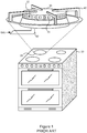
- FIG. 1 shows a schematic drawing of a known gas cooker 10.
- the gas cooker 10 has four heating elements 20 arranged on a flat top of the cooker 10.
- Each heating element 20 comprises a gas burner 30 having a plurality of gas outlets 31 and an ignition source 32.
- the gas burner 30 is constructed to receive flammable gas from an external source (e.g. a mains gas supply or a standalone gas tank) via a gas inlet pipe 50.
- the flowrate of gas to the heating element 20 is controllable via one or more valves (not shown).
- the one or more valves are opened sufficiently to allow gas to flow through the pipe 50 and out of the plurality of gas outlets 31.
- the outflowing gas is ignited (e.g. using ignition source 32), creating a flame which can be used to heat objects placed above the gas burner 30.
- Each heating element 20 is also provided with a support 40 for holding objects (such as pans or other vessels) above the gas burner 30.
- the size of the flame from the gas burner 30 is variable by controlling the flowrate of gas through the plurality of outlets 31.
- the valves on the gas inlet pipe 50 By adjusting the valves on the gas inlet pipe 50, the flowrate of gas through the burner 30 can be controlled.
- FIG. 2 shows a schematic drawing of an example heating element 200 in accordance with aspects disclosed herein.
- the heating element 200 in this example comprises a gas burner 230 having a plurality of gas outlets 231.
- the gas burner 230 is generally cylindrical in shape.
- the plurality of gas outlets 231 are arranged on the vertical edge or periphery of the gas burner 230. Other arrangements are possible.
- the gas burner 230 is connected to a gas inlet tube 250 such that gas can flow in through the inlet tube 250 and out of the plurality of gas outlets 231.
- the flowrate of gas through the inlet tube 250 is controllable via a valve 251 (described in more detail below).
- the gas burner 230 may have an ignition source (not shown in Figure 2 ) for igniting gas exiting the gas outlets 231.
- the gas may be ignited manually such as by a user introducing a lit match to light the gas.
- the gas burner 230 is constructed to provide a steady flow of gas from each outlet 231 which, when ignited, provides a flame for heating objects above the gas burner 230.
- a support 240 is provided for holding vessels or other objects above the gas burner 230. That is, an object can be rested on the support 240 to be heated by flames from the outlets 231.
- the support 240 is constructed out of a material which is both strong enough to support a vessel and to withstand heat from the flame of the gas burner 230.
- An example of a suitable material is steel.
- the support 240 may comprise one or more arms, as shown in Figure 2 (only two arms being shown in the figure) which protrude radially inward from outside the edge of the gas burner 230.
- the support 240 may be a different arrangement such as one or more rings of metal concentrically aligned with the gas burner 230.
- the example support shown in Figure 2 comprises arms which are stepped such that the height of the support increases in steps with increasing distance from the gas burner 230. This stepped arrangement has the advantage of intuitively guiding the user to place a vessel centrally on the support 240 (i.e. centrally aligned with the gas burner 230) because a particularly sized vessel will only rest stably in such a position.
- the heating element 200 is also provided with at least one magnet 241 and at least one proximity sensor 243.
- the proximity sensor 243 is constructed and configured to generate an output in response to a magnetic field.
- the magnet 241 is arranged such that it can be moved from a raised position to a lowered position closer to the proximity sensor 243.
- the raised position and lowered position are such that the magnet 241 causes the proximity sensor 243 to generate a different output at each position.
- the magnet 241 may trigger the proximity sensor 243 to generate an output when in the lowered position but not when in the raised position.
- Placement of a vessel on the support 240 may or may not move the or one or more of the magnets 241 to their respective lowered positions depending on the size (lateral extent) of the vessel.
- the nature of the output (or lack thereof) from the or each proximity sensor 243 can be used to provide an indication of the size (lateral extent) of the vessel. This is described in more detail below.
- the or each proximity sensor 243 may generate a binary output indicative (only) of whether a magnetic field strength locally at the proximity sensor 243 exceeds a threshold value, or may generate a continuous output indicative of the magnetic field strength itself.
- An example of a suitable binary proximity sensor is a reed switch.
- An example of a suitable continuous proximity sensor is a Hall sensor. In any case, the output of each proximity sensor 243 is different depending on whether or not one or more of the magnets 241 has been moved to the lowered position.
- each magnet 241 is mounted on a spring 242 which biases the magnet 241 to a raised position, as shown.
- the magnets 241 may be permanent magnets or may be electromagnets. When permanent magnets are used, depending on for example their location relative to the gas burner 230, they may be made of a magnetic material with a sufficiently high Curie temperature to withstand heat from the flame (or other heat source, when the cooker is a non-gas cooker). Examples of suitable materials include cobalt and alnico.
- each magnet 241 and spring 242 is such that the magnet 241 is movable in response to a vessel being placed on the support 240.
- each magnet 241 is provided with a respective spring 242 connected to the underside of the magnet 241 and holding the magnet 241 above the surface of the support 240.
- those magnets 241 will be pushed down by the weight of the vessel to a lower position.
- the vessel need not touch the magnets 241 to move the magnets 241; other elements, such as a bar, could be provided which are arranged to contact the vessel and move the magnets 241.
- placement of a vessel on the support 240 causes one or more of the magnets 241 to move relative to the at least one proximity sensor 243.
- the function of the spring 242 is to bias the at least one magnet 241 into a raised position at which it is outside a proximity of the at least one proximity sensor 243 (described in more detail below), i.e. to return the at least one magnet 241 to the raised position when the vessel is removed.
- the magnets 241 and proximity sensors 243 are arranged such that each proximity sensor 243 generates an output indicative of only a respective one of the magnets 241.
- the at least one proximity sensor 243 is configured to generate an output indicative of the at least one magnet 241 having been moved to be in the proximity of the proximity sensor 243. As mentioned above, this may be a simple (binary) output indicating that the proximity sensor 243 is subject to a magnetic field greater than a threshold strength. In such cases, the magnet 241 and proximity sensor 243 are arranged such that the field from the magnet 241 does not trigger the proximity sensor 243 to generate the output when the magnet 241 is in the raised position, but does trigger the proximity sensor 243 to generate the output when the magnet 241 is in the lowered position (when a vessel is placed on the cooker which lowers that magnet 241). Proximity sensors 243 in Figure 2 are shown as reed switches which function in this manner. This is also explained in more detail with reference to Figures 3A and 3B .
- each proximity sensor 243 is operably coupled (e.g. via one or more wired connections) to a controller 260.
- the controller 260 may be implemented as a processor configured to perform the functionality described herein.
- each proximity sensor 243 The output from each proximity sensor 243 is communicated to the controller 260 which can determine which magnets 241 are in the lowered position, because the output from each proximity sensor 243 varies depending on the position of one or more of the magnets 243.
- the magnets 241 are lowered in response to a vessel being placed on the cooker.
- which proximity sensors 243 generate an output is indicative of how large the (base of) the vessel currently resting on the cooker is.
- the controller 260 is configured to receive the output from the at least one sensor 243, and determine, based on the received output, a size of the vessel, in particular the radial or lateral extent of the vessel.
- the controller 260 is also operatively coupled to the valve 251 of the gas inlet 250.
- the valve 251 can be used to control the flowrate of gas to the gas burner 230 and thereby control the size of the flame.
- the controller 260 is arranged to control the gas flowrate, and thereby the size of the flame, via the valve 251.
- the controller 260 is configured to control the valve 251 to permit a flowrate resulting in a flame having a size no larger than the determined size (lateral extent) of the vessel (determined, by the controller 260, from the received output of the one or more proximity sensors 243).
- the controller 260 may control the valve 251 such that the size of the flame is at least generally equal to the determined size of the vessel.
- the size of the flame resulting from a particular valve position may be detectable by the controller 260 using one or more sensors, e.g. heat sensors arranged on the support (not shown).
- the controller 260 may be provided with a memory storing commissioning data indicating flame sizes from various valve positions, from which the controller 260 can determine an appropriate valve position to achieve a given flame size.
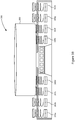
- FIGS 3A and 3B illustrate a second example of a heating element 300.
- the heating element 300 comprises, as before, a gas burner 230 having a plurality of gas outlets 231.
- the support 240 is flat (not stepped). Again, only two arms of the support 240 are shown. Each arm has four magnets 240 and four proximity sensors 243.
- the gas inlet pipe 250 and controller 260 are omitted in the figure for the sake of clarity.
- the proximity sensors 243 are, by way of example, reed switches.
- FIG 3A there is no vessel placed on the support 240. Hence, all of the magnets 241a-h remain in the raised position, supported by respective springs 242. Due to this, none of the reed switches 243a-h is subject to sufficient magnetic field to close and so all remain open as shown.
- a vessel 350 has been placed on the heating element 300.
- the size of the vessel 350 is such that the weight of the vessel 350 pushes the four innermost magnets 241c-f to the lowered position, but not the outermost magnets 241a-b and 241 g-h.
- the new position of the four innermost magnets 241c-f (in the lowered position, closer to their respective reed switches 243c-f) causes the innermost reed switches 243c-f to close, as shown.
- the outermost reed switches 243a-b and 243g-h are arranged to close in response to their respective magnets 241a-b and 241g-h being in the lowered position. This is not the case, and therefore these reed switches remain open.
- Reed switches are "passive" in the sense that they do not actively generate an output themselves. Instead, reed switches 243 may be used to control a respective current or voltage provided to the controller 260. In other examples of proximity sensors 243, the proximity sensors 243 themselves may actively generate an output. In any case, the controller 260 receives a different signal from each of the proximity sensors 243 depending on whether or not the respective magnet 241 for the proximity sensor 243 is in the raised or lowered position. The controller 260 processes the received signals to estimate a size of a vessel currently placed on the heating element 300. That is, the size (e.g. base diameter) of the vessel can be assumed to be equal to the distance between the further "activated" proximity sensors 243 (i.e. ones for which the respective signal indicates the respective magnet 241 is in the lowered position).
- the size e.g. base diameter
- the proximity sensors 243 may be considered in groups, each group comprising a set of proximity sensors 243 an equal distance from the centre of the gas burner 230.
- a first group may comprise innermost proximity sensors 243d and 243e; a second group may comprise second innermost proximity sensors 243c and 243f; a third group may comprise second outermost proximity sensors 243b and 243g; and a fourth group may comprise outermost proximity sensors 243a and 243h.
- Further proximity sensors may be in each group in a corresponding manner for additional arms of the support 240 not shown in Figures 3A and 3B (when present).
- controller 260 may be preconfigured with a suitable valve position to generate a specific flame size by allowed a particular gas level to flow through the gas burner 230.
- Table 1 (below) illustrates an example configuration table for controller 260.
- the configuration table may be stored in a memory (e.g. a local data storage) accessible by the controller 260.
- the controller 260 may be configured to receive one or more outputs from the proximity sensors 243, determine the highest group (largest spatial extent) to which an active proximity sensor belongs, look up the appropriate valve position for that group in the table, and control the valve 251 to be at that position. Thereby, the controller 260 controls the flame to have the same spatial extend (radially outwards from the centre of the gas burner 230) as the vessel currently placed on the heating element 300.
- an electric cooker may be provided with a plurality of concentrically arranged resistive heating ring elements having different sizes.
- the steps performed by the controller 260 described above in relation to the controlling the valve 251 may then be replaced by steps of controlling a current to respective ones of the ring elements. That is, the controller 260 may control how much of the electric cooker is activated to generate heat in dependence on a detected size of a vessel placed on an electric cooker.
- a further example of a cooker is an induction cooker.
- the controller 260 may control an active heating area of the induction cooker to vary in response to a determined size of a vessel placed on an induction cooker.
- processor or processing system or circuitry referred to herein may in practice be provided by a single chip or integrated circuit or plural chips or integrated circuits, optionally provided as a chipset, an application-specific integrated circuit (ASIC), field-programmable gate array (FPGA), digital signal processor (DSP), graphics processing units (GPUs), etc.
- the chip or chips may comprise circuitry (as well as possibly firmware) for embodying at least one or more of a data processor or processors, a digital signal processor or processors, baseband circuitry and radio frequency circuitry, which are configurable so as to operate in accordance with the exemplary embodiments.
- the exemplary embodiments may be implemented at least in part by computer software stored in (non-transitory) memory and executable by the processor, or by hardware, or by a combination of tangibly stored software and hardware (and tangibly stored firmware).
- the invention also extends to computer programs, particularly computer programs on or in a carrier, adapted for putting the invention into practice.
- the program may be in the form of non-transitory source code, object code, a code intermediate source and object code such as in partially compiled form, or in any other non-transitory form suitable for use in the implementation of processes according to the invention.
- the carrier may be any entity or device capable of carrying the program.
- the carrier may comprise a storage medium, such as a solid-state drive (SSD) or other semiconductor-based RAM; a ROM, for example a CD ROM or a semiconductor ROM; a magnetic recording medium, for example a floppy disk or hard disk; optical memory devices in general; etc.
- SSD solid-state drive
- ROM read-only memory
- magnetic recording medium for example a floppy disk or hard disk
- optical memory devices in general etc.
Landscapes
- Engineering & Computer Science (AREA)
- Chemical & Material Sciences (AREA)
- Combustion & Propulsion (AREA)
- Mechanical Engineering (AREA)
- General Engineering & Computer Science (AREA)
- Regulation And Control Of Combustion (AREA)
- Electric Stoves And Ranges (AREA)
Abstract
Description
- The present disclosure relates to a cooking apparatus and method of operating a cooking apparatus.
- A cooker (also called a stove) is an apparatus for heating foodstuffs, though it can be used to heat other materials. A traditional cooker comprises a flat top with one or more heating elements. The heating elements controllably generate heat such that any items placed on or above them will be heated. Thus, a foodstuff can be heated by placing it (in a vessel) on or above a heating element of the cooker.
- Typical heating elements employed in cookers include gas burners, electric elements, or induction elements, which each generate heat using a different mechanism.
- According to a first aspect disclosed herein, there is provided a cooker for heating a cooking vessel, the cooker comprising: a heating element for generating heat at an active area of the heating element; a proximity sensor; a magnet arranged to move relative to the proximity sensor when a cooking vessel is placed on the heating element; the proximity sensor being configured to generate an output indicative of the magnet having been moved to be in the proximity of the proximity sensor; and the cooker being arranged such that the heating element is controlled based on the output from the proximity sensor such that the active area does not exceed the determined base area of the cooking vessel.
- In an example, the cooker is arranged such that the heating element is controlled such that the active area is equal to a base area of a cooking vessel placed on the heating element.
- In an example, the cooker comprises a plurality of magnets arranged to move relative to the proximity sensor when a cooking vessel is placed on the heating element, and the magnets are arranged such that different sized cooking vessels cause different ones of the magnets to move.
- In an example, the cooker comprises a plurality of proximity sensors arranged at different locations relative to the heating element.
- In an example, the cooker comprises a gas burner heating element, the active area corresponding to a flame generated by the gas burner in use; and the cooker is arranged to control the gas burner by controlling a flow of gas to the gas burner such that the flame does not exceed the determined base area of the cooking vessel.
- In an example, the cooker comprises an electric heating element, the active area being an area of the electric element controlled to generate heat; and the cooker is arranged to control the electric element such that the area of the electric element generating heat does not exceed the determined base area of the cooking vessel.
- In an example, the cooker comprises a biasing device for biasing the or each magnet away from the or each respective proximity sensor.
- According to a second aspect disclosed herein, there is provided a method of controlling a heating element to heat a cooking vessel, the method comprising: receiving, from a proximity sensor, an output indicative of a magnet having been moved to be in the proximity of the proximity sensor when a cooking vessel is placed on the heating element; determining, based on the received output, a base area of a said cooking vessel; and controlling an active area of a heating element such that the active area does not exceed the determined base area of a said cooking vessel.
- In an example, the method comprises controlling the active area of the heating element such that the active area is equal to a base area of a said cooking vessel.
- In an example, the heating element comprises a gas burner heating element, the active area corresponding to a flame generated by the gas burner in use; and the method comprises controlling the gas burner by controlling a flow of gas to the gas burner such that the flame does not exceed the determined base area of the cooking vessel.
- In an example, the heating element comprises an electric heating element, the active area being an area of the electric element controlled to generate heat; and the method comprises controlling the electric element such that the area of the electric element generating heat does not exceed the determined base area of the cooking vessel.
- To assist understanding of the present disclosure and to show how embodiments may be put into effect, reference is made by way of example to the accompanying drawings in which:
-
Figure 1 shows schematically a cooker as known in the art; -
Figure 2 shows schematically an example of a heating element for a cooker according to aspects described herein; and -
Figures 3A and3B show a further example of a heating element for a cooker according to aspects described herein. -
Figure 1 shows a schematic drawing of a knowngas cooker 10. Thegas cooker 10 has fourheating elements 20 arranged on a flat top of thecooker 10. Eachheating element 20 comprises agas burner 30 having a plurality ofgas outlets 31 and anignition source 32. - The
gas burner 30 is constructed to receive flammable gas from an external source (e.g. a mains gas supply or a standalone gas tank) via agas inlet pipe 50. The flowrate of gas to theheating element 20 is controllable via one or more valves (not shown). To use thecooker 10, the one or more valves are opened sufficiently to allow gas to flow through thepipe 50 and out of the plurality ofgas outlets 31. The outflowing gas is ignited (e.g. using ignition source 32), creating a flame which can be used to heat objects placed above thegas burner 30. Eachheating element 20 is also provided with asupport 40 for holding objects (such as pans or other vessels) above thegas burner 30. - The size of the flame from the
gas burner 30 is variable by controlling the flowrate of gas through the plurality ofoutlets 31. By adjusting the valves on thegas inlet pipe 50, the flowrate of gas through theburner 30 can be controlled. There is a minimum flowrate required to maintain an ignited flame. Above this minimum flowrate, increasing the flowrate has the effect of increasing the size of the flame from eachoutlet 31. Hence, increasing the flowrate (by opening the one or more valves) of gas will increase the radial extent of the flame. -
Figure 2 shows a schematic drawing of anexample heating element 200 in accordance with aspects disclosed herein. Theheating element 200 in this example comprises agas burner 230 having a plurality ofgas outlets 231. Thegas burner 230 is generally cylindrical in shape. The plurality ofgas outlets 231 are arranged on the vertical edge or periphery of thegas burner 230. Other arrangements are possible. - The
gas burner 230 is connected to agas inlet tube 250 such that gas can flow in through theinlet tube 250 and out of the plurality ofgas outlets 231. The flowrate of gas through theinlet tube 250 is controllable via a valve 251 (described in more detail below). Thegas burner 230 may have an ignition source (not shown inFigure 2 ) for igniting gas exiting thegas outlets 231. Alternatively, the gas may be ignited manually such as by a user introducing a lit match to light the gas. In any case, thegas burner 230 is constructed to provide a steady flow of gas from eachoutlet 231 which, when ignited, provides a flame for heating objects above thegas burner 230. - A
support 240 is provided for holding vessels or other objects above thegas burner 230. That is, an object can be rested on thesupport 240 to be heated by flames from theoutlets 231. - The
support 240 is constructed out of a material which is both strong enough to support a vessel and to withstand heat from the flame of thegas burner 230. An example of a suitable material is steel. Thesupport 240 may comprise one or more arms, as shown inFigure 2 (only two arms being shown in the figure) which protrude radially inward from outside the edge of thegas burner 230. In other examples, thesupport 240 may be a different arrangement such as one or more rings of metal concentrically aligned with thegas burner 230. The example support shown inFigure 2 comprises arms which are stepped such that the height of the support increases in steps with increasing distance from thegas burner 230. This stepped arrangement has the advantage of intuitively guiding the user to place a vessel centrally on the support 240 (i.e. centrally aligned with the gas burner 230) because a particularly sized vessel will only rest stably in such a position. - The
heating element 200 is also provided with at least onemagnet 241 and at least oneproximity sensor 243. Theproximity sensor 243 is constructed and configured to generate an output in response to a magnetic field. Themagnet 241 is arranged such that it can be moved from a raised position to a lowered position closer to theproximity sensor 243. The raised position and lowered position are such that themagnet 241 causes theproximity sensor 243 to generate a different output at each position. For example, themagnet 241 may trigger theproximity sensor 243 to generate an output when in the lowered position but not when in the raised position. Placement of a vessel on thesupport 240 may or may not move the or one or more of themagnets 241 to their respective lowered positions depending on the size (lateral extent) of the vessel. Thereby, the nature of the output (or lack thereof) from the or eachproximity sensor 243 can be used to provide an indication of the size (lateral extent) of the vessel. This is described in more detail below. - The or each
proximity sensor 243 may generate a binary output indicative (only) of whether a magnetic field strength locally at theproximity sensor 243 exceeds a threshold value, or may generate a continuous output indicative of the magnetic field strength itself. An example of a suitable binary proximity sensor is a reed switch. An example of a suitable continuous proximity sensor is a Hall sensor. In any case, the output of eachproximity sensor 243 is different depending on whether or not one or more of themagnets 241 has been moved to the lowered position. - In the example of
Figure 2 , there areplural magnets 241 and pluralcorresponding proximity sensors 243. In this example, eachmagnet 241 is mounted on aspring 242 which biases themagnet 241 to a raised position, as shown. Themagnets 241 may be permanent magnets or may be electromagnets. When permanent magnets are used, depending on for example their location relative to thegas burner 230, they may be made of a magnetic material with a sufficiently high Curie temperature to withstand heat from the flame (or other heat source, when the cooker is a non-gas cooker). Examples of suitable materials include cobalt and alnico. - The arrangement of each
magnet 241 andspring 242 is such that themagnet 241 is movable in response to a vessel being placed on thesupport 240. In the example ofFigure 2 , eachmagnet 241 is provided with arespective spring 242 connected to the underside of themagnet 241 and holding themagnet 241 above the surface of thesupport 240. Hence, if a vessel is placed on thesupport 240 which contacts one or more of themagnets 241, thosemagnets 241 will be pushed down by the weight of the vessel to a lower position. Other arrangements are possible. For example, the vessel need not touch themagnets 241 to move themagnets 241; other elements, such as a bar, could be provided which are arranged to contact the vessel and move themagnets 241. - In any case, placement of a vessel on the
support 240 causes one or more of themagnets 241 to move relative to the at least oneproximity sensor 243. The function of thespring 242 is to bias the at least onemagnet 241 into a raised position at which it is outside a proximity of the at least one proximity sensor 243 (described in more detail below), i.e. to return the at least onemagnet 241 to the raised position when the vessel is removed. - In the example of
Figure 2 , themagnets 241 andproximity sensors 243 are arranged such that eachproximity sensor 243 generates an output indicative of only a respective one of themagnets 241. - The at least one
proximity sensor 243 is configured to generate an output indicative of the at least onemagnet 241 having been moved to be in the proximity of theproximity sensor 243. As mentioned above, this may be a simple (binary) output indicating that theproximity sensor 243 is subject to a magnetic field greater than a threshold strength. In such cases, themagnet 241 andproximity sensor 243 are arranged such that the field from themagnet 241 does not trigger theproximity sensor 243 to generate the output when themagnet 241 is in the raised position, but does trigger theproximity sensor 243 to generate the output when themagnet 241 is in the lowered position (when a vessel is placed on the cooker which lowers that magnet 241).Proximity sensors 243 inFigure 2 are shown as reed switches which function in this manner. This is also explained in more detail with reference toFigures 3A and3B . - In this example, each
proximity sensor 243 is operably coupled (e.g. via one or more wired connections) to acontroller 260. Thecontroller 260 may be implemented as a processor configured to perform the functionality described herein. - The output from each
proximity sensor 243 is communicated to thecontroller 260 which can determine whichmagnets 241 are in the lowered position, because the output from eachproximity sensor 243 varies depending on the position of one or more of themagnets 243. Themagnets 241 are lowered in response to a vessel being placed on the cooker. Hence, whichproximity sensors 243 generate an output is indicative of how large the (base of) the vessel currently resting on the cooker is. In other words, thecontroller 260 is configured to receive the output from the at least onesensor 243, and determine, based on the received output, a size of the vessel, in particular the radial or lateral extent of the vessel. - In this example, the
controller 260 is also operatively coupled to thevalve 251 of thegas inlet 250. As mentioned above, thevalve 251 can be used to control the flowrate of gas to thegas burner 230 and thereby control the size of the flame. Thecontroller 260 is arranged to control the gas flowrate, and thereby the size of the flame, via thevalve 251. Specifically, thecontroller 260 is configured to control thevalve 251 to permit a flowrate resulting in a flame having a size no larger than the determined size (lateral extent) of the vessel (determined, by thecontroller 260, from the received output of the one or more proximity sensors 243). In other examples, thecontroller 260 may control thevalve 251 such that the size of the flame is at least generally equal to the determined size of the vessel. - The size of the flame resulting from a particular valve position may be detectable by the
controller 260 using one or more sensors, e.g. heat sensors arranged on the support (not shown). Alternatively, thecontroller 260 may be provided with a memory storing commissioning data indicating flame sizes from various valve positions, from which thecontroller 260 can determine an appropriate valve position to achieve a given flame size. -
Figures 3A and3B illustrate a second example of aheating element 300. Theheating element 300 comprises, as before, agas burner 230 having a plurality ofgas outlets 231. In this example, however, thesupport 240 is flat (not stepped). Again, only two arms of thesupport 240 are shown. Each arm has fourmagnets 240 and fourproximity sensors 243. Thegas inlet pipe 250 andcontroller 260 are omitted in the figure for the sake of clarity. - The
proximity sensors 243 are, by way of example, reed switches. InFigure 3A , there is no vessel placed on thesupport 240. Hence, all of themagnets 241a-h remain in the raised position, supported byrespective springs 242. Due to this, none of thereed switches 243a-h is subject to sufficient magnetic field to close and so all remain open as shown. - In
Figure 3B , avessel 350 has been placed on theheating element 300. The size of thevessel 350 is such that the weight of thevessel 350 pushes the fourinnermost magnets 241c-f to the lowered position, but not theoutermost magnets 241a-b and 241 g-h. The new position of the fourinnermost magnets 241c-f (in the lowered position, closer to theirrespective reed switches 243c-f) causes theinnermost reed switches 243c-f to close, as shown. Theoutermost reed switches 243a-b and 243g-h are arranged to close in response to theirrespective magnets 241a-b and 241g-h being in the lowered position. This is not the case, and therefore these reed switches remain open. - Reed switches are "passive" in the sense that they do not actively generate an output themselves. Instead,
reed switches 243 may be used to control a respective current or voltage provided to thecontroller 260. In other examples ofproximity sensors 243, theproximity sensors 243 themselves may actively generate an output. In any case, thecontroller 260 receives a different signal from each of theproximity sensors 243 depending on whether or not therespective magnet 241 for theproximity sensor 243 is in the raised or lowered position. Thecontroller 260 processes the received signals to estimate a size of a vessel currently placed on theheating element 300. That is, the size (e.g. base diameter) of the vessel can be assumed to be equal to the distance between the further "activated" proximity sensors 243 (i.e. ones for which the respective signal indicates therespective magnet 241 is in the lowered position). - The
proximity sensors 243 may be considered in groups, each group comprising a set ofproximity sensors 243 an equal distance from the centre of thegas burner 230. For example, inFigures 3A and3B : a first group may compriseinnermost proximity sensors innermost proximity sensors outermost proximity sensors outermost proximity sensors support 240 not shown inFigures 3A and3B (when present). - As mentioned above, the
controller 260 may be preconfigured with a suitable valve position to generate a specific flame size by allowed a particular gas level to flow through thegas burner 230. Table 1 (below) illustrates an example configuration table forcontroller 260.
- The configuration table may be stored in a memory (e.g. a local data storage) accessible by the
controller 260. Thecontroller 260 may be configured to receive one or more outputs from theproximity sensors 243, determine the highest group (largest spatial extent) to which an active proximity sensor belongs, look up the appropriate valve position for that group in the table, and control thevalve 251 to be at that position. Thereby, thecontroller 260 controls the flame to have the same spatial extend (radially outwards from the centre of the gas burner 230) as the vessel currently placed on theheating element 300. - Although the above has been described in terms of gas cookers, it is understood that other types of cooker may be used for which an active heating area (the flame size as above) is controllable variable in size. For example, an electric cooker may be provided with a plurality of concentrically arranged resistive heating ring elements having different sizes. The steps performed by the
controller 260 described above in relation to the controlling thevalve 251 may then be replaced by steps of controlling a current to respective ones of the ring elements. That is, thecontroller 260 may control how much of the electric cooker is activated to generate heat in dependence on a detected size of a vessel placed on an electric cooker. - A further example of a cooker is an induction cooker. Again, the
controller 260 may control an active heating area of the induction cooker to vary in response to a determined size of a vessel placed on an induction cooker. - It will be understood that the processor or processing system or circuitry referred to herein may in practice be provided by a single chip or integrated circuit or plural chips or integrated circuits, optionally provided as a chipset, an application-specific integrated circuit (ASIC), field-programmable gate array (FPGA), digital signal processor (DSP), graphics processing units (GPUs), etc. The chip or chips may comprise circuitry (as well as possibly firmware) for embodying at least one or more of a data processor or processors, a digital signal processor or processors, baseband circuitry and radio frequency circuitry, which are configurable so as to operate in accordance with the exemplary embodiments. In this regard, the exemplary embodiments may be implemented at least in part by computer software stored in (non-transitory) memory and executable by the processor, or by hardware, or by a combination of tangibly stored software and hardware (and tangibly stored firmware).
- Reference is made herein to data storage for storing data. This may be provided by a single device or by plural devices. Suitable devices include for example a hard disk and non-volatile semiconductor memory.
- Although at least some aspects of the embodiments described herein with reference to the drawings comprise computer processes performed in processing systems or processors, the invention also extends to computer programs, particularly computer programs on or in a carrier, adapted for putting the invention into practice. The program may be in the form of non-transitory source code, object code, a code intermediate source and object code such as in partially compiled form, or in any other non-transitory form suitable for use in the implementation of processes according to the invention. The carrier may be any entity or device capable of carrying the program. For example, the carrier may comprise a storage medium, such as a solid-state drive (SSD) or other semiconductor-based RAM; a ROM, for example a CD ROM or a semiconductor ROM; a magnetic recording medium, for example a floppy disk or hard disk; optical memory devices in general; etc.
- The examples described herein are to be understood as illustrative examples of embodiments of the invention. Further embodiments and examples are envisaged. Any feature described in relation to any one example or embodiment may be used alone or in combination with other features. In addition, any feature described in relation to any one example or embodiment may also be used in combination with one or more features of any other of the examples or embodiments, or any combination of any other of the examples or embodiments. Furthermore, equivalents and modifications not described herein may also be employed within the scope of the invention, which is defined in the claims.
Claims (11)
- A cooker for heating a cooking vessel, the cooker comprising:a heating element for generating heat at an active area of the heating element;a proximity sensor;a magnet arranged to move relative to the proximity sensor when a cooking vessel is placed on the heating element;the proximity sensor being configured to generate an output indicative of the magnet having been moved to be in the proximity of the proximity sensor; andthe cooker being arranged such that the heating element is controlled based on the output from the proximity sensor such that the active area does not exceed the determined base area of the cooking vessel.
- A cooker according to claim 1, the cooker being arranged such that the heating element is controlled such that the active area is equal to a base area of a cooking vessel placed on the heating element.
- A cooker according to claim 1 or 2, comprising a plurality of magnets arranged to move relative to the proximity sensor when a cooking vessel is placed on the heating element, the magnets being arranged such that different sized cooking vessels cause different ones of the magnets to move.
- A cooker according to any of claims 1 to 3, comprising a plurality of proximity sensors arranged at different locations relative to the heating element.
- A cooker according to any of claims 1 to 4, comprising a gas burner heating element, the active area corresponding to a flame generated by the gas burner in use; the cooker being arranged to control the gas burner by controlling a flow of gas to the gas burner such that the flame does not exceed the determined base area of the cooking vessel.
- A cooker according to any of claims 1 to 5, comprising an electric heating element, the active area being an area of the electric element controlled to generate heat; the cooker being arranged to control the electric element such that the area of the electric element generating heat does not exceed the determined base area of the cooking vessel.
- A cooker according to any of claims 1 to 6, comprising a biasing device for biasing the or each magnet away from the or each respective proximity sensor.
- A method of controlling a heating element to heat a cooking vessel, the method comprising:receiving, from a proximity sensor, an output indicative of a magnet having been moved to be in the proximity of the proximity sensor when a cooking vessel is placed on the heating element;determining, based on the received output, a base area of a said cooking vessel; andcontrolling an active area of a heating element such that the active area does not exceed the determined base area of a said cooking vessel.
- A method according to claim 8, comprising controlling the active area of the heating element such that the active area is equal to a base area of a said cooking vessel.
- A method according to claim 8 or claim 9, wherein the heating element comprises a gas burner heating element, the active area corresponding to a flame generated by the gas burner in use; the method comprising controlling the gas burner by controlling a flow of gas to the gas burner such that the flame does not exceed the determined base area of the cooking vessel.
- A method according to any of claims 8 to 10, wherein the heating element comprises an electric heating element, the active area being an area of the electric element controlled to generate heat; the method comprising controlling the electric element such that the area of the electric element generating heat does not exceed the determined base area of the cooking vessel.
Priority Applications (2)
| Application Number | Priority Date | Filing Date | Title |
|---|---|---|---|
| EP17199140.9A EP3477204A1 (en) | 2017-10-30 | 2017-10-30 | Cooking apparatus and method of operating |
| TR2017/19018A TR201719018A2 (en) | 2017-10-30 | 2017-11-28 | Cooking apparatus and method of operating. |
Applications Claiming Priority (1)
| Application Number | Priority Date | Filing Date | Title |
|---|---|---|---|
| EP17199140.9A EP3477204A1 (en) | 2017-10-30 | 2017-10-30 | Cooking apparatus and method of operating |
Publications (1)
| Publication Number | Publication Date |
|---|---|
| EP3477204A1 true EP3477204A1 (en) | 2019-05-01 |
Family
ID=60191247
Family Applications (1)
| Application Number | Title | Priority Date | Filing Date |
|---|---|---|---|
| EP17199140.9A Withdrawn EP3477204A1 (en) | 2017-10-30 | 2017-10-30 | Cooking apparatus and method of operating |
Country Status (2)
| Country | Link |
|---|---|
| EP (1) | EP3477204A1 (en) |
| TR (1) | TR201719018A2 (en) |
Cited By (2)
| Publication number | Priority date | Publication date | Assignee | Title |
|---|---|---|---|---|
| CN112762481A (en) * | 2019-11-11 | 2021-05-07 | 盛菊芳 | Automatic flame adjusting type gas stove based on gravity transmission and use method thereof |
| CN114688577A (en) * | 2020-12-29 | 2022-07-01 | 佛山市顺德区美的电热电器制造有限公司 | Method for pairing temperature sensing elements in heating equipment and method for determining heating area |
Citations (6)
| Publication number | Priority date | Publication date | Assignee | Title |
|---|---|---|---|---|
| US5658478A (en) * | 1994-05-03 | 1997-08-19 | Roeschel; Hans E. | Automatic heating assembly with selective heating |
| JP2006118817A (en) * | 2004-10-25 | 2006-05-11 | Matsushita Electric Ind Co Ltd | Cooker |
| JP2008138912A (en) * | 2006-11-30 | 2008-06-19 | Osaka Gas Co Ltd | Cooking stove |
| JP4146494B1 (en) * | 2007-03-15 | 2008-09-10 | 拓平 山本 | Cooker |
| JP2013068395A (en) * | 2011-09-26 | 2013-04-18 | Tokyo Gas Co Ltd | Heating cooker |
| DE102013209155A1 (en) * | 2013-05-16 | 2014-12-04 | E.G.O. Elektro-Gerätebau GmbH | Gas burner for a gas hob and gas hob |
-
2017
- 2017-10-30 EP EP17199140.9A patent/EP3477204A1/en not_active Withdrawn
- 2017-11-28 TR TR2017/19018A patent/TR201719018A2/en unknown
Patent Citations (6)
| Publication number | Priority date | Publication date | Assignee | Title |
|---|---|---|---|---|
| US5658478A (en) * | 1994-05-03 | 1997-08-19 | Roeschel; Hans E. | Automatic heating assembly with selective heating |
| JP2006118817A (en) * | 2004-10-25 | 2006-05-11 | Matsushita Electric Ind Co Ltd | Cooker |
| JP2008138912A (en) * | 2006-11-30 | 2008-06-19 | Osaka Gas Co Ltd | Cooking stove |
| JP4146494B1 (en) * | 2007-03-15 | 2008-09-10 | 拓平 山本 | Cooker |
| JP2013068395A (en) * | 2011-09-26 | 2013-04-18 | Tokyo Gas Co Ltd | Heating cooker |
| DE102013209155A1 (en) * | 2013-05-16 | 2014-12-04 | E.G.O. Elektro-Gerätebau GmbH | Gas burner for a gas hob and gas hob |
Cited By (2)
| Publication number | Priority date | Publication date | Assignee | Title |
|---|---|---|---|---|
| CN112762481A (en) * | 2019-11-11 | 2021-05-07 | 盛菊芳 | Automatic flame adjusting type gas stove based on gravity transmission and use method thereof |
| CN114688577A (en) * | 2020-12-29 | 2022-07-01 | 佛山市顺德区美的电热电器制造有限公司 | Method for pairing temperature sensing elements in heating equipment and method for determining heating area |
Also Published As
| Publication number | Publication date |
|---|---|
| TR201719018A2 (en) | 2019-05-21 |
Similar Documents
| Publication | Publication Date | Title |
|---|---|---|
| RU2651734C2 (en) | Cross heating thermocouple based pan sensing method | |
| CN102770711B (en) | Gas stoves | |
| US10584882B2 (en) | Electric cooktop appliance with heat control | |
| US10788220B2 (en) | Determining cookware location on a cooktop appliance based on temperature response | |
| US11435086B2 (en) | Cooktop appliance and methods of operation | |
| KR101632742B1 (en) | Induction range | |
| CN113544435B (en) | Temperature probe for cooktop appliances with gas burners | |
| KR20110076166A (en) | Automatic burner control device and method according to cooking vessel detection of electric stove | |
| JP2023509776A5 (en) | ||
| KR101529116B1 (en) | An apparatus of controlling overheating protection of gas cooktop for extending life of its battery and the method thereof | |
| KR101359103B1 (en) | Gas range forming automatically the heating area suitable for the bottom surface of a cooking container by combining plural numbers of small-sized gas burner heads and controlling method thereof | |
| US11274826B2 (en) | Delayed ignition prevention in a multi-ring gas burner for a cooktop appliance | |
| KR101614089B1 (en) | Induction range | |
| US11041622B2 (en) | Gas cooktop with power management | |
| EP3742054A1 (en) | Cooking appliance and method of operating a cooking appliance | |
| US20190174581A1 (en) | Electric cooktop appliance | |
| US11788729B2 (en) | Cooking appliance with integrated touch sensing controls | |
| US11739941B2 (en) | Cooking appliance with multi-burner gas oven control | |
| US10634541B2 (en) | Methods for safe operation of a cooktop appliance | |
| KR20190112981A (en) | Apparatus and method for detecting movements of cooking container for induction range | |
| KR20230076591A (en) | Electric range | |
| JP2006118817A (en) | Cooker | |
| EP3490337A1 (en) | A heating appliance | |
| CN109199091A (en) | A kind of auto-controlled energy-saving type steam stove | |
| US12607360B2 (en) | Flame rectification circuit system for a gas cooktop |
Legal Events
| Date | Code | Title | Description |
|---|---|---|---|
| PUAI | Public reference made under article 153(3) epc to a published international application that has entered the european phase |
Free format text: ORIGINAL CODE: 0009012 |
|
| STAA | Information on the status of an ep patent application or granted ep patent |
Free format text: STATUS: THE APPLICATION HAS BEEN PUBLISHED |
|
| AK | Designated contracting states |
Kind code of ref document: A1 Designated state(s): AL AT BE BG CH CY CZ DE DK EE ES FI FR GB GR HR HU IE IS IT LI LT LU LV MC MK MT NL NO PL PT RO RS SE SI SK SM TR |
|
| AX | Request for extension of the european patent |
Extension state: BA ME |
|
| STAA | Information on the status of an ep patent application or granted ep patent |
Free format text: STATUS: REQUEST FOR EXAMINATION WAS MADE |
|
| 17P | Request for examination filed |
Effective date: 20191031 |
|
| RBV | Designated contracting states (corrected) |
Designated state(s): AL AT BE BG CH CY CZ DE DK EE ES FI FR GB GR HR HU IE IS IT LI LT LU LV MC MK MT NL NO PL PT RO RS SE SI SK SM TR |
|
| STAA | Information on the status of an ep patent application or granted ep patent |
Free format text: STATUS: EXAMINATION IS IN PROGRESS |
|
| 17Q | First examination report despatched |
Effective date: 20200504 |
|
| STAA | Information on the status of an ep patent application or granted ep patent |
Free format text: STATUS: THE APPLICATION HAS BEEN WITHDRAWN |
|
| 18W | Application withdrawn |
Effective date: 20200930 |