EP3477191A1 - Light fixture, preferably for stage - Google Patents
Light fixture, preferably for stage Download PDFInfo
- Publication number
- EP3477191A1 EP3477191A1 EP18202418.2A EP18202418A EP3477191A1 EP 3477191 A1 EP3477191 A1 EP 3477191A1 EP 18202418 A EP18202418 A EP 18202418A EP 3477191 A1 EP3477191 A1 EP 3477191A1
- Authority
- EP
- European Patent Office
- Prior art keywords
- light
- light sources
- fixture according
- optical
- light fixture
- Prior art date
- Legal status (The legal status is an assumption and is not a legal conclusion. Google has not performed a legal analysis and makes no representation as to the accuracy of the status listed.)
- Withdrawn
Links
Images



Classifications
-
- F—MECHANICAL ENGINEERING; LIGHTING; HEATING; WEAPONS; BLASTING
- F21—LIGHTING
- F21S—NON-PORTABLE LIGHTING DEVICES; SYSTEMS THEREOF; VEHICLE LIGHTING DEVICES SPECIALLY ADAPTED FOR VEHICLE EXTERIORS
- F21S8/00—Lighting devices intended for fixed installation
- F21S8/02—Lighting devices intended for fixed installation of recess-mounted type, e.g. downlighters
-
- F—MECHANICAL ENGINEERING; LIGHTING; HEATING; WEAPONS; BLASTING
- F21—LIGHTING
- F21K—NON-ELECTRIC LIGHT SOURCES USING LUMINESCENCE; LIGHT SOURCES USING ELECTROCHEMILUMINESCENCE; LIGHT SOURCES USING CHARGES OF COMBUSTIBLE MATERIAL; LIGHT SOURCES USING SEMICONDUCTOR DEVICES AS LIGHT-GENERATING ELEMENTS; LIGHT SOURCES NOT OTHERWISE PROVIDED FOR
- F21K9/00—Light sources using semiconductor devices as light-generating elements, e.g. using light-emitting diodes [LED] or lasers
- F21K9/60—Optical arrangements integrated in the light source, e.g. for improving the colour rendering index or the light extraction
- F21K9/62—Optical arrangements integrated in the light source, e.g. for improving the colour rendering index or the light extraction using mixing chambers, e.g. housings with reflective walls
-
- F—MECHANICAL ENGINEERING; LIGHTING; HEATING; WEAPONS; BLASTING
- F21—LIGHTING
- F21S—NON-PORTABLE LIGHTING DEVICES; SYSTEMS THEREOF; VEHICLE LIGHTING DEVICES SPECIALLY ADAPTED FOR VEHICLE EXTERIORS
- F21S10/00—Lighting devices or systems producing a varying lighting effect
-
- F—MECHANICAL ENGINEERING; LIGHTING; HEATING; WEAPONS; BLASTING
- F21—LIGHTING
- F21V—FUNCTIONAL FEATURES OR DETAILS OF LIGHTING DEVICES OR SYSTEMS THEREOF; STRUCTURAL COMBINATIONS OF LIGHTING DEVICES WITH OTHER ARTICLES, NOT OTHERWISE PROVIDED FOR
- F21V14/00—Controlling the distribution of the light emitted by adjustment of elements
- F21V14/06—Controlling the distribution of the light emitted by adjustment of elements by movement of refractors
-
- F—MECHANICAL ENGINEERING; LIGHTING; HEATING; WEAPONS; BLASTING
- F21—LIGHTING
- F21V—FUNCTIONAL FEATURES OR DETAILS OF LIGHTING DEVICES OR SYSTEMS THEREOF; STRUCTURAL COMBINATIONS OF LIGHTING DEVICES WITH OTHER ARTICLES, NOT OTHERWISE PROVIDED FOR
- F21V19/00—Fastening of light sources or lamp holders
- F21V19/001—Fastening of light sources or lamp holders the light sources being semiconductors devices, e.g. LEDs
-
- F—MECHANICAL ENGINEERING; LIGHTING; HEATING; WEAPONS; BLASTING
- F21—LIGHTING
- F21V—FUNCTIONAL FEATURES OR DETAILS OF LIGHTING DEVICES OR SYSTEMS THEREOF; STRUCTURAL COMBINATIONS OF LIGHTING DEVICES WITH OTHER ARTICLES, NOT OTHERWISE PROVIDED FOR
- F21V29/00—Protecting lighting devices from thermal damage; Cooling or heating arrangements specially adapted for lighting devices or systems
- F21V29/50—Cooling arrangements
-
- F—MECHANICAL ENGINEERING; LIGHTING; HEATING; WEAPONS; BLASTING
- F21—LIGHTING
- F21V—FUNCTIONAL FEATURES OR DETAILS OF LIGHTING DEVICES OR SYSTEMS THEREOF; STRUCTURAL COMBINATIONS OF LIGHTING DEVICES WITH OTHER ARTICLES, NOT OTHERWISE PROVIDED FOR
- F21V5/00—Refractors for light sources
- F21V5/002—Refractors for light sources using microoptical elements for redirecting or diffusing light
- F21V5/004—Refractors for light sources using microoptical elements for redirecting or diffusing light using microlenses
-
- F—MECHANICAL ENGINEERING; LIGHTING; HEATING; WEAPONS; BLASTING
- F21—LIGHTING
- F21V—FUNCTIONAL FEATURES OR DETAILS OF LIGHTING DEVICES OR SYSTEMS THEREOF; STRUCTURAL COMBINATIONS OF LIGHTING DEVICES WITH OTHER ARTICLES, NOT OTHERWISE PROVIDED FOR
- F21V5/00—Refractors for light sources
- F21V5/007—Array of lenses or refractors for a cluster of light sources, e.g. for arrangement of multiple light sources in one plane
-
- F—MECHANICAL ENGINEERING; LIGHTING; HEATING; WEAPONS; BLASTING
- F21—LIGHTING
- F21V—FUNCTIONAL FEATURES OR DETAILS OF LIGHTING DEVICES OR SYSTEMS THEREOF; STRUCTURAL COMBINATIONS OF LIGHTING DEVICES WITH OTHER ARTICLES, NOT OTHERWISE PROVIDED FOR
- F21V5/00—Refractors for light sources
- F21V5/02—Refractors for light sources of prismatic shape
-
- F—MECHANICAL ENGINEERING; LIGHTING; HEATING; WEAPONS; BLASTING
- F21—LIGHTING
- F21V—FUNCTIONAL FEATURES OR DETAILS OF LIGHTING DEVICES OR SYSTEMS THEREOF; STRUCTURAL COMBINATIONS OF LIGHTING DEVICES WITH OTHER ARTICLES, NOT OTHERWISE PROVIDED FOR
- F21V5/00—Refractors for light sources
- F21V5/04—Refractors for light sources of lens shape
-
- F—MECHANICAL ENGINEERING; LIGHTING; HEATING; WEAPONS; BLASTING
- F21—LIGHTING
- F21V—FUNCTIONAL FEATURES OR DETAILS OF LIGHTING DEVICES OR SYSTEMS THEREOF; STRUCTURAL COMBINATIONS OF LIGHTING DEVICES WITH OTHER ARTICLES, NOT OTHERWISE PROVIDED FOR
- F21V7/00—Reflectors for light sources
-
- F—MECHANICAL ENGINEERING; LIGHTING; HEATING; WEAPONS; BLASTING
- F21—LIGHTING
- F21V—FUNCTIONAL FEATURES OR DETAILS OF LIGHTING DEVICES OR SYSTEMS THEREOF; STRUCTURAL COMBINATIONS OF LIGHTING DEVICES WITH OTHER ARTICLES, NOT OTHERWISE PROVIDED FOR
- F21V9/00—Elements for modifying spectral properties, polarisation or intensity of the light emitted, e.g. filters
- F21V9/40—Elements for modifying spectral properties, polarisation or intensity of the light emitted, e.g. filters with provision for controlling spectral properties, e.g. colour, or intensity
-
- G—PHYSICS
- G02—OPTICS
- G02B—OPTICAL ELEMENTS, SYSTEMS OR APPARATUS
- G02B19/00—Condensers, e.g. light collectors or similar non-imaging optics
- G02B19/0033—Condensers, e.g. light collectors or similar non-imaging optics characterised by the use
- G02B19/0047—Condensers, e.g. light collectors or similar non-imaging optics characterised by the use for use with a light source
- G02B19/0061—Condensers, e.g. light collectors or similar non-imaging optics characterised by the use for use with a light source the light source comprising a LED
- G02B19/0066—Condensers, e.g. light collectors or similar non-imaging optics characterised by the use for use with a light source the light source comprising a LED in the form of an LED array
-
- G—PHYSICS
- G02—OPTICS
- G02B—OPTICAL ELEMENTS, SYSTEMS OR APPARATUS
- G02B27/00—Optical systems or apparatus not provided for by any of the groups G02B1/00 - G02B26/00, G02B30/00
- G02B27/09—Beam shaping, e.g. changing the cross-sectional area, not otherwise provided for
- G02B27/0938—Using specific optical elements
- G02B27/095—Refractive optical elements
- G02B27/0955—Lenses
- G02B27/0961—Lens arrays
-
- G—PHYSICS
- G03—PHOTOGRAPHY; CINEMATOGRAPHY; ANALOGOUS TECHNIQUES USING WAVES OTHER THAN OPTICAL WAVES; ELECTROGRAPHY; HOLOGRAPHY
- G03B—APPARATUS OR ARRANGEMENTS FOR TAKING PHOTOGRAPHS OR FOR PROJECTING OR VIEWING THEM; APPARATUS OR ARRANGEMENTS EMPLOYING ANALOGOUS TECHNIQUES USING WAVES OTHER THAN OPTICAL WAVES; ACCESSORIES THEREFOR
- G03B21/00—Projectors or projection-type viewers; Accessories therefor
- G03B21/14—Details
- G03B21/20—Lamp housings
- G03B21/2006—Lamp housings characterised by the light source
- G03B21/2033—LED or laser light sources
-
- F—MECHANICAL ENGINEERING; LIGHTING; HEATING; WEAPONS; BLASTING
- F21—LIGHTING
- F21S—NON-PORTABLE LIGHTING DEVICES; SYSTEMS THEREOF; VEHICLE LIGHTING DEVICES SPECIALLY ADAPTED FOR VEHICLE EXTERIORS
- F21S10/00—Lighting devices or systems producing a varying lighting effect
- F21S10/02—Lighting devices or systems producing a varying lighting effect changing colors
- F21S10/023—Lighting devices or systems producing a varying lighting effect changing colors by selectively switching fixed light sources
-
- F—MECHANICAL ENGINEERING; LIGHTING; HEATING; WEAPONS; BLASTING
- F21—LIGHTING
- F21W—INDEXING SCHEME ASSOCIATED WITH SUBCLASSES F21K, F21L, F21S and F21V, RELATING TO USES OR APPLICATIONS OF LIGHTING DEVICES OR SYSTEMS
- F21W2131/00—Use or application of lighting devices or systems not provided for in codes F21W2102/00-F21W2121/00
- F21W2131/40—Lighting for industrial, commercial, recreational or military use
- F21W2131/406—Lighting for industrial, commercial, recreational or military use for theatres, stages or film studios
-
- F—MECHANICAL ENGINEERING; LIGHTING; HEATING; WEAPONS; BLASTING
- F21—LIGHTING
- F21Y—INDEXING SCHEME ASSOCIATED WITH SUBCLASSES F21K, F21L, F21S and F21V, RELATING TO THE FORM OR THE KIND OF THE LIGHT SOURCES OR OF THE COLOUR OF THE LIGHT EMITTED
- F21Y2105/00—Planar light sources
- F21Y2105/10—Planar light sources comprising a two-dimensional [2D] array of point-like light-generating elements
- F21Y2105/12—Planar light sources comprising a two-dimensional [2D] array of point-like light-generating elements characterised by the geometrical disposition of the light-generating elements, e.g. arranging light-generating elements in differing patterns or densities
-
- F—MECHANICAL ENGINEERING; LIGHTING; HEATING; WEAPONS; BLASTING
- F21—LIGHTING
- F21Y—INDEXING SCHEME ASSOCIATED WITH SUBCLASSES F21K, F21L, F21S and F21V, RELATING TO THE FORM OR THE KIND OF THE LIGHT SOURCES OR OF THE COLOUR OF THE LIGHT EMITTED
- F21Y2115/00—Light-generating elements of semiconductor light sources
- F21Y2115/10—Light-emitting diodes [LED]
Definitions
- the present invention relates to a light fixture, preferably for stage.
- Light fixtures are used in the entertainment industry to create scenographic effects using light beams.
- the present invention relates to a light fixture as claimed in claim 1.
- reference numeral 1 indicates a light fixture, preferably for stage.
- the light fixture 1 comprises a casing 2 and supporting means (not illustrated in the accompanying figures) configured to support the casing 2.
- the supporting means are preferably configured to move the casing 2 and to allow the casing 2 to rotate about two orthogonal axes, commonly known as PAN and TILT.
- the operation of the supporting means is controlled by a movement control device (not visible in the accompanying figures).
- the movement control device may also be managed remotely preferably using the DMX communication protocol.
- the supporting means may be configured just to support the casing 2 without being able to move it.
- the casing 2 extends along a longitudinal axis A and is provided with a first closed end 4 and a second end 5, opposite the first closed end 4 along the axis A, and provided with a projection hole 6.
- the projection hole 6 has a substantially circular cross-section.
- the projection hole 6 is preferably centred on the axis A of the casing 2.
- the light fixture 1 further comprises a frame (not visible in the accompanying figures) coupled to the casing 2, a source assembly 10 and at least a first optical assembly 11.
- the light fixture 1 additionally comprises a colour assembly 14, arranged between the source assembly 10 and the first optical assembly 11, beam processing means 15 and at least a second optical assembly 16 arranged downstream of the beam processing means 15.
- the source assembly 10, the first optical assembly 11, the colour assembly 14, the beam processing means 15 and the second optical assembly 16 are all schematically illustrated in Figure 1 .
- the frame is integral with the casing 2 and comprises a plurality of elements coupled to one another and configured to define a supporting structure for the components arranged inside the casing 2, namely the source assembly 10, the first optical assembly 11, the colour assembly 14, the beam processing means 15 and the second optical assembly 16.
- the colour assembly 14 comprises at least one colour device configured to selectively colour the incident light beam.
- the colour assembly 14 preferably comprises four different colour devices, in which each colour device comprises one or more filters having specific characteristics. The colour devices thus differ for the filtering characteristics of the filters they contain.
- the beam processing means 15 comprise a plurality of light beam processing elements supported by the frame and configured to process the light beam generated by the source assembly 10 in order to obtain specific effects.
- the beam processing elements are supported and/or configured so as to selectively intercept the light beam in order to only modify the light beam when needed. In other words, the beam processing elements can only intercept the beam to alter its properties when needed.
- each of the beam processing elements is regulated by a beam processing means control device (not visible in the accompanying figures).
- the beam processing element control device may also be managed remotely preferably using the DMX communication protocol.
- the beam processing means 15 comprise, preferably in sequence, a first gobo device, a rainbow device, a second gobo device, a frost assembly and a prismatic element (not illustrated in the accompanying figures for the sake of simplicity).
- the beam processing means 15 may comprise additional beam processing elements that are not listed here.
- the source assembly 10 is arranged inside the casing 2 at the closed end 4 of the casing 2, it is supported by the frame, and comprises, in the non-limiting example described and illustrated herein, a plurality of light sources 18 (schematically illustrated as a single block in Figure 1 ) suitable to emit light beams mainly along an emission direction B, a collimator assembly 20 and a cooling device 21 configured to cool the light sources 18 (schematically illustrated in Figure 1 only).
- the source assembly only comprises one main light source, for example a discharge lamp.
- Emission direction means the direction towards which the greatest amount of the light beam emitted by the light sources 18 of the source assembly 10 propagates.
- the emission direction is determined by considering the main axis of the sum of the light beams emitted by the light sources 18 which, as described in detail later on in this document, are processed so as to generate a single light beam along an optical axis O.
- the source assembly 10 comprises a plurality of light sources 18 coupled to a flat supporting plate 19 visible in Figures 2-11 .
- the supporting plate 19 is coupled, in use, to the frame of the light fixture 1.
- the light sources 18 are uniformly distributed in such a way as to generate a plurality of substantially uniformly distributed beams.
- the light sources 18 are preferably arranged on a same plane defined by the supporting plate 19 and are substantially arranged as a matrix. In other words, the light sources 18 are arranged along horizontal rows and vertical columns.
- the matrix of light sources 18 is centred on the longitudinal axis A of the casing 2.
- the light sources are arranged symmetrically with respect to at least one plane of symmetry.
- the light sources are substantially arranged as a matrix provided with an even number of columns and are symmetrical with respect to a plane arranged between the innermost columns.
- the light sources are substantially arranged as a matrix provided with an odd number of columns and are symmetrical with respect to a plane that passes through the innermost column.
- the collimator assembly 20 is arranged downstream of the light sources along the emission direction B so as to intercept the light beam emitted by the light sources 18 and is configured to straighten the incoming light beams.
- the collimator assembly 20 comprises a plurality of lenses 22 (schematically illustrated in Figure 2 ), each of which is configured to straighten a respective beam emitted by a respective light source 18.
- the collimator assembly 12 comprises a reflector, preferably parabolic, coupled to the light source and configured in such a way as to transform the light beam emitted by the light source into a beam of substantially parallel light rays. In this case the collimator assembly 12 is not arranged downstream of the source assembly 10.
- the order of rotational symmetry R refers to a natural number other than zero such that the rotation about a point O and by an angle equal to 360°/R transforms the figure into its original shape.
- the point O is called the centre of rotation of the rotational symmetry.
- Rotational symmetry is also frequently defined as radial symmetry. For example, a square has a rotational symmetry of order 4, a regular polygon has an order of rotational symmetry equal to the number of its sides, while an irregular polygon has a rotational symmetry of order 1.
- the group S is simply a sub-group of the plurality of light sources 18 (identified in Figure 3 by means of light sources shown as broken lines) and is composed of light sources all having the same polygonal shape.
- Each light source 18 belonging to this group S is rotated with respect to at least one respective other light source in the same group S by the angle ⁇ described above.
- each light source 18 belonging to the group S is rotated by an angle ⁇ with respect to at least one respective other source in the same group S and is rotated by an angle that is a multiple of ⁇ with respect to the other light sources in the group S.
- the group S comprises a number of sources n equal to 50% of the total number N of light sources 18.
- the light sources 18 in the group S are all square and are rotated by an angle ⁇ equal to 1.8°.
- the group S may comprise a variable number n of light sources depending on requirements.
- the shape of the group S, the number and the arrangement of the light sources that make up the group S can be chosen to meet particular requirements in relation to other components of the light fixture 1 according to the present invention (for instance, in relation to the type of optical mixing element that is used, as we shall see in more detail later on in this document).
- Figures 4-9 show alternative embodiments of the present invention in which the group S of light sources 18 is defined by light sources 18 which are rotated and arranged along at least one same row of the matrix (examples in Figures 5 and 6 ), along at least one same column of the matrix (examples in Figures 4 and 6 ) and along at least one same diagonal of the matrix (examples in Figures 7-9 ).
- the group S is defined by 100% of the light sources 18.
- all the light sources 18 have the same polygonal shape and are each rotated with respect to at least one other according to the above-mentioned relationship (1).
- the matrix has a square profile
- the matrix has a hexagonal profile
- each light source 18 belonging to the group S is preferably rotated by an angle ⁇ with respect to the adjacent light source in the same group S.
- said configuration is not necessary in order to achieve the desired optical effect.
- the fact that the light sources 18 rotated by an angle ⁇ are adjacent makes it easier to assemble and position the light sources 18.
- the light sources 18 all have the same square shape.
- the shape of the light sources 18 may be other than square and that the light sources 18 that do not belong to the group S can also differ from one another in shape and size.
- the light sources 18 are LED light sources.
- the LEDs that define the light sources 18 are white.
- the light sources 18 are LEDs of the RGB (red green blue) type.
- each LARP light source comprises a phosphor converter to which a pump laser is coupled.
- a yellow phosphor converter coupled to a blue laser diode generates a white light.
- the LARP light sources can also be coupled to laser diodes of different colours (red, green or blue).
- the first optical assembly 11 and the second optical assembly 16 are preferably different to one another.
- optical assembly refers to an optical assembly capable of altering the direction of at least a portion of the light rays that make up the beam emitted by the source assembly 10.
- an optical assembly may comprise at least one lens and/or a group of lenses and/or one or more collimators and/or one or more reflectors and/or one or more prismatic elements and/or one or more mixers and/or one or more condensers.
- the first optical assembly 11 is arranged downstream of the source assembly 10 in order to intercept the light beam emitted by the source assembly 10.
- the first optical assembly is arranged downstream of the colour assembly 14 ( Figure 1 ).
- the optical assembly 16 is an optical output assembly, arranged at the point furthest downstream along the axis A, so as to be the last assembly able to process the intercepted light beam.
- the optical assembly 16 comprises one or more lenses (not illustrated in the accompanying figures) arranged and configured so that the optical assembly 16 has a positive refractive power.
- the optical assembly 16 is preferably movable along the axis A to adjust the focus of the projected image.
- the optical assembly 16 is able to move along the axis A between a first operating position and a second operating position.
- the optical assembly 16 preferably comprises a support frame coupled to a carriage which can move along the axis A (not illustrated for the sake of simplicity), the movement of which is regulated by an autofocus device (of a known type and not illustrated).
- the first optical assembly 11 comprises at least one condenser device 25, which is configured to concentrate the entering beam in the desired manner and a mixing device 26, which is configured to mix the rays of the incoming light beams to generate a mixed and homogeneous light beam.
- the mixing device 26 of the first optical assembly 11 is arranged upstream of the condenser device 25 along the emission direction B of the beam and downstream of the source assembly 10.
- the condenser device 25 comprises a lens 27 configured to concentrate the beam in a given plane (called the focal plane) in which there is preferably arranged a processing element 28 of the beam processing means 15 (schematically illustrated in Figure 1 ).
- the condenser device 25 is preferably configured to concentrate the light beam in such a way that the beam has a smaller cross-section than the cross-section of the beam entering the condenser 25 substantially in the region of a focal point in the focal plane.
- a gobo disk, or a diaphragm, or other elements of the beam processing means 15 may be positioned in the focal point.
- the lens 27 is a flat convex lens.
- the condenser device 25 is defined by a group of coupled lenses.
- the light beam leaving the first optical assembly 11 illustrated in Figure 2 is condensed.
- the light beam leaving the first optical assembly 11 is a beam with an optical axis O, which in the non-limiting example described and illustrated herein coincides with the longitudinal axis A.
- the light beam leaving the first optical assembly 11 has a substantially circular perimeter profile irrespective of the shape of the individual light sources 18 used.
- the mixing device 26 comprises an optical mixing element 128 and a moving device 129 (schematically illustrated in the accompanying Figures 12, 15 and 18 ) configured to move the optical mixing element 128 between a first position of non-interference with the light beam emitted by the source assembly 10 (configuration in Figures 15-17 and 18-20 ) and at least a second position of interference with the light beam emitted by the source assembly 10 (configuration in Figures 12-14 ).
- the mixing device 26 intercepts and appropriately mixes the light beam. This improves the quality of the projected beam.
- the inclusion of the mixing device 26 also results in a loss of luminosity of the projected beam as illustrated in Figure 14 .
- the luminosity of the beam emitted by the light fixture 1 is the maximum that can be obtained as illustrated in Figure 17 and in Figure 20 .
- the light beam is in fact at high intensity.
- the quality of the beam is lower than the quality that can be achieved in the interference position, especially if the colour assembly 14 (not illustrated in Figures 2 , 15 and 18 ) colours the beam emitted by the source assembly 10.
- the first optical assembly 11 is able to determine an increase in the luminosity or in the quality of the beam according to stage lighting needs.
- the first optical assembly 11 can be adjusted so that the beam generated is characterised by a high level of luminosity (in technical jargon this solution is referred to as a hot spot and can be achieved with the optical mixing element 128 in the non-interference position), whereas if the beam has to be projected relatively close to the light fixture 1, the first optical assembly 11 can be adjusted so that the beam generated by the light fixture 1 is characterised by a high level of uniformity (in technical jargon this solution is referred to as a uniform even beam and can be achieved with the optical mixing element 128 in the interference position).
- a high level of luminosity in technical jargon this solution is referred to as a hot spot and can be achieved with the optical mixing element 128 in the non-interference position
- the first optical assembly 11 can be adjusted so that the beam generated by the light fixture 1 is characterised by a high level of uniformity (in technical jargon this solution is referred to as a uniform even beam and can be achieved with the optical mixing element 128 in the interference position).
- the optical mixing element 128 can be switched between the non-interference position and the interference position rapidly to obtain an immediate effect, or gradually, to obtain a gradual dimming effect (when switched from the non-interference position to the interference position) or a gradual increase in luminosity (when switched from the interference position to the non-interference position).
- the optical mixing element 128 is preferably an optical element known in the jargon of the field as a fly's-eye optical element, or sometimes as a fly's-eye condenser or fly's-eye mirror.
- the optical mixing element 128 comprises a plurality of lenses arranged side by side so as to form an array. Each lens projects an image proportional to its own shape. The overlapping of the projected images determines a mixing of the light beams emitted by the source assembly 10.
- the optical mixing element 128 is composed of hexagonal lenses.
- Figure 21 illustrates an alternative embodiment of the optical mixing element 228.
- the optical mixing element 228 comprises a plurality of lenses 229 arranged side by side.
- the plurality of lenses 229 comprise at least two lenses 229 provided with emission faces having a different perimeter shape.
- the optical mixing element 228 comprises a perimeter group 230 of lenses 229a, which are arranged side by side to define a perimeter profile of the optical mixing element 228.
- the perimeter profile of the optical mixing element 228 is defined by the perimeter group 230 and can be modified simply by adjusting the shape of the lenses 229a in the perimeter group 230.
- the lenses 229a in the perimeter group 230 have at least one side that is curved, or that approximates a curve, so as to define, when arranged side by side, a substantially circular perimeter profile of the optical mixing element 228.
- the plurality of lenses 229 comprise a central lens 229d having a hexagonally-shaped emission face, a first group of lenses 229c having an emission face with a pentagonal perimeter and arranged along a first circular path PI, a second group of lenses 229b having an emission face with a pentagonal perimeter and arranged along a second circular path P2 concentric to PI, and the perimeter group 230 composed of lenses 229a having an emission face with a quadrangular or pentagonal perimeter and arranged along a third circular path P3 concentric to P1 and to P2.
- the optical mixing element 128 is substantially monolithic and moved by the moving device 129 between a first position of non-interference with the light beam emitted by the source assembly 10 (configuration in Figures 15-16 , 18-19 ) and at least a second position of interference with the light beam emitted by the source assembly 10 (configuration in Figures 12-13 ).
- the optical element 128 is divided into a number of portions 130 which are movable along a direction orthogonal to the emission direction B of the beam.
- the expression "along a direction orthogonal to the emission direction B of the beam” clearly means any direction in a plane orthogonal to the emission direction B of the beam.
- the portions 130 are movable along a plane orthogonal to the emission direction B of the beam.
- the optical mixing element 128 is composed of two substantially identical portions 130 movable along a direction orthogonal to the emission direction B of the beam.
- the source assembly 10 arranged in the light fixture in Figures 12, 13, 15, 16 , 18 and 19 is preferably that illustrated in Figure 10 , in which substantially all of the light sources 18 belong to the group S of rotated sources.
- Figures 4-9 illustrate alternative embodiments of the source assembly 10 in which the group S of light sources 18 is defined by light sources 18 which are rotated and arranged along at least one same row of the matrix (examples in Figures 4 and 6 ), along at least one same column of the matrix (examples in Figures 5 and 6 ) and along at least one same diagonal of the matrix (examples in Figures 7-9 ).
- optical mixing elements 128 similar to and/or different from the one illustrated in Figures 13 and 19 can be used.
- the number n of light sources 18 that make up the group S and their arrangement depend on the type of optical mixing element 128 that is used.
- the number n and the arrangement of the light sources that make up the group S depend on the shape and on the arrangement of the portion of the matrix of light sources 18 left uncovered during the movement of the optical mixing element 128.
- the number n of light sources 18 that make up the group S and their arrangement is chosen in such a way that when the optical mixing element 128 moves towards the position of non-interference the source assembly 10 still emits a light beam with a substantially circular profile thanks to the particular arrangement of the light sources 18 in the group S.
- the optical mixing element 128 illustrated by means of a broken line is substantially identical to that shown in Figure 19 .
- the optical mixing element 128 illustrated by means of a broken line is substantially identical to that shown in Figure 19 in that it is divided into two substantially identical portions 130 but is movable along a direction orthogonal to the direction along which the optical mixing element 128 shown in Figure 4 is movable, to selectively intercept the light beam.
- optical mixing element 128 illustrated by means of a broken line is divided into two substantially identical portions 130 that are movable to selectively intercept the light beam.
- the optical mixing element 128 is divided into two substantially identical portions 130 that are movable along a direction substantially orthogonal to the emission direction B of the beam and orthogonal to the line separating the two portions 130 to selectively intercept the light beam.
- the optical mixing element 128 is divided into 4 substantially identical parts that are movable to selectively intercept the light beam.
- the four parts 130 have a four-sided shape and are able to move, as required, along a same direction substantially orthogonal to the emission direction B of the beam or along at least two directions orthogonal to one another and orthogonal to the emission direction B of the beam.
- the four parts 130 are triangular and are able to move along at least two directions orthogonal to one another and orthogonal to the emission direction B of the beam.
- the movement of the portions 130 illustrated in the configurations in Figures 4-9 and 19 is preferably simultaneous and regulated by the moving device 129. In the configurations in Figures 4-9 and 19 , the simultaneous movement is also symmetrical.
- each portion 130 can move independently.
- the moving device 129 may comprise one or more motors to move the optical mixing element 128 and the related motion transmission devices (not illustrated in the accompanying figures for the sake of simplicity).
- the moving device 129 is regulated by means of a control device (not visible in the accompanying figures).
- the control device of the moving device 129 may also be managed remotely preferably by means of one or more external signals received, for example, using the DMX communication protocol.
- control device can adjust the moving device 129 in order to obtain a variation in the intensity of the light beam.
- adjusting the position of the optical mixing element 128 affects the intensity of the light beam projected by the light fixture 1.
- adjusting the position of the optical mixing element 128 adjusts the intensity of the light beam.
- the luminosity of the source assembly 10 can be adjusted according to the operating position of the optical element 128.
- the light fixture comprises a control device of the source assembly 10 (not illustrated), which is configured to regulate the luminosity of each light source 18 or of one or more groups of light sources 18, based on the operating position of the optical element 128.
- the control device of the source assembly 10 can regulate the luminosity of each light source 18 or of one or more groups of light sources 18 according to the degree of interference of the optical element 128 with the light beam and/or according to the movement and positions of the movable portions 130 of the optical element 128.
Landscapes
- Engineering & Computer Science (AREA)
- General Engineering & Computer Science (AREA)
- Physics & Mathematics (AREA)
- Optics & Photonics (AREA)
- Spectroscopy & Molecular Physics (AREA)
- General Physics & Mathematics (AREA)
- Microelectronics & Electronic Packaging (AREA)
- Non-Portable Lighting Devices Or Systems Thereof (AREA)
Abstract
Description
- This application claims priority from Italian Patent Application No.
102017000120670 filed on October 24, 2017 - The present invention relates to a light fixture, preferably for stage.
- Light fixtures are used in the entertainment industry to create scenographic effects using light beams.
- The entertainment industry is always looking for new scenographic effects, and for powerful, high-performing light fixtures that are also easy and economical to produce. In particular, light fixtures intended for professional use need to be increasingly versatile while continuing to ensure maximum efficiency. For example, depending on the scenographic setup, it must be possible to adjust the light beam between a hot-spot configuration (with the highest intensity at the centre of the beam) and a configuration with a highly uniform beam.
- Therefore, it is an object of the present invention to provide a light fixture that is powerful and high-performing and, at the same time, easy and economical to produce.
- In accordance with such objects, the present invention relates to a light fixture as claimed in
claim 1. - Further characteristics and advantages of the present invention will become clear from the following description of a non-limiting embodiment thereof, with reference to the figures in the accompanying drawings, in which:
-
Figure 1 is a schematic side view, with some parts shown in cross-section and some parts removed for the sake of clarity, of a light fixture according to the present invention. -
Figure 2 is a schematic side view, with some parts shown in cross-section and some parts removed for the sake of clarity, of a first detail ofFigure 1 ; -
Figure 3 is a schematic front view of a second detail ofFigure 1 according to a first embodiment of the present invention; -
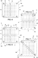
Figures 4-11 are schematic front views of alternative embodiments of the second detail ofFigure 3 ; -
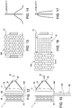
Figure 12 is a schematic side view, with some parts shown in cross-section and some parts removed for the sake of clarity, of a second detail of the light fixture ofFigure 1 in a first operating position; -
Figure 13 is a schematic front view, with some parts removed for the sake of clarity, of the second detail ofFigure 12 ; -
Figure 14 is a schematic diagram of the luminosity of the beam emitted by the light fixture in the operating configuration ofFigure 12 ; -
Figure 15 is a schematic side view, with some parts shown in cross-section and some parts removed for the sake of clarity, of the second detail ofFigure 12 in a second operating position; -
Figure 16 is a schematic front view, with some parts removed for the sake of clarity, of the second detail ofFigure 15 ; -
Figure 17 is a schematic diagram of the luminosity of the beam emitted by the light fixture in the operating configuration ofFigure 15 ; -
Figure 18 is a schematic side view, with some parts shown in cross-section and some parts removed for the sake of clarity, of the second detail ofFigure 15 according to an alternative embodiment; -
Figure 19 is a schematic front view, with some parts removed for the sake of clarity, of the second detail ofFigure 18 ; -
Figure 20 is a schematic diagram of the luminosity of the beam emitted by the light fixture in the operating configuration ofFigure 18 ; -
Figure 21 is a schematic front view of a further detail of the light fixture ofFigure 12 according to an alternative embodiment. - In
Figure 1 reference numeral 1 indicates a light fixture, preferably for stage. - The
light fixture 1 comprises acasing 2 and supporting means (not illustrated in the accompanying figures) configured to support thecasing 2. The supporting means are preferably configured to move thecasing 2 and to allow thecasing 2 to rotate about two orthogonal axes, commonly known as PAN and TILT. The operation of the supporting means is controlled by a movement control device (not visible in the accompanying figures). The movement control device may also be managed remotely preferably using the DMX communication protocol. According to an alternative embodiment, the supporting means may be configured just to support thecasing 2 without being able to move it. - The
casing 2 extends along a longitudinal axis A and is provided with a first closed end 4 and asecond end 5, opposite the first closed end 4 along the axis A, and provided with aprojection hole 6. In the non-limiting example described and illustrated herein, theprojection hole 6 has a substantially circular cross-section. Theprojection hole 6 is preferably centred on the axis A of thecasing 2. - The
light fixture 1 further comprises a frame (not visible in the accompanying figures) coupled to thecasing 2, asource assembly 10 and at least a firstoptical assembly 11. - In the non-limiting example described and illustrated herein, the
light fixture 1 additionally comprises acolour assembly 14, arranged between thesource assembly 10 and the firstoptical assembly 11, beam processing means 15 and at least a secondoptical assembly 16 arranged downstream of the beam processing means 15. - The
source assembly 10, the firstoptical assembly 11, thecolour assembly 14, the beam processing means 15 and the secondoptical assembly 16 are all schematically illustrated inFigure 1 . - The frame is integral with the
casing 2 and comprises a plurality of elements coupled to one another and configured to define a supporting structure for the components arranged inside thecasing 2, namely thesource assembly 10, the firstoptical assembly 11, thecolour assembly 14, the beam processing means 15 and the secondoptical assembly 16. - The
colour assembly 14 comprises at least one colour device configured to selectively colour the incident light beam. Thecolour assembly 14 preferably comprises four different colour devices, in which each colour device comprises one or more filters having specific characteristics. The colour devices thus differ for the filtering characteristics of the filters they contain. - The beam processing means 15 comprise a plurality of light beam processing elements supported by the frame and configured to process the light beam generated by the
source assembly 10 in order to obtain specific effects. In particular, the beam processing elements are supported and/or configured so as to selectively intercept the light beam in order to only modify the light beam when needed. In other words, the beam processing elements can only intercept the beam to alter its properties when needed. - The position of each of the beam processing elements is regulated by a beam processing means control device (not visible in the accompanying figures). The beam processing element control device may also be managed remotely preferably using the DMX communication protocol.
- The beam processing means 15 comprise, preferably in sequence, a first gobo device, a rainbow device, a second gobo device, a frost assembly and a prismatic element (not illustrated in the accompanying figures for the sake of simplicity).
- It is understood that the beam processing means 15 may comprise additional beam processing elements that are not listed here.
- The
source assembly 10 is arranged inside thecasing 2 at the closed end 4 of thecasing 2, it is supported by the frame, and comprises, in the non-limiting example described and illustrated herein, a plurality of light sources 18 (schematically illustrated as a single block inFigure 1 ) suitable to emit light beams mainly along an emission direction B, acollimator assembly 20 and acooling device 21 configured to cool the light sources 18 (schematically illustrated inFigure 1 only). According to an alternative embodiment that is not illustrated, the source assembly only comprises one main light source, for example a discharge lamp. - Emission direction means the direction towards which the greatest amount of the light beam emitted by the
light sources 18 of thesource assembly 10 propagates. In particular, since thesource assembly 10 comprisesseveral light sources 18, the emission direction is determined by considering the main axis of the sum of the light beams emitted by thelight sources 18 which, as described in detail later on in this document, are processed so as to generate a single light beam along an optical axis O. - In the non-limiting example described and illustrated herein, the
source assembly 10 comprises a plurality oflight sources 18 coupled to a flat supportingplate 19 visible inFigures 2-11 . The supportingplate 19 is coupled, in use, to the frame of thelight fixture 1. - Preferably, the
light sources 18 are uniformly distributed in such a way as to generate a plurality of substantially uniformly distributed beams. - The
light sources 18 are preferably arranged on a same plane defined by the supportingplate 19 and are substantially arranged as a matrix. In other words, thelight sources 18 are arranged along horizontal rows and vertical columns. - Preferably, the matrix of
light sources 18 is centred on the longitudinal axis A of thecasing 2. - According to an alternative embodiment that is not illustrated, the light sources are arranged symmetrically with respect to at least one plane of symmetry.
- According to a further alternative embodiment that is not illustrated, the light sources are substantially arranged as a matrix provided with an even number of columns and are symmetrical with respect to a plane arranged between the innermost columns.
- According to a further alternative embodiment that is not illustrated, the light sources are substantially arranged as a matrix provided with an odd number of columns and are symmetrical with respect to a plane that passes through the innermost column. With reference to
Figure 2 , thecollimator assembly 20 is arranged downstream of the light sources along the emission direction B so as to intercept the light beam emitted by thelight sources 18 and is configured to straighten the incoming light beams. In particular, thecollimator assembly 20 comprises a plurality of lenses 22 (schematically illustrated inFigure 2 ), each of which is configured to straighten a respective beam emitted by a respectivelight source 18. - In the case in which the
source assembly 10 comprises a single light source, the collimator assembly 12 comprises a reflector, preferably parabolic, coupled to the light source and configured in such a way as to transform the light beam emitted by the light source into a beam of substantially parallel light rays. In this case the collimator assembly 12 is not arranged downstream of thesource assembly 10. - With reference to
Figure 3 , a group S made up of nlight sources 18 of the plurality oflight sources 18 has the same polygonal shape and is configured in such a way that each light source in the group S is rotated with respect to at least one respective other light source in the group S by an angle α equal to
- R= order of rotational symmetry of the polygon defining the shape of the light sources;
- K= is a coefficient respecting the following condition


- Here and throughout the rest of this document, the order of rotational symmetry R refers to a natural number other than zero such that the rotation about a point O and by an angle equal to 360°/R transforms the figure into its original shape. The point O is called the centre of rotation of the rotational symmetry. Rotational symmetry is also frequently defined as radial symmetry. For example, a square has a rotational symmetry of order 4, a regular polygon has an order of rotational symmetry equal to the number of its sides, while an irregular polygon has a rotational symmetry of
order 1. - In other words, the group S is simply a sub-group of the plurality of light sources 18 (identified in
Figure 3 by means of light sources shown as broken lines) and is composed of light sources all having the same polygonal shape. Eachlight source 18 belonging to this group S is rotated with respect to at least one respective other light source in the same group S by the angle α described above. Essentially, eachlight source 18 belonging to the group S is rotated by an angle α with respect to at least one respective other source in the same group S and is rotated by an angle that is a multiple of α with respect to the other light sources in the group S. - Thanks to the specific configuration described above, it is possible to project a light beam with a substantially circular perimeter profile even when the
light sources 18 have a non-circular polygonal shape. This can be achieved without the use of optical systems to modify or cut the perimeter profile of the light beam. - In the non-limiting example described herein and illustrated in
Figure 3 , the group S comprises a number of sources n equal to 50% of the total number N oflight sources 18. Thelight sources 18 in the group S are all square and are rotated by an angle α equal to 1.8°. - The group S may comprise a variable number n of light sources depending on requirements.
- In particular, as described in detail later on in this document, the shape of the group S, the number and the arrangement of the light sources that make up the group S can be chosen to meet particular requirements in relation to other components of the
light fixture 1 according to the present invention (for instance, in relation to the type of optical mixing element that is used, as we shall see in more detail later on in this document). -
Figures 4-9 show alternative embodiments of the present invention in which the group S oflight sources 18 is defined bylight sources 18 which are rotated and arranged along at least one same row of the matrix (examples inFigures 5 and 6 ), along at least one same column of the matrix (examples inFigures 4 and 6 ) and along at least one same diagonal of the matrix (examples inFigures 7-9 ). - In
Figures 10 and 11 the group S is defined by 100% of thelight sources 18. In other words, in the non-limiting examples illustrated inFigure 10 and Figure 11 , all thelight sources 18 have the same polygonal shape and are each rotated with respect to at least one other according to the above-mentioned relationship (1). - In particular, in the configuration illustrated in
Figure 10 , the matrix has a square profile, whereas in the configuration illustrated inFigure 11 the matrix has a hexagonal profile. - In the non-limiting solutions illustrated in
Figures 4-11 , eachlight source 18 belonging to the group S is preferably rotated by an angle α with respect to the adjacent light source in the same group S. However, said configuration is not necessary in order to achieve the desired optical effect. As already stated, it is in fact sufficient for at least one other light source in the group S to be rotated by an angle α with respect to the source in question. The fact that thelight sources 18 rotated by an angle α are adjacent makes it easier to assemble and position thelight sources 18. - In the examples illustrated in
Figures 3-11 thelight sources 18 all have the same square shape. - It is understood that the shape of the
light sources 18 may be other than square and that thelight sources 18 that do not belong to the group S can also differ from one another in shape and size. - In the non-limiting example described and illustrated herein the
light sources 18 are LED light sources. Preferably, the LEDs that define thelight sources 18 are white. - According to an alternative embodiment that is not illustrated, the
light sources 18 are LEDs of the RGB (red green blue) type. - According to a further alternative embodiment that is not illustrated the
light sources 18 are of the LARP (laser activated remote phosphor) type. For example, each LARP light source comprises a phosphor converter to which a pump laser is coupled. For example, a yellow phosphor converter coupled to a blue laser diode generates a white light. - Alternatively, the LARP light sources can also be coupled to laser diodes of different colours (red, green or blue).
- With reference to
Figure 1 , the firstoptical assembly 11 and the secondoptical assembly 16 are preferably different to one another. - Here and throughout the rest of this document, the term optical assembly refers to an optical assembly capable of altering the direction of at least a portion of the light rays that make up the beam emitted by the
source assembly 10. For example, an optical assembly may comprise at least one lens and/or a group of lenses and/or one or more collimators and/or one or more reflectors and/or one or more prismatic elements and/or one or more mixers and/or one or more condensers. - With reference to
Figure 2 , the firstoptical assembly 11 is arranged downstream of thesource assembly 10 in order to intercept the light beam emitted by thesource assembly 10. - Preferably, the first optical assembly is arranged downstream of the colour assembly 14 (
Figure 1 ). - With reference to
Figure 1 , theoptical assembly 16 is an optical output assembly, arranged at the point furthest downstream along the axis A, so as to be the last assembly able to process the intercepted light beam. Theoptical assembly 16 comprises one or more lenses (not illustrated in the accompanying figures) arranged and configured so that theoptical assembly 16 has a positive refractive power. Theoptical assembly 16 is preferably movable along the axis A to adjust the focus of the projected image. In particular, theoptical assembly 16 is able to move along the axis A between a first operating position and a second operating position. Theoptical assembly 16 preferably comprises a support frame coupled to a carriage which can move along the axis A (not illustrated for the sake of simplicity), the movement of which is regulated by an autofocus device (of a known type and not illustrated). - With reference to
Figure 12 , the firstoptical assembly 11 comprises at least onecondenser device 25, which is configured to concentrate the entering beam in the desired manner and amixing device 26, which is configured to mix the rays of the incoming light beams to generate a mixed and homogeneous light beam. - The mixing
device 26 of the firstoptical assembly 11 is arranged upstream of thecondenser device 25 along the emission direction B of the beam and downstream of thesource assembly 10. - In the non-limiting example described and illustrated herein, the
condenser device 25 comprises alens 27 configured to concentrate the beam in a given plane (called the focal plane) in which there is preferably arranged aprocessing element 28 of the beam processing means 15 (schematically illustrated inFigure 1 ). Thecondenser device 25 is preferably configured to concentrate the light beam in such a way that the beam has a smaller cross-section than the cross-section of the beam entering thecondenser 25 substantially in the region of a focal point in the focal plane. - For example, a gobo disk, or a diaphragm, or other elements of the beam processing means 15 may be positioned in the focal point.
- In the non-limiting example described and illustrated herein, the
lens 27 is a flat convex lens. - According to an alternative embodiment not illustrated herein, the
condenser device 25 is defined by a group of coupled lenses. - Essentially, the light beam leaving the first
optical assembly 11 illustrated inFigure 2 is condensed. In this way, the light beam leaving the firstoptical assembly 11 is a beam with an optical axis O, which in the non-limiting example described and illustrated herein coincides with the longitudinal axis A. - Thanks to the particular arrangement of the
light sources 18 of thesource assembly 10, the light beam leaving the firstoptical assembly 11 has a substantially circular perimeter profile irrespective of the shape of the individuallight sources 18 used. - The mixing
device 26 comprises anoptical mixing element 128 and a moving device 129 (schematically illustrated in the accompanyingFigures 12, 15 and18 ) configured to move theoptical mixing element 128 between a first position of non-interference with the light beam emitted by the source assembly 10 (configuration inFigures 15-17 and18-20 ) and at least a second position of interference with the light beam emitted by the source assembly 10 (configuration inFigures 12-14 ). - Advantageously, in the interference position the mixing
device 26 intercepts and appropriately mixes the light beam. This improves the quality of the projected beam. However, the inclusion of the mixingdevice 26 also results in a loss of luminosity of the projected beam as illustrated inFigure 14 . - In the non-interference position, the luminosity of the beam emitted by the
light fixture 1 is the maximum that can be obtained as illustrated inFigure 17 and inFigure 20 . In this configuration, the light beam is in fact at high intensity. However, in the non-interference position, the quality of the beam is lower than the quality that can be achieved in the interference position, especially if the colour assembly 14 (not illustrated inFigures 2 ,15 and18 ) colours the beam emitted by thesource assembly 10. - Essentially, the first
optical assembly 11 is able to determine an increase in the luminosity or in the quality of the beam according to stage lighting needs. - For example, if the beam has to be projected at a long distance, the first
optical assembly 11 can be adjusted so that the beam generated is characterised by a high level of luminosity (in technical jargon this solution is referred to as a hot spot and can be achieved with theoptical mixing element 128 in the non-interference position), whereas if the beam has to be projected relatively close to thelight fixture 1, the firstoptical assembly 11 can be adjusted so that the beam generated by thelight fixture 1 is characterised by a high level of uniformity (in technical jargon this solution is referred to as a uniform even beam and can be achieved with theoptical mixing element 128 in the interference position). - The
optical mixing element 128 can be switched between the non-interference position and the interference position rapidly to obtain an immediate effect, or gradually, to obtain a gradual dimming effect (when switched from the non-interference position to the interference position) or a gradual increase in luminosity (when switched from the interference position to the non-interference position). - With reference to
Figures 12, 13, 15, 16 ,19 and 21 , theoptical mixing element 128 is preferably an optical element known in the jargon of the field as a fly's-eye optical element, or sometimes as a fly's-eye condenser or fly's-eye mirror. - The
optical mixing element 128 comprises a plurality of lenses arranged side by side so as to form an array. Each lens projects an image proportional to its own shape. The overlapping of the projected images determines a mixing of the light beams emitted by thesource assembly 10. - In
Figures 13, 16 and19 , theoptical mixing element 128 is composed of hexagonal lenses. -
Figure 21 illustrates an alternative embodiment of theoptical mixing element 228. According to this alternative embodiment, theoptical mixing element 228 comprises a plurality oflenses 229 arranged side by side. The plurality oflenses 229 comprise at least twolenses 229 provided with emission faces having a different perimeter shape. - In this way the available surface can be exploited in the best possible way.
- Furthermore, the
optical mixing element 228 comprises aperimeter group 230 oflenses 229a, which are arranged side by side to define a perimeter profile of theoptical mixing element 228. In this way the perimeter profile of theoptical mixing element 228 is defined by theperimeter group 230 and can be modified simply by adjusting the shape of thelenses 229a in theperimeter group 230. - In the non-limiting example described and illustrated herein, the
lenses 229a in theperimeter group 230 have at least one side that is curved, or that approximates a curve, so as to define, when arranged side by side, a substantially circular perimeter profile of theoptical mixing element 228. - In the non-limiting example described and illustrated herein, the plurality of
lenses 229 comprise acentral lens 229d having a hexagonally-shaped emission face, a first group oflenses 229c having an emission face with a pentagonal perimeter and arranged along a first circular path PI, a second group oflenses 229b having an emission face with a pentagonal perimeter and arranged along a second circular path P2 concentric to PI, and theperimeter group 230 composed oflenses 229a having an emission face with a quadrangular or pentagonal perimeter and arranged along a third circular path P3 concentric to P1 and to P2. - In the non-limiting example described herein and illustrated in
Figures 12, 13, 15 and 16 , theoptical mixing element 128 is substantially monolithic and moved by the movingdevice 129 between a first position of non-interference with the light beam emitted by the source assembly 10 (configuration inFigures 15-16 ,18-19 ) and at least a second position of interference with the light beam emitted by the source assembly 10 (configuration inFigures 12-13 ). - According to an alternative embodiment illustrated in
Figures 18 and 19 , theoptical element 128 is divided into a number ofportions 130 which are movable along a direction orthogonal to the emission direction B of the beam. The expression "along a direction orthogonal to the emission direction B of the beam" clearly means any direction in a plane orthogonal to the emission direction B of the beam. - In other words, the
portions 130 are movable along a plane orthogonal to the emission direction B of the beam. - In the non-limiting example described herein and illustrated in
Figure 19 , theoptical mixing element 128 is composed of two substantiallyidentical portions 130 movable along a direction orthogonal to the emission direction B of the beam. - The
source assembly 10 arranged in the light fixture inFigures 12, 13, 15, 16 ,18 and 19 is preferably that illustrated inFigure 10 , in which substantially all of thelight sources 18 belong to the group S of rotated sources. -
Figures 4-9 illustrate alternative embodiments of thesource assembly 10 in which the group S oflight sources 18 is defined bylight sources 18 which are rotated and arranged along at least one same row of the matrix (examples inFigures 4 and 6 ), along at least one same column of the matrix (examples inFigures 5 and 6 ) and along at least one same diagonal of the matrix (examples inFigures 7-9 ). In the case of thelight sources 10 illustrated inFigures 4-9 , optical mixingelements 128 similar to and/or different from the one illustrated inFigures 13 and19 can be used. - In the cases illustrated in
Figures 4-9 , the number n oflight sources 18 that make up the group S and their arrangement depend on the type ofoptical mixing element 128 that is used. In particular, the number n and the arrangement of the light sources that make up the group S depend on the shape and on the arrangement of the portion of the matrix oflight sources 18 left uncovered during the movement of theoptical mixing element 128. Essentially, the number n oflight sources 18 that make up the group S and their arrangement is chosen in such a way that when theoptical mixing element 128 moves towards the position of non-interference thesource assembly 10 still emits a light beam with a substantially circular profile thanks to the particular arrangement of thelight sources 18 in the group S. - In particular, in
Figure 4 theoptical mixing element 128 illustrated by means of a broken line is substantially identical to that shown inFigure 19 . InFigure 5 , on the other hand, theoptical mixing element 128 illustrated by means of a broken line is substantially identical to that shown inFigure 19 in that it is divided into two substantiallyidentical portions 130 but is movable along a direction orthogonal to the direction along which theoptical mixing element 128 shown inFigure 4 is movable, to selectively intercept the light beam. - Also in the configurations illustrated in
Figures 7 and8 , theoptical mixing element 128 illustrated by means of a broken line is divided into two substantiallyidentical portions 130 that are movable to selectively intercept the light beam. - Essentially, in the configurations in
Figures 4, 5, 7 and8 , theoptical mixing element 128 is divided into two substantiallyidentical portions 130 that are movable along a direction substantially orthogonal to the emission direction B of the beam and orthogonal to the line separating the twoportions 130 to selectively intercept the light beam. - In the solutions illustrated in
Figures 6 and9 , theoptical mixing element 128 is divided into 4 substantially identical parts that are movable to selectively intercept the light beam. - In the configuration in
Figure 6 , the fourparts 130 have a four-sided shape and are able to move, as required, along a same direction substantially orthogonal to the emission direction B of the beam or along at least two directions orthogonal to one another and orthogonal to the emission direction B of the beam. - In the configuration in
Figure 9 , the fourparts 130 are triangular and are able to move along at least two directions orthogonal to one another and orthogonal to the emission direction B of the beam. - The movement of the
portions 130 illustrated in the configurations inFigures 4-9 and19 is preferably simultaneous and regulated by the movingdevice 129. In the configurations inFigures 4-9 and19 , the simultaneous movement is also symmetrical. - According to an alternative embodiment that is not illustrated, each
portion 130 can move independently. - The moving
device 129 may comprise one or more motors to move theoptical mixing element 128 and the related motion transmission devices (not illustrated in the accompanying figures for the sake of simplicity). - The moving
device 129 is regulated by means of a control device (not visible in the accompanying figures). The control device of the movingdevice 129 may also be managed remotely preferably by means of one or more external signals received, for example, using the DMX communication protocol. - Advantageously, the control device can adjust the moving
device 129 in order to obtain a variation in the intensity of the light beam. - As shown in
Figures 14, 17 and20 , adjusting the position of theoptical mixing element 128 affects the intensity of the light beam projected by thelight fixture 1. Thus, adjusting the position of theoptical mixing element 128 adjusts the intensity of the light beam. - Advantageously, the luminosity of the
source assembly 10 can be adjusted according to the operating position of theoptical element 128. In particular, the light fixture comprises a control device of the source assembly 10 (not illustrated), which is configured to regulate the luminosity of eachlight source 18 or of one or more groups oflight sources 18, based on the operating position of theoptical element 128. For example, the control device of thesource assembly 10 can regulate the luminosity of eachlight source 18 or of one or more groups oflight sources 18 according to the degree of interference of theoptical element 128 with the light beam and/or according to the movement and positions of themovable portions 130 of theoptical element 128. - Lastly, it is clear that modifications and variations may be made to the source assembly and to the light fixture described herein without departing from the scope of the appended claims.
Claims (17)
- Light fixture, preferably for stage, comprising:a source assembly (10) configured to generate a light beam mainly along an emission direction (B);at least one optical assembly (11) arranged downstream of the source assembly (10) along the emission direction (B);the first optical assembly (11) comprising at least one mixing device (26) configured to mix the light beam passing through it; the mixing device (26) comprising an optical mixing element (128) and a moving device (129) configured to move the optical mixing element (128) between a position of non-interference with the light beam emitted by the source assembly (10) and at least one position of interference with the light beam emitted by the source assembly (10).
- Light fixture according to claim 1, wherein the optical assembly (11) comprises at least one condenser device (25), which is configured to concentrate the entering light beam in a plane; the mixing device (26) being arranged upstream of the condenser device (25) along the emission direction (B) of the beam.
- Light fixture according to claim 1 or 2, wherein the optical mixing element (128) is divided into at least two portions (130) which are movable to selectively interfere with the light beam.
- Light fixture according to claim 3, wherein the portions (130) are movable along a direction substantially orthogonal to the emission direction (B) of the light beam.
- Light fixture according to claim 3 or 4, wherein the portions (130) are movable along a direction substantially orthogonal to the line separating the two portions (130).
- Light fixture according to claim 3, wherein the optical mixing element (128) is divided into at least four portions (130).
- Light fixture according to any one of claims 3 to 6, wherein the moving device (129) is configured to move the portions (130) simultaneously.
- Light fixture according to any one of the preceding claims, comprising at least one control device of the moving device (129) configured to regulate the moving device (129) on the basis of at least one external signal.
- Light fixture according to any one of the preceding claims, wherein the optical mixing element (128) is a fly's-eye optical element.
- Light fixture according to any one of the preceding claims, wherein the source assembly (10) comprises a supporting plate (19) and a plurality of polygonal light sources (18) coupled to the supporting plate (19) and configured to emit respective light beams mainly along the emission direction (B); wherein the plurality of light sources (18) comprise a group (S) made of a number (n) of light sources (18) having the same polygonal shape; each light source (18) in the group (S) being rotated with respect to at least another light source (18) in the group (S) by an angle (α) equal to
 R= order of rotational symmetry of the polygon defining the shape of the light sources (18);K= is a coefficient respecting the following conditions

- Light fixture according to claim 9, wherein the number (n) of light sources (18) defining the group (S) is equal to at least 10% of the total number (N) of the plurality of light sources (18).
- Light fixture according to claim 9, wherein the number (n) of light sources (18) defining the group (S) is equal to at least 50% of the total number (N) of the plurality of light sources (18).
- Light fixture according to any one of claims 9 to 11, wherein the light sources (18) of the plurality of light sources (18) are arranged according to a matrix provided with a plurality of rows and columns; the group (S) being defined by light sources (18) arranged along at least one same row and/or along at least one same column and/or along at least one same diagonal of the matrix.
- Light fixture according to any one of claims 9 to 12, wherein each light source (18) in the group (S) is rotated by the angle (α) with respect to the adjacent light source (18).
- Light fixture according to any one of the preceding claims, wherein the source assembly (10) comprises a supporting plate (19) and a plurality of polygonal light sources (18) coupled to the supporting plate (19) and configured to emit respective light beams mainly along the emission direction (B); the light sources (18) are arranged symmetrically with respect to at least one plane of symmetry.
- Light fixture according claim 15, wherein the light sources (18) of the plurality of light sources (18) are arranged according to a matrix provided with a plurality of rows and columns; if the matrix has an even number of columns, the light sources (18) are symmetrical with respect to a plane arranged between the innermost columns, whereas if the matrix has an odd number of columns, the light sources (18) are symmetrical with respect to a plane passing through the innermost column.
- Light fixture according to any one of the preceding claims, comprising a control device of the light source assembly (10) configured to regulate the luminosity of the source assembly (10) based on the operating position of the optical element (128).
Applications Claiming Priority (1)
| Application Number | Priority Date | Filing Date | Title |
|---|---|---|---|
| IT102017000120670A IT201700120670A1 (en) | 2017-10-24 | 2017-10-24 | HEADLAMP, PREFERABLY FROM STAGE |
Publications (1)
| Publication Number | Publication Date |
|---|---|
| EP3477191A1 true EP3477191A1 (en) | 2019-05-01 |
Family
ID=61224428
Family Applications (1)
| Application Number | Title | Priority Date | Filing Date |
|---|---|---|---|
| EP18202418.2A Withdrawn EP3477191A1 (en) | 2017-10-24 | 2018-10-24 | Light fixture, preferably for stage |
Country Status (4)
| Country | Link |
|---|---|
| US (1) | US10914439B2 (en) |
| EP (1) | EP3477191A1 (en) |
| CN (1) | CN109695851B (en) |
| IT (1) | IT201700120670A1 (en) |
Families Citing this family (9)
| Publication number | Priority date | Publication date | Assignee | Title |
|---|---|---|---|---|
| WO2019145405A1 (en) * | 2018-01-25 | 2019-08-01 | Lego A/S | Toy construction system with robotics control unit |
| EP3557126B1 (en) * | 2018-04-20 | 2024-03-13 | Insolight SA | Optomechanical system and method for controlling the photometric distribution of luminaires and corresponding luminaires |
| JP7267761B2 (en) * | 2019-01-31 | 2023-05-02 | キヤノン株式会社 | Light source device, illumination device, exposure device, and method for manufacturing article |
| CN112815272B (en) * | 2019-11-18 | 2023-10-10 | 深圳市绎立锐光科技开发有限公司 | Light source systems and lighting equipment |
| EP4080112B1 (en) * | 2021-04-22 | 2026-07-29 | Harman Professional Denmark ApS | Illumination device with light source emulation effect |
| CN113531441B (en) * | 2021-08-04 | 2022-04-22 | 广州光联电子科技有限公司 | Light source system |
| CN114017751B (en) * | 2021-11-25 | 2023-12-05 | 闽都创新实验室 | LED insect trap lamp with high illuminance uniformity and design method thereof |
| USD1067489S1 (en) | 2022-11-23 | 2025-03-18 | Harman International Industries, Incorporated | Lighting device with light pattern |
| CN116594245A (en) * | 2023-06-28 | 2023-08-15 | 深圳市神牛摄影器材有限公司 | Video panel light |
Citations (9)
| Publication number | Priority date | Publication date | Assignee | Title |
|---|---|---|---|---|
| EP2211089A1 (en) * | 2009-01-26 | 2010-07-28 | GLP German Light Products GmbH | Apparatus and method for outputting a mixed-colored light beam |
| US20120155102A1 (en) * | 2009-08-20 | 2012-06-21 | Erwin Melzner | Led luminaire, particularly led headlight |
| WO2013014809A1 (en) * | 2011-07-27 | 2013-01-31 | コニカミノルタアドバンストレイヤー株式会社 | Led illumination device and optical element |
| WO2013142434A2 (en) * | 2012-03-18 | 2013-09-26 | Robe Lighting, Inc. | Zoom optical system for an automated luminaire |
| WO2014031644A1 (en) * | 2012-08-20 | 2014-02-27 | Robe Lighting, Inc. | Improved diffusion system for an automated luminaire |
| US20150036354A1 (en) * | 2013-08-02 | 2015-02-05 | Stephen P. Adams | Method and apparatus for a light collection and projection system |
| US20150092422A1 (en) * | 2013-10-01 | 2015-04-02 | Pavel Jurik | Heat protection and homogenizing system for a luminaire utilizing a lamp with an intense hotspot |
| EP2881651A1 (en) * | 2013-12-05 | 2015-06-10 | Martin Professional ApS | Projecting light fixture with a plurality of lenslets packed in an optimized dense circular pattern |
| WO2017092665A1 (en) * | 2015-11-30 | 2017-06-08 | 深圳市光峰光电技术有限公司 | Lighting device |
Family Cites Families (9)
| Publication number | Priority date | Publication date | Assignee | Title |
|---|---|---|---|---|
| US7725024B2 (en) * | 2005-07-08 | 2010-05-25 | Electro Scientific Industries, Inc. | Optimizing use and performance of optical systems implemented with telecentric on-axis dark field illumination |
| DE102006047233A1 (en) * | 2006-10-04 | 2008-04-10 | Osram Opto Semiconductors Gmbh | Optical element for a light-emitting diode, light-emitting diode, LED arrangement and method for producing an LED arrangement |
| US7682042B2 (en) * | 2008-04-23 | 2010-03-23 | Designs For Vision, Inc. | Illumination device |
| CN101852348B (en) * | 2009-04-03 | 2013-04-24 | 富士迈半导体精密工业(上海)有限公司 | Illumination system |
| US8985793B2 (en) * | 2010-08-02 | 2015-03-24 | Sharp Kabushiki Kaisha | Illumination device |
| EP2718620B1 (en) * | 2011-06-10 | 2016-12-14 | Martin Professional A/S | Multi-mode illumination device |
| ITMI20131386A1 (en) * | 2013-08-12 | 2015-02-13 | Clay Paky Spa | STAGE PROJECTOR |
| US10197244B2 (en) * | 2014-03-12 | 2019-02-05 | Clay Paky S.P.A. | Stage light fixture |
| CN106871066A (en) * | 2017-02-21 | 2017-06-20 | 黄建芳 | A kind of stage lighting optical system for changing light distribution in real time |
-
2017
- 2017-10-24 IT IT102017000120670A patent/IT201700120670A1/en unknown
-
2018
- 2018-10-22 US US16/166,760 patent/US10914439B2/en active Active
- 2018-10-23 CN CN201811236652.XA patent/CN109695851B/en active Active
- 2018-10-24 EP EP18202418.2A patent/EP3477191A1/en not_active Withdrawn
Patent Citations (10)
| Publication number | Priority date | Publication date | Assignee | Title |
|---|---|---|---|---|
| EP2211089A1 (en) * | 2009-01-26 | 2010-07-28 | GLP German Light Products GmbH | Apparatus and method for outputting a mixed-colored light beam |
| US20100188018A1 (en) * | 2009-01-26 | 2010-07-29 | Glp German Light Products Gmbh | Spotlight and method of lighting up an object |
| US20120155102A1 (en) * | 2009-08-20 | 2012-06-21 | Erwin Melzner | Led luminaire, particularly led headlight |
| WO2013014809A1 (en) * | 2011-07-27 | 2013-01-31 | コニカミノルタアドバンストレイヤー株式会社 | Led illumination device and optical element |
| WO2013142434A2 (en) * | 2012-03-18 | 2013-09-26 | Robe Lighting, Inc. | Zoom optical system for an automated luminaire |
| WO2014031644A1 (en) * | 2012-08-20 | 2014-02-27 | Robe Lighting, Inc. | Improved diffusion system for an automated luminaire |
| US20150036354A1 (en) * | 2013-08-02 | 2015-02-05 | Stephen P. Adams | Method and apparatus for a light collection and projection system |
| US20150092422A1 (en) * | 2013-10-01 | 2015-04-02 | Pavel Jurik | Heat protection and homogenizing system for a luminaire utilizing a lamp with an intense hotspot |
| EP2881651A1 (en) * | 2013-12-05 | 2015-06-10 | Martin Professional ApS | Projecting light fixture with a plurality of lenslets packed in an optimized dense circular pattern |
| WO2017092665A1 (en) * | 2015-11-30 | 2017-06-08 | 深圳市光峰光电技术有限公司 | Lighting device |
Also Published As
| Publication number | Publication date |
|---|---|
| IT201700120670A1 (en) | 2019-04-24 |
| US10914439B2 (en) | 2021-02-09 |
| CN109695851B (en) | 2022-08-02 |
| US20190120447A1 (en) | 2019-04-25 |
| CN109695851A (en) | 2019-04-30 |
Similar Documents
| Publication | Publication Date | Title |
|---|---|---|
| US10914439B2 (en) | Light fixture, preferably for stage | |
| US10386030B2 (en) | Light fixture, preferably for stage | |
| RU2608541C2 (en) | Local lighting device | |
| US10520175B2 (en) | Collimation and homogenization system for an LED luminaire | |
| US10408402B2 (en) | Optical system for a LED luminaire | |
| US10371956B2 (en) | Homogenization system for an LED luminaire | |
| EP2920507B1 (en) | Luminaire with articulated elongated light beam homogenizer | |
| WO2015138483A2 (en) | Optical system for an led luminaire | |
| EP3715704B1 (en) | Homogenization system for an led luminaire | |
| US10197244B2 (en) | Stage light fixture | |
| EP4180711B1 (en) | Homogenization of an led array | |
| EP2810121B1 (en) | An improved light collimation system | |
| CN107526129B (en) | Light irradiation device and optical fiber path used for the same | |
| EP4372446A1 (en) | Light fixture for generating high-visibility light beams at long distance | |
| CN109312902B (en) | Dyeing light illuminating device with special effect function | |
| EP3715703B1 (en) | Light fixture, preferably for stage, and method for operating said light fixture | |
| WO2017165685A1 (en) | Optical system for an led luminaire |
Legal Events
| Date | Code | Title | Description |
|---|---|---|---|
| PUAI | Public reference made under article 153(3) epc to a published international application that has entered the european phase |
Free format text: ORIGINAL CODE: 0009012 |
|
| STAA | Information on the status of an ep patent application or granted ep patent |
Free format text: STATUS: THE APPLICATION HAS BEEN PUBLISHED |
|
| AK | Designated contracting states |
Kind code of ref document: A1 Designated state(s): AL AT BE BG CH CY CZ DE DK EE ES FI FR GB GR HR HU IE IS IT LI LT LU LV MC MK MT NL NO PL PT RO RS SE SI SK SM TR |
|
| AX | Request for extension of the european patent |
Extension state: BA ME |
|
| STAA | Information on the status of an ep patent application or granted ep patent |
Free format text: STATUS: REQUEST FOR EXAMINATION WAS MADE |
|
| 17P | Request for examination filed |
Effective date: 20191030 |
|
| RBV | Designated contracting states (corrected) |
Designated state(s): AL AT BE BG CH CY CZ DE DK EE ES FI FR GB GR HR HU IE IS IT LI LT LU LV MC MK MT NL NO PL PT RO RS SE SI SK SM TR |
|
| STAA | Information on the status of an ep patent application or granted ep patent |
Free format text: STATUS: EXAMINATION IS IN PROGRESS |
|
| 17Q | First examination report despatched |
Effective date: 20200924 |
|
| RAP1 | Party data changed (applicant data changed or rights of an application transferred) |
Owner name: OSRAM GMBH Owner name: CLAY PAKY S.P.A. |
|
| RAP1 | Party data changed (applicant data changed or rights of an application transferred) |
Owner name: CLAY PAKY S.P.A. |
|
| P01 | Opt-out of the competence of the unified patent court (upc) registered |
Effective date: 20230525 |
|
| RAP1 | Party data changed (applicant data changed or rights of an application transferred) |
Owner name: CLAY PAKY S.R.L. |
|
| STAA | Information on the status of an ep patent application or granted ep patent |
Free format text: STATUS: THE APPLICATION IS DEEMED TO BE WITHDRAWN |
|
| 18D | Application deemed to be withdrawn |
Effective date: 20240223 |