EP3477088A1 - Apparatus and methods for controlling reciprocating internal combustion engines - Google Patents
Apparatus and methods for controlling reciprocating internal combustion engines Download PDFInfo
- Publication number
- EP3477088A1 EP3477088A1 EP18196287.9A EP18196287A EP3477088A1 EP 3477088 A1 EP3477088 A1 EP 3477088A1 EP 18196287 A EP18196287 A EP 18196287A EP 3477088 A1 EP3477088 A1 EP 3477088A1
- Authority
- EP
- European Patent Office
- Prior art keywords
- cavity
- fuel
- piston
- internal combustion
- reciprocating internal
- Prior art date
- Legal status (The legal status is an assumption and is not a legal conclusion. Google has not performed a legal analysis and makes no representation as to the accuracy of the status listed.)
- Granted
Links
Images





Classifications
-
- F—MECHANICAL ENGINEERING; LIGHTING; HEATING; WEAPONS; BLASTING
- F01—MACHINES OR ENGINES IN GENERAL; ENGINE PLANTS IN GENERAL; STEAM ENGINES
- F01B—MACHINES OR ENGINES, IN GENERAL OR OF POSITIVE-DISPLACEMENT TYPE, e.g. STEAM ENGINES
- F01B17/00—Reciprocating-piston machines or engines characterised by use of uniflow principle
- F01B17/02—Engines
- F01B17/025—Engines using liquid air
-
- F—MECHANICAL ENGINEERING; LIGHTING; HEATING; WEAPONS; BLASTING
- F02—COMBUSTION ENGINES; HOT-GAS OR COMBUSTION-PRODUCT ENGINE PLANTS
- F02M—SUPPLYING COMBUSTION ENGINES IN GENERAL WITH COMBUSTIBLE MIXTURES OR CONSTITUENTS THEREOF
- F02M23/00—Apparatus for adding secondary air to fuel-air mixture
-
- F—MECHANICAL ENGINEERING; LIGHTING; HEATING; WEAPONS; BLASTING
- F01—MACHINES OR ENGINES IN GENERAL; ENGINE PLANTS IN GENERAL; STEAM ENGINES
- F01K—STEAM ENGINE PLANTS; STEAM ACCUMULATORS; ENGINE PLANTS NOT OTHERWISE PROVIDED FOR; ENGINES USING SPECIAL WORKING FLUIDS OR CYCLES
- F01K25/00—Plants or engines characterised by use of special working fluids, not otherwise provided for; Plants operating in closed cycles and not otherwise provided for
- F01K25/06—Plants or engines characterised by use of special working fluids, not otherwise provided for; Plants operating in closed cycles and not otherwise provided for using mixtures of different fluids
-
- F—MECHANICAL ENGINEERING; LIGHTING; HEATING; WEAPONS; BLASTING
- F01—MACHINES OR ENGINES IN GENERAL; ENGINE PLANTS IN GENERAL; STEAM ENGINES
- F01L—CYCLICALLY OPERATING VALVES FOR MACHINES OR ENGINES
- F01L1/00—Valve-gear or valve arrangements, e.g. lift-valve gear
- F01L1/36—Valve-gear or valve arrangements, e.g. lift-valve gear peculiar to machines or engines of specific type other than four-stroke cycle
- F01L1/38—Valve-gear or valve arrangements, e.g. lift-valve gear peculiar to machines or engines of specific type other than four-stroke cycle for engines with other than four-stroke cycle, e.g. with two-stroke cycle
-
- F—MECHANICAL ENGINEERING; LIGHTING; HEATING; WEAPONS; BLASTING
- F02—COMBUSTION ENGINES; HOT-GAS OR COMBUSTION-PRODUCT ENGINE PLANTS
- F02B—INTERNAL-COMBUSTION PISTON ENGINES; COMBUSTION ENGINES IN GENERAL
- F02B1/00—Engines characterised by fuel-air mixture compression
- F02B1/02—Engines characterised by fuel-air mixture compression with positive ignition
- F02B1/08—Engines characterised by fuel-air mixture compression with positive ignition with separate admission of air and fuel into cylinder
- F02B1/10—Methods of operating
-
- F—MECHANICAL ENGINEERING; LIGHTING; HEATING; WEAPONS; BLASTING
- F02—COMBUSTION ENGINES; HOT-GAS OR COMBUSTION-PRODUCT ENGINE PLANTS
- F02B—INTERNAL-COMBUSTION PISTON ENGINES; COMBUSTION ENGINES IN GENERAL
- F02B1/00—Engines characterised by fuel-air mixture compression
- F02B1/12—Engines characterised by fuel-air mixture compression with compression ignition
- F02B1/14—Methods of operating
-
- F—MECHANICAL ENGINEERING; LIGHTING; HEATING; WEAPONS; BLASTING
- F02—COMBUSTION ENGINES; HOT-GAS OR COMBUSTION-PRODUCT ENGINE PLANTS
- F02B—INTERNAL-COMBUSTION PISTON ENGINES; COMBUSTION ENGINES IN GENERAL
- F02B75/00—Other engines
- F02B75/02—Engines characterised by their cycles, e.g. six-stroke
-
- F—MECHANICAL ENGINEERING; LIGHTING; HEATING; WEAPONS; BLASTING
- F02—COMBUSTION ENGINES; HOT-GAS OR COMBUSTION-PRODUCT ENGINE PLANTS
- F02M—SUPPLYING COMBUSTION ENGINES IN GENERAL WITH COMBUSTIBLE MIXTURES OR CONSTITUENTS THEREOF
- F02M25/00—Engine-pertinent apparatus for adding non-fuel substances or small quantities of secondary fuel to combustion-air, main fuel or fuel-air mixture
-
- F—MECHANICAL ENGINEERING; LIGHTING; HEATING; WEAPONS; BLASTING
- F02—COMBUSTION ENGINES; HOT-GAS OR COMBUSTION-PRODUCT ENGINE PLANTS
- F02M—SUPPLYING COMBUSTION ENGINES IN GENERAL WITH COMBUSTIBLE MIXTURES OR CONSTITUENTS THEREOF
- F02M31/00—Apparatus for thermally treating combustion-air, fuel, or fuel-air mixture
-
- F—MECHANICAL ENGINEERING; LIGHTING; HEATING; WEAPONS; BLASTING
- F02—COMBUSTION ENGINES; HOT-GAS OR COMBUSTION-PRODUCT ENGINE PLANTS
- F02B—INTERNAL-COMBUSTION PISTON ENGINES; COMBUSTION ENGINES IN GENERAL
- F02B75/00—Other engines
- F02B75/02—Engines characterised by their cycles, e.g. six-stroke
- F02B2075/022—Engines characterised by their cycles, e.g. six-stroke having less than six strokes per cycle
- F02B2075/028—Engines characterised by their cycles, e.g. six-stroke having less than six strokes per cycle five
-
- F—MECHANICAL ENGINEERING; LIGHTING; HEATING; WEAPONS; BLASTING
- F02—COMBUSTION ENGINES; HOT-GAS OR COMBUSTION-PRODUCT ENGINE PLANTS
- F02M—SUPPLYING COMBUSTION ENGINES IN GENERAL WITH COMBUSTIBLE MIXTURES OR CONSTITUENTS THEREOF
- F02M23/00—Apparatus for adding secondary air to fuel-air mixture
- F02M2023/008—Apparatus for adding secondary air to fuel-air mixture by injecting compressed air directly into the combustion chamber
-
- F—MECHANICAL ENGINEERING; LIGHTING; HEATING; WEAPONS; BLASTING
- F02—COMBUSTION ENGINES; HOT-GAS OR COMBUSTION-PRODUCT ENGINE PLANTS
- F02M—SUPPLYING COMBUSTION ENGINES IN GENERAL WITH COMBUSTIBLE MIXTURES OR CONSTITUENTS THEREOF
- F02M2700/00—Supplying, feeding or preparing air, fuel, fuel air mixtures or auxiliary fluids for a combustion engine; Use of exhaust gas; Compressors for piston engines
- F02M2700/43—Arrangements for supplying air, fuel or auxiliary fluids to a combustion space of mixture compressing engines working with liquid fuel
-
- Y—GENERAL TAGGING OF NEW TECHNOLOGICAL DEVELOPMENTS; GENERAL TAGGING OF CROSS-SECTIONAL TECHNOLOGIES SPANNING OVER SEVERAL SECTIONS OF THE IPC; TECHNICAL SUBJECTS COVERED BY FORMER USPC CROSS-REFERENCE ART COLLECTIONS [XRACs] AND DIGESTS
- Y02—TECHNOLOGIES OR APPLICATIONS FOR MITIGATION OR ADAPTATION AGAINST CLIMATE CHANGE
- Y02T—CLIMATE CHANGE MITIGATION TECHNOLOGIES RELATED TO TRANSPORTATION
- Y02T10/00—Road transport of goods or passengers
- Y02T10/10—Internal combustion engine [ICE] based vehicles
- Y02T10/12—Improving ICE efficiencies
Definitions
- the present disclosure concerns apparatus and methods for controlling reciprocating internal combustion engines.
- Reciprocating internal combustion engines usually include one or more cylinders which define a cavity, and a piston moveable within the cavity of the cylinder.
- a hydrocarbon fuel such as diesel or petroleum
- the pressure generated by the combustion of the hydrocarbon fuel causes the piston to move reciprocally within the cylinder and rotate a crankshaft.
- a method of controlling a reciprocating internal combustion engine comprising: a cylinder defining a cavity having a first end and a second end; and a piston moveable within the cavity of the cylinder between the first end and the second end, the method comprising: receiving at least a first signal; determining a quantity of liquid air to be injected using at least the received first signal; controlling injection of the determined quantity of liquid air into the first end of the cavity at a first time when the piston is closer to the first end than the second end.
- the first signal may include user input data defining the fuel.
- the first signal may include data defining one or more properties of the fuel.
- the one or more properties may include a combustion property of the fuel.
- the first signal may include data defining an operating parameter of the reciprocating internal combustion engine.
- the method may further comprise controlling injection of fuel into the first end of the cavity to cause the piston to perform a power stroke.
- the determined quantity of liquid air may be injected into the first end of the cavity without fuel to cause the piston to perform a first power stroke.
- the method may further comprise controlling injection of fuel into the first end of the cavity at a second time when the piston is closer to the first end than the second end to cause the piston to perform a second power stroke.
- the method may further comprise controlling injection of fuel into the first end of the cavity at a third time when the piston is closer to the first end than the second end to cause the piston to perform an initial power stroke, the third time being prior to the first time.
- the liquid air may have greater oxygen content than atmospheric air.
- a non-transitory computer readable storage medium comprising computer readable instructions that, when read by a computer, cause performance of the method as described in the preceding paragraphs.
- apparatus for controlling a reciprocating internal combustion engine comprising: a cylinder defining a cavity having a first end and a second end; and a piston moveable within the cavity of the cylinder between the first end and the second end, the apparatus comprising a controller configured to: receive at least a first signal; determine a quantity of liquid air to be injected using at least the received first signal; control injection of the determined quantity of liquid air into the first end of the cavity at a first time when the piston is closer to the first end than the second end.
- the first signal may include user input data defining the fuel.
- the first signal may include data defining one or more properties of the fuel.
- the one or more properties may include a combustion property of the fuel.
- the first signal may include data defining an operating parameter of the reciprocating internal combustion engine.
- the controller may be configured to control injection of fuel into the first end of the cavity to cause the piston to perform a power stroke.
- the determined quantity of liquid air may be injected into the first end of the cavity without fuel to cause the piston to perform a first power stroke.
- the controller may be configured to control injection of fuel into the first end of the cavity at a second time when the piston is closer to the first end than the second end to cause the piston to perform a second power stroke.
- the controller may be configured to control injection of fuel into the first end of the cavity at a third time when the piston is closer to the first end than the second end to cause the piston to perform an initial power stroke, the third time being prior to the first time.
- the liquid air may have greater oxygen content than atmospheric air.
- Fig. 1 illustrates a schematic diagram of apparatus 10 for controlling a reciprocating internal combustion engine 12.
- the apparatus 10 includes a controller 14, a user input device 16, a display 18, a fuel tank 20, a first sensor arrangement 22, a fuel pump arrangement 24, a liquid air tank 26, and a liquid air pump arrangement 28.
- the apparatus 10 may also comprise the reciprocating internal combustion engine 12.
- the apparatus 10 is configured to control injection of liquid air into the reciprocating internal combustion engine 12 to cause the reciprocating internal combustion engine 12 to perform an additional power stroke.
- the quantity of liquid air injected into the reciprocating internal combustion engine 12 may be varied to provide the reciprocating internal combustion engine 12 with a variable compression ratio.
- the apparatus 10 may be a module.
- the wording 'module' refers to a device or apparatus where one or more features are included at a later time and, possibly, by another manufacturer or by an end user.
- the apparatus 10 may only include the controller 14, and the remaining features (such as the user input device 16, the display 18, the fuel tank 20, the first sensor arrangement 22, the fuel pump arrangement 24, the liquid air tank 26, and the liquid air pump arrangement 28) may be added by another manufacturer, or by an end user.
- the controller 14, the user input device 16, the display 18, the sensor arrangement 22, the fuel pump arrangement 24, the reciprocating internal combustion engine 12, and the liquid air pump arrangement 28 may be coupled to one another via wireless links and may consequently comprise transceiver circuitry and one or more antennas. Additionally or alternatively, the controller 14, the user input device 16, the display 18, the sensor arrangement 22, the fuel pump arrangement 24, the reciprocating internal combustion engine 12, and the liquid air pump arrangement 28 may be coupled to one another via wired links and may consequently comprise interface circuitry (such as a Universal Serial Bus (USB) socket) which are connected via cables. It should be appreciated that the controller 14, the user input device 16, the display 18, the sensor arrangement 22, the fuel pump arrangement 24, the reciprocating internal combustion engine 12, and the liquid air pump arrangement 28 may be coupled to one another via any combination of wired and wireless links.
- USB Universal Serial Bus
- the controller 14 may comprise any suitable circuitry to cause performance of the methods described herein and as illustrated in Figs. 2 , 9 and 10 .
- the controller 14 may comprise: control circuitry; and/or processor circuitry; and/or at least one application specific integrated circuit (ASIC); and/or at least one field programmable gate array (FPGA); and/or single or multi-processor architectures; and/or sequential/parallel architectures; and/or at least one programmable logic controller (PLC); and/or at least one microprocessor; and/or at least one microcontroller; and/or a central processing unit (CPU); and/or a graphics processing unit (GPU), to perform the methods.
- ASIC application specific integrated circuit
- FPGA field programmable gate array
- PLC programmable logic controller
- microprocessor and/or at least one microcontroller
- CPU central processing unit
- GPU graphics processing unit
- the controller 14 may be positioned remote from the reciprocating internal combustion engine 12 (for example, the controller 14 may be positioned outside of a housing of the engine 12), may be a part of the reciprocating internal combustion engine 12 (for example, the controller 14 may be positioned within a housing of the engine 12), or may be distributed between the reciprocating internal combustion engine 12 and a location remote from the reciprocating internal combustion engine 12.
- the controller 14 may comprise at least one processor 30 and at least one memory 32.
- the memory 32 stores a computer program 34 comprising computer readable instructions that, when read by the processor 30, causes performance of the methods described herein, and as illustrated in Figs. 2 , 9 and 10 .
- the computer program 34 may be software or firmware, or may be a combination of software and firmware.
- the processor 30 may be located on the reciprocating internal combustion engine 12, or may be located remote from the reciprocating internal combustion engine 12, or may be distributed between the reciprocating internal combustion engine 12 and a location remote from the reciprocating internal combustion engine 12.
- the processor 30 may include at least one microprocessor and may comprise a single core processor, may comprise multiple processor cores (such as a dual core processor or a quad core processor), or may comprise a plurality of processors (at least one of which may comprise multiple processor cores).
- the memory 32 may be located on the reciprocating internal combustion engine 12, or may be located remote from the reciprocating internal combustion engine 12, or may be distributed between the reciprocating internal combustion engine 12 and a location remote from the reciprocating internal combustion engine 12.
- the memory 32 may be any suitable non-transitory computer readable storage medium, data storage device or devices, and may comprise a hard disk drive and/or a solid state drive.
- the memory 32 may be permanent non-removable memory, or may be removable memory (such as a universal serial bus (USB) flash drive or a secure digital card).
- the memory 32 may include: local memory employed during actual execution of the computer program 34; bulk storage; and cache memories which provide temporary storage of at least some computer readable or computer usable program code to reduce the number of times code may be retrieved from bulk storage during execution of the code.
- the computer program 34 may be stored on a non-transitory computer readable storage medium 36.
- the computer program 34 may be transferred from the non-transitory computer readable storage medium 36 to the memory 32.
- the non-transitory computer readable storage medium 36 may be, for example, a USB flash drive, a secure digital (SD) card, or an optical disc.
- the computer program 34 may be transferred to the memory 32 via a signal 38 (such as a wireless signal or a wired signal).
- Input/output devices may be coupled to the controller 14 either directly or through intervening input/output controllers.
- Various communication adaptors may also be coupled to the controller 14 to enable the apparatus 10 to become coupled to other apparatus or remote printers or storage devices through intervening private or public networks.
- Non-limiting examples include modems and network adaptors of such communication adaptors.
- the user input device 16 may comprise any suitable device or devices for enabling a human operator to provide an input to the apparatus 10.
- the user input device 16 may comprise one or more of a keyboard, a keypad, a touchpad, a touchscreen display, and a computer mouse.
- the controller 14 is configured to receive signals from the user input device 16.
- the display 18 may be any suitable device for displaying information to the human operator.
- the display 18 may be a liquid crystal display, a light emitting diode display, an active matrix organic light emitting diode display, a thin film transistor display, or a cathode ray tube display.
- the controller 14 is arranged to control the display 18 to display information to the human operator.
- the fuel tank 20 may comprise any suitable container, or containers, for storing one or more fuels 40.
- the fuel tank 20 may comprise a single container storing diesel.
- the fuel tank 20 may comprise a first container storing diesel, a second container storing petroleum, and a third container storing liquefied natural gas.
- the first sensor arrangement 22 may comprise any suitable sensor, or sensors, that are configured to sense one or more properties of the fuel 40.
- the first sensor arrangement 22 may comprise one or more flow meters that are configured to sense the mass flow rate of the fuel 40 within the fuel tank 20.
- the first sensor arrangement 22 may comprise one or more sensors for determining a combustion property (such as octane number or cetane number) of the fuel 40.
- the controller 14 is configured to receive signals from the first sensor arrangement 22.
- the fuel pump arrangement 24 comprises one or more pumps that are configured to move the fuel 40 from the fuel tank 20 to the reciprocating internal combustion engine 12.
- the fuel pump arrangement 24 may comprise a pump in each fuel line between each container and the reciprocating internal combustion engine 12.
- the controller 14 is configured to control the operation of the fuel pump arrangement 24.
- the liquid air tank 26 may comprise any suitable container, or containers, for storing liquid air 42.
- the liquid air tank 26 may comprise one or more vacuum insulated containers.
- the liquid air tank 26 may comprise one or more containers that use multi-layered insulation and aerogels. Such containers may or may not include a vacuum layer.
- the liquid air 42 may have the same composition as atmospheric air (that is, a composition of approximately 78% nitrogen, 21% oxygen, and 1% argon), or may have a different composition to atmospheric air.
- the liquid air 42 may have an oxygen rich composition (that is, a composition having greater oxygen content than atmospheric air) or may be liquid oxygen.
- the liquid air pump arrangement 28 comprises one or more pumps for moving the liquid air 42 stored in the liquid air tank 26 to the reciprocating internal combustion engine 12.
- the controller 14 is configured to control the operation of the liquid air pump arrangement 28.
- the reciprocating internal combustion engine 12 comprises a cylinder 44, a piston 46, a connecting rod 48, a crankshaft 50, a first valve 52, a second valve 54, and a third valve 56. It should be appreciated that the reciprocating internal combustion engine 12 may comprise a plurality of cylinders 44, pistons 46, connecting rods 48, crankshafts 50, first valves 52, second valves 54, and third valves, and that a single arrangement is illustrated to maintain the clarity of Fig. 1 .
- the cylinder 44 defines a cavity 58 having a first end 60 and a second end 62.
- the cylinder 44 may comprise any suitable material and may comprise a material having a low coefficient of thermal expansion (for example, a ceramic material).
- the piston 46 includes a piston head 47 and is arranged to move reciprocally within the cavity 58 of the cylinder 44 between a first position in proximity to the first end 60 and a second position in proximity to the second end 62 of the cavity 58.
- the crankshaft 50 is connected to the piston 46 via the connecting rod 48 and is arranged to convert the reciprocating motion of the piston 48 into rotational motion.
- the first valve 52 is positioned at the first end 60 of the cavity 58 and is arranged to receive the liquid air 42 from the liquid air pump arrangement 28.
- the first valve 52 has an open configuration in which liquid air 42 is injected into the cavity 58, and a closed configuration which prevents liquid air 42 from being injected into the cavity 58.
- the controller 14 is configured to control the operation of the first valve 52.
- the second valve 54 is positioned at the first end 60 of the cavity 58 and is arranged to receive fuel 40 from the fuel pump arrangement 24.
- the second valve 54 has an open configuration in which fuel 40 is injected into the cavity 58, and a closed configuration which prevents fuel 40 from being injected into the cavity 58.
- the controller 14 is configured to control the operation of the second valve 54.
- the third valve 56 is positioned at the first end 60 of the cavity 58 and is arranged to exhaust gas from the cavity 58.
- the third valve 56 has an open configuration in which gases are exhausted from the cavity 58, and a closed configuration which prevents gases from being exhausted from the cavity 58.
- the controller 14 is configured to control the operation of the third valve 56.
- the apparatus 10 may also comprise a second sensor arrangement 64 that is configured to sense one or more operating parameters of the reciprocating internal combustion engine 12.
- the second sensor arrangement 64 may comprise one or more microphones for sensing engine knocking.
- the second sensor arrangement 64 may comprise one or more sensors for sensing the operating speed and/or power of the reciprocating internal combustion engine 12 (for example, by sensing the rotational speed of the crankshaft 50).
- the second sensor arrangement 64 may be part of the reciprocating internal combustion engine 12, or may be remote from the reciprocating internal combustion engine 12.
- the controller 14 is configured to receive signals from the second sensor arrangement 64.
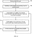
- the method includes receiving at least a first signal.
- a human operator may have knowledge of the type of fuel stored in the fuel tank 20 and the human operator may operate the user input device 16 to select or define the type of fuel.
- the controller 14 may receive a signal from the user input device 16 that includes user input data defining the fuel 40.
- the user input data in the signal may identify the name of the fuel 40 (for example, gasoline, fuel oil, diesel fuel, and so on), or may identify the classification of the fuel 40 (for example, aromatic, paraffinic, naphthenic, and so on), or may identify a combustion property of the fuel 40 (for example, octane number or cetane number).
- the first sensor arrangement 22 may sense one or more properties of the fuel 40.
- the controller 14 may receive a signal from the first sensor arrangement 22 that includes data for the sensed one or more properties of the fuel 40.
- the first sensor arrangement 22 may sense a mass flow rate of the fuel 40, and the controller 14 may receive a signal from the first sensor arrangement 22 that includes mass flow rate data.
- the first sensor arrangement 22 may sense a combustion property of the fuel 40 (octane number or cetane number for example), and the controller 14 may receive a signal from the first sensor arrangement 22 that includes the combustion property of the fuel 40.
- the second sensor arrangement 64 may sense one or more operating parameters of the reciprocating internal combustion engine 12.
- the controller 14 may receive a signal from the second sensor arrangement 64 that includes data for the sensed one or more operating parameters.
- the second sensor arrangement 64 may sense engine knocking and/or engine speed and/or engine power of the reciprocating internal combustion engine 12, and the controller 14 may receive a signal from the second sensor arrangement 64 that includes engine knocking data and/or engine speed data and/or engine power data.
- the controller 14 may receive any combination of signals from the user input device 16, the first sensor arrangement 22, and the second sensor arrangement 64.
- the method includes determining a quantity of liquid air to be injected using at least the received first signal.
- the memory 32 may store a data structure 70 (such as a look-up table) that defines quantities of liquid air to be injected into the cavity 58 of the cylinder 44 per stroke for a plurality of variables (such as fuel type, fuel classification, mass flow rate, combustion property, engine knocking level, engine speed level, engine power level, and so on).
- the controller 14 may use the data in at least the first signal to read the data structure 70 to determine a quantity of liquid air to be injected into the cavity 58 of the cylinder 44 per stroke.
- the controller 14 may use data from the user input device 16 to identify the fuel type (petroleum for example), and may also use data from the first sensor arrangement 22 to identify a combustion property (octane number for example) of the fuel 40 to determine a quantity of liquid air to be injected per engine stroke.
- the fuel type petroleum for example
- a combustion property octane number for example
- the data structure 70 may not be stored in the memory 32 and may instead be stored remotely from the apparatus 12 (in cloud storage for example).
- the method includes controlling injection of the determined quantity of liquid air, into the first end 60 of the cavity 58 at a first time when the piston 46 is closer to the first end 60 than the second end 62.
- the controller 14 may control the liquid air pump arrangement 28 to pump the liquid air 42 from the liquid air tank 26 to the reciprocating internal combustion engine 12, and may control the first valve 52 to move to the open configuration to allow liquid air to be injected into the cavity 58.
- the controller 14 may control the first valve 52 to move to the closed configuration in response to the injection of liquid air into the cavity 58 being completed.
- the piston 46 may be closer to the first end 60 than the second end 62 when the piston head 47 is closer to the first end 60 than the second end 62. In other examples, the piston 46 may be closer to the first end 60 than the second end 62 when a midpoint of the piston 46 (that is, a position halfway between the piston head 47 and the surface opposite the piston head 47) is closer to the first end 60 than the second end 62.
- block 72 may include controlling injection of the determined quantity of liquid air into the first end 60 of the cavity 58 at a first time when the piston 46 is at or near the first position (that is, the highest position of the piston 46 within the cavity 58).
- the determined quantity of liquid air may be injected into the first end 60 of the cavity 58, without fuel being injected, to cause the piston 46 to perform a first power stroke.
- the controller 14 may control the fuel pump arrangement 24 to not pump the fuel 40 from the fuel tank 20 to the reciprocating internal combustion engine 12, or may maintain the fuel pump arrangement 24 in an inactive state. Additionally at the first time, the controller 14 may control the second valve 54 to move to the closed configuration (or to remain in the closed configuration) to prevent the fuel 40 from being injected into the cavity 58.
- Fig. 3 illustrates a schematic diagram of the reciprocating internal combustion engine 12 receiving liquid air 42.
- the first valve 52 is in the open configuration to allow liquid air 42 to enter the cavity 58 between the piston head 47 and the first end 60 of the cavity 58.
- the second valve 54 is in the closed configuration to prevent fuel 40 from entering the cavity 58 between the piston head 47 and the first end 60 of the cavity 58.
- the third valve 56 is in the closed configuration to prevent fluid being exhausted from the cavity 58.
- Fig. 4 illustrates a schematic diagram of the reciprocating internal combustion engine 12 performing a first power stroke.
- the liquid air 42 in the cavity 58 receives thermal energy from the reciprocating internal combustion engine 12, changes phase to a gas, and expands within the cavity 58. Since the first valve 52, the second valve 54 and the third valve 56 are in their closed configurations, the phase change and expansion of the liquid air 42 applies pressure to the piston 46 and causes the piston 46 to move towards the second end 62 of the cavity 58 and perform a first power stroke (as indicated by the arrow with reference numeral 74).
- the piston 46 may move towards the first end 60 of the cavity 58 and perform a compression stroke (that is, the air in the cavity 58 is compressed between the piston head 47 and the cylinder 44).
- the method includes controlling injection of fuel 40 into the first end 60 of the cavity 58 when the piston 46 is closer to the first end 60 than the second end 62.
- the controller 14 may control the fuel pump arrangement 24 to pump the fuel 40 from the fuel tank 20 to the reciprocating internal combustion engine 12, and may control the second valve 54 to move to the open configuration to allow the fuel 40 to be injected into the cavity 58.
- the piston 46 may be closer to the first end 60 than the second end 62 when the piston head 47 is closer to the first end 60 than the second end 62. In other examples, the piston 46 may be closer to the first end 60 than the second end 62 when a midpoint of the piston 46 (that is, a position halfway between the piston head 47 and the surface opposite the piston head 47) is closer to the first end 60 than the second end 62. In some examples, block 76 may include controlling injection of a quantity of fuel into the first end 60 of the cavity 58 when the piston 46 is at or near the first position (that is, at or near the highest position of the piston 46 within the cavity 58).
- block 76 may be performed at a second time that may be subsequent to the first power stroke and the compression stroke, and causes the piston 46 to perform a second power stroke (thus providing the reciprocating internal combustion engine 12 with a thermodynamic cycle having two power strokes).
- block 76 may be performed at the same time as, or immediately after, block 72 to cause the piston 46 to perform a single power stroke per thermodynamic cycle of the reciprocating internal combustion engine 12.
- the thermodynamic cycle may consist of two strokes or four strokes.
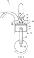
- Fig. 5 illustrates a schematic diagram of ignition within the reciprocating internal combustion engine 12.
- the first valve 52, the second valve 54 and the third valve 56 are in their closed configurations, and the air and fuel mixture in the cavity 58 has been ignited.
- the air and fuel mixture may ignite due to relatively high temperatures caused by high pressure within the cavity 58 (that is, the air and fuel mixture is ignited through compression ignition).
- the reciprocating internal combustion engine 12 may include one or more spark plugs for igniting the air and fuel mixture within the cavity 58 (that is, the air and fuel mixture is ignited through spark ignition).
- Fig. 6 illustrates a schematic diagram of the reciprocating internal combustion engine 12 performing a second power stroke.
- the first valve 52, the second valve 54 and the third valve 56 are in their closed configurations, the combustion of the air and fuel mixture applies pressure to the piston 46 and causes the piston 46 to move towards the second end 62 of the cavity 58 and perform a second power stroke (as indicated by the arrow with reference numeral 78).
- the method may include controlling exhaust from the reciprocating internal combustion engine 12. For example, when the piston 46 is at, or near the second position (that is, at or near the end of a power stroke), the controller 14 may control the third valve 56 to move to the open configuration to allow combustion products from the air and fuel mixture to be exhausted from the cavity 58.
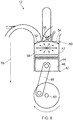
- Fig. 7 illustrates a schematic diagram of the reciprocating internal combustion engine 12 performing an exhaust stroke.
- the piston 46 is at, or near the end of the second power stroke
- the first valve 52 and the second valve 54 are in their closed configurations
- the third valve 56 is in the open configuration to allow combustion products to be exhausted from the cavity 58.
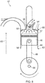
- Fig. 8 illustrates a schematic diagram of the reciprocating internal combustion engine 12 towards the end of the exhaust stroke.
- the piston 46 moves towards the first position in the direction of arrow 82 and causes combustion products to be exhausted via the third valve 56.
- the method may then return to block 72 to perform another first power stroke using the quantity of liquid air determined at block 68.
- the quantity of liquid air to be injected can be determined from a received signal. This may advantageously enable the reciprocating internal combustion engine 12 to use various different fuels since the compression ratio of the engine 12 may be varied to combust a desired fuel by varying the quantity of liquid air to be injected.
- the method may provide the reciprocating internal combustion engine 12 with a thermodynamic cycle having two power strokes. This may result in the reciprocating internal combustion engine 12 being more balanced and therefore less likely to vibrate during operation.
- the liquid air and the fuel may be injected into the cavity 58 at different times and in different strokes. This may advantageously prevent the liquid air from freezing the fuel when injected into the cavity 58.
- the use of liquid air may advantageously result in a lower average temperature of the components in the reciprocating internal combustion engine 12 and may thus reduce wear within, and increase the life of, the reciprocating internal combustion engine 12.
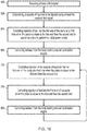
- Fig. 9 illustrates a flow chart of a method of controlling the reciprocating internal combustion engine 12 according to a second example.
- the method illustrated in Fig. 9 is similar to the method illustrated in Fig. 2 , and where the blocks are similar, the same reference numerals are used.
- the method illustrated in Fig. 9 differs from the method illustrated in Fig. 2 in that subsequent to block 80, the method may return to block 66.
- This feedback loop may advantageously enable the controller 14 to optimise the quantity of liquid air to be injected into the reciprocating internal combustion engine 12 during operation.
- the second sensor arrangement 64 may sense one or more operating parameters (engine knocking for example) of the reciprocating internal combustion engine 12 during a power stroke (for example, the first power stroke and/or the second power stroke discussed above), and/or the compression stroke, and/or the exhaust stroke.
- the controller 14 may receive data from the second sensor arrangement 64 for the sensed one or more operating parameters at block 66 and then determine a quantity of liquid air to be injected for the subsequent first power stroke. For example, where the controller 14 determines engine knocking from the signal received from the second sensor arrangement 64, the controller 14 may reduce the quantity of liquid air to be injected at block 72 to reduce engine knocking.
- a human operator may initially operate the user input device 16 to input the fuel type of the fuel 40 in the fuel tank 20.
- the controller 14 may determine an initial quantity of liquid air to be injected into the reciprocating internal combustion engine 12 using the user input signal and the data structure 70.
- the controller 14 may receive data from the first sensor arrangement 22 for the mass flow rate of the fuel 40.
- the controller 14 may use the mass flow rate data to optimise the quantity of liquid air to be injected into the reciprocating internal combustion engine 12.
- Fig. 10 illustrates a flow chart of a method of controlling the reciprocating internal combustion engine 12 according to a third example.
- the method illustrated in Fig. 10 is similar to the methods illustrated in Figs. 2 and 9 and where the features are similar, the same reference numerals are used.
- the method illustrated in Fig. 10 differs from the methods illustrated in Figs. 2 and 9 in that the method illustrated in Fig. 10 further comprises blocks 84 and 86 which may be performed between blocks 68 and 72, or may be performed prior to block 68.
- the method includes controlling injection of the fuel 40 into the first end 60 of the cavity 58 at a third time (which is prior to the first time and the second time) when the piston 46 is closer to the first end 60 than the second end 62 to cause the piston 46 to perform an initial power stroke.
- the controller 14 may control the reciprocating internal combustion engine 12 to perform an intake stroke (where gaseous air is injected into the cavity 58), a compression stroke, and then an initial power stroke to increase the temperature of the reciprocating internal combustion engine 12.
- the method includes controlling exhaust from the reciprocating internal combustion engine 12.
- the controller 14 may control the third valve 56 to move to the open configuration to allow combustion products to be exhausted from the reciprocating internal combustion engine 12.
- the method illustrated in Fig. 10 may be advantageous in that the initial thermodynamic cycle may raise the temperature of the reciprocating internal combustion engine 12 and thus cause improved expansion of injected liquid air within the cavity 58 at block 72. This may improve the performance of the reciprocating internal combustion engine 12 during initial operation.
Landscapes
- Engineering & Computer Science (AREA)
- Mechanical Engineering (AREA)
- General Engineering & Computer Science (AREA)
- Chemical & Material Sciences (AREA)
- Combustion & Propulsion (AREA)
- Electrical Control Of Air Or Fuel Supplied To Internal-Combustion Engine (AREA)
- Combustion Methods Of Internal-Combustion Engines (AREA)
- Combined Controls Of Internal Combustion Engines (AREA)
Abstract
Description
- The present disclosure concerns apparatus and methods for controlling reciprocating internal combustion engines.
- Reciprocating internal combustion engines usually include one or more cylinders which define a cavity, and a piston moveable within the cavity of the cylinder. A hydrocarbon fuel (such as diesel or petroleum) may be injected into the cylinder and ignited. The pressure generated by the combustion of the hydrocarbon fuel causes the piston to move reciprocally within the cylinder and rotate a crankshaft.
- According to a first aspect there is provided a method of controlling a reciprocating internal combustion engine comprising: a cylinder defining a cavity having a first end and a second end; and a piston moveable within the cavity of the cylinder between the first end and the second end, the method comprising: receiving at least a first signal; determining a quantity of liquid air to be injected using at least the received first signal; controlling injection of the determined quantity of liquid air into the first end of the cavity at a first time when the piston is closer to the first end than the second end.
- The first signal may include user input data defining the fuel.
- The first signal may include data defining one or more properties of the fuel. The one or more properties may include a combustion property of the fuel.
- The first signal may include data defining an operating parameter of the reciprocating internal combustion engine.
- The method may further comprise controlling injection of fuel into the first end of the cavity to cause the piston to perform a power stroke.
- The determined quantity of liquid air may be injected into the first end of the cavity without fuel to cause the piston to perform a first power stroke.
- The method may further comprise controlling injection of fuel into the first end of the cavity at a second time when the piston is closer to the first end than the second end to cause the piston to perform a second power stroke.
- The method may further comprise controlling injection of fuel into the first end of the cavity at a third time when the piston is closer to the first end than the second end to cause the piston to perform an initial power stroke, the third time being prior to the first time.
- The liquid air may have greater oxygen content than atmospheric air.
- According to a second aspect there is provided a computer program that, when read by a computer, causes performance of the method as described in the preceding paragraphs.
- According to a third aspect there is provided a non-transitory computer readable storage medium comprising computer readable instructions that, when read by a computer, cause performance of the method as described in the preceding paragraphs.
- According to a fourth aspect there is provided apparatus for controlling a reciprocating internal combustion engine comprising: a cylinder defining a cavity having a first end and a second end; and a piston moveable within the cavity of the cylinder between the first end and the second end, the apparatus comprising a controller configured to: receive at least a first signal; determine a quantity of liquid air to be injected using at least the received first signal; control injection of the determined quantity of liquid air into the first end of the cavity at a first time when the piston is closer to the first end than the second end.
- The first signal may include user input data defining the fuel.
- The first signal may include data defining one or more properties of the fuel. The one or more properties may include a combustion property of the fuel.
- The first signal may include data defining an operating parameter of the reciprocating internal combustion engine.
- The controller may be configured to control injection of fuel into the first end of the cavity to cause the piston to perform a power stroke.
- The determined quantity of liquid air may be injected into the first end of the cavity without fuel to cause the piston to perform a first power stroke.
- The controller may be configured to control injection of fuel into the first end of the cavity at a second time when the piston is closer to the first end than the second end to cause the piston to perform a second power stroke.
- The controller may be configured to control injection of fuel into the first end of the cavity at a third time when the piston is closer to the first end than the second end to cause the piston to perform an initial power stroke, the third time being prior to the first time.
- The liquid air may have greater oxygen content than atmospheric air.
- The skilled person will appreciate that except where mutually exclusive, a feature described in relation to any one of the above aspects may be applied mutatis mutandis to any other aspect. Furthermore except where mutually exclusive any feature described herein may be applied to any aspect and/or combined with any other feature described herein.
- Embodiments will now be described by way of example only, with reference to the Figures, in which:
-
Fig. 1 illustrates a schematic diagram of apparatus for controlling a reciprocating internal combustion engine according to various examples; -
Fig. 2 illustrates a flow chart of a method of controlling the reciprocating internal combustion engine according to a first example; -
Fig. 3 illustrates a schematic diagram of the reciprocating internal combustion engine receiving liquid air; -
Fig. 4 illustrates a schematic diagram of the reciprocating internal combustion engine performing a first power stroke; -
Fig. 5 illustrates a schematic diagram of ignition within the reciprocating internal combustion engine; -
Fig. 6 illustrates a schematic diagram of the reciprocating internal combustion engine performing a second power stroke; -
Fig. 7 illustrates a schematic diagram of the reciprocating internal combustion engine performing an exhaust stroke; -
Fig. 8 illustrates a schematic diagram of the reciprocating internal combustion engine towards the end of the exhaust stroke; -
Fig. 9 illustrates a flow chart of a method of controlling the reciprocating internal combustion engine according to a second example; and -
Fig. 10 illustrates a flow chart of a method of controlling the reciprocating internal combustion engine according to a third example. - In the following description, the terms 'connected' and 'coupled' mean operationally connected and coupled. It should be appreciated that there may be any number of intervening components between the mentioned features, including no intervening components.
-
Fig. 1 illustrates a schematic diagram ofapparatus 10 for controlling a reciprocatinginternal combustion engine 12. Theapparatus 10 includes acontroller 14, auser input device 16, adisplay 18, afuel tank 20, a first sensor arrangement 22, afuel pump arrangement 24, aliquid air tank 26, and a liquidair pump arrangement 28. In some examples, theapparatus 10 may also comprise the reciprocatinginternal combustion engine 12. - In summary, the
apparatus 10 is configured to control injection of liquid air into the reciprocatinginternal combustion engine 12 to cause the reciprocatinginternal combustion engine 12 to perform an additional power stroke. The quantity of liquid air injected into the reciprocatinginternal combustion engine 12 may be varied to provide the reciprocatinginternal combustion engine 12 with a variable compression ratio. - In some examples, the
apparatus 10 may be a module. As used herein, the wording 'module' refers to a device or apparatus where one or more features are included at a later time and, possibly, by another manufacturer or by an end user. For example, where theapparatus 10 is a module, theapparatus 10 may only include thecontroller 14, and the remaining features (such as theuser input device 16, thedisplay 18, thefuel tank 20, the first sensor arrangement 22, thefuel pump arrangement 24, theliquid air tank 26, and the liquid air pump arrangement 28) may be added by another manufacturer, or by an end user. - The
controller 14, theuser input device 16, thedisplay 18, the sensor arrangement 22, thefuel pump arrangement 24, the reciprocatinginternal combustion engine 12, and the liquidair pump arrangement 28 may be coupled to one another via wireless links and may consequently comprise transceiver circuitry and one or more antennas. Additionally or alternatively, thecontroller 14, theuser input device 16, thedisplay 18, the sensor arrangement 22, thefuel pump arrangement 24, the reciprocatinginternal combustion engine 12, and the liquidair pump arrangement 28 may be coupled to one another via wired links and may consequently comprise interface circuitry (such as a Universal Serial Bus (USB) socket) which are connected via cables. It should be appreciated that thecontroller 14, theuser input device 16, thedisplay 18, the sensor arrangement 22, thefuel pump arrangement 24, the reciprocatinginternal combustion engine 12, and the liquidair pump arrangement 28 may be coupled to one another via any combination of wired and wireless links. - The
controller 14 may comprise any suitable circuitry to cause performance of the methods described herein and as illustrated inFigs. 2 ,9 and10 . Thecontroller 14 may comprise: control circuitry; and/or processor circuitry; and/or at least one application specific integrated circuit (ASIC); and/or at least one field programmable gate array (FPGA); and/or single or multi-processor architectures; and/or sequential/parallel architectures; and/or at least one programmable logic controller (PLC); and/or at least one microprocessor; and/or at least one microcontroller; and/or a central processing unit (CPU); and/or a graphics processing unit (GPU), to perform the methods. - The
controller 14 may be positioned remote from the reciprocating internal combustion engine 12 (for example, thecontroller 14 may be positioned outside of a housing of the engine 12), may be a part of the reciprocating internal combustion engine 12 (for example, thecontroller 14 may be positioned within a housing of the engine 12), or may be distributed between the reciprocatinginternal combustion engine 12 and a location remote from the reciprocatinginternal combustion engine 12. - In various examples, the
controller 14 may comprise at least oneprocessor 30 and at least onememory 32. Thememory 32 stores acomputer program 34 comprising computer readable instructions that, when read by theprocessor 30, causes performance of the methods described herein, and as illustrated inFigs. 2 ,9 and10 . Thecomputer program 34 may be software or firmware, or may be a combination of software and firmware. - The
processor 30 may be located on the reciprocatinginternal combustion engine 12, or may be located remote from the reciprocatinginternal combustion engine 12, or may be distributed between the reciprocatinginternal combustion engine 12 and a location remote from the reciprocatinginternal combustion engine 12. Theprocessor 30 may include at least one microprocessor and may comprise a single core processor, may comprise multiple processor cores (such as a dual core processor or a quad core processor), or may comprise a plurality of processors (at least one of which may comprise multiple processor cores). - The
memory 32 may be located on the reciprocatinginternal combustion engine 12, or may be located remote from the reciprocatinginternal combustion engine 12, or may be distributed between the reciprocatinginternal combustion engine 12 and a location remote from the reciprocatinginternal combustion engine 12. Thememory 32 may be any suitable non-transitory computer readable storage medium, data storage device or devices, and may comprise a hard disk drive and/or a solid state drive. Thememory 32 may be permanent non-removable memory, or may be removable memory (such as a universal serial bus (USB) flash drive or a secure digital card). Thememory 32 may include: local memory employed during actual execution of thecomputer program 34; bulk storage; and cache memories which provide temporary storage of at least some computer readable or computer usable program code to reduce the number of times code may be retrieved from bulk storage during execution of the code. - The
computer program 34 may be stored on a non-transitory computerreadable storage medium 36. Thecomputer program 34 may be transferred from the non-transitory computerreadable storage medium 36 to thememory 32. The non-transitory computerreadable storage medium 36 may be, for example, a USB flash drive, a secure digital (SD) card, or an optical disc. In some examples, thecomputer program 34 may be transferred to thememory 32 via a signal 38 (such as a wireless signal or a wired signal). - Input/output devices may be coupled to the
controller 14 either directly or through intervening input/output controllers. Various communication adaptors may also be coupled to thecontroller 14 to enable theapparatus 10 to become coupled to other apparatus or remote printers or storage devices through intervening private or public networks. Non-limiting examples include modems and network adaptors of such communication adaptors. - The
user input device 16 may comprise any suitable device or devices for enabling a human operator to provide an input to theapparatus 10. For example, theuser input device 16 may comprise one or more of a keyboard, a keypad, a touchpad, a touchscreen display, and a computer mouse. Thecontroller 14 is configured to receive signals from theuser input device 16. - The
display 18 may be any suitable device for displaying information to the human operator. For example, thedisplay 18 may be a liquid crystal display, a light emitting diode display, an active matrix organic light emitting diode display, a thin film transistor display, or a cathode ray tube display. Thecontroller 14 is arranged to control thedisplay 18 to display information to the human operator. - The
fuel tank 20 may comprise any suitable container, or containers, for storing one or more fuels 40. For example, thefuel tank 20 may comprise a single container storing diesel. In another example, thefuel tank 20 may comprise a first container storing diesel, a second container storing petroleum, and a third container storing liquefied natural gas. - The first sensor arrangement 22 may comprise any suitable sensor, or sensors, that are configured to sense one or more properties of the
fuel 40. For example, the first sensor arrangement 22 may comprise one or more flow meters that are configured to sense the mass flow rate of thefuel 40 within thefuel tank 20. By way of another example, the first sensor arrangement 22 may comprise one or more sensors for determining a combustion property (such as octane number or cetane number) of thefuel 40. Thecontroller 14 is configured to receive signals from the first sensor arrangement 22. - The
fuel pump arrangement 24 comprises one or more pumps that are configured to move thefuel 40 from thefuel tank 20 to the reciprocatinginternal combustion engine 12. For example, where thefuel tank 20 comprises a plurality of containers storing different fuels, thefuel pump arrangement 24 may comprise a pump in each fuel line between each container and the reciprocatinginternal combustion engine 12. Thecontroller 14 is configured to control the operation of thefuel pump arrangement 24. - The
liquid air tank 26 may comprise any suitable container, or containers, for storingliquid air 42. For example, theliquid air tank 26 may comprise one or more vacuum insulated containers. In other examples, theliquid air tank 26 may comprise one or more containers that use multi-layered insulation and aerogels. Such containers may or may not include a vacuum layer. Theliquid air 42 may have the same composition as atmospheric air (that is, a composition of approximately 78% nitrogen, 21% oxygen, and 1% argon), or may have a different composition to atmospheric air. For example, theliquid air 42 may have an oxygen rich composition (that is, a composition having greater oxygen content than atmospheric air) or may be liquid oxygen. - The liquid
air pump arrangement 28 comprises one or more pumps for moving theliquid air 42 stored in theliquid air tank 26 to the reciprocatinginternal combustion engine 12. Thecontroller 14 is configured to control the operation of the liquidair pump arrangement 28. - The reciprocating
internal combustion engine 12 comprises acylinder 44, apiston 46, a connectingrod 48, acrankshaft 50, afirst valve 52, asecond valve 54, and athird valve 56. It should be appreciated that the reciprocatinginternal combustion engine 12 may comprise a plurality ofcylinders 44,pistons 46, connectingrods 48,crankshafts 50,first valves 52,second valves 54, and third valves, and that a single arrangement is illustrated to maintain the clarity ofFig. 1 . - The
cylinder 44 defines acavity 58 having afirst end 60 and asecond end 62. Thecylinder 44 may comprise any suitable material and may comprise a material having a low coefficient of thermal expansion (for example, a ceramic material). Thepiston 46 includes apiston head 47 and is arranged to move reciprocally within thecavity 58 of thecylinder 44 between a first position in proximity to thefirst end 60 and a second position in proximity to thesecond end 62 of thecavity 58. Thecrankshaft 50 is connected to thepiston 46 via the connectingrod 48 and is arranged to convert the reciprocating motion of thepiston 48 into rotational motion. - The
first valve 52 is positioned at thefirst end 60 of thecavity 58 and is arranged to receive theliquid air 42 from the liquidair pump arrangement 28. Thefirst valve 52 has an open configuration in whichliquid air 42 is injected into thecavity 58, and a closed configuration which preventsliquid air 42 from being injected into thecavity 58. Thecontroller 14 is configured to control the operation of thefirst valve 52. - The
second valve 54 is positioned at thefirst end 60 of thecavity 58 and is arranged to receivefuel 40 from thefuel pump arrangement 24. Thesecond valve 54 has an open configuration in which fuel 40 is injected into thecavity 58, and a closed configuration which preventsfuel 40 from being injected into thecavity 58. Thecontroller 14 is configured to control the operation of thesecond valve 54. - The
third valve 56 is positioned at thefirst end 60 of thecavity 58 and is arranged to exhaust gas from thecavity 58. Thethird valve 56 has an open configuration in which gases are exhausted from thecavity 58, and a closed configuration which prevents gases from being exhausted from thecavity 58. Thecontroller 14 is configured to control the operation of thethird valve 56. - The
apparatus 10 may also comprise asecond sensor arrangement 64 that is configured to sense one or more operating parameters of the reciprocatinginternal combustion engine 12. For example, thesecond sensor arrangement 64 may comprise one or more microphones for sensing engine knocking. In another example, thesecond sensor arrangement 64 may comprise one or more sensors for sensing the operating speed and/or power of the reciprocating internal combustion engine 12 (for example, by sensing the rotational speed of the crankshaft 50). Thesecond sensor arrangement 64 may be part of the reciprocatinginternal combustion engine 12, or may be remote from the reciprocatinginternal combustion engine 12. Thecontroller 14 is configured to receive signals from thesecond sensor arrangement 64. - The operation of the
apparatus 10 according to a first example is described in the following paragraphs with reference toFigs. 2 to 8 . - At
block 66, the method includes receiving at least a first signal. - In a first example, a human operator may have knowledge of the type of fuel stored in the
fuel tank 20 and the human operator may operate theuser input device 16 to select or define the type of fuel. Thecontroller 14 may receive a signal from theuser input device 16 that includes user input data defining thefuel 40. The user input data in the signal may identify the name of the fuel 40 (for example, gasoline, fuel oil, diesel fuel, and so on), or may identify the classification of the fuel 40 (for example, aromatic, paraffinic, naphthenic, and so on), or may identify a combustion property of the fuel 40 (for example, octane number or cetane number). - In a second example, the first sensor arrangement 22 may sense one or more properties of the
fuel 40. Thecontroller 14 may receive a signal from the first sensor arrangement 22 that includes data for the sensed one or more properties of thefuel 40. For example, the first sensor arrangement 22 may sense a mass flow rate of thefuel 40, and thecontroller 14 may receive a signal from the first sensor arrangement 22 that includes mass flow rate data. In another example, the first sensor arrangement 22 may sense a combustion property of the fuel 40 (octane number or cetane number for example), and thecontroller 14 may receive a signal from the first sensor arrangement 22 that includes the combustion property of thefuel 40. - In a third example, the
second sensor arrangement 64 may sense one or more operating parameters of the reciprocatinginternal combustion engine 12. Thecontroller 14 may receive a signal from thesecond sensor arrangement 64 that includes data for the sensed one or more operating parameters. For example, thesecond sensor arrangement 64 may sense engine knocking and/or engine speed and/or engine power of the reciprocatinginternal combustion engine 12, and thecontroller 14 may receive a signal from thesecond sensor arrangement 64 that includes engine knocking data and/or engine speed data and/or engine power data. - It should be appreciated that at
block 66, thecontroller 14 may receive any combination of signals from theuser input device 16, the first sensor arrangement 22, and thesecond sensor arrangement 64. - At
block 68, the method includes determining a quantity of liquid air to be injected using at least the received first signal. For example, thememory 32 may store a data structure 70 (such as a look-up table) that defines quantities of liquid air to be injected into thecavity 58 of thecylinder 44 per stroke for a plurality of variables (such as fuel type, fuel classification, mass flow rate, combustion property, engine knocking level, engine speed level, engine power level, and so on). Thecontroller 14 may use the data in at least the first signal to read thedata structure 70 to determine a quantity of liquid air to be injected into thecavity 58 of thecylinder 44 per stroke. For example, thecontroller 14 may use data from theuser input device 16 to identify the fuel type (petroleum for example), and may also use data from the first sensor arrangement 22 to identify a combustion property (octane number for example) of thefuel 40 to determine a quantity of liquid air to be injected per engine stroke. - It should be appreciated that in some examples, the
data structure 70 may not be stored in thememory 32 and may instead be stored remotely from the apparatus 12 (in cloud storage for example). - At
block 72, the method includes controlling injection of the determined quantity of liquid air, into thefirst end 60 of thecavity 58 at a first time when thepiston 46 is closer to thefirst end 60 than thesecond end 62. - For example, the
controller 14 may control the liquidair pump arrangement 28 to pump theliquid air 42 from theliquid air tank 26 to the reciprocatinginternal combustion engine 12, and may control thefirst valve 52 to move to the open configuration to allow liquid air to be injected into thecavity 58. Thecontroller 14 may control thefirst valve 52 to move to the closed configuration in response to the injection of liquid air into thecavity 58 being completed. - The
piston 46 may be closer to thefirst end 60 than thesecond end 62 when thepiston head 47 is closer to thefirst end 60 than thesecond end 62. In other examples, thepiston 46 may be closer to thefirst end 60 than thesecond end 62 when a midpoint of the piston 46 (that is, a position halfway between thepiston head 47 and the surface opposite the piston head 47) is closer to thefirst end 60 than thesecond end 62. In some examples, block 72 may include controlling injection of the determined quantity of liquid air into thefirst end 60 of thecavity 58 at a first time when thepiston 46 is at or near the first position (that is, the highest position of thepiston 46 within the cavity 58). - In some examples, the determined quantity of liquid air may be injected into the
first end 60 of thecavity 58, without fuel being injected, to cause thepiston 46 to perform a first power stroke. In these examples, at the first time thecontroller 14 may control thefuel pump arrangement 24 to not pump thefuel 40 from thefuel tank 20 to the reciprocatinginternal combustion engine 12, or may maintain thefuel pump arrangement 24 in an inactive state. Additionally at the first time, thecontroller 14 may control thesecond valve 54 to move to the closed configuration (or to remain in the closed configuration) to prevent thefuel 40 from being injected into thecavity 58. -
Fig. 3 illustrates a schematic diagram of the reciprocatinginternal combustion engine 12 receivingliquid air 42. In more detail, thefirst valve 52 is in the open configuration to allowliquid air 42 to enter thecavity 58 between thepiston head 47 and thefirst end 60 of thecavity 58. Thesecond valve 54 is in the closed configuration to preventfuel 40 from entering thecavity 58 between thepiston head 47 and thefirst end 60 of thecavity 58. Thethird valve 56 is in the closed configuration to prevent fluid being exhausted from thecavity 58. -
Fig. 4 illustrates a schematic diagram of the reciprocatinginternal combustion engine 12 performing a first power stroke. Theliquid air 42 in thecavity 58 receives thermal energy from the reciprocatinginternal combustion engine 12, changes phase to a gas, and expands within thecavity 58. Since thefirst valve 52, thesecond valve 54 and thethird valve 56 are in their closed configurations, the phase change and expansion of theliquid air 42 applies pressure to thepiston 46 and causes thepiston 46 to move towards thesecond end 62 of thecavity 58 and perform a first power stroke (as indicated by the arrow with reference numeral 74). - Subsequent to the first power stroke, the
piston 46 may move towards thefirst end 60 of thecavity 58 and perform a compression stroke (that is, the air in thecavity 58 is compressed between thepiston head 47 and the cylinder 44). - At
block 76, the method includes controlling injection offuel 40 into thefirst end 60 of thecavity 58 when thepiston 46 is closer to thefirst end 60 than thesecond end 62. For example, thecontroller 14 may control thefuel pump arrangement 24 to pump thefuel 40 from thefuel tank 20 to the reciprocatinginternal combustion engine 12, and may control thesecond valve 54 to move to the open configuration to allow thefuel 40 to be injected into thecavity 58. - As mentioned in the preceding paragraphs, the
piston 46 may be closer to thefirst end 60 than thesecond end 62 when thepiston head 47 is closer to thefirst end 60 than thesecond end 62. In other examples, thepiston 46 may be closer to thefirst end 60 than thesecond end 62 when a midpoint of the piston 46 (that is, a position halfway between thepiston head 47 and the surface opposite the piston head 47) is closer to thefirst end 60 than thesecond end 62. In some examples, block 76 may include controlling injection of a quantity of fuel into thefirst end 60 of thecavity 58 when thepiston 46 is at or near the first position (that is, at or near the highest position of thepiston 46 within the cavity 58). - Where the determined quantity of liquid air is injected into the
cavity 58 without fuel, block 76 may be performed at a second time that may be subsequent to the first power stroke and the compression stroke, and causes thepiston 46 to perform a second power stroke (thus providing the reciprocatinginternal combustion engine 12 with a thermodynamic cycle having two power strokes). In other examples, block 76 may be performed at the same time as, or immediately after, block 72 to cause thepiston 46 to perform a single power stroke per thermodynamic cycle of the reciprocatinginternal combustion engine 12. In these examples, the thermodynamic cycle may consist of two strokes or four strokes. -
Fig. 5 illustrates a schematic diagram of ignition within the reciprocatinginternal combustion engine 12. Thefirst valve 52, thesecond valve 54 and thethird valve 56 are in their closed configurations, and the air and fuel mixture in thecavity 58 has been ignited. In some examples, the air and fuel mixture may ignite due to relatively high temperatures caused by high pressure within the cavity 58 (that is, the air and fuel mixture is ignited through compression ignition). In other examples, the reciprocatinginternal combustion engine 12 may include one or more spark plugs for igniting the air and fuel mixture within the cavity 58 (that is, the air and fuel mixture is ignited through spark ignition). -
Fig. 6 illustrates a schematic diagram of the reciprocatinginternal combustion engine 12 performing a second power stroke. Thefirst valve 52, thesecond valve 54 and thethird valve 56 are in their closed configurations, the combustion of the air and fuel mixture applies pressure to thepiston 46 and causes thepiston 46 to move towards thesecond end 62 of thecavity 58 and perform a second power stroke (as indicated by the arrow with reference numeral 78). - At
block 80, the method may include controlling exhaust from the reciprocatinginternal combustion engine 12. For example, when thepiston 46 is at, or near the second position (that is, at or near the end of a power stroke), thecontroller 14 may control thethird valve 56 to move to the open configuration to allow combustion products from the air and fuel mixture to be exhausted from thecavity 58. -
Fig. 7 illustrates a schematic diagram of the reciprocatinginternal combustion engine 12 performing an exhaust stroke. In more detail, thepiston 46 is at, or near the end of the second power stroke, thefirst valve 52 and thesecond valve 54 are in their closed configurations, and thethird valve 56 is in the open configuration to allow combustion products to be exhausted from thecavity 58. -
Fig. 8 illustrates a schematic diagram of the reciprocatinginternal combustion engine 12 towards the end of the exhaust stroke. During the exhaust stroke, thepiston 46 moves towards the first position in the direction ofarrow 82 and causes combustion products to be exhausted via thethird valve 56. - The method may then return to block 72 to perform another first power stroke using the quantity of liquid air determined at
block 68. - The
apparatus 10 and the method illustrated inFig. 2 may provide several advantages. First, the quantity of liquid air to be injected can be determined from a received signal. This may advantageously enable the reciprocatinginternal combustion engine 12 to use various different fuels since the compression ratio of theengine 12 may be varied to combust a desired fuel by varying the quantity of liquid air to be injected. Second, the method may provide the reciprocatinginternal combustion engine 12 with a thermodynamic cycle having two power strokes. This may result in the reciprocatinginternal combustion engine 12 being more balanced and therefore less likely to vibrate during operation. Third, the liquid air and the fuel may be injected into thecavity 58 at different times and in different strokes. This may advantageously prevent the liquid air from freezing the fuel when injected into thecavity 58. Fourth, the use of liquid air may advantageously result in a lower average temperature of the components in the reciprocatinginternal combustion engine 12 and may thus reduce wear within, and increase the life of, the reciprocatinginternal combustion engine 12. -
Fig. 9 illustrates a flow chart of a method of controlling the reciprocatinginternal combustion engine 12 according to a second example. The method illustrated inFig. 9 is similar to the method illustrated inFig. 2 , and where the blocks are similar, the same reference numerals are used. The method illustrated inFig. 9 differs from the method illustrated inFig. 2 in that subsequent to block 80, the method may return to block 66. This feedback loop may advantageously enable thecontroller 14 to optimise the quantity of liquid air to be injected into the reciprocatinginternal combustion engine 12 during operation. - In one example, the
second sensor arrangement 64 may sense one or more operating parameters (engine knocking for example) of the reciprocatinginternal combustion engine 12 during a power stroke (for example, the first power stroke and/or the second power stroke discussed above), and/or the compression stroke, and/or the exhaust stroke. Thecontroller 14 may receive data from thesecond sensor arrangement 64 for the sensed one or more operating parameters atblock 66 and then determine a quantity of liquid air to be injected for the subsequent first power stroke. For example, where thecontroller 14 determines engine knocking from the signal received from thesecond sensor arrangement 64, thecontroller 14 may reduce the quantity of liquid air to be injected atblock 72 to reduce engine knocking. - In another example, a human operator may initially operate the
user input device 16 to input the fuel type of thefuel 40 in thefuel tank 20. Thecontroller 14 may determine an initial quantity of liquid air to be injected into the reciprocatinginternal combustion engine 12 using the user input signal and thedata structure 70. In a subsequent cycle, thecontroller 14 may receive data from the first sensor arrangement 22 for the mass flow rate of thefuel 40. Thecontroller 14 may use the mass flow rate data to optimise the quantity of liquid air to be injected into the reciprocatinginternal combustion engine 12. -
Fig. 10 illustrates a flow chart of a method of controlling the reciprocatinginternal combustion engine 12 according to a third example. The method illustrated inFig. 10 is similar to the methods illustrated inFigs. 2 and9 and where the features are similar, the same reference numerals are used. - The method illustrated in
Fig. 10 differs from the methods illustrated inFigs. 2 and9 in that the method illustrated inFig. 10 further comprisesblocks blocks - At
block 84, the method includes controlling injection of thefuel 40 into thefirst end 60 of thecavity 58 at a third time (which is prior to the first time and the second time) when thepiston 46 is closer to thefirst end 60 than thesecond end 62 to cause thepiston 46 to perform an initial power stroke. For example, thecontroller 14 may control the reciprocatinginternal combustion engine 12 to perform an intake stroke (where gaseous air is injected into the cavity 58), a compression stroke, and then an initial power stroke to increase the temperature of the reciprocatinginternal combustion engine 12. - At
block 86, the method includes controlling exhaust from the reciprocatinginternal combustion engine 12. For example, thecontroller 14 may control thethird valve 56 to move to the open configuration to allow combustion products to be exhausted from the reciprocatinginternal combustion engine 12. - The method illustrated in
Fig. 10 may be advantageous in that the initial thermodynamic cycle may raise the temperature of the reciprocatinginternal combustion engine 12 and thus cause improved expansion of injected liquid air within thecavity 58 atblock 72. This may improve the performance of the reciprocatinginternal combustion engine 12 during initial operation. - It will be understood that the invention is not limited to the embodiments above-described and various modifications and improvements can be made without departing from the concepts described herein. For example, the different embodiments may take the form of an entirely hardware embodiment, an entirely software embodiment, or an embodiment containing both hardware and software elements.
- Except where mutually exclusive, any of the features may be employed separately or in combination with any other features and the disclosure extends to and includes all combinations and sub-combinations of one or more features described herein.
Claims (13)
- A method of controlling a reciprocating internal combustion engine comprising: a cylinder defining a cavity having a first end and a second end; and a piston moveable within the cavity of the cylinder between the first end and the second end, the method comprising:receiving at least a first signal;determining a quantity of liquid air to be injected using at least the received first signal;controlling injection of the determined quantity of liquid air into the first end of the cavity at a first time when the piston is closer to the first end than the second end.
- A method as claimed in claim 1, wherein the first signal includes user input data defining the fuel.
- A method as claimed in claim 1, wherein the first signal includes data defining one or more properties of the fuel.
- A method as claimed in claim 3, wherein the one or more properties include a combustion property of the fuel.
- A method as claimed in claim 1, wherein the first signal includes data defining an operating parameter of the reciprocating internal combustion engine.
- A method as claimed in any of the preceding claims, further comprising controlling injection of fuel into the first end of the cavity to cause the piston to perform a power stroke.
- A method as claimed in any of the preceding claims, wherein the determined quantity of liquid air is injected into the first end of the cavity without fuel to cause the piston to perform a first power stroke.
- A method as claimed in claim 7, further comprising controlling injection of fuel into the first end of the cavity at a second time when the piston is closer to the first end than the second end to cause the piston to perform a second power stroke.
- A method as claimed in any of the preceding claims, further comprising controlling injection of fuel into the first end of the cavity at a third time when the piston is closer to the first end than the second end to cause the piston to perform an initial power stroke, the third time being prior to the first time.
- A method as claimed in any of the preceding claims, wherein the liquid air has greater oxygen content than atmospheric air.
- A computer program that, when read by a computer, causes performance of the method as claimed in any of the preceding claims.
- A non-transitory computer readable storage medium comprising computer readable instructions that, when read by a computer, cause performance of the method as claimed in any of claims 1 to 10.
- Apparatus for controlling a reciprocating internal combustion engine comprising: a cylinder defining a cavity having a first end and a second end; and a piston moveable within the cavity of the cylinder between the first end and the second end, the apparatus comprising a controller configured to perform the method as claimed in any of claims 1 to 10.
Applications Claiming Priority (1)
| Application Number | Priority Date | Filing Date | Title |
|---|---|---|---|
| GBGB1717438.4A GB201717438D0 (en) | 2017-10-24 | 2017-10-24 | Apparatus amd methods for controlling reciprocating internal combustion engines |
Publications (2)
| Publication Number | Publication Date |
|---|---|
| EP3477088A1 true EP3477088A1 (en) | 2019-05-01 |
| EP3477088B1 EP3477088B1 (en) | 2022-08-10 |
Family
ID=60481761
Family Applications (1)
| Application Number | Title | Priority Date | Filing Date |
|---|---|---|---|
| EP18196287.9A Active EP3477088B1 (en) | 2017-10-24 | 2018-09-24 | Apparatus and methods for controlling reciprocating internal combustion engines |
Country Status (4)
| Country | Link |
|---|---|
| US (1) | US10683754B2 (en) |
| EP (1) | EP3477088B1 (en) |
| CN (1) | CN109854361B (en) |
| GB (1) | GB201717438D0 (en) |
Citations (6)
| Publication number | Priority date | Publication date | Assignee | Title |
|---|---|---|---|---|
| JPS59115428A (en) * | 1982-12-23 | 1984-07-03 | Mitsubishi Heavy Ind Ltd | Two-cycle internal-combustion engine |
| JPH01138360A (en) * | 1987-11-26 | 1989-05-31 | Hino Motors Ltd | Engine equipped with exhaust turbosupercharger |
| DE19606559A1 (en) * | 1996-02-22 | 1997-08-28 | Christian Kurpiers | Reciprocating piston engine operating method |
| US20090056670A1 (en) * | 2007-10-10 | 2009-03-05 | Yuanping Zhao | High efficiency integrated heat engine-2 (heihe-2) |
| US20160245235A1 (en) * | 2015-02-21 | 2016-08-25 | Philip Owen Jung | High Thermal Efficiency Six Stroke Internal Combustion Engine with Heat Recovery |
| CN206205989U (en) * | 2016-09-22 | 2017-05-31 | 唐松立 | Pure oxygen alcohols internal combustion dual intensity engine system |
Family Cites Families (16)
| Publication number | Priority date | Publication date | Assignee | Title |
|---|---|---|---|---|
| GB189316900A (en) | 1893-09-08 | 1894-07-14 | Francis William Crossley | Improvements in Internal Combustion Engines. |
| GB190013488A (en) | 1900-07-26 | 1901-07-26 | Frank Bryan | Improvements in or relating to Fluid Pressure Motive Power Engines |
| US3315650A (en) * | 1965-09-17 | 1967-04-25 | Ford Motor Co | Internal combustion engine combustion process |
| US5255519A (en) | 1992-08-14 | 1993-10-26 | Millennium Technologies, Inc. | Method and apparatus for increasing efficiency and productivity in a power generation cycle |
| JP2000220482A (en) * | 1999-01-28 | 2000-08-08 | Osaka Gas Co Ltd | Premixed compression auto-ignition engine and its control method |
| US6311651B1 (en) | 1999-12-17 | 2001-11-06 | Satnarine Singh | Computer controlled six stroke internal combustion engine and its method of operation |
| SE529569C2 (en) * | 2006-01-31 | 2007-09-18 | Cargine Engineering Ab | Two stroke internal combustion engine with liquid injection |
| JP2008267267A (en) * | 2007-04-20 | 2008-11-06 | Nissan Motor Co Ltd | Internal combustion engine |
| GB0803247D0 (en) | 2008-02-22 | 2008-04-02 | Matthews David | Air six shooter |
| US20130340717A1 (en) * | 2012-06-22 | 2013-12-26 | Michael Avery | Methods and systems for conversion of single-fuel engine to multiple-fuel engine with diesel oxidation catalyst |
| WO2014144036A1 (en) * | 2013-03-15 | 2014-09-18 | Angel Enterprise Systems, Inc. | Engine analysis and diagnostic system |
| JPWO2015005097A1 (en) | 2013-07-09 | 2017-03-02 | ヤマハ発動機株式会社 | 6-cycle engine and operation method of 6-cycle engine |
| GB2537246B (en) * | 2013-10-10 | 2020-08-26 | Cummins Inc | Fuel control for dual fuel engines |
| DE102014105237B3 (en) * | 2014-04-11 | 2015-04-09 | Mitsubishi Hitachi Power Systems Europe Gmbh | Method and device for storing and recovering energy |
| GB2537175B (en) | 2015-04-10 | 2019-09-18 | Dearman Engine Company Ltd | Improved Cryogenic Engine System |
| DE102016110112B9 (en) * | 2015-06-11 | 2021-04-01 | Denso Corporation | Fuel injector |
-
2017
- 2017-10-24 GB GBGB1717438.4A patent/GB201717438D0/en not_active Ceased
-
2018
- 2018-09-24 EP EP18196287.9A patent/EP3477088B1/en active Active
- 2018-09-24 US US16/139,265 patent/US10683754B2/en active Active
- 2018-10-24 CN CN201811241322.XA patent/CN109854361B/en active Active
Patent Citations (6)
| Publication number | Priority date | Publication date | Assignee | Title |
|---|---|---|---|---|
| JPS59115428A (en) * | 1982-12-23 | 1984-07-03 | Mitsubishi Heavy Ind Ltd | Two-cycle internal-combustion engine |
| JPH01138360A (en) * | 1987-11-26 | 1989-05-31 | Hino Motors Ltd | Engine equipped with exhaust turbosupercharger |
| DE19606559A1 (en) * | 1996-02-22 | 1997-08-28 | Christian Kurpiers | Reciprocating piston engine operating method |
| US20090056670A1 (en) * | 2007-10-10 | 2009-03-05 | Yuanping Zhao | High efficiency integrated heat engine-2 (heihe-2) |
| US20160245235A1 (en) * | 2015-02-21 | 2016-08-25 | Philip Owen Jung | High Thermal Efficiency Six Stroke Internal Combustion Engine with Heat Recovery |
| CN206205989U (en) * | 2016-09-22 | 2017-05-31 | 唐松立 | Pure oxygen alcohols internal combustion dual intensity engine system |
Also Published As
| Publication number | Publication date |
|---|---|
| GB201717438D0 (en) | 2017-12-06 |
| EP3477088B1 (en) | 2022-08-10 |
| CN109854361B (en) | 2022-06-17 |
| CN109854361A (en) | 2019-06-07 |
| US20190120053A1 (en) | 2019-04-25 |
| US10683754B2 (en) | 2020-06-16 |
Similar Documents
| Publication | Publication Date | Title |
|---|---|---|
| JP7488930B2 (en) | CONTROL DEVICE FOR OPERATING AN INTERNAL COMBUSTION ENGINE, COMPUTER CONTROLLED INTERNAL COMBUSTION ENGINE SYSTEM, AND METHOD OF OPERATING AN INTERNAL COMBUSTION ENGINE - Patent application | |
| CN105697160A (en) | System and method for increasing gaseous fuel displacement | |
| CN107810318A (en) | For the system and method via external sensor detecting and alarm component condition | |
| BR102016000758A2 (en) | systems and methods | |
| US20120016567A1 (en) | Method of controlling the combustion phase of a fuel mixture of a spark-ingnition supercharged internal-combustion engine, notably of gasoline type | |
| Zhao et al. | An experimental study of the cycle stability of hydraulic free-piston engines | |
| AU2016201059A1 (en) | Systems and methods to distinguish engine knock from piston slap | |
| US10557440B2 (en) | Internal combustion engine | |
| US10683754B2 (en) | Apparatus and methods for controlling reciprocating internal combustion engines | |
| US10718211B2 (en) | Apparatus and methods for controlling reciprocating internal combustion engines | |
| KR102310815B1 (en) | Ship Engine and Method for Ship Engine | |
| CN103216341B (en) | An internal combustion engine with a combined fuel oil and fuel gas operation mode | |
| JP6375764B2 (en) | Ignition control device | |
| Field et al. | Internal combustion engines | |
| US20150285135A1 (en) | Combustion engine including an air injector, and power generating system including the combustion engine | |
| US10060261B2 (en) | Rotary synchronized combustion engine | |
| US12448928B2 (en) | Control system for internal combustion engine, internal combustion engine system, and method of controlling internal combustion engine | |
| KR20160025648A (en) | Link structure for applying atkinson cycle in internal combustion engine | |
| JP2024154190A (en) | Internal combustion engine and method for controlling internal combustion engine | |
| JP2015227639A (en) | Engine fuel injection timing control unit | |
| KR20250121129A (en) | Engine control method, engine, vehicle, and computer-readable storage medium | |
| US20070089702A1 (en) | Three cycle internal combustion engine | |
| RO134578A2 (en) | External combustion engine | |
| Tillock et al. | Inherent Advantages and Fuel Efficiency Gains by Eliminating the Crankshaft: 1-D Simulation of a Novel Engine Design | |
| JP2017141687A (en) | Control device of internal combustion engine and control method of internal combustion engine |
Legal Events
| Date | Code | Title | Description |
|---|---|---|---|
| PUAI | Public reference made under article 153(3) epc to a published international application that has entered the european phase |
Free format text: ORIGINAL CODE: 0009012 |
|
| STAA | Information on the status of an ep patent application or granted ep patent |
Free format text: STATUS: THE APPLICATION HAS BEEN PUBLISHED |
|
| AK | Designated contracting states |
Kind code of ref document: A1 Designated state(s): AL AT BE BG CH CY CZ DE DK EE ES FI FR GB GR HR HU IE IS IT LI LT LU LV MC MK MT NL NO PL PT RO RS SE SI SK SM TR |
|
| AX | Request for extension of the european patent |
Extension state: BA ME |
|
| STAA | Information on the status of an ep patent application or granted ep patent |
Free format text: STATUS: REQUEST FOR EXAMINATION WAS MADE |
|
| 17P | Request for examination filed |
Effective date: 20191024 |
|
| RBV | Designated contracting states (corrected) |
Designated state(s): AL AT BE BG CH CY CZ DE DK EE ES FI FR GB GR HR HU IE IS IT LI LT LU LV MC MK MT NL NO PL PT RO RS SE SI SK SM TR |
|
| RAP1 | Party data changed (applicant data changed or rights of an application transferred) |
Owner name: ROLLS-ROYCE PLC |
|
| STAA | Information on the status of an ep patent application or granted ep patent |
Free format text: STATUS: EXAMINATION IS IN PROGRESS |
|
| 17Q | First examination report despatched |
Effective date: 20200326 |
|
| GRAP | Despatch of communication of intention to grant a patent |
Free format text: ORIGINAL CODE: EPIDOSNIGR1 |
|
| STAA | Information on the status of an ep patent application or granted ep patent |
Free format text: STATUS: GRANT OF PATENT IS INTENDED |
|
| GRAS | Grant fee paid |
Free format text: ORIGINAL CODE: EPIDOSNIGR3 |
|
| INTG | Intention to grant announced |
Effective date: 20220608 |
|
| GRAA | (expected) grant |
Free format text: ORIGINAL CODE: 0009210 |
|
| STAA | Information on the status of an ep patent application or granted ep patent |
Free format text: STATUS: THE PATENT HAS BEEN GRANTED |
|
| AK | Designated contracting states |
Kind code of ref document: B1 Designated state(s): AL AT BE BG CH CY CZ DE DK EE ES FI FR GB GR HR HU IE IS IT LI LT LU LV MC MK MT NL NO PL PT RO RS SE SI SK SM TR |
|
| REG | Reference to a national code |
Ref country code: AT Ref legal event code: REF Ref document number: 1510717 Country of ref document: AT Kind code of ref document: T Effective date: 20220815 Ref country code: CH Ref legal event code: EP |
|
| REG | Reference to a national code |
Ref country code: IE Ref legal event code: FG4D |
|
| REG | Reference to a national code |
Ref country code: DE Ref legal event code: R096 Ref document number: 602018039008 Country of ref document: DE |
|
| REG | Reference to a national code |
Ref country code: NL Ref legal event code: MP Effective date: 20220810 |
|
| REG | Reference to a national code |
Ref country code: LT Ref legal event code: MG9D |
|
| PG25 | Lapsed in a contracting state [announced via postgrant information from national office to epo] |
Ref country code: SE Free format text: LAPSE BECAUSE OF FAILURE TO SUBMIT A TRANSLATION OF THE DESCRIPTION OR TO PAY THE FEE WITHIN THE PRESCRIBED TIME-LIMIT Effective date: 20220810 Ref country code: RS Free format text: LAPSE BECAUSE OF FAILURE TO SUBMIT A TRANSLATION OF THE DESCRIPTION OR TO PAY THE FEE WITHIN THE PRESCRIBED TIME-LIMIT Effective date: 20220810 Ref country code: PT Free format text: LAPSE BECAUSE OF FAILURE TO SUBMIT A TRANSLATION OF THE DESCRIPTION OR TO PAY THE FEE WITHIN THE PRESCRIBED TIME-LIMIT Effective date: 20221212 Ref country code: NO Free format text: LAPSE BECAUSE OF FAILURE TO SUBMIT A TRANSLATION OF THE DESCRIPTION OR TO PAY THE FEE WITHIN THE PRESCRIBED TIME-LIMIT Effective date: 20221110 Ref country code: NL Free format text: LAPSE BECAUSE OF FAILURE TO SUBMIT A TRANSLATION OF THE DESCRIPTION OR TO PAY THE FEE WITHIN THE PRESCRIBED TIME-LIMIT Effective date: 20220810 Ref country code: LV Free format text: LAPSE BECAUSE OF FAILURE TO SUBMIT A TRANSLATION OF THE DESCRIPTION OR TO PAY THE FEE WITHIN THE PRESCRIBED TIME-LIMIT Effective date: 20220810 Ref country code: LT Free format text: LAPSE BECAUSE OF FAILURE TO SUBMIT A TRANSLATION OF THE DESCRIPTION OR TO PAY THE FEE WITHIN THE PRESCRIBED TIME-LIMIT Effective date: 20220810 Ref country code: FI Free format text: LAPSE BECAUSE OF FAILURE TO SUBMIT A TRANSLATION OF THE DESCRIPTION OR TO PAY THE FEE WITHIN THE PRESCRIBED TIME-LIMIT Effective date: 20220810 |
|
| REG | Reference to a national code |
Ref country code: AT Ref legal event code: MK05 Ref document number: 1510717 Country of ref document: AT Kind code of ref document: T Effective date: 20220810 |
|
| PG25 | Lapsed in a contracting state [announced via postgrant information from national office to epo] |
Ref country code: PL Free format text: LAPSE BECAUSE OF FAILURE TO SUBMIT A TRANSLATION OF THE DESCRIPTION OR TO PAY THE FEE WITHIN THE PRESCRIBED TIME-LIMIT Effective date: 20220810 Ref country code: IS Free format text: LAPSE BECAUSE OF FAILURE TO SUBMIT A TRANSLATION OF THE DESCRIPTION OR TO PAY THE FEE WITHIN THE PRESCRIBED TIME-LIMIT Effective date: 20221210 Ref country code: HR Free format text: LAPSE BECAUSE OF FAILURE TO SUBMIT A TRANSLATION OF THE DESCRIPTION OR TO PAY THE FEE WITHIN THE PRESCRIBED TIME-LIMIT Effective date: 20220810 Ref country code: GR Free format text: LAPSE BECAUSE OF FAILURE TO SUBMIT A TRANSLATION OF THE DESCRIPTION OR TO PAY THE FEE WITHIN THE PRESCRIBED TIME-LIMIT Effective date: 20221111 |
|
| PG25 | Lapsed in a contracting state [announced via postgrant information from national office to epo] |
Ref country code: SM Free format text: LAPSE BECAUSE OF FAILURE TO SUBMIT A TRANSLATION OF THE DESCRIPTION OR TO PAY THE FEE WITHIN THE PRESCRIBED TIME-LIMIT Effective date: 20220810 Ref country code: RO Free format text: LAPSE BECAUSE OF FAILURE TO SUBMIT A TRANSLATION OF THE DESCRIPTION OR TO PAY THE FEE WITHIN THE PRESCRIBED TIME-LIMIT Effective date: 20220810 Ref country code: ES Free format text: LAPSE BECAUSE OF FAILURE TO SUBMIT A TRANSLATION OF THE DESCRIPTION OR TO PAY THE FEE WITHIN THE PRESCRIBED TIME-LIMIT Effective date: 20220810 Ref country code: DK Free format text: LAPSE BECAUSE OF FAILURE TO SUBMIT A TRANSLATION OF THE DESCRIPTION OR TO PAY THE FEE WITHIN THE PRESCRIBED TIME-LIMIT Effective date: 20220810 Ref country code: CZ Free format text: LAPSE BECAUSE OF FAILURE TO SUBMIT A TRANSLATION OF THE DESCRIPTION OR TO PAY THE FEE WITHIN THE PRESCRIBED TIME-LIMIT Effective date: 20220810 Ref country code: AT Free format text: LAPSE BECAUSE OF FAILURE TO SUBMIT A TRANSLATION OF THE DESCRIPTION OR TO PAY THE FEE WITHIN THE PRESCRIBED TIME-LIMIT Effective date: 20220810 |
|
| REG | Reference to a national code |
Ref country code: CH Ref legal event code: PL |
|
| REG | Reference to a national code |
Ref country code: DE Ref legal event code: R097 Ref document number: 602018039008 Country of ref document: DE |
|
| REG | Reference to a national code |
Ref country code: BE Ref legal event code: MM Effective date: 20220930 |
|
| PG25 | Lapsed in a contracting state [announced via postgrant information from national office to epo] |
Ref country code: SK Free format text: LAPSE BECAUSE OF FAILURE TO SUBMIT A TRANSLATION OF THE DESCRIPTION OR TO PAY THE FEE WITHIN THE PRESCRIBED TIME-LIMIT Effective date: 20220810 Ref country code: MC Free format text: LAPSE BECAUSE OF FAILURE TO SUBMIT A TRANSLATION OF THE DESCRIPTION OR TO PAY THE FEE WITHIN THE PRESCRIBED TIME-LIMIT Effective date: 20220810 Ref country code: EE Free format text: LAPSE BECAUSE OF FAILURE TO SUBMIT A TRANSLATION OF THE DESCRIPTION OR TO PAY THE FEE WITHIN THE PRESCRIBED TIME-LIMIT Effective date: 20220810 |
|
| PLBE | No opposition filed within time limit |
Free format text: ORIGINAL CODE: 0009261 |
|
| STAA | Information on the status of an ep patent application or granted ep patent |
Free format text: STATUS: NO OPPOSITION FILED WITHIN TIME LIMIT |
|
| PG25 | Lapsed in a contracting state [announced via postgrant information from national office to epo] |
Ref country code: LU Free format text: LAPSE BECAUSE OF NON-PAYMENT OF DUE FEES Effective date: 20220924 Ref country code: AL Free format text: LAPSE BECAUSE OF FAILURE TO SUBMIT A TRANSLATION OF THE DESCRIPTION OR TO PAY THE FEE WITHIN THE PRESCRIBED TIME-LIMIT Effective date: 20220810 |
|
| P01 | Opt-out of the competence of the unified patent court (upc) registered |
Effective date: 20230528 |
|
| 26N | No opposition filed |
Effective date: 20230511 |
|
| PG25 | Lapsed in a contracting state [announced via postgrant information from national office to epo] |
Ref country code: LI Free format text: LAPSE BECAUSE OF NON-PAYMENT OF DUE FEES Effective date: 20220930 Ref country code: IE Free format text: LAPSE BECAUSE OF NON-PAYMENT OF DUE FEES Effective date: 20220924 Ref country code: CH Free format text: LAPSE BECAUSE OF NON-PAYMENT OF DUE FEES Effective date: 20220930 |
|
| PG25 | Lapsed in a contracting state [announced via postgrant information from national office to epo] |
Ref country code: SI Free format text: LAPSE BECAUSE OF FAILURE TO SUBMIT A TRANSLATION OF THE DESCRIPTION OR TO PAY THE FEE WITHIN THE PRESCRIBED TIME-LIMIT Effective date: 20220810 |
|
| PG25 | Lapsed in a contracting state [announced via postgrant information from national office to epo] |
Ref country code: BE Free format text: LAPSE BECAUSE OF NON-PAYMENT OF DUE FEES Effective date: 20220930 |
|
| PG25 | Lapsed in a contracting state [announced via postgrant information from national office to epo] |
Ref country code: HU Free format text: LAPSE BECAUSE OF FAILURE TO SUBMIT A TRANSLATION OF THE DESCRIPTION OR TO PAY THE FEE WITHIN THE PRESCRIBED TIME-LIMIT; INVALID AB INITIO Effective date: 20180924 |
|
| PG25 | Lapsed in a contracting state [announced via postgrant information from national office to epo] |
Ref country code: CY Free format text: LAPSE BECAUSE OF FAILURE TO SUBMIT A TRANSLATION OF THE DESCRIPTION OR TO PAY THE FEE WITHIN THE PRESCRIBED TIME-LIMIT Effective date: 20220810 |
|
| PG25 | Lapsed in a contracting state [announced via postgrant information from national office to epo] |
Ref country code: MK Free format text: LAPSE BECAUSE OF FAILURE TO SUBMIT A TRANSLATION OF THE DESCRIPTION OR TO PAY THE FEE WITHIN THE PRESCRIBED TIME-LIMIT Effective date: 20220810 Ref country code: IT Free format text: LAPSE BECAUSE OF FAILURE TO SUBMIT A TRANSLATION OF THE DESCRIPTION OR TO PAY THE FEE WITHIN THE PRESCRIBED TIME-LIMIT Effective date: 20220810 |
|
| PG25 | Lapsed in a contracting state [announced via postgrant information from national office to epo] |
Ref country code: BG Free format text: LAPSE BECAUSE OF FAILURE TO SUBMIT A TRANSLATION OF THE DESCRIPTION OR TO PAY THE FEE WITHIN THE PRESCRIBED TIME-LIMIT Effective date: 20220810 |
|
| PG25 | Lapsed in a contracting state [announced via postgrant information from national office to epo] |
Ref country code: MT Free format text: LAPSE BECAUSE OF FAILURE TO SUBMIT A TRANSLATION OF THE DESCRIPTION OR TO PAY THE FEE WITHIN THE PRESCRIBED TIME-LIMIT Effective date: 20220810 |
|
| PGFP | Annual fee paid to national office [announced via postgrant information from national office to epo] |
Ref country code: DE Payment date: 20250926 Year of fee payment: 8 |
|
| PGFP | Annual fee paid to national office [announced via postgrant information from national office to epo] |
Ref country code: GB Payment date: 20250923 Year of fee payment: 8 |
|
| PGFP | Annual fee paid to national office [announced via postgrant information from national office to epo] |
Ref country code: FR Payment date: 20250925 Year of fee payment: 8 |
|
| PG25 | Lapsed in a contracting state [announced via postgrant information from national office to epo] |
Ref country code: TR Free format text: LAPSE BECAUSE OF FAILURE TO SUBMIT A TRANSLATION OF THE DESCRIPTION OR TO PAY THE FEE WITHIN THE PRESCRIBED TIME-LIMIT Effective date: 20220810 |