EP3477060A1 - A casing assembly and method of manufacturing a casing assembly for a gas turbine engine - Google Patents
A casing assembly and method of manufacturing a casing assembly for a gas turbine engine Download PDFInfo
- Publication number
- EP3477060A1 EP3477060A1 EP18197243.1A EP18197243A EP3477060A1 EP 3477060 A1 EP3477060 A1 EP 3477060A1 EP 18197243 A EP18197243 A EP 18197243A EP 3477060 A1 EP3477060 A1 EP 3477060A1
- Authority
- EP
- European Patent Office
- Prior art keywords
- platforms
- casing
- axial
- stator vanes
- circumferential
- Prior art date
- Legal status (The legal status is an assumption and is not a legal conclusion. Google has not performed a legal analysis and makes no representation as to the accuracy of the status listed.)
- Granted
Links
Images





Classifications
-
- F—MECHANICAL ENGINEERING; LIGHTING; HEATING; WEAPONS; BLASTING
- F01—MACHINES OR ENGINES IN GENERAL; ENGINE PLANTS IN GENERAL; STEAM ENGINES
- F01D—NON-POSITIVE DISPLACEMENT MACHINES OR ENGINES, e.g. STEAM TURBINES
- F01D5/00—Blades; Blade-carrying members; Heating, heat-insulating, cooling or antivibration means on the blades or the members
- F01D5/12—Blades
- F01D5/22—Blade-to-blade connections, e.g. for damping vibrations
- F01D5/225—Blade-to-blade connections, e.g. for damping vibrations by shrouding
-
- F—MECHANICAL ENGINEERING; LIGHTING; HEATING; WEAPONS; BLASTING
- F01—MACHINES OR ENGINES IN GENERAL; ENGINE PLANTS IN GENERAL; STEAM ENGINES
- F01D—NON-POSITIVE DISPLACEMENT MACHINES OR ENGINES, e.g. STEAM TURBINES
- F01D9/00—Stators
- F01D9/02—Nozzles; Nozzle boxes; Stator blades; Guide conduits, e.g. individual nozzles
- F01D9/04—Nozzles; Nozzle boxes; Stator blades; Guide conduits, e.g. individual nozzles forming ring or sector
- F01D9/042—Nozzles; Nozzle boxes; Stator blades; Guide conduits, e.g. individual nozzles forming ring or sector fixing blades to stators
-
- B—PERFORMING OPERATIONS; TRANSPORTING
- B23—MACHINE TOOLS; METAL-WORKING NOT OTHERWISE PROVIDED FOR
- B23P—METAL-WORKING NOT OTHERWISE PROVIDED FOR; COMBINED OPERATIONS; UNIVERSAL MACHINE TOOLS
- B23P19/00—Machines for simply fitting together or separating metal parts or objects, or metal and non-metal parts, whether or not involving some deformation; Tools or devices therefor so far as not provided for in other classes
-
- F—MECHANICAL ENGINEERING; LIGHTING; HEATING; WEAPONS; BLASTING
- F01—MACHINES OR ENGINES IN GENERAL; ENGINE PLANTS IN GENERAL; STEAM ENGINES
- F01D—NON-POSITIVE DISPLACEMENT MACHINES OR ENGINES, e.g. STEAM TURBINES
- F01D25/00—Component parts, details, or accessories, not provided for in, or of interest apart from, other groups
- F01D25/24—Casings; Casing parts, e.g. diaphragms, casing fastenings
- F01D25/246—Fastening of diaphragms or stator-rings
-
- F—MECHANICAL ENGINEERING; LIGHTING; HEATING; WEAPONS; BLASTING
- F01—MACHINES OR ENGINES IN GENERAL; ENGINE PLANTS IN GENERAL; STEAM ENGINES
- F01D—NON-POSITIVE DISPLACEMENT MACHINES OR ENGINES, e.g. STEAM TURBINES
- F01D9/00—Stators
- F01D9/02—Nozzles; Nozzle boxes; Stator blades; Guide conduits, e.g. individual nozzles
- F01D9/04—Nozzles; Nozzle boxes; Stator blades; Guide conduits, e.g. individual nozzles forming ring or sector
- F01D9/041—Nozzles; Nozzle boxes; Stator blades; Guide conduits, e.g. individual nozzles forming ring or sector using blades
-
- F—MECHANICAL ENGINEERING; LIGHTING; HEATING; WEAPONS; BLASTING
- F05—INDEXING SCHEMES RELATING TO ENGINES OR PUMPS IN VARIOUS SUBCLASSES OF CLASSES F01-F04
- F05D—INDEXING SCHEME FOR ASPECTS RELATING TO NON-POSITIVE-DISPLACEMENT MACHINES OR ENGINES, GAS-TURBINES OR JET-PROPULSION PLANTS
- F05D2240/00—Components
- F05D2240/80—Platforms for stationary or moving blades
-
- Y—GENERAL TAGGING OF NEW TECHNOLOGICAL DEVELOPMENTS; GENERAL TAGGING OF CROSS-SECTIONAL TECHNOLOGIES SPANNING OVER SEVERAL SECTIONS OF THE IPC; TECHNICAL SUBJECTS COVERED BY FORMER USPC CROSS-REFERENCE ART COLLECTIONS [XRACs] AND DIGESTS
- Y02—TECHNOLOGIES OR APPLICATIONS FOR MITIGATION OR ADAPTATION AGAINST CLIMATE CHANGE
- Y02T—CLIMATE CHANGE MITIGATION TECHNOLOGIES RELATED TO TRANSPORTATION
- Y02T50/00—Aeronautics or air transport
- Y02T50/60—Efficient propulsion technologies, e.g. for aircraft
Definitions
- This disclosure relates to a casing assembly and a method of manufacturing a casing assembly for a gas turbine engine.
- Existing gas turbine engines typically comprise a compressor casing having a slot, which extends circumferentially around a central axis of the gas turbine engine.
- the slot receives a plurality of stator vanes.
- the stator vanes are spaced apart along the slot using a circumferential locking method, and an axial gap is provided between a platform of the stator vane and the interior surfaces of the slot. This does however allow the stator vanes to rotate within the slot.
- stator vanes In order to limit such rotational movement, axial locking of the stator vanes at low angles is encouraged by combining multiple vanes together such that their circumferential width is increased and such that they lock against the interior edges of the slots at a smaller angle.
- combining multiple vanes together can introduce non-conformance, cause build issues, increase cost and increase manufacture time.
- a casing assembly for a gas turbine engine, the casing assembly comprising: a casing comprising a slot defined by a front surface and a rear surface, the front surface and the rear surface being spaced apart by an axial casing gap; and a plurality of stator vanes each comprising a platform and at least one aerofoil extending from the platform, the platform being received within the slot and having an axial length and a circumferential length; wherein the circumferential lengths of the platforms define a total circumferential length which is less than the circumference of the casing at an outer radial surface of the platforms and so defines a circumferential clearance; wherein the axial length of each of the platforms is less than the axial casing gap and so defines an axial clearance; wherein the circumferential and axial clearances allow the platforms of the stator vanes to rotate within the slot, with rotation of the platforms from an unrotated position reducing the circumferential and axial clearance; wherein the front and rear surfaces
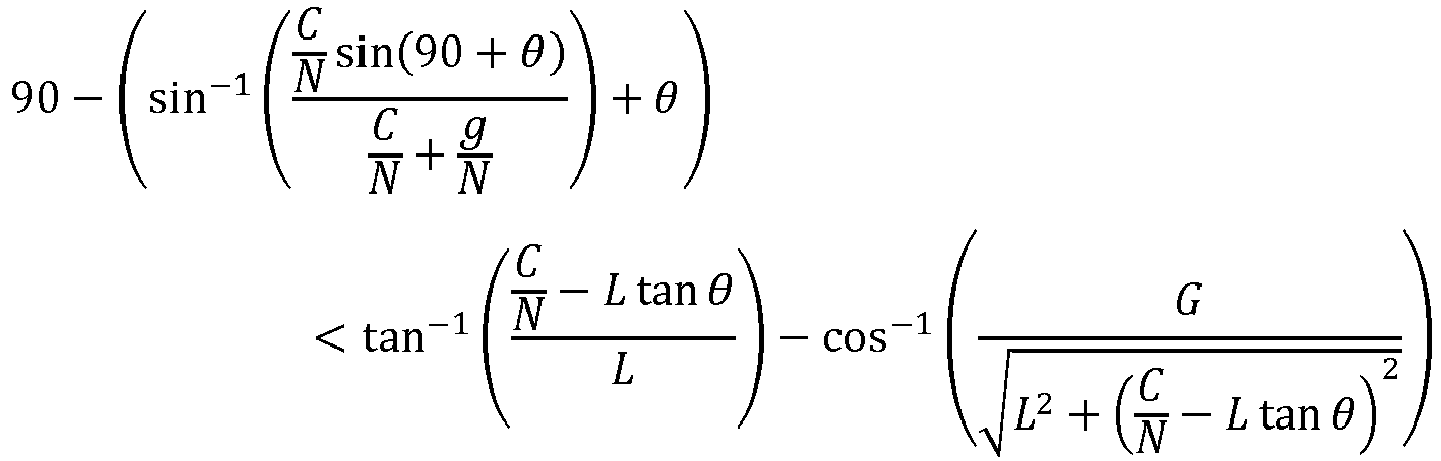
- the front and rear surfaces of the casing and the platforms of the stator vanes may be configured such that the following inequality is satisfied: 90 ⁇ sin ⁇ 1 C N sin 90 + ⁇ C N + g N + ⁇ ⁇ tan ⁇ 1 C N ⁇ L tan ⁇ L ⁇ cos ⁇ 1 G L 2 C N ⁇ L tan ⁇ 2
- ⁇ represents a scarf angle of the platforms of the stator vanes
- N represents the number of stator vanes received within the slot
- L represents the axial lengths of the platforms
- C represents the circumference of the casing at an outer radial surface of the platforms
- g represents the total circumferential clearance when the platforms are in their unrotated positions
- G represents the axial casing gap.
- the platforms of each of the stator vanes may have a scarf angle which is non-zero.
- Each of the scarf angles may be between 12 and 30 degrees.
- Each of the scarf angles may be between 18 and 21 degrees.
- a single aerofoil may extend from the platform of each of the plurality of stator vanes.
- the platform of at least one of the plurality of stator vanes may be pivotally connected to the casing.
- the platform of the at least one of the plurality of stator vanes may be pivotally connected to the casing at an upstream portion of the platform.
- the casing may be a compressor casing and the stator vanes may be compressor stator vanes.
- a method of manufacturing a casing assembly for a gas turbine engine comprising: a casing comprising a slot defined by a front surface and a rear surface, the front surface and the rear surface being spaced apart by an axial casing gap; and a plurality of stator vanes each comprising a platform which is received within the slot, the platform having an axial length and a circumferential length; wherein the circumferential lengths of the platforms define a total circumferential length which is less than the circumference of the casing at an outer radial surface of the platforms and so defines a circumferential clearance; wherein the axial length of each of the platforms is less than the axial casing gap and so defines an axial clearance; wherein the circumferential and axial clearances allow the platforms of the stator vanes to rotate within the slot, with rotation of the platforms from an unrotated position reducing the circumferential and axial clearance; wherein the method comprises configuring the front and rear surfaces of the casing
- the front and rear surfaces of the casing and the platforms of the stator vanes may be configured such that the following inequality is satisfied: 90 ⁇ sin ⁇ 1 C N sin 90 + ⁇ C N + g N + ⁇ ⁇ tan ⁇ 1 C N ⁇ L tan ⁇ L ⁇ cos ⁇ 1 G L 2 C N ⁇ L tan ⁇ 2
- ⁇ represents a scarf angle of the platforms of the stator vanes
- N represents the number of stator vanes received within the slot
- L represents the axial lengths of the platforms
- C represents the circumference of the casing at an outer radial surface of the platforms
- g represents the total circumferential clearance when the platforms are in their unrotated positions
- G represents the axial casing gap.
- Figure 1 shows a ducted fan gas turbine engine 10 (in particular a high bypass ratio turbofan) having a principal and rotational axis X-X.
- the engine comprises, in axial flow series, an air intake 11, a propulsive fan 12, an intermediate pressure compressor 13, a high-pressure compressor 14, combustion equipment 15, a high-pressure turbine 16, an intermediate pressure turbine 17, a low-pressure turbine 18 and a core engine exhaust nozzle 19.
- the intermediate pressure compressor 13 and the high-pressure compressor 14 are axial compressors of a core flow through the engine (core compressors).
- a nacelle 21 generally surrounds the engine 10 and defines the intake 11, a bypass duct 22 and a bypass exhaust nozzle 23.
- air entering the intake 11 is accelerated by the fan 12 (which is also a compressor) to produce two air flows: a first air flow A into the intermediate pressure compressor 13 and a second air flow B which passes through the bypass duct 22 to provide propulsive thrust.
- the intermediate pressure compressor 13 compresses the air flow A directed into it before delivering that air to the high pressure compressor 14, where further compression takes place.
- the compressed air exhausted from the high-pressure compressor 14 is directed into the combustion equipment 15 where it is mixed with fuel and the mixture is combusted.
- the resultant hot combustion products then expand through, and thereby drive, the high, intermediate and low-pressure turbines 16, 17, 18 before being exhausted through the nozzle 19 to provide additional propulsive thrust.
- the high, intermediate and low-pressure turbines respectively drive the high and intermediate pressure compressors 14, 13 and the fan 12 by suitable interconnecting shafts.
- FIG 2 shows a cutaway view of the intermediate pressure compressor 13 of Figure 1 .
- the compressor 13 comprises a stationary annular compressor casing 24 and a plurality of stator vanes 30 (i.e. stator blades 30) which together form a casing assembly.
- the longitudinal axis Y-Y of the compressor 13 is aligned with the principal and rotational axis X-X of the gas turbine engine 10.
- the plurality of circumferentially arranged stator vanes 30 are fixed to the compressor casing 24 by way of a plurality of annular slots 32.
- the plurality of annular slots 32 extend circumferentially around the longitudinal axis Y-Y and have T-shaped cross-sectional profiles.
- FIG. 3 shows a perspective view of a single stator vane 30.
- the stator vane 30 generally comprises a base 36, a first aerofoil 38 and a second aerofoil 40.
- Stator vanes 30 comprising a first aerofoil 38 and a second aerofoil 40 are commonly referred to as "welded doubles".
- the base 36 comprises a central platform 42 from which the first and second aerofoil 38, 40 extend.
- the stator vane 30 is a cantilevered stator vane, meaning that the first and second aerofoils 38, 40 are only supported from one end.
- the base 36 further comprises a front tang 44 and a rear tang 46 disposed on either side of the platform 42.
- a notch 48 is formed in the front tang 44 towards one end and extending inwards towards the central platform 42.
- a borescope hole 49 and a contiguous air offtake 51 extend through the platform 42, from a radially inner side of the platform 42 to a radially outer side of the platform 42.
- a slot 53 extends from one side of the platform 42 to the other.
- the front tangs 44 When installed within one of the slots 32, the front tangs 44 are disposed upstream of the rear tangs 46, and the first and second aerofoils 38, 40 extend towards the longitudinal axis Y-Y of the compressor 13.
- the direction extending from the upstream portion of the compressor casing 24 to the downstream direction of the compressor casing shall be referred to as the axial direction.
- the direction extending along the slot 32 in a direction perpendicular to the axial direction shall be referred to as the circumferential direction.
- the direction extending from the stator vane 30 to the longitudinal axis Y-Y of the compressor 13 shall be referred to as the radial direction.
- the terms axial, circumferential and radial shall be used to specify directions of measurements (e.g.
- stator vanes 30 are in an unrotated position, unless stated otherwise. Rotation of the stator vanes 30 occurs about an axis extending perpendicularly from the longitudinal axis Y-Y of the compressor 13 (i.e. about a radial axis).
- Figure 4 shows a side view of the stator vane 30.
- the radial thickness of the front tang 44 and the rear tang 46 is less than the radial thickness of the platform 42.
- the base 36 has a T-shaped cross-sectional profile, which fits within one of the T-shaped annular slots 32.
- the front and rear tangs 44, 46 of the stator vanes 30 prevent the stator vanes 30 exiting the slot 32 towards the axis Y-Y.
- the front tang 44 has an axial length A2 and the platform 42 has an axial length L.
- Figure 5 shows a plan view of the stator vane 30 in isolation as viewed from the longitudinal axis Y-Y of the compressor 13.
- the base 36 is rhomboid-shaped. That is, the base 36 has four sides (namely a front edge 52, a rear edge 54, a first side edge 56 and a second side edge 58) comprising two pairs of parallel sides (i.e. the front edge 52 and the rear edge 54 are parallel, and the first side edge 56 and the second side edge 58 are parallel), with adjacent sides of unequal length (the front edge 52 and the rear edge 54 are shorter than the first side edge 56 and the second side edge 58) and angles between the sides that are non-right angled.
- the scarf angle ⁇ of the base 36 is defined as the angle between the axial direction and the first or second side edge 56, 58 when the stator vane 30 is in an unrotated position.
- the scarf angle ⁇ is alternatively defined as either 90 degrees minus the angle in degrees between the front edge 52 and the first side edge 56, or 90 degrees minus the angle in degrees between the rear edge 54 and the second side edge 58.
- the grading width A1 of the base 36 is defined as the distance between the first side edge 56 and the second side edge 58 in a direction perpendicular to the first side edge 56 and the second side edge 58 (i.e. the minimum distance between the first and second side edges 56, 58).
- the vane width w is defined as the circumferential component of the width of the platform 42.
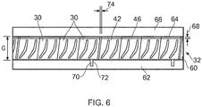
- FIG. 6 shows a plurality of the stator vanes 30 installed within one of the slots 32.
- the stator vanes 30 are shown without borescope holes 49 and air offtakes 51.
- a front anti-fret liner 60 is disposed within the slot 32, adjacent a front wall 62 of the slot 32.
- a rear anti-fret liner 64 is disposed within the slot 32, adjacent a rear wall 66 of the slot 32.
- Inner surfaces (i.e. the adjacent, opposing surfaces) of the front and rear anti-fret liners 60, 64 are spaced apart by an axial casing gap G.
- the axial casing gap G is greater than the axial length L of the platform 42. Accordingly, an axial clearance 68 is provided between the platform 42 and the rear anti-fret liner 64.
- each of the stator vanes 30 is retained behind the front wall 62 of the slot 32, and the rear tang 46 of each of the stator vanes 30 is retained behind the rear wall 66 of the slot 32.
- the platform 42 of each of the stator vanes 30 abuts the front anti-fret liner 60 such that the front tang 44 of each of the stator vanes 30 is hidden from view.
- a portion of the each of the rear tangs 46 is shown in Figure 6 , adjacent the rear anti-fret liner 64.
- a total of eight complete stator vanes 30 are shown.
- a series of notches 72 are provided in the front wall 62, adjacent the slot 32. Every fourth stator vane 30 (hereinafter referred to as a stop vane 30) is secured to the slot 32 via one of the notches 72.
- a stop feature 70 extends through the notch 72, into a corresponding notch 48 of the respective stop vane 30.
- the stop features 70 pivotally secure the lower right corners of the stop vanes 30 to the casing 24, which prevents the stop vanes 30 moving along the slot 32 in a circumferential direction.
- Three stator vanes 30 (hereinafter referred to as unsecured stator vanes 30) are disposed between adjacent pairs of stop vanes 30. In contrast to the stop vanes 30, the unsecured stator vanes 30 are not secured to the slot 32 by way of stop features 70.
- the notches 72 are spaced along the front wall 62 such that the sum of the vane widths w of the unsecured stator vanes 30 disposed between adjacent stop vanes 30 is less than the circumferential distance along the slot 32 between the adjacent stop vanes 30. Accordingly, circumferential clearances 74 are formed between the stator vanes 30. In the arrangement shown in Figure 6 , the stator vanes 30 are displaced as far right as possible. Accordingly, the circumferential clearance 74 is formed between each of the stop vanes 30 and the unsecured stator vane 30 positioned directly to its right. This circumferential clearance 74 may however be formed between any of the adjacent stator vanes 30 or be formed by more than one adjacent pair of stator vanes 30 in a run of four stator vanes 30. The sum of all of the circumferential clearances 74 around the slot 32 is referred to as the total circumferential clearance, and the total circumferential clearance when the platforms are in an unrotated position is designated by g (not shown in the Figures).
- the axial clearance 68 and circumferential clearances 74 manage thermal mismatch between the stator vanes 30 and the surrounding components of the compressor casing 24 (i.e. mismatch due to thermal expansion of the stator vanes 30 and the compressor casing 24).
- the stator vanes 30 will thermally expand more than the compressor casing 24, since the stator vanes 30 are heated by heated compressed gas flow whereas the compressor casing 24 is cooled by the second air flow B (i.e. the bypass air or non-core flow).
- the compressor casing 24 is typically made of a corrosion-resistant steel such as Jethete® whereas the stator vanes 30 are typically made of a nickel-base alloy such as Inconel® 718, which has a higher thermal expansion coefficient.
- stator vanes 30 i.e. both the stop vanes 30 and the unsecured stator vanes 30
- stator vanes 30 are able to rotate within the slot 32 (i.e. rotate about an axis extending perpendicularly from the longitudinal axis Y-Y of the compressor 13).
- the notches 48 of the stop vanes 30 are provided towards a right hand side of the front tang 44. Accordingly, rotational movement of the stop vanes 30 in a clockwise direction (as viewed from Figure 6 ) is promoted, whereas rotational movement of the stop vanes 30 in an anti-clockwise direction is inhibited.
- stator vanes 30 will naturally tend to rotate consistently in a clockwise direction due to the aerodynamic forces acting on the vane platform 42 in a clockwise direction.
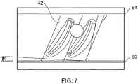
- a single unsecured stator vane 30 is shown in a rotated position in Figure 7 .
- the amount of rotation ⁇ of a stator vane 30 can be defined as the amount of rotation of the stator vane 30 relative to an unrotated position (i.e. a position in which the edge of the platform 42 adjacent the front anti-fret liner 60 is parallel to the front anti-fret liner 60).
- the amount of rotation ⁇ of the stator vane 30 is such that the lower-right corner of the platform 42 abuts the front anti-fret liner 60 and the upper-left corner of the platform 42 abuts the rear anti-fret liner 64.
- the axial clearance 68 is fully consumed.
- the stator vane 30 is therefore unable to rotate any further in the clockwise direction due to the front and rear anti-fret liners 60, 64. This is referred to as axial locking.
- each unsecured stator vane 30 and each stop vane 30 may exhibit rotational movement.
- the configuration shown in Figure 6 prevents axial locking, whilst allowing circumferential locking. Circumferential locking occurs when a stator vane 30 is unable to rotate any further away from the unrotated position due to adjacent stator vanes 30 preventing further rotation. Once circumferential locking has occurred, the stator vanes 30 are able to unlock by rotating in the opposite direction. Circumferential locking is preferential over axial locking, since axial locking risks the stator vanes 30 becoming permanently or semi-permanently fixed to the front and rear anti-fret liners 60, 64. Further, axial locking results in wear of the anti-fret liners 60, 64.
- stator vanes 30 and compressor casing 24 In order to prevent axial locking of the stator vanes 30 whilst allowing circumferential locking, the stator vanes 30 and compressor casing 24 must have specific dimensions, as explained with reference to Figures 8 , 9 and 10 .
- Figure 8 shows a geometric representation of a stator vane 30 comprising a platform 42, a front tang 44 and a rear tang 46. Dashed lines are used to highlight geometric features of the stator vane 30. For clarity, the first aerofoil 38 and the second aerofoil 40 are not shown in Figure 8 .
- the major diagonal of the front tang 44 is shown in dashed lines, connecting the lower left corner of the front tang 44 to the upper right corner of the front tang 44.
- the major diagonal is the line segment joining the two opposing vertices of the front tang 44 that are furthest apart.
- the length of the major diagonal of the front tang 44 is denoted by R and the circumferential component of the major diagonal of the front tang 44 is denoted by X.
- ⁇ is the angle formed between the major diagonal of the front tang 44 and the axial direction.
- FIG. 9 shows the stator vane 30 rotated about the upper right corner of the front tang 44 in a clockwise direction.
- the unrotated stator vane 30 (as shown in Figure 8 ) is also shown in phantom.
- the circumferential component of the displacement of the lower left corner of the front tang 44 when the stator vane 30 is rotated by an angle ⁇ in a clockwise direction is denoted by E1.
- X ⁇ is the circumferential component of the major diagonal of the front tang 44 when the stator vane 30 is not rotated and X ⁇ + ⁇ is the circumferential component of the major diagonal of the front tang 44 when the stator vane 30 is rotated.
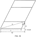
- FIG. 10 shows the stator vane 30 in its unrotated position, as per Figure 8 .
- E2 the circumferential component of the major diagonal of the front tang 44 when the stator vane 30 is not rotated.
- v is the circumferential component of the width of the front tang 44
- A2 is the axial length of the front tang 44 when the stator vane 30 is unrotated.
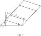
- FIG 11 shows the stator vane 30 rotated about the upper right corner of the front tang 44 in a clockwise direction, as per Figure 9 .
- the axial distance moved by the lower left corner of the front tang 44 when the stator vane is rotated by an angle ⁇ is denoted by E3.
- D The circumferential distance moved by the lower left corner of the front tang 44 when the stator vane is rotated by an angle ⁇ is denoted by D.
- Figure 12 shows the stator vane 30 in its unrotated position, as per Figures 8 and 10 .
- the inner edges of the front and rear anti-fret liners 60, 64 are shown in dashed lines.
- the minor diagonal of the platform 42 is likewise shown in dashed lines.
- the minor diagonal of the platform 42 is the diagonal formed between the upper left corner of the platform 42 and the lower right corner of the platform 42 (i.e. the line segment joining the two opposing vertices of the platform 42 that are closest together).
- the minor diagonal of the platform 42 is also shown in dashed lines in a rotated position, where the stator vane 30 is rotated about the upper right corner of the front tang 44 in a clockwise direction by an angle ⁇ so that it contacts both the front and rear anti-fret liners 60, 64.
- the circumferential component of the minor diagonal of the platform 42 when the stator vane 30 is unrotated is denoted by W eff .
- D Mi denotes the length of the minor diagonal of the platform 42.
- the axial distance between the upper and lower edges of the platform 42 i.e. the minimum distance between the upper and lower edges of the platform 42
- L The angle formed between the minor diagonal of the platform 42 and the axial direction when the stator vane 30 is in its unrotated position.
- Circumferential locking occurs when the following condition is met, using ⁇ as defined by equation 13: g ⁇ E 1 + E 4
- stator vanes 30 lock circumferentially rather than axially, the following condition must be met: angle at which stator vanes lock circumferentially ⁇ angle at which stator vanes lock axially
- C is the circumference of the circle formed by the radially outer surfaces of the platforms 42 and N is the number of stator vanes 30 within the annular slot 32.
- stator vanes 30 Provided the above condition is met, as the angle of rotation ⁇ of the stator vanes 30 increases, the total circumferential clearance g is consumed before the axial clearance 68 is consumed. Once the stator vanes 30 are circumferentially locked, they cannot rotate any further from the unrotated position and cannot therefore axially lock. Any additional circumferential expansion of the stator vanes 30 due to thermal expansion will cause the stator vanes 30 to rotate at least part way back to their unrotated position.
- stator vane 30 comprises a first aerofoil 38 and a second aerofoil 40 (i.e. that the stator vanes 30 are "welded doubles")
- they may alternatively comprise a single aerofoil or more than two aerofoils.
- Stator vanes 30 comprising more than one aerofoil may be manufactured by fixing multiple stator vanes together, for example by welding.
- Stator vanes 30 comprising a single aerofoil do not require a fixing process and may therefore be less expensive to produce and quicker to manufacture than alternative arrangements.
- Stator vanes 30 comprising a single aerofoil are also less likely to introduce non-conformances that can lead to build issues.
- every fourth stator vane 30 is a stop vane 30
- any proportion of the stator vanes 30 may be stop vanes 30.
- every second or sixth stator vane 30 may be a stop vane 30.
- the stator vanes 30 shown in the Figures have a variety of different scarf angles ⁇ .
- the stator vanes 30 are shown as having a scarf angle ⁇ of approximately 20 degrees in Figure 5 , approximately 10 degrees in Figure 6 and approximately 25 degrees in Figures 8 to 12 .
- These values of scarf angles ⁇ are for illustrative purposes only, however any value of scarf angle ⁇ that meets the conditions specified by the inequality of equation 16 may be used.
- the scarf angle ⁇ may instead be 19 or 20 degrees, be between 18 and 21 degrees or be between 12 and 30 degrees, provided that the conditions specified by the inequality of equation 16 are met. It has been found that an increase in scarf angle ⁇ increases the likelihood of circumferential locking whilst reducing the likelihood of axial locking.
- a 0.3 degree increase in scarf angle ⁇ in one example is sufficient to compensate for the increase in permissible rotation from the axial clearance 68 in going from stator vanes 30 comprising a first aerofoil 38 and a second aerofoil 40 (i.e. "welded doubles") to stator vanes 30 comprising only a single aerofoil.
- the potential increase in surge margin penalty due to an increase in vane rotation is mitigated by encouraging the stator vanes 30 to cease rotating due to circumferential locking (at a lower angle) instead of the axial clearance 68.
- a minimum scarf angle ⁇ of 10.3 degrees will mitigate the effect to the surge margin of going from welded doubles to stator vanes 30 comprising only a single aerofoil for the given stage of vanes. Therefore, a scarf angle ⁇ of approximately 11 degrees is suitable for minimising the size of the platform 42 by fitting the platform 42 to the angle of the aerofoil or aerofoils.
- the base 36 is rhomboid-shaped.
- the base 36 may instead be rhombus-shaped.
- the base 36 may be rectangular-shaped or square-shaped, in which case the scarf angle ⁇ is zero.
- the axial casing gap G is defined as the distance between the inner surfaces (i.e. the adjacent surfaces) of the the front wall 62 and the rear wall 66 of the slot 32 (i.e. the maximum axial distance that the platform 42 can occupy).
- stator vanes 30 are compressor stator vanes (i.e. that they are fixed to the compressor casing 24), they may alternatively be turbine stator vanes (i.e. be fixed to a casing of the high-pressure turbine 16, intermediate pressure turbine 17 or low-pressure turbine 18).
- the structure of the turbine casing may substantially correspond to the structure of the compressor casing 24.
- turboprop engine may be a TP400®, for example.
- the gas turbine engine may be used in an aircraft.
- the gas turbine engine may alternatively be used for other applications, such as marine applications.
- cooling can be effected by ambient air, or, depending on the set-up, bleed offtake air.
- one or more corners of the platform 42 or tangs 44, 46 may be rounded. This results in a corresponding reduction in the length of the major and minor diagonals of the respective platforms 42 and tangs 44, 46.
- the notches 48 of the stop vanes 30 are provided towards a right hand side of the front tang 44, the notches 48 may be provided anywhere along the front tang 44.
- stator vane 30 is a cantilevered stator vane, it may instead be a shrouded stator vane.
Landscapes
- Engineering & Computer Science (AREA)
- Mechanical Engineering (AREA)
- General Engineering & Computer Science (AREA)
- Structures Of Non-Positive Displacement Pumps (AREA)
Abstract
Description
- This disclosure relates to a casing assembly and a method of manufacturing a casing assembly for a gas turbine engine.
- Existing gas turbine engines typically comprise a compressor casing having a slot, which extends circumferentially around a central axis of the gas turbine engine. The slot receives a plurality of stator vanes. In order to allow for thermal expansion of the stator vanes and compressor casing during operation of the gas turbine engine, the stator vanes are spaced apart along the slot using a circumferential locking method, and an axial gap is provided between a platform of the stator vane and the interior surfaces of the slot. This does however allow the stator vanes to rotate within the slot. In order to limit such rotational movement, axial locking of the stator vanes at low angles is encouraged by combining multiple vanes together such that their circumferential width is increased and such that they lock against the interior edges of the slots at a smaller angle. However, combining multiple vanes together can introduce non-conformance, cause build issues, increase cost and increase manufacture time.
- It is therefore desirable to provide an improved gas turbine engine and method of manufacturing a stator vane for a gas turbine engine that overcome these issues.
- According to a first aspect of the disclosure there is provided a casing assembly for a gas turbine engine, the casing assembly comprising: a casing comprising a slot defined by a front surface and a rear surface, the front surface and the rear surface being spaced apart by an axial casing gap; and a plurality of stator vanes each comprising a platform and at least one aerofoil extending from the platform, the platform being received within the slot and having an axial length and a circumferential length; wherein the circumferential lengths of the platforms define a total circumferential length which is less than the circumference of the casing at an outer radial surface of the platforms and so defines a circumferential clearance; wherein the axial length of each of the platforms is less than the axial casing gap and so defines an axial clearance; wherein the circumferential and axial clearances allow the platforms of the stator vanes to rotate within the slot, with rotation of the platforms from an unrotated position reducing the circumferential and axial clearance; wherein the front and rear surfaces of the casing and the platforms of the stator vanes are configured such that rotation of the platforms from the unrotated position entirely consumes the circumferential clearance so that adjacent platforms abut against one another and prevent further rotation of the platforms while maintaining an axial clearance. Although it has been described that the front and rear surfaces are defined by front and rear anti-fret liners, in alternative arrangements in which front and rear anti-fret liners are not provided, the front and rear surfaces may be defined by front and rear walls of the slot.
- The front and rear surfaces of the casing and the platforms of the stator vanes may be configured such that the following inequality is satisfied:

- The platforms of each of the stator vanes may have a scarf angle which is non-zero.
- Each of the scarf angles may be between 12 and 30 degrees.
- Each of the scarf angles may be between 18 and 21 degrees.
- A single aerofoil may extend from the platform of each of the plurality of stator vanes.
- The platform of at least one of the plurality of stator vanes may be pivotally connected to the casing.
- The platform of the at least one of the plurality of stator vanes may be pivotally connected to the casing at an upstream portion of the platform.
- The casing may be a compressor casing and the stator vanes may be compressor stator vanes.
- According to a second aspect of the disclosure there is provided a method of manufacturing a casing assembly for a gas turbine engine, the casing assembly comprising: a casing comprising a slot defined by a front surface and a rear surface, the front surface and the rear surface being spaced apart by an axial casing gap; and a plurality of stator vanes each comprising a platform which is received within the slot, the platform having an axial length and a circumferential length; wherein the circumferential lengths of the platforms define a total circumferential length which is less than the circumference of the casing at an outer radial surface of the platforms and so defines a circumferential clearance; wherein the axial length of each of the platforms is less than the axial casing gap and so defines an axial clearance; wherein the circumferential and axial clearances allow the platforms of the stator vanes to rotate within the slot, with rotation of the platforms from an unrotated position reducing the circumferential and axial clearance; wherein the method comprises configuring the front and rear surfaces of the casing and/or the platforms of the stator vanes such that rotation of the platforms from the unrotated position entirely consumes the circumferential clearance so that adjacent platforms abut against one another and prevent further rotation of the platforms while maintaining an axial clearance.
- The front and rear surfaces of the casing and the platforms of the stator vanes may be configured such that the following inequality is satisfied:
- For a better understanding of the invention and to show more clearly how it may be carried into effect, reference will now be made, by way of example, to the accompanying drawings, in which:
-
Figure 1 shows a cross-sectional view of a gas turbine engine; -
Figure 2 shows a cutaway perspective view of a compressor casing; -
Figure 3 shows a perspective view of a stator vane; -
Figure 4 shows a side view of the stator vane; -
Figure 5 shows a plan view of the stator vane; -
Figure 6 shows a plan view of a row of the stator vanes arranged in unrotated positions within a slot; -
Figure 7 shows a plan view of a stator vane arranged in a rotated position within a slot; -
Figure 8 shows a first geometric representation of a stator vane in plan view, with the stator vane shown in an unrotated position; -
Figure 9 shows a second geometric representation of the stator vane in plan view, with the stator vane shown in a rotated and unrotated position; -
Figure 10 shows a third geometric representation of the stator vane in plan view, with the stator vane shown in an unrotated position; -
Figure 11 shows a fourth geometric representation of the stator vane in plan view, with the stator vane shown in a rotated position; and -
Figure 12 shows a fifth geometric representation of the stator vane in plan view, with the stator vane shown in an unrotated position. -
Figure 1 shows a ducted fan gas turbine engine 10 (in particular a high bypass ratio turbofan) having a principal and rotational axis X-X. The engine comprises, in axial flow series, anair intake 11, apropulsive fan 12, anintermediate pressure compressor 13, a high-pressure compressor 14,combustion equipment 15, a high-pressure turbine 16, anintermediate pressure turbine 17, a low-pressure turbine 18 and a coreengine exhaust nozzle 19. Theintermediate pressure compressor 13 and the high-pressure compressor 14 are axial compressors of a core flow through the engine (core compressors). Anacelle 21 generally surrounds theengine 10 and defines theintake 11, abypass duct 22 and abypass exhaust nozzle 23. - During operation, air entering the
intake 11 is accelerated by the fan 12 (which is also a compressor) to produce two air flows: a first air flow A into theintermediate pressure compressor 13 and a second air flow B which passes through thebypass duct 22 to provide propulsive thrust. Theintermediate pressure compressor 13 compresses the air flow A directed into it before delivering that air to thehigh pressure compressor 14, where further compression takes place. - The compressed air exhausted from the high-
pressure compressor 14 is directed into thecombustion equipment 15 where it is mixed with fuel and the mixture is combusted. The resultant hot combustion products then expand through, and thereby drive, the high, intermediate and low-pressure turbines nozzle 19 to provide additional propulsive thrust. The high, intermediate and low-pressure turbines respectively drive the high andintermediate pressure compressors fan 12 by suitable interconnecting shafts. -
Figure 2 shows a cutaway view of theintermediate pressure compressor 13 ofFigure 1 . Thecompressor 13 comprises a stationaryannular compressor casing 24 and a plurality of stator vanes 30 (i.e. stator blades 30) which together form a casing assembly. The longitudinal axis Y-Y of thecompressor 13 is aligned with the principal and rotational axis X-X of thegas turbine engine 10. The plurality of circumferentially arrangedstator vanes 30 are fixed to thecompressor casing 24 by way of a plurality ofannular slots 32. The plurality ofannular slots 32 extend circumferentially around the longitudinal axis Y-Y and have T-shaped cross-sectional profiles. -
Figure 3 shows a perspective view of asingle stator vane 30. Thestator vane 30 generally comprises abase 36, afirst aerofoil 38 and asecond aerofoil 40.Stator vanes 30 comprising afirst aerofoil 38 and asecond aerofoil 40 are commonly referred to as "welded doubles". Thebase 36 comprises acentral platform 42 from which the first andsecond aerofoil stator vane 30 is a cantilevered stator vane, meaning that the first andsecond aerofoils base 36 further comprises afront tang 44 and arear tang 46 disposed on either side of theplatform 42. Anotch 48 is formed in thefront tang 44 towards one end and extending inwards towards thecentral platform 42. Aborescope hole 49 and acontiguous air offtake 51 extend through theplatform 42, from a radially inner side of theplatform 42 to a radially outer side of theplatform 42. Aslot 53 extends from one side of theplatform 42 to the other. - When installed within one of the
slots 32, thefront tangs 44 are disposed upstream of therear tangs 46, and the first andsecond aerofoils compressor 13. Hereinafter, for efficiency, the direction extending from the upstream portion of thecompressor casing 24 to the downstream direction of the compressor casing shall be referred to as the axial direction. The direction extending along theslot 32 in a direction perpendicular to the axial direction shall be referred to as the circumferential direction. The direction extending from thestator vane 30 to the longitudinal axis Y-Y of thecompressor 13 shall be referred to as the radial direction. The terms axial, circumferential and radial shall be used to specify directions of measurements (e.g. circumferential length, radial thickness) and components of measurement (e.g. the axial component of the minor diagonal). These terms are generally used to specify the measurements and components of measurement when thestator vanes 30 are in an unrotated position, unless stated otherwise. Rotation of thestator vanes 30 occurs about an axis extending perpendicularly from the longitudinal axis Y-Y of the compressor 13 (i.e. about a radial axis). -
Figure 4 shows a side view of thestator vane 30. The radial thickness of thefront tang 44 and therear tang 46 is less than the radial thickness of theplatform 42. Accordingly, thebase 36 has a T-shaped cross-sectional profile, which fits within one of the T-shapedannular slots 32. The front andrear tangs stator vanes 30 prevent thestator vanes 30 exiting theslot 32 towards the axis Y-Y. Thefront tang 44 has an axial length A2 and theplatform 42 has an axial length L. -
Figure 5 shows a plan view of thestator vane 30 in isolation as viewed from the longitudinal axis Y-Y of thecompressor 13. Thebase 36 is rhomboid-shaped. That is, thebase 36 has four sides (namely afront edge 52, arear edge 54, afirst side edge 56 and a second side edge 58) comprising two pairs of parallel sides (i.e. thefront edge 52 and therear edge 54 are parallel, and thefirst side edge 56 and thesecond side edge 58 are parallel), with adjacent sides of unequal length (thefront edge 52 and therear edge 54 are shorter than thefirst side edge 56 and the second side edge 58) and angles between the sides that are non-right angled. The scarf angle θ of thebase 36 is defined as the angle between the axial direction and the first orsecond side edge stator vane 30 is in an unrotated position. The scarf angle θ is alternatively defined as either 90 degrees minus the angle in degrees between thefront edge 52 and thefirst side edge 56, or 90 degrees minus the angle in degrees between therear edge 54 and thesecond side edge 58. The grading width A1 of thebase 36 is defined as the distance between thefirst side edge 56 and thesecond side edge 58 in a direction perpendicular to thefirst side edge 56 and the second side edge 58 (i.e. the minimum distance between the first and second side edges 56, 58). The vane width w is defined as the circumferential component of the width of theplatform 42. -
Figure 6 shows a plurality of thestator vanes 30 installed within one of theslots 32. For clarity, thestator vanes 30 are shown without borescope holes 49 andair offtakes 51. A frontanti-fret liner 60 is disposed within theslot 32, adjacent afront wall 62 of theslot 32. Likewise, a rearanti-fret liner 64 is disposed within theslot 32, adjacent arear wall 66 of theslot 32. Inner surfaces (i.e. the adjacent, opposing surfaces) of the front and rearanti-fret liners platform 42. Accordingly, an axial clearance 68 is provided between theplatform 42 and the rearanti-fret liner 64. - The
front tang 44 of each of thestator vanes 30 is retained behind thefront wall 62 of theslot 32, and therear tang 46 of each of thestator vanes 30 is retained behind therear wall 66 of theslot 32. InFigure 6 , theplatform 42 of each of thestator vanes 30 abuts the frontanti-fret liner 60 such that thefront tang 44 of each of thestator vanes 30 is hidden from view. A portion of the each of therear tangs 46 is shown inFigure 6 , adjacent the rearanti-fret liner 64. - A total of eight
complete stator vanes 30 are shown. A series ofnotches 72 are provided in thefront wall 62, adjacent theslot 32. Every fourth stator vane 30 (hereinafter referred to as a stop vane 30) is secured to theslot 32 via one of thenotches 72. Specifically, astop feature 70 extends through thenotch 72, into a correspondingnotch 48 of therespective stop vane 30. The stop features 70 pivotally secure the lower right corners of thestop vanes 30 to thecasing 24, which prevents thestop vanes 30 moving along theslot 32 in a circumferential direction. Three stator vanes 30 (hereinafter referred to as unsecured stator vanes 30) are disposed between adjacent pairs of stop vanes 30. In contrast to the stop vanes 30, theunsecured stator vanes 30 are not secured to theslot 32 by way of stop features 70. - The
notches 72 are spaced along thefront wall 62 such that the sum of the vane widths w of theunsecured stator vanes 30 disposed betweenadjacent stop vanes 30 is less than the circumferential distance along theslot 32 between the adjacent stop vanes 30. Accordingly,circumferential clearances 74 are formed between the stator vanes 30. In the arrangement shown inFigure 6 , thestator vanes 30 are displaced as far right as possible. Accordingly, thecircumferential clearance 74 is formed between each of thestop vanes 30 and theunsecured stator vane 30 positioned directly to its right. Thiscircumferential clearance 74 may however be formed between any of theadjacent stator vanes 30 or be formed by more than one adjacent pair ofstator vanes 30 in a run of fourstator vanes 30. The sum of all of thecircumferential clearances 74 around theslot 32 is referred to as the total circumferential clearance, and the total circumferential clearance when the platforms are in an unrotated position is designated by g (not shown in the Figures). - The axial clearance 68 and
circumferential clearances 74 manage thermal mismatch between thestator vanes 30 and the surrounding components of the compressor casing 24 (i.e. mismatch due to thermal expansion of thestator vanes 30 and the compressor casing 24). In use, thestator vanes 30 will thermally expand more than thecompressor casing 24, since thestator vanes 30 are heated by heated compressed gas flow whereas thecompressor casing 24 is cooled by the second air flow B (i.e. the bypass air or non-core flow). Further, thecompressor casing 24 is typically made of a corrosion-resistant steel such as Jethete® whereas thestator vanes 30 are typically made of a nickel-base alloy such as Inconel® 718, which has a higher thermal expansion coefficient. - As a result of the axial clearance 68 and the
circumferential clearances 74, the stator vanes 30 (i.e. both thestop vanes 30 and the unsecured stator vanes 30) are able to rotate within the slot 32 (i.e. rotate about an axis extending perpendicularly from the longitudinal axis Y-Y of the compressor 13). Thenotches 48 of thestop vanes 30 are provided towards a right hand side of thefront tang 44. Accordingly, rotational movement of thestop vanes 30 in a clockwise direction (as viewed fromFigure 6 ) is promoted, whereas rotational movement of thestop vanes 30 in an anti-clockwise direction is inhibited. Consequently, corresponding rotational movement of theunsecured stator vanes 30 is also encouraged and discouraged. In use, thestator vanes 30 will naturally tend to rotate consistently in a clockwise direction due to the aerodynamic forces acting on thevane platform 42 in a clockwise direction. - A single
unsecured stator vane 30 is shown in a rotated position inFigure 7 . The amount of rotation α of astator vane 30 can be defined as the amount of rotation of thestator vane 30 relative to an unrotated position (i.e. a position in which the edge of theplatform 42 adjacent the frontanti-fret liner 60 is parallel to the front anti-fret liner 60). - In the arrangement shown in
Figure 7 , the amount of rotation α of thestator vane 30 is such that the lower-right corner of theplatform 42 abuts the frontanti-fret liner 60 and the upper-left corner of theplatform 42 abuts the rearanti-fret liner 64. In the rotated position shown inFigure 7 , the axial clearance 68 is fully consumed. Thestator vane 30 is therefore unable to rotate any further in the clockwise direction due to the front and rearanti-fret liners - Although only a single
unsecured stator vane 30 is shown inFigure 7 , eachunsecured stator vane 30 and eachstop vane 30 may exhibit rotational movement. However, the configuration shown inFigure 6 prevents axial locking, whilst allowing circumferential locking. Circumferential locking occurs when astator vane 30 is unable to rotate any further away from the unrotated position due toadjacent stator vanes 30 preventing further rotation. Once circumferential locking has occurred, thestator vanes 30 are able to unlock by rotating in the opposite direction. Circumferential locking is preferential over axial locking, since axial locking risks thestator vanes 30 becoming permanently or semi-permanently fixed to the front and rearanti-fret liners anti-fret liners - In order to prevent axial locking of the
stator vanes 30 whilst allowing circumferential locking, thestator vanes 30 andcompressor casing 24 must have specific dimensions, as explained with reference toFigures 8 ,9 and10 . -
Figure 8 shows a geometric representation of astator vane 30 comprising aplatform 42, afront tang 44 and arear tang 46. Dashed lines are used to highlight geometric features of thestator vane 30. For clarity, thefirst aerofoil 38 and thesecond aerofoil 40 are not shown inFigure 8 . InFigure 8 , the vane width w is defined by the following equation:
- The major diagonal of the
front tang 44 is shown in dashed lines, connecting the lower left corner of thefront tang 44 to the upper right corner of thefront tang 44. The major diagonal is the line segment joining the two opposing vertices of thefront tang 44 that are furthest apart. The length of the major diagonal of thefront tang 44 is denoted by R and the circumferential component of the major diagonal of thefront tang 44 is denoted by X. X is defined by the following equation:
- Where β is the angle formed between the major diagonal of the
front tang 44 and the axial direction. -
Figure 9 shows thestator vane 30 rotated about the upper right corner of thefront tang 44 in a clockwise direction. The unrotated stator vane 30 (as shown inFigure 8 ) is also shown in phantom. The circumferential component of the displacement of the lower left corner of thefront tang 44 when thestator vane 30 is rotated by an angle α in a clockwise direction is denoted by E1. E1 is defined by the following equation:
- Where Xβ is the circumferential component of the major diagonal of the
front tang 44 when thestator vane 30 is not rotated and Xβ+α is the circumferential component of the major diagonal of thefront tang 44 when thestator vane 30 is rotated. - E1 is further defined by the following equation:

-
Figure 10 shows thestator vane 30 in its unrotated position, as perFigure 8 . InFigure 10 , the circumferential component of the major diagonal of thefront tang 44 when thestator vane 30 is not rotated is denoted by E2 (also previously referred to as X or Xβ). E2 is defined by the following equation:
- Where v is the circumferential component of the width of the
front tang 44, and A2 is the axial length of thefront tang 44 when thestator vane 30 is unrotated. - The length R of the major diagonal of the
front tang 44 is defined by the following equation:
- The angle β formed between the major diagonal and the axial direction is defined by the following equation:

-
Figure 11 shows thestator vane 30 rotated about the upper right corner of thefront tang 44 in a clockwise direction, as perFigure 9 . The axial distance moved by the lower left corner of thefront tang 44 when the stator vane is rotated by an angle α is denoted by E3. E3 is defined by the following equation:
- This equation can be rearranged as follows, in view of the first equation mentioned with reference to
Figure 8 :
- The circumferential distance moved by the lower left corner of the
front tang 44 when the stator vane is rotated by an angle α is denoted by D. D is approximated by the following equation:
- It thus follows that in a portion of the
compressor casing 24 having nadjacent stator vanes 30 rotated by an angle α, the circumferential gap E4n consumed by "shearing" of the adjacent stator vanes 30 (i.e. rotation of multiple adjacent stator vanes 30) is defined by the following equation:
-
Figure 12 shows thestator vane 30 in its unrotated position, as perFigures 8 and10 . The inner edges of the front and rearanti-fret liners platform 42 is likewise shown in dashed lines. The minor diagonal of theplatform 42 is the diagonal formed between the upper left corner of theplatform 42 and the lower right corner of the platform 42 (i.e. the line segment joining the two opposing vertices of theplatform 42 that are closest together). The minor diagonal of theplatform 42 is also shown in dashed lines in a rotated position, where thestator vane 30 is rotated about the upper right corner of thefront tang 44 in a clockwise direction by an angle α so that it contacts both the front and rearanti-fret liners - The circumferential component of the minor diagonal of the
platform 42 when thestator vane 30 is unrotated is denoted by Weff. DMi denotes the length of the minor diagonal of theplatform 42. The axial distance between the upper and lower edges of the platform 42 (i.e. the minimum distance between the upper and lower edges of the platform 42) is denoted by L. The angle formed between the minor diagonal of theplatform 42 and the axial direction when thestator vane 30 is in its unrotated position is denoted by γ. The casing gap G is defined by the following equation:
- This equation can be rearranged so as to define the angle of rotation α of the
stator vane 30 in terms of the angle γ, the casing gap G and the length DMi, as follows:
- Circumferential locking occurs when the following condition is met, using α as defined by equation 13:

- To ensure that the
stator vanes 30 lock circumferentially rather than axially, the following condition must be met:
- Based on the equations above, this condition is met when the following inequality is satisfied:

- Where C is the circumference of the circle formed by the radially outer surfaces of the
platforms 42 and N is the number ofstator vanes 30 within theannular slot 32. - Provided the above condition is met, as the angle of rotation α of the
stator vanes 30 increases, the total circumferential clearance g is consumed before the axial clearance 68 is consumed. Once thestator vanes 30 are circumferentially locked, they cannot rotate any further from the unrotated position and cannot therefore axially lock. Any additional circumferential expansion of thestator vanes 30 due to thermal expansion will cause thestator vanes 30 to rotate at least part way back to their unrotated position. - Although it has been described that the
stator vane 30 comprises afirst aerofoil 38 and a second aerofoil 40 (i.e. that thestator vanes 30 are "welded doubles"), they may alternatively comprise a single aerofoil or more than two aerofoils.Stator vanes 30 comprising more than one aerofoil may be manufactured by fixing multiple stator vanes together, for example by welding.Stator vanes 30 comprising a single aerofoil do not require a fixing process and may therefore be less expensive to produce and quicker to manufacture than alternative arrangements.Stator vanes 30 comprising a single aerofoil are also less likely to introduce non-conformances that can lead to build issues. - Although it has been described that every
fourth stator vane 30 is astop vane 30, any proportion of thestator vanes 30 may be stop vanes 30. For example, every second orsixth stator vane 30 may be astop vane 30. - For clarity, the
stator vanes 30 shown in the Figures have a variety of different scarf angles θ. For example, thestator vanes 30 are shown as having a scarf angle θ of approximately 20 degrees inFigure 5 , approximately 10 degrees inFigure 6 and approximately 25 degrees inFigures 8 to 12 . These values of scarf angles θ are for illustrative purposes only, however any value of scarf angle θ that meets the conditions specified by the inequality ofequation 16 may be used. For example, the scarf angle θ may instead be 19 or 20 degrees, be between 18 and 21 degrees or be between 12 and 30 degrees, provided that the conditions specified by the inequality ofequation 16 are met. It has been found that an increase in scarf angle θ increases the likelihood of circumferential locking whilst reducing the likelihood of axial locking. - As an example, it has been found that a 0.3 degree increase in scarf angle θ in one example is sufficient to compensate for the increase in permissible rotation from the axial clearance 68 in going from
stator vanes 30 comprising afirst aerofoil 38 and a second aerofoil 40 (i.e. "welded doubles") tostator vanes 30 comprising only a single aerofoil. The potential increase in surge margin penalty due to an increase in vane rotation is mitigated by encouraging thestator vanes 30 to cease rotating due to circumferential locking (at a lower angle) instead of the axial clearance 68. In some examples, it has been found that a minimum scarf angle θ of 10.3 degrees will mitigate the effect to the surge margin of going from welded doubles tostator vanes 30 comprising only a single aerofoil for the given stage of vanes. Therefore, a scarf angle θ of approximately 11 degrees is suitable for minimising the size of theplatform 42 by fitting theplatform 42 to the angle of the aerofoil or aerofoils. - It has been described that the
base 36 is rhomboid-shaped. However, thebase 36 may instead be rhombus-shaped. Alternatively, thebase 36 may be rectangular-shaped or square-shaped, in which case the scarf angle θ is zero. - Although it has been described that a front
anti-fret liner 60 and a rearanti-fret liner 64 are disposed within theslot 32, this need not be the case. When front and rearanti-fret liners front wall 62 and therear wall 66 of the slot 32 (i.e. the maximum axial distance that theplatform 42 can occupy). - Although it has been described that the
stator vanes 30 are compressor stator vanes (i.e. that they are fixed to the compressor casing 24), they may alternatively be turbine stator vanes (i.e. be fixed to a casing of the high-pressure turbine 16,intermediate pressure turbine 17 or low-pressure turbine 18). The structure of the turbine casing may substantially correspond to the structure of thecompressor casing 24. - Although it has been described that the abovementioned arrangement is for a high bypass ratio turbofan, it is suitable for any type of gas turbine engine. The abovementioned arrangement may be used in a turboprop engine, for example. The turboprop engine may be a TP400®, for example. The gas turbine engine may be used in an aircraft. The gas turbine engine may alternatively be used for other applications, such as marine applications.
- Although it has been described that the
compressor casing 24 is cooled by offtake air, in alternative arrangements, for example in turboprop engines such as the TP400®, cooling can be effected by ambient air, or, depending on the set-up, bleed offtake air. - Although not shown, one or more corners of the
platform 42 ortangs respective platforms 42 andtangs - Although it has been described that the
notches 48 of thestop vanes 30 are provided towards a right hand side of thefront tang 44, thenotches 48 may be provided anywhere along thefront tang 44. - Although it has been described that the
stator vane 30 is a cantilevered stator vane, it may instead be a shrouded stator vane. - The geometry of the examples discussed above may be mirrored such that features that are described as being on the left are on the right, and vice versa.
Claims (14)
- A casing assembly for a gas turbine engine (10), the casing assembly comprising:a casing (24) comprising a slot (32) defined by a front surface and a rear surface, the front surface and the rear surface being spaced apart by an axial casing gap; anda plurality of stator vanes (30) each comprising a platform (42) and at least one aerofoil (38, 40) extending from the platform, the platform being received within the slot and having an axial length and a circumferential length;wherein the circumferential lengths of the platforms define a total circumferential length which is less than the circumference of the casing at an outer radial surface of the platforms and so defines a circumferential clearance;wherein the axial length of each of the platforms is less than the axial casing gap and so defines an axial clearance;wherein the circumferential and axial clearances allow the platforms of the stator vanes to rotate within the slot, with rotation of the platforms from an unrotated position reducing the circumferential and axial clearance;wherein the front and rear surfaces of the casing and the platforms of the stator vanes are configured such that rotation of the platforms from the unrotated position entirely consumes the circumferential clearance so that adjacent platforms abut against one another and prevent further rotation of the platforms while maintaining an axial clearance.
- A casing assembly as claimed in claim 1, wherein the front and rear surfaces of the casing and the platforms of the stator vanes are configured such that the following inequality is satisfied:

- A casing assembly as claimed in claim 1 or 2, wherein the platforms of each of the stator vanes has a scarf angle which is non-zero.
- A casing assembly as claimed in claim 3, wherein each of the scarf angles is between 12 and 30 degrees.
- A casing assembly as claimed in claim 4, wherein each of the scarf angles is between 18 and 21 degrees.
- A casing assembly as claimed in any of the preceding claims, wherein a single aerofoil extends from the platform of each of the plurality of stator vanes.
- A casing assembly engine as claimed in any preceding claim, wherein the platform of at least one of the plurality of stator vanes is pivotally connected to the casing.
- A casing assembly as claimed in claim 7, wherein the platform of the at least one of the plurality of stator vanes is pivotally connected to the casing at an upstream portion of the platform.
- A casing assembly as claimed in any preceding claim, wherein the casing is a compressor casing and the stator vanes are compressor stator vanes.
- A gas turbine engine comprising a casing assembly as claimed in any preceding claim.
- A gas turbine engine as claimed in claim 10, wherein the gas turbine engine is a turboprop engine.
- A stator vane which, when received by a casing, forms a casing assembly as claimed in any one of claims 1 to 9 or a gas turbine engine as claimed in claim 10 or claim 11.
- A method of manufacturing a casing assembly for a gas turbine engine, the casing assembly comprising:a casing comprising a slot defined by a front surface and a rear surface, the front surface and the rear surface being spaced apart by an axial casing gap; anda plurality of stator vanes each comprising a platform which is received within the slot, the platform having an axial length and a circumferential length;wherein the circumferential lengths of the platforms define a total circumferential length which is less than the circumference of the casing at an outer radial surface of the platforms and so defines a circumferential clearance;wherein the axial length of each of the platforms is less than the axial casing gap and so defines an axial clearance;wherein the circumferential and axial clearances allow the platforms of the stator vanes to rotate within the slot, with rotation of the platforms from an unrotated position reducing the circumferential and axial clearance;wherein the method comprises configuring the front and rear surfaces of the casing and/or the platforms of the stator vanes such that rotation of the platforms from the unrotated position entirely consumes the circumferential clearance so that adjacent platforms abut against one another and prevent further rotation of the platforms while maintaining an axial clearance.
- A method as claimed in claim 13, wherein the front and rear surfaces of the casing and the platforms of the stator vanes are configured such that the following inequality is satisfied:

Applications Claiming Priority (1)
| Application Number | Priority Date | Filing Date | Title |
|---|---|---|---|
| GBGB1717577.9A GB201717577D0 (en) | 2017-10-26 | 2017-10-26 | A casing assembly and method of manufacturing a casing assembly for a gas trubine engine |
Publications (2)
| Publication Number | Publication Date |
|---|---|
| EP3477060A1 true EP3477060A1 (en) | 2019-05-01 |
| EP3477060B1 EP3477060B1 (en) | 2020-05-27 |
Family
ID=60580348
Family Applications (1)
| Application Number | Title | Priority Date | Filing Date |
|---|---|---|---|
| EP18197243.1A Active EP3477060B1 (en) | 2017-10-26 | 2018-09-27 | A casing assembly and method of manufacturing a casing assembly for a gas turbine engine |
Country Status (3)
| Country | Link |
|---|---|
| US (1) | US20190128129A1 (en) |
| EP (1) | EP3477060B1 (en) |
| GB (1) | GB201717577D0 (en) |
Cited By (1)
| Publication number | Priority date | Publication date | Assignee | Title |
|---|---|---|---|---|
| WO2022101029A1 (en) * | 2020-11-13 | 2022-05-19 | Rolls-Royce Deutschland Ltd & Co Kg | Guide vane wheel of a turbomachine |
Citations (5)
| Publication number | Priority date | Publication date | Assignee | Title |
|---|---|---|---|---|
| WO2001071165A1 (en) * | 2000-03-23 | 2001-09-27 | Alstom (Switzerland) Ltd | Fastening of the blades of a compression machine |
| EP2568120A2 (en) * | 2011-09-09 | 2013-03-13 | Rolls-Royce plc | A Turbine Engine Stator and Method of Assembly of the Same |
| WO2014062270A2 (en) * | 2012-08-27 | 2014-04-24 | United Technologies Corporation | Shiplap cantilevered stator |
| GB2547273A (en) * | 2016-02-15 | 2017-08-16 | Rolls Royce Plc | Stator vane |
| GB2551164A (en) * | 2016-06-08 | 2017-12-13 | Rolls Royce Plc | Stator vane |
-
2017
- 2017-10-26 GB GBGB1717577.9A patent/GB201717577D0/en not_active Ceased
-
2018
- 2018-09-26 US US16/142,312 patent/US20190128129A1/en not_active Abandoned
- 2018-09-27 EP EP18197243.1A patent/EP3477060B1/en active Active
Patent Citations (5)
| Publication number | Priority date | Publication date | Assignee | Title |
|---|---|---|---|---|
| WO2001071165A1 (en) * | 2000-03-23 | 2001-09-27 | Alstom (Switzerland) Ltd | Fastening of the blades of a compression machine |
| EP2568120A2 (en) * | 2011-09-09 | 2013-03-13 | Rolls-Royce plc | A Turbine Engine Stator and Method of Assembly of the Same |
| WO2014062270A2 (en) * | 2012-08-27 | 2014-04-24 | United Technologies Corporation | Shiplap cantilevered stator |
| GB2547273A (en) * | 2016-02-15 | 2017-08-16 | Rolls Royce Plc | Stator vane |
| GB2551164A (en) * | 2016-06-08 | 2017-12-13 | Rolls Royce Plc | Stator vane |
Cited By (1)
| Publication number | Priority date | Publication date | Assignee | Title |
|---|---|---|---|---|
| WO2022101029A1 (en) * | 2020-11-13 | 2022-05-19 | Rolls-Royce Deutschland Ltd & Co Kg | Guide vane wheel of a turbomachine |
Also Published As
| Publication number | Publication date |
|---|---|
| EP3477060B1 (en) | 2020-05-27 |
| US20190128129A1 (en) | 2019-05-02 |
| GB201717577D0 (en) | 2017-12-13 |
Similar Documents
| Publication | Publication Date | Title |
|---|---|---|
| US8707712B2 (en) | Gas turbine engine turbine vane airfoil profile | |
| US9115588B2 (en) | Gas turbine engine turbine blade airfoil profile | |
| US10060268B2 (en) | Turbine blade having film cooling hole arrangement | |
| US11549437B2 (en) | Combustor for gas turbine engine and method of manufacture | |
| US10480333B2 (en) | Turbine blade including balanced mateface condition | |
| US10443434B2 (en) | Turbine airfoil platform segment with film cooling hole arrangement | |
| US20170356298A1 (en) | Stator vane | |
| US11867081B1 (en) | Turbine blade airfoil profile | |
| US11512595B1 (en) | Turbine blade airfoil profile | |
| EP3181945B1 (en) | Damper seal installation features | |
| US20170159440A1 (en) | Turbomachine blade cover plate having radial cooling groove | |
| EP2554794B1 (en) | Vane assembly for a gas turbine engine | |
| US10301966B2 (en) | Turbine airfoil platform segment with film cooling hole arrangement | |
| WO2015088699A1 (en) | Gas turbine engine component mateface surfaces | |
| EP3477060B1 (en) | A casing assembly and method of manufacturing a casing assembly for a gas turbine engine | |
| EP3822459A1 (en) | Blade outer air seal including cooling trench | |
| US11686205B2 (en) | Angular sector for turbomachine blading with improved sealing | |
| US11603763B1 (en) | Turbine blade airfoil profile | |
| US11578602B1 (en) | Turbine blade airfoil profile | |
| US20190383150A1 (en) | Trip strips for augmented boundary layer mixing | |
| US11111804B2 (en) | Inserts for slotted integrally bladed rotor | |
| US11015483B2 (en) | High pressure compressor flow path flanges with leak resistant plates for improved compressor efficiency and cyclic life | |
| US11578601B1 (en) | Turbine blade airfoil profile | |
| WO2014007934A1 (en) | Gas turbine engine turbine vane airfoil profile | |
| US20200224542A1 (en) | Fir tree root for a bladed disc |
Legal Events
| Date | Code | Title | Description |
|---|---|---|---|
| PUAI | Public reference made under article 153(3) epc to a published international application that has entered the european phase |
Free format text: ORIGINAL CODE: 0009012 |
|
| STAA | Information on the status of an ep patent application or granted ep patent |
Free format text: STATUS: THE APPLICATION HAS BEEN PUBLISHED |
|
| AK | Designated contracting states |
Kind code of ref document: A1 Designated state(s): AL AT BE BG CH CY CZ DE DK EE ES FI FR GB GR HR HU IE IS IT LI LT LU LV MC MK MT NL NO PL PT RO RS SE SI SK SM TR |
|
| AX | Request for extension of the european patent |
Extension state: BA ME |
|
| STAA | Information on the status of an ep patent application or granted ep patent |
Free format text: STATUS: REQUEST FOR EXAMINATION WAS MADE |
|
| 17P | Request for examination filed |
Effective date: 20191101 |
|
| RBV | Designated contracting states (corrected) |
Designated state(s): AL AT BE BG CH CY CZ DE DK EE ES FI FR GB GR HR HU IE IS IT LI LT LU LV MC MK MT NL NO PL PT RO RS SE SI SK SM TR |
|
| GRAP | Despatch of communication of intention to grant a patent |
Free format text: ORIGINAL CODE: EPIDOSNIGR1 |
|
| STAA | Information on the status of an ep patent application or granted ep patent |
Free format text: STATUS: GRANT OF PATENT IS INTENDED |
|
| RIC1 | Information provided on ipc code assigned before grant |
Ipc: F01D 5/22 20060101AFI20191129BHEP Ipc: F01D 25/24 20060101ALI20191129BHEP Ipc: F01D 9/04 20060101ALI20191129BHEP |
|
| INTG | Intention to grant announced |
Effective date: 20200103 |
|
| RAP1 | Party data changed (applicant data changed or rights of an application transferred) |
Owner name: ROLLS-ROYCE PLC |
|
| GRAJ | Information related to disapproval of communication of intention to grant by the applicant or resumption of examination proceedings by the epo deleted |
Free format text: ORIGINAL CODE: EPIDOSDIGR1 |
|
| STAA | Information on the status of an ep patent application or granted ep patent |
Free format text: STATUS: REQUEST FOR EXAMINATION WAS MADE |
|
| GRAS | Grant fee paid |
Free format text: ORIGINAL CODE: EPIDOSNIGR3 |
|
| STAA | Information on the status of an ep patent application or granted ep patent |
Free format text: STATUS: GRANT OF PATENT IS INTENDED |
|
| GRAP | Despatch of communication of intention to grant a patent |
Free format text: ORIGINAL CODE: EPIDOSNIGR1 |
|
| INTG | Intention to grant announced |
Effective date: 20200326 |
|
| GRAA | (expected) grant |
Free format text: ORIGINAL CODE: 0009210 |
|
| STAA | Information on the status of an ep patent application or granted ep patent |
Free format text: STATUS: THE PATENT HAS BEEN GRANTED |
|
| AK | Designated contracting states |
Kind code of ref document: B1 Designated state(s): AL AT BE BG CH CY CZ DE DK EE ES FI FR GB GR HR HU IE IS IT LI LT LU LV MC MK MT NL NO PL PT RO RS SE SI SK SM TR |
|
| REG | Reference to a national code |
Ref country code: GB Ref legal event code: FG4D |
|
| REG | Reference to a national code |
Ref country code: CH Ref legal event code: EP |
|
| REG | Reference to a national code |
Ref country code: AT Ref legal event code: REF Ref document number: 1274750 Country of ref document: AT Kind code of ref document: T Effective date: 20200615 |
|
| REG | Reference to a national code |
Ref country code: DE Ref legal event code: R096 Ref document number: 602018004881 Country of ref document: DE |
|
| REG | Reference to a national code |
Ref country code: LT Ref legal event code: MG4D |
|
| PG25 | Lapsed in a contracting state [announced via postgrant information from national office to epo] |
Ref country code: PT Free format text: LAPSE BECAUSE OF FAILURE TO SUBMIT A TRANSLATION OF THE DESCRIPTION OR TO PAY THE FEE WITHIN THE PRESCRIBED TIME-LIMIT Effective date: 20200928 Ref country code: IS Free format text: LAPSE BECAUSE OF FAILURE TO SUBMIT A TRANSLATION OF THE DESCRIPTION OR TO PAY THE FEE WITHIN THE PRESCRIBED TIME-LIMIT Effective date: 20200927 Ref country code: LT Free format text: LAPSE BECAUSE OF FAILURE TO SUBMIT A TRANSLATION OF THE DESCRIPTION OR TO PAY THE FEE WITHIN THE PRESCRIBED TIME-LIMIT Effective date: 20200527 Ref country code: GR Free format text: LAPSE BECAUSE OF FAILURE TO SUBMIT A TRANSLATION OF THE DESCRIPTION OR TO PAY THE FEE WITHIN THE PRESCRIBED TIME-LIMIT Effective date: 20200828 Ref country code: NO Free format text: LAPSE BECAUSE OF FAILURE TO SUBMIT A TRANSLATION OF THE DESCRIPTION OR TO PAY THE FEE WITHIN THE PRESCRIBED TIME-LIMIT Effective date: 20200827 Ref country code: FI Free format text: LAPSE BECAUSE OF FAILURE TO SUBMIT A TRANSLATION OF THE DESCRIPTION OR TO PAY THE FEE WITHIN THE PRESCRIBED TIME-LIMIT Effective date: 20200527 Ref country code: SE Free format text: LAPSE BECAUSE OF FAILURE TO SUBMIT A TRANSLATION OF THE DESCRIPTION OR TO PAY THE FEE WITHIN THE PRESCRIBED TIME-LIMIT Effective date: 20200527 |
|
| REG | Reference to a national code |
Ref country code: NL Ref legal event code: MP Effective date: 20200527 |
|
| PG25 | Lapsed in a contracting state [announced via postgrant information from national office to epo] |
Ref country code: BG Free format text: LAPSE BECAUSE OF FAILURE TO SUBMIT A TRANSLATION OF THE DESCRIPTION OR TO PAY THE FEE WITHIN THE PRESCRIBED TIME-LIMIT Effective date: 20200827 Ref country code: LV Free format text: LAPSE BECAUSE OF FAILURE TO SUBMIT A TRANSLATION OF THE DESCRIPTION OR TO PAY THE FEE WITHIN THE PRESCRIBED TIME-LIMIT Effective date: 20200527 Ref country code: HR Free format text: LAPSE BECAUSE OF FAILURE TO SUBMIT A TRANSLATION OF THE DESCRIPTION OR TO PAY THE FEE WITHIN THE PRESCRIBED TIME-LIMIT Effective date: 20200527 Ref country code: RS Free format text: LAPSE BECAUSE OF FAILURE TO SUBMIT A TRANSLATION OF THE DESCRIPTION OR TO PAY THE FEE WITHIN THE PRESCRIBED TIME-LIMIT Effective date: 20200527 |
|
| REG | Reference to a national code |
Ref country code: AT Ref legal event code: MK05 Ref document number: 1274750 Country of ref document: AT Kind code of ref document: T Effective date: 20200527 |
|
| PG25 | Lapsed in a contracting state [announced via postgrant information from national office to epo] |
Ref country code: NL Free format text: LAPSE BECAUSE OF FAILURE TO SUBMIT A TRANSLATION OF THE DESCRIPTION OR TO PAY THE FEE WITHIN THE PRESCRIBED TIME-LIMIT Effective date: 20200527 Ref country code: AL Free format text: LAPSE BECAUSE OF FAILURE TO SUBMIT A TRANSLATION OF THE DESCRIPTION OR TO PAY THE FEE WITHIN THE PRESCRIBED TIME-LIMIT Effective date: 20200527 |
|
| PG25 | Lapsed in a contracting state [announced via postgrant information from national office to epo] |
Ref country code: DK Free format text: LAPSE BECAUSE OF FAILURE TO SUBMIT A TRANSLATION OF THE DESCRIPTION OR TO PAY THE FEE WITHIN THE PRESCRIBED TIME-LIMIT Effective date: 20200527 Ref country code: EE Free format text: LAPSE BECAUSE OF FAILURE TO SUBMIT A TRANSLATION OF THE DESCRIPTION OR TO PAY THE FEE WITHIN THE PRESCRIBED TIME-LIMIT Effective date: 20200527 Ref country code: SM Free format text: LAPSE BECAUSE OF FAILURE TO SUBMIT A TRANSLATION OF THE DESCRIPTION OR TO PAY THE FEE WITHIN THE PRESCRIBED TIME-LIMIT Effective date: 20200527 Ref country code: AT Free format text: LAPSE BECAUSE OF FAILURE TO SUBMIT A TRANSLATION OF THE DESCRIPTION OR TO PAY THE FEE WITHIN THE PRESCRIBED TIME-LIMIT Effective date: 20200527 Ref country code: ES Free format text: LAPSE BECAUSE OF FAILURE TO SUBMIT A TRANSLATION OF THE DESCRIPTION OR TO PAY THE FEE WITHIN THE PRESCRIBED TIME-LIMIT Effective date: 20200527 Ref country code: CZ Free format text: LAPSE BECAUSE OF FAILURE TO SUBMIT A TRANSLATION OF THE DESCRIPTION OR TO PAY THE FEE WITHIN THE PRESCRIBED TIME-LIMIT Effective date: 20200527 Ref country code: RO Free format text: LAPSE BECAUSE OF FAILURE TO SUBMIT A TRANSLATION OF THE DESCRIPTION OR TO PAY THE FEE WITHIN THE PRESCRIBED TIME-LIMIT Effective date: 20200527 Ref country code: IT Free format text: LAPSE BECAUSE OF FAILURE TO SUBMIT A TRANSLATION OF THE DESCRIPTION OR TO PAY THE FEE WITHIN THE PRESCRIBED TIME-LIMIT Effective date: 20200527 |
|
| PG25 | Lapsed in a contracting state [announced via postgrant information from national office to epo] |
Ref country code: SK Free format text: LAPSE BECAUSE OF FAILURE TO SUBMIT A TRANSLATION OF THE DESCRIPTION OR TO PAY THE FEE WITHIN THE PRESCRIBED TIME-LIMIT Effective date: 20200527 Ref country code: PL Free format text: LAPSE BECAUSE OF FAILURE TO SUBMIT A TRANSLATION OF THE DESCRIPTION OR TO PAY THE FEE WITHIN THE PRESCRIBED TIME-LIMIT Effective date: 20200527 |
|
| REG | Reference to a national code |
Ref country code: DE Ref legal event code: R097 Ref document number: 602018004881 Country of ref document: DE |
|
| REG | Reference to a national code |
Ref country code: DE Ref legal event code: R119 Ref document number: 602018004881 Country of ref document: DE |
|
| PLBE | No opposition filed within time limit |
Free format text: ORIGINAL CODE: 0009261 |
|
| STAA | Information on the status of an ep patent application or granted ep patent |
Free format text: STATUS: NO OPPOSITION FILED WITHIN TIME LIMIT |
|
| 26N | No opposition filed |
Effective date: 20210302 |
|
| PG25 | Lapsed in a contracting state [announced via postgrant information from national office to epo] |
Ref country code: SI Free format text: LAPSE BECAUSE OF FAILURE TO SUBMIT A TRANSLATION OF THE DESCRIPTION OR TO PAY THE FEE WITHIN THE PRESCRIBED TIME-LIMIT Effective date: 20200527 |
|
| REG | Reference to a national code |
Ref country code: BE Ref legal event code: MM Effective date: 20200930 |
|
| PG25 | Lapsed in a contracting state [announced via postgrant information from national office to epo] |
Ref country code: LU Free format text: LAPSE BECAUSE OF NON-PAYMENT OF DUE FEES Effective date: 20200927 |
|
| PG25 | Lapsed in a contracting state [announced via postgrant information from national office to epo] |
Ref country code: FR Free format text: LAPSE BECAUSE OF NON-PAYMENT OF DUE FEES Effective date: 20200930 Ref country code: DE Free format text: LAPSE BECAUSE OF NON-PAYMENT OF DUE FEES Effective date: 20210401 |
|
| PG25 | Lapsed in a contracting state [announced via postgrant information from national office to epo] |
Ref country code: BE Free format text: LAPSE BECAUSE OF NON-PAYMENT OF DUE FEES Effective date: 20200930 Ref country code: IE Free format text: LAPSE BECAUSE OF NON-PAYMENT OF DUE FEES Effective date: 20200927 |
|
| REG | Reference to a national code |
Ref country code: CH Ref legal event code: PL |
|
| PG25 | Lapsed in a contracting state [announced via postgrant information from national office to epo] |
Ref country code: TR Free format text: LAPSE BECAUSE OF FAILURE TO SUBMIT A TRANSLATION OF THE DESCRIPTION OR TO PAY THE FEE WITHIN THE PRESCRIBED TIME-LIMIT Effective date: 20200527 Ref country code: MT Free format text: LAPSE BECAUSE OF FAILURE TO SUBMIT A TRANSLATION OF THE DESCRIPTION OR TO PAY THE FEE WITHIN THE PRESCRIBED TIME-LIMIT Effective date: 20200527 Ref country code: CY Free format text: LAPSE BECAUSE OF FAILURE TO SUBMIT A TRANSLATION OF THE DESCRIPTION OR TO PAY THE FEE WITHIN THE PRESCRIBED TIME-LIMIT Effective date: 20200527 |
|
| PG25 | Lapsed in a contracting state [announced via postgrant information from national office to epo] |
Ref country code: MK Free format text: LAPSE BECAUSE OF FAILURE TO SUBMIT A TRANSLATION OF THE DESCRIPTION OR TO PAY THE FEE WITHIN THE PRESCRIBED TIME-LIMIT Effective date: 20200527 Ref country code: MC Free format text: LAPSE BECAUSE OF FAILURE TO SUBMIT A TRANSLATION OF THE DESCRIPTION OR TO PAY THE FEE WITHIN THE PRESCRIBED TIME-LIMIT Effective date: 20200527 |
|
| PG25 | Lapsed in a contracting state [announced via postgrant information from national office to epo] |
Ref country code: LI Free format text: LAPSE BECAUSE OF NON-PAYMENT OF DUE FEES Effective date: 20210930 Ref country code: CH Free format text: LAPSE BECAUSE OF NON-PAYMENT OF DUE FEES Effective date: 20210930 |
|
| GBPC | Gb: european patent ceased through non-payment of renewal fee |
Effective date: 20220927 |
|
| PG25 | Lapsed in a contracting state [announced via postgrant information from national office to epo] |
Ref country code: GB Free format text: LAPSE BECAUSE OF NON-PAYMENT OF DUE FEES Effective date: 20220927 |