EP3477057A1 - Modulation des serrations en extrémité d'aube - Google Patents
Modulation des serrations en extrémité d'aube Download PDFInfo
- Publication number
- EP3477057A1 EP3477057A1 EP18306419.5A EP18306419A EP3477057A1 EP 3477057 A1 EP3477057 A1 EP 3477057A1 EP 18306419 A EP18306419 A EP 18306419A EP 3477057 A1 EP3477057 A1 EP 3477057A1
- Authority
- EP
- European Patent Office
- Prior art keywords
- blade
- series
- amplitude
- profile
- sin
- Prior art date
- Legal status (The legal status is an assumption and is not a legal conclusion. Google has not performed a legal analysis and makes no representation as to the accuracy of the status listed.)
- Granted
Links
Images


Classifications
-
- F—MECHANICAL ENGINEERING; LIGHTING; HEATING; WEAPONS; BLASTING
- F01—MACHINES OR ENGINES IN GENERAL; ENGINE PLANTS IN GENERAL; STEAM ENGINES
- F01D—NON-POSITIVE DISPLACEMENT MACHINES OR ENGINES, e.g. STEAM TURBINES
- F01D9/00—Stators
- F01D9/02—Nozzles; Nozzle boxes; Stator blades; Guide conduits, e.g. individual nozzles
- F01D9/04—Nozzles; Nozzle boxes; Stator blades; Guide conduits, e.g. individual nozzles forming ring or sector
- F01D9/041—Nozzles; Nozzle boxes; Stator blades; Guide conduits, e.g. individual nozzles forming ring or sector using blades
-
- F—MECHANICAL ENGINEERING; LIGHTING; HEATING; WEAPONS; BLASTING
- F01—MACHINES OR ENGINES IN GENERAL; ENGINE PLANTS IN GENERAL; STEAM ENGINES
- F01D—NON-POSITIVE DISPLACEMENT MACHINES OR ENGINES, e.g. STEAM TURBINES
- F01D5/00—Blades; Blade-carrying members; Heating, heat-insulating, cooling or antivibration means on the blades or the members
- F01D5/12—Blades
- F01D5/14—Form or construction
- F01D5/141—Shape, i.e. outer, aerodynamic form
-
- F—MECHANICAL ENGINEERING; LIGHTING; HEATING; WEAPONS; BLASTING
- F04—POSITIVE - DISPLACEMENT MACHINES FOR LIQUIDS; PUMPS FOR LIQUIDS OR ELASTIC FLUIDS
- F04D—NON-POSITIVE-DISPLACEMENT PUMPS
- F04D29/00—Details, component parts, or accessories
- F04D29/40—Casings; Connections of working fluid
- F04D29/52—Casings; Connections of working fluid for axial pumps
- F04D29/54—Fluid-guiding means, e.g. diffusers
- F04D29/541—Specially adapted for elastic fluid pumps
- F04D29/542—Bladed diffusers
- F04D29/544—Blade shapes
-
- F—MECHANICAL ENGINEERING; LIGHTING; HEATING; WEAPONS; BLASTING
- F04—POSITIVE - DISPLACEMENT MACHINES FOR LIQUIDS; PUMPS FOR LIQUIDS OR ELASTIC FLUIDS
- F04D—NON-POSITIVE-DISPLACEMENT PUMPS
- F04D29/00—Details, component parts, or accessories
- F04D29/66—Combating cavitation, whirls, noise, vibration or the like; Balancing
- F04D29/661—Combating cavitation, whirls, noise, vibration or the like; Balancing especially adapted for elastic fluid pumps
- F04D29/667—Combating cavitation, whirls, noise, vibration or the like; Balancing especially adapted for elastic fluid pumps by influencing the flow pattern, e.g. suppression of turbulence
-
- F—MECHANICAL ENGINEERING; LIGHTING; HEATING; WEAPONS; BLASTING
- F04—POSITIVE - DISPLACEMENT MACHINES FOR LIQUIDS; PUMPS FOR LIQUIDS OR ELASTIC FLUIDS
- F04D—NON-POSITIVE-DISPLACEMENT PUMPS
- F04D29/00—Details, component parts, or accessories
- F04D29/66—Combating cavitation, whirls, noise, vibration or the like; Balancing
- F04D29/68—Combating cavitation, whirls, noise, vibration or the like; Balancing by influencing boundary layers
- F04D29/681—Combating cavitation, whirls, noise, vibration or the like; Balancing by influencing boundary layers especially adapted for elastic fluid pumps
-
- F—MECHANICAL ENGINEERING; LIGHTING; HEATING; WEAPONS; BLASTING
- F01—MACHINES OR ENGINES IN GENERAL; ENGINE PLANTS IN GENERAL; STEAM ENGINES
- F01D—NON-POSITIVE DISPLACEMENT MACHINES OR ENGINES, e.g. STEAM TURBINES
- F01D25/00—Component parts, details, or accessories, not provided for in, or of interest apart from, other groups
- F01D25/16—Arrangement of bearings; Supporting or mounting bearings in casings
- F01D25/162—Bearing supports
-
- F—MECHANICAL ENGINEERING; LIGHTING; HEATING; WEAPONS; BLASTING
- F01—MACHINES OR ENGINES IN GENERAL; ENGINE PLANTS IN GENERAL; STEAM ENGINES
- F01D—NON-POSITIVE DISPLACEMENT MACHINES OR ENGINES, e.g. STEAM TURBINES
- F01D5/00—Blades; Blade-carrying members; Heating, heat-insulating, cooling or antivibration means on the blades or the members
- F01D5/12—Blades
- F01D5/14—Form or construction
- F01D5/148—Blades with variable camber, e.g. by ejection of fluid
-
- F—MECHANICAL ENGINEERING; LIGHTING; HEATING; WEAPONS; BLASTING
- F01—MACHINES OR ENGINES IN GENERAL; ENGINE PLANTS IN GENERAL; STEAM ENGINES
- F01D—NON-POSITIVE DISPLACEMENT MACHINES OR ENGINES, e.g. STEAM TURBINES
- F01D5/00—Blades; Blade-carrying members; Heating, heat-insulating, cooling or antivibration means on the blades or the members
- F01D5/12—Blades
- F01D5/28—Selecting particular materials; Particular measures relating thereto; Measures against erosion or corrosion
- F01D5/282—Selecting composite materials, e.g. blades with reinforcing filaments
-
- F—MECHANICAL ENGINEERING; LIGHTING; HEATING; WEAPONS; BLASTING
- F05—INDEXING SCHEMES RELATING TO ENGINES OR PUMPS IN VARIOUS SUBCLASSES OF CLASSES F01-F04
- F05D—INDEXING SCHEME FOR ASPECTS RELATING TO NON-POSITIVE-DISPLACEMENT MACHINES OR ENGINES, GAS-TURBINES OR JET-PROPULSION PLANTS
- F05D2200/00—Mathematical features
- F05D2200/20—Special functions
- F05D2200/22—Power
- F05D2200/221—Square power
-
- F—MECHANICAL ENGINEERING; LIGHTING; HEATING; WEAPONS; BLASTING
- F05—INDEXING SCHEMES RELATING TO ENGINES OR PUMPS IN VARIOUS SUBCLASSES OF CLASSES F01-F04
- F05D—INDEXING SCHEME FOR ASPECTS RELATING TO NON-POSITIVE-DISPLACEMENT MACHINES OR ENGINES, GAS-TURBINES OR JET-PROPULSION PLANTS
- F05D2200/00—Mathematical features
- F05D2200/20—Special functions
- F05D2200/24—Special functions exponential
-
- F—MECHANICAL ENGINEERING; LIGHTING; HEATING; WEAPONS; BLASTING
- F05—INDEXING SCHEMES RELATING TO ENGINES OR PUMPS IN VARIOUS SUBCLASSES OF CLASSES F01-F04
- F05D—INDEXING SCHEME FOR ASPECTS RELATING TO NON-POSITIVE-DISPLACEMENT MACHINES OR ENGINES, GAS-TURBINES OR JET-PROPULSION PLANTS
- F05D2200/00—Mathematical features
- F05D2200/20—Special functions
- F05D2200/26—Special functions trigonometric
-
- F—MECHANICAL ENGINEERING; LIGHTING; HEATING; WEAPONS; BLASTING
- F05—INDEXING SCHEMES RELATING TO ENGINES OR PUMPS IN VARIOUS SUBCLASSES OF CLASSES F01-F04
- F05D—INDEXING SCHEME FOR ASPECTS RELATING TO NON-POSITIVE-DISPLACEMENT MACHINES OR ENGINES, GAS-TURBINES OR JET-PROPULSION PLANTS
- F05D2220/00—Application
- F05D2220/30—Application in turbines
- F05D2220/36—Application in turbines specially adapted for the fan of turbofan engines
-
- F—MECHANICAL ENGINEERING; LIGHTING; HEATING; WEAPONS; BLASTING
- F05—INDEXING SCHEMES RELATING TO ENGINES OR PUMPS IN VARIOUS SUBCLASSES OF CLASSES F01-F04
- F05D—INDEXING SCHEME FOR ASPECTS RELATING TO NON-POSITIVE-DISPLACEMENT MACHINES OR ENGINES, GAS-TURBINES OR JET-PROPULSION PLANTS
- F05D2240/00—Components
- F05D2240/10—Stators
- F05D2240/12—Fluid guiding means, e.g. vanes
- F05D2240/121—Fluid guiding means, e.g. vanes related to the leading edge of a stator vane
-
- F—MECHANICAL ENGINEERING; LIGHTING; HEATING; WEAPONS; BLASTING
- F05—INDEXING SCHEMES RELATING TO ENGINES OR PUMPS IN VARIOUS SUBCLASSES OF CLASSES F01-F04
- F05D—INDEXING SCHEME FOR ASPECTS RELATING TO NON-POSITIVE-DISPLACEMENT MACHINES OR ENGINES, GAS-TURBINES OR JET-PROPULSION PLANTS
- F05D2250/00—Geometry
- F05D2250/10—Two-dimensional
- F05D2250/18—Two-dimensional patterned
- F05D2250/182—Two-dimensional patterned crenellated, notched
-
- F—MECHANICAL ENGINEERING; LIGHTING; HEATING; WEAPONS; BLASTING
- F05—INDEXING SCHEMES RELATING TO ENGINES OR PUMPS IN VARIOUS SUBCLASSES OF CLASSES F01-F04
- F05D—INDEXING SCHEME FOR ASPECTS RELATING TO NON-POSITIVE-DISPLACEMENT MACHINES OR ENGINES, GAS-TURBINES OR JET-PROPULSION PLANTS
- F05D2250/00—Geometry
- F05D2250/10—Two-dimensional
- F05D2250/18—Two-dimensional patterned
- F05D2250/183—Two-dimensional patterned zigzag
-
- F—MECHANICAL ENGINEERING; LIGHTING; HEATING; WEAPONS; BLASTING
- F05—INDEXING SCHEMES RELATING TO ENGINES OR PUMPS IN VARIOUS SUBCLASSES OF CLASSES F01-F04
- F05D—INDEXING SCHEME FOR ASPECTS RELATING TO NON-POSITIVE-DISPLACEMENT MACHINES OR ENGINES, GAS-TURBINES OR JET-PROPULSION PLANTS
- F05D2250/00—Geometry
- F05D2250/10—Two-dimensional
- F05D2250/18—Two-dimensional patterned
- F05D2250/184—Two-dimensional patterned sinusoidal
-
- Y—GENERAL TAGGING OF NEW TECHNOLOGICAL DEVELOPMENTS; GENERAL TAGGING OF CROSS-SECTIONAL TECHNOLOGIES SPANNING OVER SEVERAL SECTIONS OF THE IPC; TECHNICAL SUBJECTS COVERED BY FORMER USPC CROSS-REFERENCE ART COLLECTIONS [XRACs] AND DIGESTS
- Y02—TECHNOLOGIES OR APPLICATIONS FOR MITIGATION OR ADAPTATION AGAINST CLIMATE CHANGE
- Y02T—CLIMATE CHANGE MITIGATION TECHNOLOGIES RELATED TO TRANSPORTATION
- Y02T50/00—Aeronautics or air transport
- Y02T50/60—Efficient propulsion technologies, e.g. for aircraft
Definitions
- the invention relates to the field of aero-acoustic management of fixed blade in a turbomachine for aircraft or in an aircraft turbomachine test bench.
- This type of fixed blade is found for example on OGV ( outlet guide vane ), or rectifiers, arranged downstream of a rotating body to straighten the flow of air.
- OGV outlet guide vane
- rectifiers arranged downstream of a rotating body to straighten the flow of air.
- the interaction between the flow rotated by the fan and the rectifier in the secondary vein is at the origin of a predominant source of noise on the total noise generated by the engine, or even by the aircraft according to the operating regimes. operations.
- the principle of reducing the noise emissions generated by the OGV grid resides in spatially shifting the noise sources distributed along the leading edge through ripple, identical or not.
- the size (depth, width, thickness) of the corrugations must be adapted to the content of the incident aerodynamic field (thickness and deficit of the average wakes, size of the vortices for turbulence) which varies according to the engine speed. .
- c 0 is the reference chord
- h is the amplitude
- ⁇ is the wavelength of the undulations
- r is the radius
- ⁇ is chosen from the wavelength of the turbulence of the fluid arriving at the leading edge of the blade.
- the figure 2 illustrates the result of the application of these formulas on blades 100, where the teeth 112 and the recesses 114 of the leading edge 108 and the periodic corrugations are observed.
- the figure 3 schematically represents these teeth and hollows.
- the presence of the teeth 112 at the leading edge 108 greatly reduces the mechanical balance of OGV, with high stress concentrations in the tooth cavities.
- the invention also relates to a rectifier ring comprising a plurality of blades as described above, the blades being distributed circumferentially around a hub.
- the invention also relates to a turbomachine or a test bench comprising a blade or a ring as described above. It is a turbomachine or a test bench for example of the partial turbomachine type, this assembly being for example a monoflux rectifier of the partial turbomachine constituting a vein which would correspond to a secondary vein considering the case of a complete turbomachine.
- turbomachine portion typically a vein that could be equivalent to a secondary stream of a turbomachine with double flow rectifier (OGV) disposed at the fan outlet.
- OOV double flow rectifier
- It can therefore be a bench test frame, for example for single-stream rectifiers or any type of test bench in which a fixed blade is used.
- Such a test bench is for example a partial engine allowing for example to validate data on phenomena representative of those usually involved in the secondary vein of a complete engine.
- the figure 4 illustrates a blade portion 100 comprising a blade root 110 at one end, which is typically a radially inner end of the blade 100.
- the blade root 110 attaches to a hub 200, of revolution around a longitudinal axis, which corresponds to a main axis of rotation of the turbomachine portion.
- the hub 200 is generally part of the primary body of a dual-flow turbomachine.
- the blade 100 extends in a radial direction Y with respect to the hub 200 (each blade thus has its own radial direction Y).
- the blade 100 is attached to a housing 250 by a blade head 115.
- an inner platform 220 may be provided radially beyond the hub 200, which has no aerodynamic function.
- the blade 100 has a profiled shape to straighten the flow, including a lower surface and an upper surface.
- the root 110 of blade 100 may have a shape in the extension of the intrados and extrados.
- the blade 100 comprises a leading edge 120 in serration, that is to say that it has corrugations, in the form of an alternation of teeth 122 and recesses 124, for example in a sinusoidal pattern such as described in the introduction.
- the blade 100 may be metal or composite material (resin matrix with reinforcements, typically carbon).
- an object of the invention is to mechanically relieve the teeth and troughs where the stresses are the most important.
- a series 300 of at least three teeth 122 and three successive recesses 124 are defined, starting from the blade root 110 and / or the blade head 115.
- this series 300 comprises the serrations closest to the edge of the vein V.
- the amplitude of the teeth 122 and troughs 124 decreases in approaching the blade root 110 or the blade head 115.
- this is the thickness of the leading edge 120 which increases by approaching the blade root 110 or the blade head 115.
- This series 300 can be found at the level of the blade head 115 and / or the blade root 110.
- the amplitude is defined as the distance between the vertex (tooth or hollow) relative to the right profile. It therefore corresponds to the "h sin (2 ⁇ r / ⁇ )" of the formula given in the introduction.
- the thickness is defined at the level of the straight profile (that is to say for a zero amplitude of tooth or trough). Indeed, the thickness of the blade 100 is variable between the upstream and downstream of the blade: it is for example lower at the tops of the teeth 122 than at the vertices of the hollows 124.
- Such a blade 100 distributes the load by smoothing the stress on several serrations.
- c 0 is the reference chord
- h is the amplitude
- ⁇ is the wavelength of the undulations
- r is the radius.
- ⁇ is an arbitrarily fixed constant. This regular sinusoidal profile Ps is illustrated in figure 5 .
- the decrease is done by a linear function.
- the decrease is done by a parabolic function.
- the . r 2 where L is a constant chosen according to the desired rate of decrease.
- the decrease is by a sinusoidal function.
- the decrease is done by an exponential function.
- the first tooth 122 or the first recess 124 has a zero amplitude, because it only postpones the load on the next tooth or trough. For that, it is enough to integrate a slight offset, of type r-r0 in the equations given above.
- the 300 series includes four or even five recesses and five successive teeth. In one embodiment, the 300 series extends between 20 and 50% of the length of vane 100 in the vein.
- this blade 100 can be mounted in the context of a test bench or a test turbine engine.
Landscapes
- Engineering & Computer Science (AREA)
- Mechanical Engineering (AREA)
- General Engineering & Computer Science (AREA)
- Physics & Mathematics (AREA)
- Fluid Mechanics (AREA)
- Geometry (AREA)
- Structures Of Non-Positive Displacement Pumps (AREA)
Abstract
- un pied d'aube (110),
- une tête d'aube (115),
- un bord d'attaque (120) s'étendant entre le pied (110) et la tête (115), le bord d'attaque ayant un profil en serration présentant une succession de dents (122) et de creux (124) ayant chacune une amplitude et une épaisseur,
caractérisée en ce qu'une série (300) d'au moins trois dents (122) et trois creux (124) consécutifs à partir du pied d'aube (110) et /ou de la tête d'aube (115) présente une amplitude et/ou une épaisseur croissante.
Description
- L'invention concerne le domaine de la gestion aéro-acoustique d'aube fixe dans une turbomachine pour aéronef ou dans un banc d'essai de turbomachine pour aéronef.
- Ce type d'aube fixe se retrouve par exemple sur des OGV (outlet guide vane), ou redresseurs, disposés en aval d'un corps tournant pour redresser le flux d'air. On parlera d'aube de stator pour désigner une aube fixe.
- Un exemple sera donné pour une turbomachine double flux avec une soufflante et un redresseur disposé en veine secondaire.
- L'interaction entre l'écoulement mis en rotation par la soufflante et le redresseur dans la veine secondaire est à l'origine d'une source de bruit prédominante sur le bruit total généré par le moteur, voire par l'avion selon les régimes de fonctionnements.
- Plusieurs approches sont envisagées pour maitriser et/ou réduire le bruit d'origine aérodynamique, soit par modification du champ aérodynamique incident (l'excitation aérodynamique), soit par modification de la géométrie des stators (la réponse aéro-acoustique).
- Dans le deuxième cas, il a été proposé une modification de la géométrie du bord d'attaque des aubes du stator sous forme de bord d'attaques ondulés communément appelés « wavy leading edge », « serrated leading edge » ou « leading edge serrations ».
- Le principe de réduction des émissions de bruit générées par la grille OGV réside sur le fait de déphaser spatialement les sources de bruit distribuées le long du bord d'attaque par le biais d'ondulation, identiques ou non. Pour que le principe s'applique, la taille (profondeur, largeur, épaisseur) des ondulations doit être adaptée au contenu du champ aérodynamique incident (épaisseur et déficit des sillages moyens, taille des tourbillons pour la turbulence) qui varie en fonction du régime moteur.
- Comme présenté dans les références listées ci-dessous, la fonction des variations géométriques selon la corde est donnée par l'équation suivante :

- Où c0 est la corde de référence, h l'amplitude et λ la longueur d'onde des ondulations et r le rayon.
- L'angle θ exprimé ci-dessous est un paramètre clé dans la réduction du bruit. Sa valeur est déterminée par la formule suivante, illustrée en
figure 1 :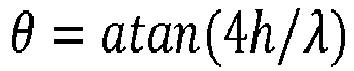
- La valeur de λ est choisie à partir de la longueur d'onde de la turbulence du fluide arrivant au bord d'attaque de l'aube.
- La
figure 2 illustre le résultat de l'application de ces formules sur des aubes 100, où l'on observe les dents 112 et les creux 114 du bord d'attaque 108 et les ondulations périodiques. Lafigure 3 représente schématiquement ces dents et creux. - Toutefois, la présence des dents 112 au bord d'attaque 108 réduit fortement le bilan mécanique des OGV, avec de fortes concentrations de contraintes dans les creux de dent.
- En effet sous effort aérodynamique la pale fléchit tangentiellement, ce qui induit un effet de cisaillement transverse d'une dent à l'autre. Ainsi plus les dents sont longues, plus le rayon des creux de dent est faible, et plus la contrainte dans les creux de dents sera élevée.
- Or, ce constat est inverse au gain acoustique escompté puisque ce dernier est maximisé pour des dents fines et longues.
- Il existe donc un besoin de solutions permettant de protéger les aubes ayant des profils en serration.
- Pour cela, l'invention propose une aube de stator comprenant :
- un pied d'aube,
- une tête d'aube,
- un bord d'attaque s'étendant entre le pied et la tête, le bord d'attaque ayant un profil en serration présentant une succession de dents et de creux ayant chacune une amplitude et une épaisseur,
- L'invention peut comprendre les caractéristiques suivantes, prises seules ou en combinaison :
- la série comprend au moins quatre dents et quatre creux,
- la série s'étend entre 20 et 50% de la longueur de l'aube,
- le profil en serration est de type sinusoïdal et dans laquelle, au niveau de la série, l'amplitude et/ou l'épaisseur des dents et des creux est combinée à une fonction linéaire, parabolique, sinusoidale ou exponentielle,
- le profil en serration s'exprime sous la forme suivante :
- Où c0 est la corde de référence, h l'amplitude et λ la longueur d'onde des ondulations et r le rayon
- au niveau de la série, l'amplitude et/ou l'épaisseur des dents et des creux est combinée à
une fonction linéaire de sorte que le profil s'exprime au niveau de ladite série :
ou
une fonction parabolique de sorte que le profil s'exprime au niveau de ladite série :
ou
une fonction sinusoïdale de sorte que le profil s'exprime au niveau de ladite série :
ou
une fonction exponentielle de sorte que le profil s'exprime au niveau de ladite série :
- l'aube est en matériau composite,
- l'amplitude du premier creux ou de la première dent à partir de la tête ou du pied d'aube n'est pas nulle,
- L'invention concerne aussi une couronne de redresseur comprenant une pluralité d'aubes telles que décrites précédemment, les aubes étant réparties circonférentiellement autour d'un moyeu.
- L'invention concerne aussi une turbomachine ou un banc d'essai comprenant une aube ou une couronne telle que décrite précédemment. Il s'agit d'une turbomachine ou un banc d'essai par exemple de type turbomachine partielle, cet ensemble étant par exemple un redresseur monoflux de la turbomachine partielle en constituant une veine qui correspondrait à une veine secondaire en considérant le cas d'une turbomachine complète.
- D'autres caractéristiques, buts et avantages de l'invention ressortiront de la description qui suit, qui est purement illustrative et non limitative, et qui doit être lue en regard des dessins annexés, sur lesquels :
- La
figure 1 représente un schéma illustrant les grandeurs définissant un profil en serration, - Les
figures 2 et3 illustrent une partie d'aube de stator avec un profil en serration et son agrandissement, - La
figure 4 illustre une partie d'aube de stator avec un profil en serration conforme à un mode de réalisation de l'invention, - La
figure 5 illustre une sinusoïde, - Les
figures 6 à 9 illustrent des sinusoïdes combinées à différentes fonctions dans le cadre de l'invention. - On se place dans le cadre d'une portion de turbomachine, typiquement une veine qui pourrait être équivalente à une veine secondaire d'une turbomachine double flux avec redresseur (OGV) disposé en sortie de soufflante. Il peut donc s'agir d'un cadre de banc d'essai, par exemple pour des redresseurs monoflux ou tout type de banc d'essai dans lequel une aube fixe est utilisée. Un tel banc d'essai est par exemple un moteur partiel permettant par exemple de valider des données sur des phénomènes représentatifs de ceux intervenant habituellement dans la veine secondaire d'un moteur complet.
- La
figure 4 illustre une partie d'aube 100 comprenant un pied d'aube 110 à une extrémité, qui est typiquement une extrémité radialement interne de l'aube 100. Le pied d'aube 110 s'attache à un moyeu 200, de révolution autour d'un axe longitudinal, qui correspond à un axe de rotation principale de la portion de turbomachine. Le moyeu 200 fait généralement partie du corps primaire d'une turbomachine double flux. L'aube 100 s'étend dans une direction radiale Y par rapport au moyeu 200 (chaque aube possède donc sa direction radiale Y propre).
A une autre extrémité, radialement externe, l'aube 100 est attachée à un carter 250 par une tête d'aube 115. - Pour former la veine V, une plateforme intérieure 220 peut être prévue radialement au-delà du moyeu 200, qui n'a pas de fonction aérodynamique.
- L'aube 100 a une forme profilée pour redresser le flux, avec notamment un intrados et un extrados. Le pied 110 d'aube 100 peut avoir une forme dans le prolongement de l'intrados et de l'extrados.
- L'aube 100 comprend un bord d'attaque 120 en serration, c'est-à-dire qu'il présente des ondulations, sous la forme d'une alternance de dents 122 et de creux 124, par exemple selon un motif sinusoïdal comme décrit en introduction.
- L'aube 100 peut être en métal ou en matériau composite (matrice de résine avec renforts, typiquement en carbone).
- Afin de protéger le profil serration, un objectif de l'invention est de soulager mécaniquement les dents et creux où les contraintes sont les plus importantes.
- Pour cela, comme illustré en
figure 4 , on définit une série 300 d'au moins trois dents 122 et trois creux 124 successifs, à partir du pied d'aube 110 et/ou de la tête d'aube 115. En d'autres termes, cette série 300 comprend les serrations les plus proches du bord de la veine V. Sur cette série, l'amplitude des dents 122 et des creux 124 va en diminuant en s'approchant du pied d'aube 110 ou de la tête d'aube 115. Alternativement ou complémentairement, il s'agit de l'épaisseur du bord d'attaque 120 qui va en augmentant en s'approchant du pied d'aube 110 ou de la tête d'aube 115. - Cette série 300 peut se retrouver au niveau de la tête de d'aube 115 et/ou du pied d'aube 110.
- L'amplitude est définie comme la distance entre le sommet (de la dent ou du creux) par rapport au profil droit. Il correspond donc au « h sin(2πr/λ) » de la formule donnée en introduction.
- L'épaisseur est définie au niveau du profil droit (c'est-à-dire pour une amplitude de dent ou de creux nulle). En effet, l'épaisseur de l'aube 100 est variable entre l'amont et l'aval de l'aube : elle est par exemple plus faible au niveau des sommets des dents 122 qu'au niveau des sommets des creux 124.
- Une telle aube 100 permet de répartir la charge en lissant la contrainte sur plusieurs serrations.
- Dans la suite de la demande, on ne parlera que de « diminution de l'amplitude », qui peut être remplacée par « augmentation de l'épaisseur ».
Pour assurer cette continuité, la diminution de l'amplitude peut être régie par des formules. - On rappelle qu'on se place dans le cadre d'une aube 100 dont le profil en serration est défini de la forme suivante :

- Où c0 est la corde de référence, h l'amplitude et λ la longueur d'onde des ondulations et r le rayon. Par le rayon, on entend le positionnement le long du bord d'attaque 120 (qui s'étend radialement à partir de l'axe longitudinal, d'où le terme de rayon). On suppose que r=0 signifie que l'on se trouve contre le bord de la veine V, soit au niveau de la tête d'aube 115 soit au niveau du pied d'aube 110.
On simplifie conceptuellement l'équation en considérant que λ est une constante fixée arbitrairement.
Ce profil sinusoïdal régulier Ps est illustré enfigure 5 . - Plusieurs modes de réalisations permettent de moduler les serrations dans la série 300.
- Dans un mode de réalisation illustré en
figure 6 , la diminution se fait par une fonction linéaire. Le profil PI sur la série 300 s'exprime alors sous la forme suivante :
- Dans un mode de réalisation illustré en
figure 7 , la diminution se fait par une fonction parabolique. Le profil Pp s'exprime alors sous la forme suivante :
- Dans un mode de réalisation illustré en
figure 8 , la diminution se fait par une fonction sinusoïdale. Le profil Pc s'exprime alors sous la forme suivante :
- Dans un mode de réalisation illustré en
figure 9 , la diminution se fait par une fonction exponentielle. Le profil Pe s'exprime alors sous la forme suivante :
- Toute fonction continue strictement décroissante en direction du pied 110 ou de la tête 115 d'aube convient en pratique.
- Préférablement, on évite que la première dent 122 ou le premier creux 124 ait une amplitude nulle, car cela ne fait que reporter la charge sur la dent ou le creux suivant. Pour cela, il suffit d'intégrer un léger offset, de type r-r0 dans les équations données ci-dessus.
- Dans un mode de réalisation, la série 300 comprend quatre, voire cinq creux et cinq dents successifs.
Dans un mode de réalisation, la série 300 s'étend entre 20 et 50% de la longueur de l'aube 100 dans la veine. - Il est possible de combiner les variations d'amplitude et d'épaisseur, afin de créer un profil d'aube 100 variable tridimensionnellement.
- Outre une turbomachine, cette aube 100 peut être montée dans le cadre d'un banc d'essai ou d'une turbomachine de test.

Claims (8)
- Aube (100) de stator comprenant :- un pied d'aube (110),- une tête d'aube (115),- un bord d'attaque (120) s'étendant entre le pied (110) et la tête (115), le bord d'attaque ayant un profil en serration présentant une succession de dents (122) et de creux (124) ayant chacune une amplitude et une épaisseur,caractérisée en ce qu'une série (300) d'au moins trois dents (122) et trois creux (124) consécutifs à partir du pied d'aube (110) et/ou de la tête d'aube (115) présentent une amplitude et/ou une épaisseur croissante.
- Aube (100) selon la revendication 1, dans laquelle la série (300) comprend au moins quatre dents et quatre creux ou s'étend entre 20 et 50% de la longueur de l'aube (100).
- Aube (100) selon l'une quelconque des revendications 1 à 2, dans laquelle le profil en serration est de type sinusoïdal et dans laquelle, au niveau de la série (300), l'amplitude et/ou l'épaisseur des dents et des creux est combinée à une fonction linéaire, parabolique, sinusoidale ou exponentielle.
- Aube (100) selon l'une quelconque des revendications 1 à 3, dans lequel le profil en serration s'exprime sous la forme suivante :

et dans laquelle, au niveau de la série (300), l'amplitude et/ou l'épaisseur des dents et des creux est combinée à
une fonction linéaire de sorte que le profil s'exprime au niveau de ladite série :
ou
une fonction parabolique de sorte que le profil s'exprime au niveau de ladite série :
ou
une fonction sinusoidale de sorte que le profil s'exprime au niveau de ladite série :
ou
une fonction exponentielle de sorte que le profil s'exprime au niveau de ladite série :
- Aube selon l'une quelconque des revendications 1 à 4, dans lequel l'aube (100) est en matériau composite.
- Aube selon l'une quelconque des revendications 1 à 5, dans laquelle l'amplitude du premier creux (124) ou de la première dent (122) à partir de la tête (110) ou du pied d'aube (115) n'est pas nulle.
- Couronne de redresseur comprenant une pluralité d'aubes selon l'une quelconque des revendications 1 à 6, les aubes (100) étant réparties circonférentiellement autour d'un moyeu (200).
- Turbomachine ou banc d'essai comprenant une aube selon l'une quelconque des revendications 1 à 6 ou une couronne selon la revendication 7.
Applications Claiming Priority (1)
| Application Number | Priority Date | Filing Date | Title |
|---|---|---|---|
| FR1760212A FR3073016B1 (fr) | 2017-10-30 | 2017-10-30 | Modulation des serrations en extremite d'aube |
Publications (2)
| Publication Number | Publication Date |
|---|---|
| EP3477057A1 true EP3477057A1 (fr) | 2019-05-01 |
| EP3477057B1 EP3477057B1 (fr) | 2022-02-09 |
Family
ID=61873377
Family Applications (1)
| Application Number | Title | Priority Date | Filing Date |
|---|---|---|---|
| EP18306419.5A Active EP3477057B1 (fr) | 2017-10-30 | 2018-10-30 | Modulation des serrations en extrémité d'aube |
Country Status (3)
| Country | Link |
|---|---|
| US (1) | US10941667B2 (fr) |
| EP (1) | EP3477057B1 (fr) |
| FR (1) | FR3073016B1 (fr) |
Cited By (2)
| Publication number | Priority date | Publication date | Assignee | Title |
|---|---|---|---|---|
| JP2022505328A (ja) * | 2018-10-18 | 2022-01-14 | サフラン・エアクラフト・エンジンズ | 航空機またはターボ機械のためのプロファイル構造 |
| CN119508280A (zh) * | 2024-10-17 | 2025-02-25 | 大连海事大学 | 一种带有局部非光滑减阻肋条表面的高负荷扩压叶栅结构及其设计方法 |
Families Citing this family (9)
| Publication number | Priority date | Publication date | Assignee | Title |
|---|---|---|---|---|
| CN109114019A (zh) * | 2017-06-23 | 2019-01-01 | 博格华纳公司 | 轴向风扇 |
| GB201809353D0 (en) * | 2018-06-07 | 2018-07-25 | Rolls Royce Plc | Aerofoil |
| FR3103231B1 (fr) * | 2019-11-19 | 2022-07-29 | Safran Aircraft Engines | Turbomachine à aubes ondulées |
| US12181151B2 (en) | 2021-07-29 | 2024-12-31 | General Electric Company | Mixer vanes having a waveform profile |
| FR3125797B1 (fr) * | 2021-07-29 | 2025-09-26 | Safran Aircraft Engines | Propulseur pour un aéronef |
| US11767790B2 (en) * | 2021-08-23 | 2023-09-26 | General Electric Company | Object direction mechanism for turbofan engine |
| FR3133646B1 (fr) * | 2022-03-16 | 2024-06-07 | Safran Aircraft Engines | Aube pour une turbomachine d’aéronef |
| EP4283135A1 (fr) * | 2022-05-24 | 2023-11-29 | ebm-papst Mulfingen GmbH & Co. KG | Dispositif de guidage et ventilateur doté d'un dispositif de guidage |
| US12292017B1 (en) | 2024-06-14 | 2025-05-06 | General Electric Company | Gas turbine engine with acoustic spacing of the fan blades and outlet guide vanes |
Citations (4)
| Publication number | Priority date | Publication date | Assignee | Title |
|---|---|---|---|---|
| EP1607573A1 (fr) * | 2004-06-02 | 2005-12-21 | Rolls-Royce Deutschland Ltd & Co KG | Aube de compresseur avec une sensibilité réduite de vibration |
| US20130164488A1 (en) * | 2011-12-22 | 2013-06-27 | General Electric Company | Airfoils for wake desensitization and method for fabricating same |
| FR3023329A1 (fr) * | 2014-07-03 | 2016-01-08 | Snecma | Stator ondule pour diminuer le bruit cree par l'interaction avec un rotor |
| EP3205826A1 (fr) * | 2016-02-10 | 2017-08-16 | General Electric Company | Ensemble de profil d'aube avec element en bord d'attaque |
Family Cites Families (6)
| Publication number | Priority date | Publication date | Assignee | Title |
|---|---|---|---|---|
| US2749473A (en) * | 1953-11-20 | 1956-06-05 | Rca Corp | Beam convergence system for tri-color kinescope |
| US3365126A (en) * | 1965-09-01 | 1968-01-23 | Gen Electric | Compressor blade |
| US5455103A (en) * | 1994-01-24 | 1995-10-03 | Monsanto Company | Rough-surfaced interlayer |
| US10443399B2 (en) * | 2016-07-22 | 2019-10-15 | General Electric Company | Turbine vane with coupon having corrugated surface(s) |
| US11156099B2 (en) * | 2017-03-28 | 2021-10-26 | General Electric Company | Turbine engine airfoil with a modified leading edge |
| FR3087483B1 (fr) * | 2018-10-18 | 2022-01-28 | Safran Aircraft Engines | Structure profilee pour aeronef ou turbomachine pour aeronef |
-
2017
- 2017-10-30 FR FR1760212A patent/FR3073016B1/fr not_active Expired - Fee Related
-
2018
- 2018-10-30 US US16/174,553 patent/US10941667B2/en active Active
- 2018-10-30 EP EP18306419.5A patent/EP3477057B1/fr active Active
Patent Citations (4)
| Publication number | Priority date | Publication date | Assignee | Title |
|---|---|---|---|---|
| EP1607573A1 (fr) * | 2004-06-02 | 2005-12-21 | Rolls-Royce Deutschland Ltd & Co KG | Aube de compresseur avec une sensibilité réduite de vibration |
| US20130164488A1 (en) * | 2011-12-22 | 2013-06-27 | General Electric Company | Airfoils for wake desensitization and method for fabricating same |
| FR3023329A1 (fr) * | 2014-07-03 | 2016-01-08 | Snecma | Stator ondule pour diminuer le bruit cree par l'interaction avec un rotor |
| EP3205826A1 (fr) * | 2016-02-10 | 2017-08-16 | General Electric Company | Ensemble de profil d'aube avec element en bord d'attaque |
Cited By (4)
| Publication number | Priority date | Publication date | Assignee | Title |
|---|---|---|---|---|
| JP2022505328A (ja) * | 2018-10-18 | 2022-01-14 | サフラン・エアクラフト・エンジンズ | 航空機またはターボ機械のためのプロファイル構造 |
| EP3867498B1 (fr) * | 2018-10-18 | 2023-04-19 | Safran Aircraft Engines | Structure profilee pour aeronef ou turbomachine |
| JP7463360B2 (ja) | 2018-10-18 | 2024-04-08 | サフラン・エアクラフト・エンジンズ | 航空機またはターボ機械のためのプロファイル構造 |
| CN119508280A (zh) * | 2024-10-17 | 2025-02-25 | 大连海事大学 | 一种带有局部非光滑减阻肋条表面的高负荷扩压叶栅结构及其设计方法 |
Also Published As
| Publication number | Publication date |
|---|---|
| US10941667B2 (en) | 2021-03-09 |
| FR3073016B1 (fr) | 2019-10-18 |
| EP3477057B1 (fr) | 2022-02-09 |
| US20190170003A1 (en) | 2019-06-06 |
| FR3073016A1 (fr) | 2019-05-03 |
Similar Documents
| Publication | Publication Date | Title |
|---|---|---|
| EP3477057B1 (fr) | Modulation des serrations en extrémité d'aube | |
| EP3676480B1 (fr) | Aube de redresseur de soufflante de turbomachine, ensemble de turbomachine comprenant une telle aube et turbomachine equipee de ladite aube ou dudit ensemble | |
| EP3752718B1 (fr) | Turbomachine à soufflante avant | |
| EP3752729B1 (fr) | Structure profilée d'écoulement d'air et turbomachine pour aéronef | |
| FR3023329B1 (fr) | Stator ondule pour diminuer le bruit cree par l'interaction avec un rotor | |
| FR3125797A1 (fr) | Propulseur pour un aéronef | |
| WO2020079335A1 (fr) | Structure profilee pour aeronef ou turbomachine | |
| FR3073017A1 (fr) | Membrane avec actionneurs pour bord d'attaque d'aube | |
| FR3073018A1 (fr) | Capot rapporte en profil de serration pour aube | |
| FR3118792A1 (fr) | Module pour une turbomachine d’aeronef | |
| FR3072607A1 (fr) | Turbomachine comprenant un ensemble de redressement | |
| WO2023021258A1 (fr) | Pièce statorique d'une turbomachine comprenant une pale et une ailette définissant entre elles une surface décroissante d'amont en aval selon le sens d'écoulement des gaz | |
| FR3048228A1 (fr) | Moyeu d'helice a pales a calage variable avec variation radiale et axiale de dimensionnement | |
| FR3052494A1 (fr) | Etage redresseur a calage variable pour compresseur de turbomachine comportant un joint d'etancheite sur carter externe et/ou anneau interne | |
| FR3073019A1 (fr) | Chemin d'effort courbe dans une aube | |
| EP4569209B1 (fr) | Aube à calage variable de stator de turbomachine d'aéronef et turbomachine d'aéronef | |
| BE1032189B1 (fr) | Aube pour compresseur de turbomachine d'aeronef, compresseur, turbomachine | |
| BE1032707A1 (fr) | Aube pour compresseur de turbomachine d'aeronef, compresseur, turbomachine | |
| BE1032191B1 (fr) | Ensemble de turbomachine et turbomachine | |
| EP3477052A1 (fr) | Profil non-axisymétrique de carter pour compresseur de turbomachine | |
| BE1024827B1 (fr) | Aube glaciophobe de compresseur de turbomachine axiale | |
| FR3155209A1 (fr) | Soufflante pour propulsion aéronautique | |
| WO2021181025A1 (fr) | Systeme de ventilation pour moteur | |
| FR3151628A1 (fr) | Soufflante pour propulsion aéronautique | |
| FR3155208A1 (fr) | Soufflante pour propulsion aéronautique |
Legal Events
| Date | Code | Title | Description |
|---|---|---|---|
| PUAI | Public reference made under article 153(3) epc to a published international application that has entered the european phase |
Free format text: ORIGINAL CODE: 0009012 |
|
| STAA | Information on the status of an ep patent application or granted ep patent |
Free format text: STATUS: REQUEST FOR EXAMINATION WAS MADE |
|
| 17P | Request for examination filed |
Effective date: 20181030 |
|
| AK | Designated contracting states |
Kind code of ref document: A1 Designated state(s): AL AT BE BG CH CY CZ DE DK EE ES FI FR GB GR HR HU IE IS IT LI LT LU LV MC MK MT NL NO PL PT RO RS SE SI SK SM TR |
|
| AX | Request for extension of the european patent |
Extension state: BA ME |
|
| GRAP | Despatch of communication of intention to grant a patent |
Free format text: ORIGINAL CODE: EPIDOSNIGR1 |
|
| STAA | Information on the status of an ep patent application or granted ep patent |
Free format text: STATUS: GRANT OF PATENT IS INTENDED |
|
| INTG | Intention to grant announced |
Effective date: 20211202 |
|
| GRAS | Grant fee paid |
Free format text: ORIGINAL CODE: EPIDOSNIGR3 |
|
| GRAA | (expected) grant |
Free format text: ORIGINAL CODE: 0009210 |
|
| STAA | Information on the status of an ep patent application or granted ep patent |
Free format text: STATUS: THE PATENT HAS BEEN GRANTED |
|
| AK | Designated contracting states |
Kind code of ref document: B1 Designated state(s): AL AT BE BG CH CY CZ DE DK EE ES FI FR GB GR HR HU IE IS IT LI LT LU LV MC MK MT NL NO PL PT RO RS SE SI SK SM TR |
|
| REG | Reference to a national code |
Ref country code: GB Ref legal event code: FG4D Free format text: NOT ENGLISH |
|
| REG | Reference to a national code |
Ref country code: CH Ref legal event code: EP Ref country code: AT Ref legal event code: REF Ref document number: 1467631 Country of ref document: AT Kind code of ref document: T Effective date: 20220215 |
|
| REG | Reference to a national code |
Ref country code: IE Ref legal event code: FG4D Free format text: LANGUAGE OF EP DOCUMENT: FRENCH |
|
| REG | Reference to a national code |
Ref country code: DE Ref legal event code: R096 Ref document number: 602018030545 Country of ref document: DE |
|
| REG | Reference to a national code |
Ref country code: LT Ref legal event code: MG9D |
|
| REG | Reference to a national code |
Ref country code: NL Ref legal event code: MP Effective date: 20220209 |
|
| REG | Reference to a national code |
Ref country code: AT Ref legal event code: MK05 Ref document number: 1467631 Country of ref document: AT Kind code of ref document: T Effective date: 20220209 |
|
| PG25 | Lapsed in a contracting state [announced via postgrant information from national office to epo] |
Ref country code: SE Free format text: LAPSE BECAUSE OF FAILURE TO SUBMIT A TRANSLATION OF THE DESCRIPTION OR TO PAY THE FEE WITHIN THE PRESCRIBED TIME-LIMIT Effective date: 20220209 Ref country code: RS Free format text: LAPSE BECAUSE OF FAILURE TO SUBMIT A TRANSLATION OF THE DESCRIPTION OR TO PAY THE FEE WITHIN THE PRESCRIBED TIME-LIMIT Effective date: 20220209 Ref country code: PT Free format text: LAPSE BECAUSE OF FAILURE TO SUBMIT A TRANSLATION OF THE DESCRIPTION OR TO PAY THE FEE WITHIN THE PRESCRIBED TIME-LIMIT Effective date: 20220609 Ref country code: NO Free format text: LAPSE BECAUSE OF FAILURE TO SUBMIT A TRANSLATION OF THE DESCRIPTION OR TO PAY THE FEE WITHIN THE PRESCRIBED TIME-LIMIT Effective date: 20220509 Ref country code: NL Free format text: LAPSE BECAUSE OF FAILURE TO SUBMIT A TRANSLATION OF THE DESCRIPTION OR TO PAY THE FEE WITHIN THE PRESCRIBED TIME-LIMIT Effective date: 20220209 Ref country code: LT Free format text: LAPSE BECAUSE OF FAILURE TO SUBMIT A TRANSLATION OF THE DESCRIPTION OR TO PAY THE FEE WITHIN THE PRESCRIBED TIME-LIMIT Effective date: 20220209 Ref country code: HR Free format text: LAPSE BECAUSE OF FAILURE TO SUBMIT A TRANSLATION OF THE DESCRIPTION OR TO PAY THE FEE WITHIN THE PRESCRIBED TIME-LIMIT Effective date: 20220209 Ref country code: ES Free format text: LAPSE BECAUSE OF FAILURE TO SUBMIT A TRANSLATION OF THE DESCRIPTION OR TO PAY THE FEE WITHIN THE PRESCRIBED TIME-LIMIT Effective date: 20220209 Ref country code: BG Free format text: LAPSE BECAUSE OF FAILURE TO SUBMIT A TRANSLATION OF THE DESCRIPTION OR TO PAY THE FEE WITHIN THE PRESCRIBED TIME-LIMIT Effective date: 20220509 |
|
| PG25 | Lapsed in a contracting state [announced via postgrant information from national office to epo] |
Ref country code: PL Free format text: LAPSE BECAUSE OF FAILURE TO SUBMIT A TRANSLATION OF THE DESCRIPTION OR TO PAY THE FEE WITHIN THE PRESCRIBED TIME-LIMIT Effective date: 20220209 Ref country code: LV Free format text: LAPSE BECAUSE OF FAILURE TO SUBMIT A TRANSLATION OF THE DESCRIPTION OR TO PAY THE FEE WITHIN THE PRESCRIBED TIME-LIMIT Effective date: 20220209 Ref country code: GR Free format text: LAPSE BECAUSE OF FAILURE TO SUBMIT A TRANSLATION OF THE DESCRIPTION OR TO PAY THE FEE WITHIN THE PRESCRIBED TIME-LIMIT Effective date: 20220510 Ref country code: FI Free format text: LAPSE BECAUSE OF FAILURE TO SUBMIT A TRANSLATION OF THE DESCRIPTION OR TO PAY THE FEE WITHIN THE PRESCRIBED TIME-LIMIT Effective date: 20220209 Ref country code: AT Free format text: LAPSE BECAUSE OF FAILURE TO SUBMIT A TRANSLATION OF THE DESCRIPTION OR TO PAY THE FEE WITHIN THE PRESCRIBED TIME-LIMIT Effective date: 20220209 |
|
| PG25 | Lapsed in a contracting state [announced via postgrant information from national office to epo] |
Ref country code: IS Free format text: LAPSE BECAUSE OF FAILURE TO SUBMIT A TRANSLATION OF THE DESCRIPTION OR TO PAY THE FEE WITHIN THE PRESCRIBED TIME-LIMIT Effective date: 20220609 |
|
| PG25 | Lapsed in a contracting state [announced via postgrant information from national office to epo] |
Ref country code: SM Free format text: LAPSE BECAUSE OF FAILURE TO SUBMIT A TRANSLATION OF THE DESCRIPTION OR TO PAY THE FEE WITHIN THE PRESCRIBED TIME-LIMIT Effective date: 20220209 Ref country code: SK Free format text: LAPSE BECAUSE OF FAILURE TO SUBMIT A TRANSLATION OF THE DESCRIPTION OR TO PAY THE FEE WITHIN THE PRESCRIBED TIME-LIMIT Effective date: 20220209 Ref country code: RO Free format text: LAPSE BECAUSE OF FAILURE TO SUBMIT A TRANSLATION OF THE DESCRIPTION OR TO PAY THE FEE WITHIN THE PRESCRIBED TIME-LIMIT Effective date: 20220209 Ref country code: EE Free format text: LAPSE BECAUSE OF FAILURE TO SUBMIT A TRANSLATION OF THE DESCRIPTION OR TO PAY THE FEE WITHIN THE PRESCRIBED TIME-LIMIT Effective date: 20220209 Ref country code: DK Free format text: LAPSE BECAUSE OF FAILURE TO SUBMIT A TRANSLATION OF THE DESCRIPTION OR TO PAY THE FEE WITHIN THE PRESCRIBED TIME-LIMIT Effective date: 20220209 Ref country code: CZ Free format text: LAPSE BECAUSE OF FAILURE TO SUBMIT A TRANSLATION OF THE DESCRIPTION OR TO PAY THE FEE WITHIN THE PRESCRIBED TIME-LIMIT Effective date: 20220209 |
|
| REG | Reference to a national code |
Ref country code: DE Ref legal event code: R097 Ref document number: 602018030545 Country of ref document: DE |
|
| PG25 | Lapsed in a contracting state [announced via postgrant information from national office to epo] |
Ref country code: AL Free format text: LAPSE BECAUSE OF FAILURE TO SUBMIT A TRANSLATION OF THE DESCRIPTION OR TO PAY THE FEE WITHIN THE PRESCRIBED TIME-LIMIT Effective date: 20220209 |
|
| PLBE | No opposition filed within time limit |
Free format text: ORIGINAL CODE: 0009261 |
|
| STAA | Information on the status of an ep patent application or granted ep patent |
Free format text: STATUS: NO OPPOSITION FILED WITHIN TIME LIMIT |
|
| 26N | No opposition filed |
Effective date: 20221110 |
|
| PG25 | Lapsed in a contracting state [announced via postgrant information from national office to epo] |
Ref country code: SI Free format text: LAPSE BECAUSE OF FAILURE TO SUBMIT A TRANSLATION OF THE DESCRIPTION OR TO PAY THE FEE WITHIN THE PRESCRIBED TIME-LIMIT Effective date: 20220209 |
|
| PG25 | Lapsed in a contracting state [announced via postgrant information from national office to epo] |
Ref country code: MC Free format text: LAPSE BECAUSE OF FAILURE TO SUBMIT A TRANSLATION OF THE DESCRIPTION OR TO PAY THE FEE WITHIN THE PRESCRIBED TIME-LIMIT Effective date: 20220209 |
|
| REG | Reference to a national code |
Ref country code: CH Ref legal event code: PL |
|
| REG | Reference to a national code |
Ref country code: BE Ref legal event code: MM Effective date: 20221031 |
|
| PG25 | Lapsed in a contracting state [announced via postgrant information from national office to epo] |
Ref country code: LU Free format text: LAPSE BECAUSE OF NON-PAYMENT OF DUE FEES Effective date: 20221030 |
|
| PG25 | Lapsed in a contracting state [announced via postgrant information from national office to epo] |
Ref country code: LI Free format text: LAPSE BECAUSE OF NON-PAYMENT OF DUE FEES Effective date: 20221031 Ref country code: IT Free format text: LAPSE BECAUSE OF FAILURE TO SUBMIT A TRANSLATION OF THE DESCRIPTION OR TO PAY THE FEE WITHIN THE PRESCRIBED TIME-LIMIT Effective date: 20220209 Ref country code: CH Free format text: LAPSE BECAUSE OF NON-PAYMENT OF DUE FEES Effective date: 20221031 |
|
| PG25 | Lapsed in a contracting state [announced via postgrant information from national office to epo] |
Ref country code: BE Free format text: LAPSE BECAUSE OF NON-PAYMENT OF DUE FEES Effective date: 20221031 |
|
| PG25 | Lapsed in a contracting state [announced via postgrant information from national office to epo] |
Ref country code: IE Free format text: LAPSE BECAUSE OF NON-PAYMENT OF DUE FEES Effective date: 20221030 |
|
| PG25 | Lapsed in a contracting state [announced via postgrant information from national office to epo] |
Ref country code: HU Free format text: LAPSE BECAUSE OF FAILURE TO SUBMIT A TRANSLATION OF THE DESCRIPTION OR TO PAY THE FEE WITHIN THE PRESCRIBED TIME-LIMIT; INVALID AB INITIO Effective date: 20181030 |
|
| PG25 | Lapsed in a contracting state [announced via postgrant information from national office to epo] |
Ref country code: CY Free format text: LAPSE BECAUSE OF FAILURE TO SUBMIT A TRANSLATION OF THE DESCRIPTION OR TO PAY THE FEE WITHIN THE PRESCRIBED TIME-LIMIT Effective date: 20220209 |
|
| PG25 | Lapsed in a contracting state [announced via postgrant information from national office to epo] |
Ref country code: MK Free format text: LAPSE BECAUSE OF FAILURE TO SUBMIT A TRANSLATION OF THE DESCRIPTION OR TO PAY THE FEE WITHIN THE PRESCRIBED TIME-LIMIT Effective date: 20220209 |
|
| PG25 | Lapsed in a contracting state [announced via postgrant information from national office to epo] |
Ref country code: MT Free format text: LAPSE BECAUSE OF FAILURE TO SUBMIT A TRANSLATION OF THE DESCRIPTION OR TO PAY THE FEE WITHIN THE PRESCRIBED TIME-LIMIT Effective date: 20220209 |
|
| PG25 | Lapsed in a contracting state [announced via postgrant information from national office to epo] |
Ref country code: TR Free format text: LAPSE BECAUSE OF FAILURE TO SUBMIT A TRANSLATION OF THE DESCRIPTION OR TO PAY THE FEE WITHIN THE PRESCRIBED TIME-LIMIT Effective date: 20220209 |
|
| PGFP | Annual fee paid to national office [announced via postgrant information from national office to epo] |
Ref country code: DE Payment date: 20251020 Year of fee payment: 8 |
|
| PGFP | Annual fee paid to national office [announced via postgrant information from national office to epo] |
Ref country code: GB Payment date: 20251029 Year of fee payment: 8 |
|
| PGFP | Annual fee paid to national office [announced via postgrant information from national office to epo] |
Ref country code: FR Payment date: 20251024 Year of fee payment: 8 |