EP3476786A1 - Packaging container - Google Patents
Packaging container Download PDFInfo
- Publication number
- EP3476786A1 EP3476786A1 EP18306350.2A EP18306350A EP3476786A1 EP 3476786 A1 EP3476786 A1 EP 3476786A1 EP 18306350 A EP18306350 A EP 18306350A EP 3476786 A1 EP3476786 A1 EP 3476786A1
- Authority
- EP
- European Patent Office
- Prior art keywords
- packaging container
- guide member
- cable
- tube section
- telescopically
- Prior art date
- Legal status (The legal status is an assumption and is not a legal conclusion. Google has not performed a legal analysis and makes no representation as to the accuracy of the status listed.)
- Withdrawn
Links
Images




Classifications
-
- B—PERFORMING OPERATIONS; TRANSPORTING
- B65—CONVEYING; PACKING; STORING; HANDLING THIN OR FILAMENTARY MATERIAL
- B65D—CONTAINERS FOR STORAGE OR TRANSPORT OF ARTICLES OR MATERIALS, e.g. BAGS, BARRELS, BOTTLES, BOXES, CANS, CARTONS, CRATES, DRUMS, JARS, TANKS, HOPPERS, FORWARDING CONTAINERS; ACCESSORIES, CLOSURES, OR FITTINGS THEREFOR; PACKAGING ELEMENTS; PACKAGES
- B65D85/00—Containers, packaging elements or packages, specially adapted for particular articles or materials
- B65D85/02—Containers, packaging elements or packages, specially adapted for particular articles or materials for annular articles
- B65D85/04—Containers, packaging elements or packages, specially adapted for particular articles or materials for annular articles for coils of wire, rope or hose
-
- B—PERFORMING OPERATIONS; TRANSPORTING
- B65—CONVEYING; PACKING; STORING; HANDLING THIN OR FILAMENTARY MATERIAL
- B65H—HANDLING THIN OR FILAMENTARY MATERIAL, e.g. SHEETS, WEBS, CABLES
- B65H49/00—Unwinding or paying-out filamentary material; Supporting, storing or transporting packages from which filamentary material is to be withdrawn or paid-out
- B65H49/02—Methods or apparatus in which packages do not rotate
- B65H49/04—Package-supporting devices
- B65H49/06—Package-supporting devices for a single operative package
- B65H49/08—Package-supporting devices for a single operative package enclosing the package
-
- B—PERFORMING OPERATIONS; TRANSPORTING
- B65—CONVEYING; PACKING; STORING; HANDLING THIN OR FILAMENTARY MATERIAL
- B65H—HANDLING THIN OR FILAMENTARY MATERIAL, e.g. SHEETS, WEBS, CABLES
- B65H57/00—Guides for filamentary materials; Supports therefor
- B65H57/18—Guides for filamentary materials; Supports therefor mounted to facilitate unwinding of material from packages
-
- B—PERFORMING OPERATIONS; TRANSPORTING
- B65—CONVEYING; PACKING; STORING; HANDLING THIN OR FILAMENTARY MATERIAL
- B65H—HANDLING THIN OR FILAMENTARY MATERIAL, e.g. SHEETS, WEBS, CABLES
- B65H2701/00—Handled material; Storage means
- B65H2701/30—Handled filamentary material
- B65H2701/32—Optical fibres or optical cables
-
- B—PERFORMING OPERATIONS; TRANSPORTING
- B65—CONVEYING; PACKING; STORING; HANDLING THIN OR FILAMENTARY MATERIAL
- B65H—HANDLING THIN OR FILAMENTARY MATERIAL, e.g. SHEETS, WEBS, CABLES
- B65H2701/00—Handled material; Storage means
- B65H2701/30—Handled filamentary material
- B65H2701/34—Handled filamentary material electric cords or electric power cables
-
- B—PERFORMING OPERATIONS; TRANSPORTING
- B65—CONVEYING; PACKING; STORING; HANDLING THIN OR FILAMENTARY MATERIAL
- B65H—HANDLING THIN OR FILAMENTARY MATERIAL, e.g. SHEETS, WEBS, CABLES
- B65H2701/00—Handled material; Storage means
- B65H2701/30—Handled filamentary material
- B65H2701/36—Wires
Definitions
- the present invention relates to a packaging container, and more specifically to a packaging container for optical fibers or cables.
- Optical fibers are fragile due to their very small diameter, of the order of a few hundred microns, and their structure. A number of fibers are assembled to form a cable or wire, which inherits the fragile and soft nature of the fibers. The cables therefore need to be handled with special precautions especially during packaging, transportation and unpackaging.
- Soft cables are often packed into container arrangement by coiling the cable inside the container. To then use the cable, the cable is withdrawn from the packaging container, either manually, semi-automatically or automatically. During this unpackaging of the cable there is a risk that the cable can form a knot or fold over on itself or in any other way cause tangling of the cables. This may cause mechanical and/or optical damages to the cable.
- cable jetting is a method of blowing a cable through a duct while simultaneously pushing the cable into the duct. This may be achieved by injecting compressed air at the duct inlet, which then flows through the duct and along the cable at high speed. An additional pushing force is applied to the cable by a jetting equipment.
- the present invention preferably seeks to mitigate, alleviate or eliminate one or more of the above-identified deficiencies in the art and disadvantages singly or in any combination and solves at least the above mentioned problems by providing an improved packaging container.
- a packaging container for storage of a cable comprises a housing and a guide member, wherein the guide member comprises at least one telescopically arranged tube section for preventing tangling of cables during storage and unpacking of the cable.
- the guide member may be configured to be arranged in a telescopically retracted position and a telescopically extended position. Having a telescopic guide member has the benefit that the height of the packaging container can be significantly reduced. Having a packaging container with a low height is important since it is more cost efficient to have smaller containers during transportation and storage.
- the guide member may comprise a level mark to facilitate the arrangement of the guide member in its telescopically extended position. This makes uncoiling of the cable very user-friendly.
- the height of the guide member is greater than the height of the housing.
- the height of the guide member may be equal to or smaller than the height of the housing.
- the guide member may comprise one first tube section being fixedly arranged in the housing and the at least one telescopically arranged tube section being a second tube section.
- the second tube section has a slightly smaller diameter than the first tube section so that it is slidably arranged within the first tube section.
- the first tube section has a slightly smaller diameter than the second tube section so that it is slidably arranged within the second tube section.
- the height of the first and the second tube sections are the same. In an alternative embodiment the height of the first and the second tube sections are different.
- a method for packaging a cable into a packaging container comprises the steps of providing a packaging container according to the first aspect, coiling the cable around the guide member of the packaging container. If the guide member is in a telescopically extended position, the method further comprises arranging the guide member in a telescopically retracted position. The method further comprises closing the packaging container.
- a method for uncoiling a cable being arranged in a packaging container comprises the steps of opening the packaging container, arranging the guide member in a telescopically extended position, and uncoiling the cable.
- a housing 10 comprises a bottom side 12 arranged to be placed on a surface such as a floor, table or the ground.
- the bottom side 12 is thus substantially flat.
- the housing 10 may further comprise sidewalls 14 which extend in a longitudinal direction from the bottom side 12.
- the sidewalls 14 may have a height H1.
- the housing 10 is in the form of a cylinder having straight walls
- the embodiment shown in Fig. 1b has a housing 10 in the form of a tapered cylinder. It should be appreciated that the housing 10 could have other shapes than those illustrated in these figures.
- the housing may further comprise a removable top portion 16 that covers and protects the interior of the housing 10.
- the top portion 16 comprises locking means 18, such as locking cylinder or the like, in order to prevent unauthorized persons to open the packaging container 100.
- the packaging container 100 is constructed to store and protect a cable C, as shown in Fig. 3 .
- the cable may for example be a cable comprising optical fibers.
- the optical cable may be mainly composed of a plurality of optical fibers surrounded by a protective sheath.
- the cable or wire may also be made of any other kind of soft material that is sensitive and prone to tangling.
- the housing 10 is substantially cylindrical in shape.
- the housing 10 is preferably constructed by a material that is able to protect the cable during shipping. In some embodiments it is preferred if the material of the housing 10 is such that the packaging container 100 can be used indoors and/or outdoors. Additionally, or alternatively, it is beneficial if the material is a recyclable and environmentally friendly material.
- the housing 10 may for example be constructed by metal, a plastic material and/or cardboard.
- Fig. 2 shows an embodiment of the packaging container 100 where the removable top portion 16 is removed.
- the packaging container 100 comprises a guide member 20 that prevents the cable from forming a knot or fold over on itself or in any other way causes tangling of the cable that might cause mechanical and/or optical damages to the cable.
- the guide member is a telescopic guide member 20 comprising at least a first tube section 22 and a second tube section 24.
- the tube sections 22, 24 may be of any suitable shape, such as an octagon, pentagon, hexagon or similar. In a preferred embodiment the tube sections 22, 24 cylindrical in shape. At least one of the tube sections 22, 24 is telescopically arranged as will be described more with reference to Fig. 4a .
- the guide member 20 may comprise more than two tube sections depending on the desired height and configuration of the guide member 20.
- the packaging container 100 and the guide member 20 are preferably sold as one unit.
- the guide member 20 shall not only be seen as an accessory to be used only during uncoiling of the cable but as a stationary part of the packaging container 100.
- the packaging container 100 and the guide member 20 may be constructed as a single unit, or being constructed as separate units being fixedly arranged to each other. Having a guide member 20 arranged in the packaging container 100 as one of its components instead of being an accessory has several benefits, for example it allows for a simple and cheap solution since there is thus no need for the installer to purchase any additional accessories. Due to the minimized construction of the container 100 it is also very environmentally friendly.
- Fig. 3 illustrates a top view of the packaging container 100.
- the cross sectional shape of the guide member 20 may be cylindrical or circular.
- the cylindrical or circular cross sectional shape is adapted for coiling the cable C around its axis.
- the guide member 20 can for that purpose be seen as a coil.
- the guide member 20 is preferably arranged in the center portion of the housing 10.
- the guide member 20 may be constructed from any suitable material. It may for example be constructed from a polymer material, such as plastics or the like, that allows for a cheap and easy handling and manufacturing. In a preferred embodiment the guide member 20 is constructed from a recyclable material.
- Fig. 4a illustrates a situation where the guide member 20 is in between a first position, (as shown in Fig. 2 ) and a second position (as shown in Fig. 4b ).
- the first position can be seen as a telescopically retracted position, where the majority of the second tube section 24 is arranged inside the first tube section 22.
- the second position can be seen as a telescopically extended position where the majority of the second tube section 24 is pulled out to extend out from the first tube section 22.
- the movement, as seen in Fig. 4a of the guide member from the first to the second position is performed by manually pulling the second tube section 24 in a direction upwards, i.e. in a direction away from the bottom side 12.
- the movement of moving the guide member 20 from the second position to the first position is performed manually by pushing the second tube section 24 down towards the first tube section 22.
- the second position is instead seen as a telescopically extended position where the majority of the second tube section 24 is pulled up and around the first tube section 22. Hence, in the extended position the first tube section 22 is arranged inside of the second tube section 24.
- One of the tube sections 22, 24 are fixated at the bottom of the housing 10, whereas the other tube section 22, 24 is telescopically arranged either inside or outside of the fixated tube section 22, 24.
- the first tube section 22 is fixedly arranged in the housing 10 of the container 100, and the second tube section 24 is telescopically arranged.
- the second tube section 24 may be arranged either as the inner tube section or as the outer tube section.
- Fig. 2 and 4b illustrates the height of the guide member 20 when being arranged in its retracted and extracted position.
- the height H2 of the guide member 20, in a telescopically retracted position is equal to or less than the height H1 of the housing 10.
- the height H3 of the guide member 20 is larger than the height H1 of the housing 10.
- the guide member 20 is arranged in the first, retracted, position during storage and transportation where it is important to have a low height of the packaging container 100.
- the guide member 20 is arranged in the second, extended, position during unpacking and uncoiling of the cable C arranged inside the container 100 as illustratively shown in Fig. 4c . Having a telescopic guide member 20 thus has the benefit that the height of the packaging container 100 can be significantly reduced. Having a packaging container 100 with a low height is important since it is more cost efficient to have smaller containers 100 during transportation and storage.
- the first tube section 22 is provided with at least one open end in order to receive the second tube section 24.
- the second tube section 24 has a slightly smaller diameter than the first tube section 22, so that it is slidably arranged within the first tube section 22.
- the first tube section 22 is thus arranged at least partly outside of the second tube section 22 and the second tube section 24 is arranged at least partly on the inside of the first tube section 22.
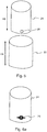
- Fig. 5 illustrates the tube sections 22, 24 in a dissembled state.
- the first tube section 22 has the height H4 and the second tube section 22 has a height H5.
- the height H4, H5 of the first and second tube sections 22, 24 are the same.
- the height H4, H5 of the first and second tube sections 22, 24 are different from each other.
- the guide member 20 may be held in the telescopically extended position in different ways.
- the tube sections 22, 24 are held in an extended position by a friction arrangement 28.
- the friction arrangement 28 may be arranged at the second tube section 24, preferably at the lower part of the second tube section 24. In an alternative embodiment the friction arrangement 28 is arranged at the upper part of the first tube section 22.
- the friction arrangement 28 may for example be a rubber pad or a felt pad that is attached to the tube section 22, 24 for example using adhesive.
- the friction arrangement 28 is constructed such that it, when arranged on the tube section 22, 24, increases the friction between the two tubes in order to create a friction lock.
- one of the tube sections 22, 24 are slightly tapered compared to the other tube section in order to create a friction lock. Additionally, or alternatively, one of the tube sections 22, 24 is arranged with a fitting that seals the two tube sections together in an extended position. In an alternative embodiment the two tube sections 22, 24 are held together in an extended position by mechanical locking means such as a latch.
- Fig. 6a illustrates a guide member 20 having a level mark 26.
- the level mark is here illustrated as a plimsoll line or a load line.
- any type of marking could be used.
- the second tube section 24 is provided with a level mark.
- the first tube section 22 is provided with a level mark.
- the level mark 26 is provided in order for the person unpacking the cables to know in what position the guide member 20 should be arranged.
- the level mark 26 thus illustrates how to level the second tube section 24 in relation to the first tube sections 22.
- Fig. 6b illustrates three different positions of the tube sections and where the correct arrangement of the second tube section 24 in relation to the first tube section 22 is shown in the upper part in the figure.
- the telescopic guide member 20 is arranged in its extended position when the cable is to be unpacked, for example using high speed cable jetting.
- the guide member 20 will prevent the cable from accidentally passing over the central area of the package container 100 during unpacking using for example high speed jetting.
- the packaging container 100 eliminates this problem by providing the telescopic guide member 20 that prevents the cable from tangling both during transportation (when arranged in a retracted position) and during unpacking (when arranged in an extended position).
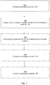
- a method 700 for packing a cable C into a packing container 100 is provided in Fig. 7 , where in a first step 710 a packaging container 100 is provided.
- a next step 720 the user coils the cable C around the guide member 20 of the container, during this step the guide member 20 may be arranged either in the retracted or extended position.
- the user arranges 730 the guide member 20 in a retracted position if the guide member 20 was in an extended position and closes 740 the container 100 using a top portion 16.
- the container 100 is locked using locking means 18, thus preventing unauthorized persons to open the container 100.
- a method 800 for unpacking a cable C being arranged in the packaging container 100 is provided in Fig. 8 . If locking means 18 was used, this is unlocked 810 and the removable top portion 16 is removed 820. The user arranges 830 the guide member 20 in its extended position by pulling up the second tube section 24. The user may now unpack and uncoil 840 the cable C without the risk of untangling.
- the packaging container 100 described herein allows for higher speed during cable jetting without jeopardizing the blowing operation. The cable can thus be uncoiled from the packaging in a more efficient manner.
- blowing equipment is positioned higher than the packaging container during jetting. In normal jetting operations the blowing equipment is typically arranged at a higher position than packaging container 100.
Landscapes
- Engineering & Computer Science (AREA)
- Mechanical Engineering (AREA)
- Packaging Of Annular Or Rod-Shaped Articles, Wearing Apparel, Cassettes, Or The Like (AREA)
Abstract
Description
- The present invention relates to a packaging container, and more specifically to a packaging container for optical fibers or cables.
- Optical fibers are fragile due to their very small diameter, of the order of a few hundred microns, and their structure. A number of fibers are assembled to form a cable or wire, which inherits the fragile and soft nature of the fibers. The cables therefore need to be handled with special precautions especially during packaging, transportation and unpackaging.
- Soft cables are often packed into container arrangement by coiling the cable inside the container. To then use the cable, the cable is withdrawn from the packaging container, either manually, semi-automatically or automatically. During this unpackaging of the cable there is a risk that the cable can form a knot or fold over on itself or in any other way cause tangling of the cables. This may cause mechanical and/or optical damages to the cable.
- There are many automatic or semi-automatic processes that unpack and uncoil cables from their packaging container. One such process is cable jetting, which is a method of blowing a cable through a duct while simultaneously pushing the cable into the duct. This may be achieved by injecting compressed air at the duct inlet, which then flows through the duct and along the cable at high speed. An additional pushing force is applied to the cable by a jetting equipment.
- There is therefore a need for a solution that eliminates or at least reduces the risk of cable tangling when unpacking and uncoiling the cable. More specifically, there is a need for a solution that allows safe and tangle free uncoiling of the cable from the packaging container when using automatic or semi-automatic processes.
- Accordingly, the present invention preferably seeks to mitigate, alleviate or eliminate one or more of the above-identified deficiencies in the art and disadvantages singly or in any combination and solves at least the above mentioned problems by providing an improved packaging container.
- In a first aspect, a packaging container for storage of a cable is provided. The container comprises a housing and a guide member, wherein the guide member comprises at least one telescopically arranged tube section for preventing tangling of cables during storage and unpacking of the cable. Having such a packaging container is a simple and cheap solution since there is thus no need for the installer to purchase any additional accessories in order to unpack the cable. Due to the minimized construction of the container it is also very environmentally friendly.
- The guide member may be configured to be arranged in a telescopically retracted position and a telescopically extended position. Having a telescopic guide member has the benefit that the height of the packaging container can be significantly reduced. Having a packaging container with a low height is important since it is more cost efficient to have smaller containers during transportation and storage.
- The guide member may comprise a level mark to facilitate the arrangement of the guide member in its telescopically extended position. This makes uncoiling of the cable very user-friendly.
- In one embodiment when the guide member is arranged in a telescopically extended position the height of the guide member is greater than the height of the housing. When the guide member is arranged in a telescopically retracted position, the height of the guide member may be equal to or smaller than the height of the housing.
- The guide member may comprise one first tube section being fixedly arranged in the housing and the at least one telescopically arranged tube section being a second tube section.
- In one embodiment the second tube section has a slightly smaller diameter than the first tube section so that it is slidably arranged within the first tube section. In an alternative embodiment, the first tube section has a slightly smaller diameter than the second tube section so that it is slidably arranged within the second tube section.
- In one embodiment the height of the first and the second tube sections are the same. In an alternative embodiment the height of the first and the second tube sections are different.
- In a second aspect, a method for packaging a cable into a packaging container is provided. The method comprises the steps of providing a packaging container according to the first aspect, coiling the cable around the guide member of the packaging container. If the guide member is in a telescopically extended position, the method further comprises arranging the guide member in a telescopically retracted position. The method further comprises closing the packaging container.
- In a third aspect, a method for uncoiling a cable being arranged in a packaging container according the first aspect. The method comprises the steps of opening the packaging container, arranging the guide member in a telescopically extended position, and uncoiling the cable.
- These and other aspects, features and advantages of which the invention is capable of will be apparent and elucidated from the following description of embodiments of the present invention, reference being made to the accompanying drawings, in which
-
Fig. 1a is an isometric view of a packaging container according to an embodiment; -
Fig. 1b is an isometric view of a packaging container according to an embodiment; -
Fig. 2 is an isometric inside view of a packaging container having a guide member being in a first position according to an embodiment; -
Fig. 3 is a top view of a packaging container according to an embodiment; -
Fig. 4a is an isometric inside view of a packaging container having a guide member being between a first and a second position according to an embodiment; -
Fig. 4b is an isometric inside view of a packaging container having a guide member being in a second position according to an embodiment; -
Fig. 4c is an isometric inside view of a packaging container having a guide member being in a second position according to an embodiment; -
Fig. 5 is an isometric view of a tube sections of a guide member being according to an embodiment; -
Fig. 6a is an isometric view of a tube section of a guide member according to an embodiment; -
Fig. 6b is a side view illustrating a part of a guide member according to an embodiment; -
Fig. 7 is a block scheme of a method for packaging a cable into a packaging container according to an embodiment; and -
Fig. 8 is a block scheme of a method for uncoiling a cable being arranged in a packaging container according to an embodiment. - Embodiments of a
packaging container 100 are shown inFigs. 1a-b . Ahousing 10 comprises abottom side 12 arranged to be placed on a surface such as a floor, table or the ground. Thebottom side 12 is thus substantially flat. Thehousing 10 may further comprise sidewalls 14 which extend in a longitudinal direction from thebottom side 12. The sidewalls 14 may have a height H1. InFig. 1a thehousing 10 is in the form of a cylinder having straight walls, whereas the embodiment shown inFig. 1b has ahousing 10 in the form of a tapered cylinder. It should be appreciated that thehousing 10 could have other shapes than those illustrated in these figures. - The housing may further comprise a removable
top portion 16 that covers and protects the interior of thehousing 10. In some embodiments, as shown inFig. 1b , thetop portion 16 comprises locking means 18, such as locking cylinder or the like, in order to prevent unauthorized persons to open thepackaging container 100. - The
packaging container 100 is constructed to store and protect a cable C, as shown inFig. 3 . The cable may for example be a cable comprising optical fibers. The optical cable may be mainly composed of a plurality of optical fibers surrounded by a protective sheath. The cable or wire may also be made of any other kind of soft material that is sensitive and prone to tangling. - In the embodiments shown in
Figs. 1a-b thehousing 10 is substantially cylindrical in shape. Thehousing 10 is preferably constructed by a material that is able to protect the cable during shipping. In some embodiments it is preferred if the material of thehousing 10 is such that thepackaging container 100 can be used indoors and/or outdoors. Additionally, or alternatively, it is beneficial if the material is a recyclable and environmentally friendly material. Thehousing 10 may for example be constructed by metal, a plastic material and/or cardboard. -
Fig. 2 shows an embodiment of thepackaging container 100 where the removabletop portion 16 is removed. Thepackaging container 100 comprises aguide member 20 that prevents the cable from forming a knot or fold over on itself or in any other way causes tangling of the cable that might cause mechanical and/or optical damages to the cable. The guide member is atelescopic guide member 20 comprising at least afirst tube section 22 and asecond tube section 24. Thetube sections tube sections tube sections Fig. 4a . Although not shown in the figures, theguide member 20 may comprise more than two tube sections depending on the desired height and configuration of theguide member 20. - The
packaging container 100 and theguide member 20 are preferably sold as one unit. Hence, theguide member 20 shall not only be seen as an accessory to be used only during uncoiling of the cable but as a stationary part of thepackaging container 100. Thepackaging container 100 and theguide member 20 may be constructed as a single unit, or being constructed as separate units being fixedly arranged to each other. Having aguide member 20 arranged in thepackaging container 100 as one of its components instead of being an accessory has several benefits, for example it allows for a simple and cheap solution since there is thus no need for the installer to purchase any additional accessories. Due to the minimized construction of thecontainer 100 it is also very environmentally friendly. -
Fig. 3 illustrates a top view of thepackaging container 100. The cross sectional shape of theguide member 20 may be cylindrical or circular. The cylindrical or circular cross sectional shape is adapted for coiling the cable C around its axis. Theguide member 20 can for that purpose be seen as a coil. Theguide member 20 is preferably arranged in the center portion of thehousing 10. - The
guide member 20 may be constructed from any suitable material. It may for example be constructed from a polymer material, such as plastics or the like, that allows for a cheap and easy handling and manufacturing. In a preferred embodiment theguide member 20 is constructed from a recyclable material. -
Fig. 4a illustrates a situation where theguide member 20 is in between a first position, (as shown inFig. 2 ) and a second position (as shown inFig. 4b ). The first position can be seen as a telescopically retracted position, where the majority of thesecond tube section 24 is arranged inside thefirst tube section 22. The second position can be seen as a telescopically extended position where the majority of thesecond tube section 24 is pulled out to extend out from thefirst tube section 22. The movement, as seen inFig. 4a , of the guide member from the first to the second position is performed by manually pulling thesecond tube section 24 in a direction upwards, i.e. in a direction away from thebottom side 12. The movement of moving theguide member 20 from the second position to the first position is performed manually by pushing thesecond tube section 24 down towards thefirst tube section 22. - In an alternative embodiment, the second position is instead seen as a telescopically extended position where the majority of the
second tube section 24 is pulled up and around thefirst tube section 22. Hence, in the extended position thefirst tube section 22 is arranged inside of thesecond tube section 24. - One of the
tube sections housing 10, whereas theother tube section fixated tube section first tube section 22 is fixedly arranged in thehousing 10 of thecontainer 100, and thesecond tube section 24 is telescopically arranged. Thesecond tube section 24 may be arranged either as the inner tube section or as the outer tube section. -
Fig. 2 and4b illustrates the height of theguide member 20 when being arranged in its retracted and extracted position. The height H2 of theguide member 20, in a telescopically retracted position, is equal to or less than the height H1 of thehousing 10. When theguide member 20 is arranged in the telescopically extended position, the height H3 of theguide member 20 is larger than the height H1 of thehousing 10. - The
guide member 20 is arranged in the first, retracted, position during storage and transportation where it is important to have a low height of thepackaging container 100. Theguide member 20 is arranged in the second, extended, position during unpacking and uncoiling of the cable C arranged inside thecontainer 100 as illustratively shown inFig. 4c . Having atelescopic guide member 20 thus has the benefit that the height of thepackaging container 100 can be significantly reduced. Having apackaging container 100 with a low height is important since it is more cost efficient to havesmaller containers 100 during transportation and storage. - In one embodiment, the
first tube section 22 is provided with at least one open end in order to receive thesecond tube section 24. Thesecond tube section 24 has a slightly smaller diameter than thefirst tube section 22, so that it is slidably arranged within thefirst tube section 22. Thefirst tube section 22 is thus arranged at least partly outside of thesecond tube section 22 and thesecond tube section 24 is arranged at least partly on the inside of thefirst tube section 22. -
Fig. 5 illustrates thetube sections first tube section 22 has the height H4 and thesecond tube section 22 has a height H5. In one embodiment the height H4, H5 of the first andsecond tube sections second tube sections - The
guide member 20 may be held in the telescopically extended position in different ways. In the embodiment shown inFig. 5 , thetube sections friction arrangement 28. Thefriction arrangement 28 may be arranged at thesecond tube section 24, preferably at the lower part of thesecond tube section 24. In an alternative embodiment thefriction arrangement 28 is arranged at the upper part of thefirst tube section 22. - The
friction arrangement 28 may for example be a rubber pad or a felt pad that is attached to thetube section friction arrangement 28 is constructed such that it, when arranged on thetube section - In one embodiment one of the
tube sections tube sections tube sections -
Fig. 6a illustrates aguide member 20 having alevel mark 26. The level mark is here illustrated as a plimsoll line or a load line. However, as should be appreciated by a person skilled in the art, any type of marking could be used. In one embodiment, as shown inFig. 6a , thesecond tube section 24 is provided with a level mark. In an alternative embodiment, thefirst tube section 22 is provided with a level mark. - The
level mark 26 is provided in order for the person unpacking the cables to know in what position theguide member 20 should be arranged. Thelevel mark 26 thus illustrates how to level thesecond tube section 24 in relation to thefirst tube sections 22.Fig. 6b , illustrates three different positions of the tube sections and where the correct arrangement of thesecond tube section 24 in relation to thefirst tube section 22 is shown in the upper part in the figure. - The
telescopic guide member 20 is arranged in its extended position when the cable is to be unpacked, for example using high speed cable jetting. The fact that the guide member, in an extended position, has a height H3 higher than the height of the housing H1 decreases the risk of cable tangling. Theguide member 20 will prevent the cable from accidentally passing over the central area of thepackage container 100 during unpacking using for example high speed jetting. - Studies have shown that the main cause of cable tangling during uncoiling in prior art systems is that the cable has moved inside the packaging container during transport. The cable may for example slide down through an underlying cable layer inside the packaging. In this case there is there a high risk that the cable will grab and lift up an overlying cable layer when jetting at high speeds, which immediately will cause tangling of the cable. The
packaging container 100 herein eliminates this problem by providing thetelescopic guide member 20 that prevents the cable from tangling both during transportation (when arranged in a retracted position) and during unpacking (when arranged in an extended position). - A method 700 for packing a cable C into a
packing container 100 is provided inFig. 7 , where in a first step 710 apackaging container 100 is provided. In anext step 720 the user coils the cable C around theguide member 20 of the container, during this step theguide member 20 may be arranged either in the retracted or extended position. Once the whole cable C is arranged inside the packaging container the user arranges 730 theguide member 20 in a retracted position if theguide member 20 was in an extended position and closes 740 thecontainer 100 using atop portion 16. In an optionaladditional step 750 thecontainer 100 is locked using locking means 18, thus preventing unauthorized persons to open thecontainer 100. - A method 800 for unpacking a cable C being arranged in the
packaging container 100 is provided inFig. 8 . If locking means 18 was used, this is unlocked 810 and the removabletop portion 16 is removed 820. The user arranges 830 theguide member 20 in its extended position by pulling up thesecond tube section 24. The user may now unpack and uncoil 840 the cable C without the risk of untangling. Thepackaging container 100 described herein allows for higher speed during cable jetting without jeopardizing the blowing operation. The cable can thus be uncoiled from the packaging in a more efficient manner. - Since there is no radius limiter at the top of the telescopic fiber guide, it is beneficial if the blowing equipment is positioned higher than the packaging container during jetting. In normal jetting operations the blowing equipment is typically arranged at a higher position than packaging
container 100. - In the claims, the term "comprises/comprising" does not exclude the presence of other elements or steps. Additionally, although individual features may be included in different claims, these may possibly advantageously be combined, and the inclusion in different claims does not imply that a combination of features is not feasible and/or advantageous. In addition, singular references do not exclude a plurality. The terms "a", "an", "first", "second" etc do not preclude a plurality. Reference signs in the claims are provided merely as a clarifying example and shall not be construed as limiting the scope of the claims in any way.
Claims (15)
- A packaging container (100) for storage of a cable (C), wherein the container comprises a housing (10) and a guide member (20), wherein the guide member (20) comprises at least one telescopically arranged tube section (22, 24) for preventing tangling of the cable (C) during storage and unpacking of the cable.
- The packaging container (100) according to claim 1, wherein the guide member (20) is configured to be arranged in a telescopically retracted position and a telescopically extended position.
- The packaging container (100) according to claim 2, wherein the guide member (20) comprises a level mark (26) to facilitate the arrangement of the guide member (20) in its telescopically extended position.
- The packaging container (100) according to claim 2 or 3, wherein when the guide member (20) is arranged in a telescopically extended position the height (H3) of the guide member (20) is greater than the height (H1) of the housing (10).
- The packaging container (100) according to any of claims 2 to 4, wherein when the guide member (20) is arranged in a telescopically retracted position the height (H2) of the guide member (20) is equal to or smaller than the height (H1) of the housing (10).
- The packaging container (100) according to any one of the preceding claims, wherein the guide member (20) comprises one first tube section (22) being fixedly arranged in the housing (10) and the at least one telescopically arranged tube section (24) being a second tube section (24).
- The packaging container (100) according to claim 6, the second tube section (24) has a slightly smaller diameter than the first tube section (22) so that it is slidably arranged within the first tube section (22).
- The packaging container (100) according to claim 6, wherein the first tube section (22) has a slightly smaller diameter than the second tube section (24) so that it is slidably arranged within the second tube section (24).
- The packaging container (100) according to any one of the preceding claims, wherein the guide member (20) is cylindrical in shape.
- The packaging container (100) according to any one of claims 2 to 9, wherein the guide member (20) is held in the telescopically extended position by a friction arrangement (28).
- The packaging container (100) according to any one of claims 6 to 8, wherein the height (H4, H5) of the first and the second tube sections (22, 24) are the same.
- The packaging container (100) according to any one of claims 6 to 8, wherein the height (H4, H5) of the first and the second tube sections (22, 24) are different.
- The packaging container (100) according to any one of the preceding claims, wherein packaging container (100) further comprises a removable top portion (16).
- A method (700) for packaging a cable into a packaging container comprising the steps of:providing (710) a packaging container according to any one of claims 1 to 13;coiling (720) the cable around the guide member of the packaging container;if the guide member is in a telescopically extended position, arranging (730) the guide member in a telescopically retracted position; andclosing (740) the packaging container.
- A method (800) for uncoiling a cable being arranged in a packaging container according to any of claims 1 to 13, the method comprising the steps of:opening (820) the packaging container;arranging (830) the guide member in a telescopically extended position, anduncoiling (840) the cable.
Applications Claiming Priority (1)
| Application Number | Priority Date | Filing Date | Title |
|---|---|---|---|
| SE1751345A SE1751345A1 (en) | 2017-10-31 | 2017-10-31 | Packaging container |
Publications (1)
| Publication Number | Publication Date |
|---|---|
| EP3476786A1 true EP3476786A1 (en) | 2019-05-01 |
Family
ID=63965572
Family Applications (1)
| Application Number | Title | Priority Date | Filing Date |
|---|---|---|---|
| EP18306350.2A Withdrawn EP3476786A1 (en) | 2017-10-31 | 2018-10-12 | Packaging container |
Country Status (2)
| Country | Link |
|---|---|
| EP (1) | EP3476786A1 (en) |
| SE (1) | SE1751345A1 (en) |
Cited By (1)
| Publication number | Priority date | Publication date | Assignee | Title |
|---|---|---|---|---|
| WO2024173301A1 (en) * | 2023-02-13 | 2024-08-22 | Cerro Wire Llc | Barrel for storing conductors or wires |
Citations (4)
| Publication number | Priority date | Publication date | Assignee | Title |
|---|---|---|---|---|
| US2752108A (en) * | 1952-08-28 | 1956-06-26 | Driscoll Wire Company | Shipping container and paying-off device |
| US3809333A (en) * | 1972-04-03 | 1974-05-07 | Teledyne Inc | Dispensing container for wire or the like |
| JPH06127580A (en) * | 1992-10-13 | 1994-05-10 | Yamato Shiki Kk | Wire storage container |
| US20140306049A1 (en) * | 2013-04-15 | 2014-10-16 | Lincoln Global, Inc. | Slip lift core for drums |
Family Cites Families (1)
| Publication number | Priority date | Publication date | Assignee | Title |
|---|---|---|---|---|
| GB828640A (en) * | 1957-04-23 | 1960-02-17 | Venesta Ltd | Drum container, especially for holding wire and the like |
-
2017
- 2017-10-31 SE SE1751345A patent/SE1751345A1/en not_active Application Discontinuation
-
2018
- 2018-10-12 EP EP18306350.2A patent/EP3476786A1/en not_active Withdrawn
Patent Citations (4)
| Publication number | Priority date | Publication date | Assignee | Title |
|---|---|---|---|---|
| US2752108A (en) * | 1952-08-28 | 1956-06-26 | Driscoll Wire Company | Shipping container and paying-off device |
| US3809333A (en) * | 1972-04-03 | 1974-05-07 | Teledyne Inc | Dispensing container for wire or the like |
| JPH06127580A (en) * | 1992-10-13 | 1994-05-10 | Yamato Shiki Kk | Wire storage container |
| US20140306049A1 (en) * | 2013-04-15 | 2014-10-16 | Lincoln Global, Inc. | Slip lift core for drums |
Cited By (1)
| Publication number | Priority date | Publication date | Assignee | Title |
|---|---|---|---|---|
| WO2024173301A1 (en) * | 2023-02-13 | 2024-08-22 | Cerro Wire Llc | Barrel for storing conductors or wires |
Also Published As
| Publication number | Publication date |
|---|---|
| SE1751345A1 (en) | 2019-05-01 |
Similar Documents
| Publication | Publication Date | Title |
|---|---|---|
| US4274607A (en) | Guide device for use in elongate filament dispensing package and the like | |
| US20190062100A1 (en) | Cable storage spool with center feed | |
| US4253570A (en) | Reinforced spool for storing and transporting strand material and a package assembly utilizing the same | |
| US9771238B2 (en) | Coil package payout tube assembly | |
| US3983997A (en) | Yarn package and method for mixing and dispensing | |
| JPS604105B2 (en) | Dispensing support device for bundles of bendable material | |
| EP2896586A1 (en) | Inertia braking payout device and package system | |
| US20030089818A1 (en) | A reel for paying out elongate elements for interior cabling of buildings | |
| ES2774298T3 (en) | Shipping container to supply cables | |
| US20080023358A1 (en) | Bucket and cord | |
| EP3342738B1 (en) | Collar retention system for packaging device for dispensing elongated flexible material | |
| US4253569A (en) | Reinforced spool for storing and transporting strand material and a package assembly utilizing the same | |
| US11767044B1 (en) | Wire caddy for transporting and dispensing wire or cable | |
| US2867319A (en) | Strand packaging method and means | |
| US10273120B2 (en) | Hoisting device | |
| US11060314B2 (en) | Support post | |
| KR102127573B1 (en) | Pallet | |
| US9884738B1 (en) | Wire caddy | |
| US5426860A (en) | Plumb bob assembly | |
| KR102512771B1 (en) | Case-type Bobbin | |
| KR101554682B1 (en) | wire case | |
| US6322019B1 (en) | Device for covering a jacketed fiber storage space | |
| KR200458947Y1 (en) | cable roll shelf | |
| CN219567176U (en) | Plastic box easy to pull and capable of automatically paying off cables | |
| KR102150063B1 (en) | Wire container |
Legal Events
| Date | Code | Title | Description |
|---|---|---|---|
| PUAI | Public reference made under article 153(3) epc to a published international application that has entered the european phase |
Free format text: ORIGINAL CODE: 0009012 |
|
| STAA | Information on the status of an ep patent application or granted ep patent |
Free format text: STATUS: THE APPLICATION HAS BEEN PUBLISHED |
|
| AK | Designated contracting states |
Kind code of ref document: A1 Designated state(s): AL AT BE BG CH CY CZ DE DK EE ES FI FR GB GR HR HU IE IS IT LI LT LU LV MC MK MT NL NO PL PT RO RS SE SI SK SM TR |
|
| AX | Request for extension of the european patent |
Extension state: BA ME |
|
| STAA | Information on the status of an ep patent application or granted ep patent |
Free format text: STATUS: REQUEST FOR EXAMINATION WAS MADE |
|
| 17P | Request for examination filed |
Effective date: 20191104 |
|
| RBV | Designated contracting states (corrected) |
Designated state(s): AL AT BE BG CH CY CZ DE DK EE ES FI FR GB GR HR HU IE IS IT LI LT LU LV MC MK MT NL NO PL PT RO RS SE SI SK SM TR |
|
| STAA | Information on the status of an ep patent application or granted ep patent |
Free format text: STATUS: EXAMINATION IS IN PROGRESS |
|
| 17Q | First examination report despatched |
Effective date: 20200924 |
|
| STAA | Information on the status of an ep patent application or granted ep patent |
Free format text: STATUS: THE APPLICATION IS DEEMED TO BE WITHDRAWN |
|
| 18D | Application deemed to be withdrawn |
Effective date: 20220503 |