EP3476728A1 - Rotor for a hover-capable aircraft and method for containment of vibrations transmitted to the mast of a rotor of a hover-capable aircraft - Google Patents
Rotor for a hover-capable aircraft and method for containment of vibrations transmitted to the mast of a rotor of a hover-capable aircraft Download PDFInfo
- Publication number
- EP3476728A1 EP3476728A1 EP17199478.3A EP17199478A EP3476728A1 EP 3476728 A1 EP3476728 A1 EP 3476728A1 EP 17199478 A EP17199478 A EP 17199478A EP 3476728 A1 EP3476728 A1 EP 3476728A1
- Authority
- EP
- European Patent Office
- Prior art keywords
- axis
- mass
- mast
- rotor
- hub
- Prior art date
- Legal status (The legal status is an assumption and is not a legal conclusion. Google has not performed a legal analysis and makes no representation as to the accuracy of the status listed.)
- Granted
Links
Images


Classifications
-
- B—PERFORMING OPERATIONS; TRANSPORTING
- B64—AIRCRAFT; AVIATION; COSMONAUTICS
- B64C—AEROPLANES; HELICOPTERS
- B64C27/00—Rotorcraft; Rotors peculiar thereto
- B64C27/32—Rotors
-
- B—PERFORMING OPERATIONS; TRANSPORTING
- B64—AIRCRAFT; AVIATION; COSMONAUTICS
- B64C—AEROPLANES; HELICOPTERS
- B64C27/00—Rotorcraft; Rotors peculiar thereto
- B64C27/001—Vibration damping devices
-
- B—PERFORMING OPERATIONS; TRANSPORTING
- B64—AIRCRAFT; AVIATION; COSMONAUTICS
- B64C—AEROPLANES; HELICOPTERS
- B64C27/00—Rotorcraft; Rotors peculiar thereto
- B64C27/51—Damping of blade movements
-
- F—MECHANICAL ENGINEERING; LIGHTING; HEATING; WEAPONS; BLASTING
- F16—ENGINEERING ELEMENTS AND UNITS; GENERAL MEASURES FOR PRODUCING AND MAINTAINING EFFECTIVE FUNCTIONING OF MACHINES OR INSTALLATIONS; THERMAL INSULATION IN GENERAL
- F16F—SPRINGS; SHOCK-ABSORBERS; MEANS FOR DAMPING VIBRATION
- F16F15/00—Suppression of vibrations in systems; Means or arrangements for avoiding or reducing out-of-balance forces, e.g. due to motion
- F16F15/32—Correcting- or balancing-weights or equivalent means for balancing rotating bodies, e.g. vehicle wheels
- F16F15/322—Correcting- or balancing-weights or equivalent means for balancing rotating bodies, e.g. vehicle wheels the rotating body being a shaft
-
- B—PERFORMING OPERATIONS; TRANSPORTING
- B64—AIRCRAFT; AVIATION; COSMONAUTICS
- B64C—AEROPLANES; HELICOPTERS
- B64C27/00—Rotorcraft; Rotors peculiar thereto
- B64C27/001—Vibration damping devices
- B64C2027/003—Vibration damping devices mounted on rotor hub, e.g. a rotary force generator
Definitions
- the present invention relates to a rotor for a hover-capable aircraft, in particular to a rotor for a helicopter.
- the present invention also relates to a method for the containment of vibrations transmitted to the mast of a rotor of a hover-capable aircraft.
- Helicopters are known to basically comprise a fuselage, a main rotor positioned on the top of the fuselage and rotatable about its own axis, and a tail rotor located at the end of the fuselage.
- the rotor in turn, basically comprises a hub rotatable about the aforementioned axis and equipped with a plurality of blades radially fastened to and projecting from the aforesaid hub in a cantilevered fashion, and a mast that can be connected to a drive member and operatively connected to the hub to drive it in rotation.
- operation of the rotor causes the creation of high and low frequency vibrations. More specifically, low-frequency vibrations are generated by the wash separating from the blades and from the centre of the hub. This separation takes place at the centre of the hub and affects all the vertical and horizontal aerodynamic surfaces of the tail and the tail rotor.
- the vibratory loads act on both the hub and the mast, both axially and orthogonally to the mast's axis of rotation.
- the vibratory loads acting of the rotor have pulse rates of N* ⁇ and relative multiples thereof in the reference system integral with the fuselage, where ⁇ is the rotation speed of the mast and N represents the number of blades of the rotor.
- the hub and the mast transfer pulses of the vibratory aerodynamic load acting in the plane of the blades onto the aforesaid pulses.
- Passive damping devices basically comprise masses elastically suspended from the mast or the hub. The vibration of these suspended masses enables at least partially dissipating vibration on the mast and the hub.
- Passive damping devices are normally tuned to a predetermined frequency value for which it desired to contain transmission to the mast.
- active damping devices are fundamentally actuators that exert a sinusoidal damping force on the hub or on the mast, which counters the force generated by the vibrations.
- This patent application describes a damping device capable of curbing the generation and transmission of these vibrations to the mast of the rotor in a simple and inexpensive manner, without interfering with the aerodynamics and functioning of the rotor and/or the flow conveyor.
- the aforementioned damping device basically comprises:
- the axial stiffness of the rod is sufficiently high to constrain the mass in a substantially fixed position along the axis of the rotor.
- the flexural stiffness of the rod is such as to allow vibration of the mass in a plane orthogonal to the axis of the rotor and with a frequency corresponding to N* ⁇ pulses and, therefore, such as to oppose the transmission of flexural vibrations generated by rotation of the hub and the blades to the mast.
- the above-described damping device is only able to effectively counter the transmission of flexural vibrations to the mast in a plane substantially orthogonal to the axis of the rotor, the frequency of these vibrations being in the neighbourhood of a precise value determined by the flexural stiffness of the rod and the weight of the mass.
- damping devices are normally tuned to a nominal pulse rate of N* ⁇ before being installed inside the helicopter's rotor.
- the effective value of the N* ⁇ pulses registered during effective operation of the rotor can be slightly different from this nominal value.
- the object of the present invention is to produce a rotor for an aircraft capable of hovering that enables satisfying at least one of the above-specified needs in a simple and inexpensive manner.
- the aforesaid object is achieved by the present invention, in so far as it relates to a rotor for a hover-capable aircraft according to claim 1.
- the present invention also relates to a method for the containment of vibrations transmitted to a mast of a rotor of an aircraft according to claim 12.
- the rotor 3 comprises ( Figure 2 ) a hollow hub 5, with axis A, carrying a plurality of cantilever-mounted blades 9, which extend radially to axis A.
- the rotor 3 also comprises a mast 6, rotatable about axis A, angularly integral with the hub 5, and coupled, in a manner not shown, with a drive member, for example a turbine, carried by the helicopter 1.
- a drive member for example a turbine
- the mast 6 is hollow.
- the mast 6 is partly housed inside the hub 5 and is angularly integral with the hub 5 by means of a splined profile and a pair of wedges radially interposed between the mast 6 and the hub 5.
- the splined profile is axially interposed between the aforesaid wedges.
- the main rotor 3 also comprises a flow conveyor 10 designed to guide the airflow generated by the rotation of the rotor 3 according to a predetermined path shaped so as to limit the vibrations generated by separation of the aforesaid flow from the tips of the blades 9 located on the opposite end to the hub 5.
- the flow conveyor 10 is annular, extends around axis A and is located on the opposite side of the hub 5 with respect to the fuselage 2.
- the flow conveyor 10 has a "hat-like" shape and is delimited by a pair of surfaces 11 and 12 axially facing each other; more specifically, surface 11 axially delimits the flow conveyor 10 on the opposite side to the hub 5, while surface 12 axially delimits the flow conveyor 10 on the side closest to the hub 5.
- Surface 11 is continuous and extends, proceeding in a radial direction starting from axis A, at an axially decreasing distance from the hub 5.
- Surface 12 has a first circular peripheral edge 13 and a second peripheral edge (not shown in Figure 3 ), opposite to edge 13 and arranged radially outermost to peripheral edge 13. Furthermore, the second peripheral edge of surface 12 axially faces a peripheral edge of surface 11.
- Surfaces 11 and 12 are shaped in such a way that that their axial distance decreases when proceeding in a radial direction starting from axis A.
- surface 12 when proceeding from edge 13 towards the second edge, first moves away from the hub 5 and then moves closer to the hub 5.
- Surfaces 11 and 12 are connected to each other by a truncated cone-shaped tubular body 14, symmetrical with respect to axis A and having a lateral surface 8 extending between surfaces 11 and 12.
- the rotor 3 further comprises a vibration-damping device 15.
- the device 15 is of the passive type and enables containing transmission to the mast 6 of both flexural vibrations in a plane orthogonal to axis A and axial vibrations along axis A, as shall become clear hereinafter in this description.
- the device 15 basically comprises:
- the rod 16 is supported by the mast 6 and connected to the mass 17, extending at least partly inside the mast 6, and stretching parallel to axis A.
- the flexural stiffness of the rod 16 in a plane orthogonal to axis A and the size of the mass 17 are such that the mass 17 vibrates, in use, with a predetermined frequency value, which is associated with the characteristic pulsation of the vibrations generated by rotation of the rotor 3 in the reference system integral with the fuselage 2.
- This value corresponds to a pulse rate of N* ⁇ , where ⁇ is the rotation speed of the mast and N represents the number of blades of the rotor 3.
- the rod 16 and the mass 17 form a first flexural tuned mass damper, tuned to the frequency of the vibrations generated by the rotor 3 and exerting a force on the mast 6 such as to counter the transmission of the aforementioned vibrations to the mast 6 and, therefore, to the helicopter 1.
- the rod 16 is configured so as to have high axial stiffness, such that it can be considered as not causing any axial movement of the mass 17.
- the rotor 3 also comprises a cup-shaped body 20, with axis A, and angularly integral with the mast 6 and the rod 16 so as to connect the mast 6 and the rod 16 to each other.
- cup-shaped body 20 has a tubular form, extending symmetrically about axis A and is radially external to the rod 16.
- the cup-shaped body 20 comprises a main portion 22 encircled by the mast 6 and stretching parallel to axis A, and an annular head surface 21 lying on plane orthogonal to axis A.
- the main portion 22 defines, on the end opposite to the head surface 21, a seat 23 engaged by an axial end 18 of the rod 16.
- the rod 16 passes through the head surface 21, which is axially fastened, by means of a plurality of screws, onto a threaded ring nut 29 coupled to the mast 6.
- the head surface 21 defines an axial end of the cup-shaped body 20 facing towards the flow conveyor 10, while the seat 23 is located at an axial end of the cup-shaped body 20 arranged at the opposite end to the head surface 21.
- a threaded tie rod orthogonal to axis A also passes through the seat 23 and end 18.
- the cup-shaped body 20 is made of light alloy.
- the rod 16 comprises a threaded end 19, opposite to end 18, and on which a nut 25 is screwed.
- the rod 16 comprises an intermediate section between the ends 18 and 19, tapered from end 18 towards end 19, and passing through the head surface 21.
- End 18 of the rod 16 is housed inside the mast 6.
- the rod 16 is completely housed inside the cylinder defined by the prolongation of the mast 6 towards the flow conveyor 10.
- the mass 17 is housed inside the flow conveyor 10.
- the mass 17 is housed inside a bay 24 radially delimited by surface 8, axially open towards the hub 5, and axially closed on the opposite side to the hub 5 by the portion of surface 11 bounded by surface 8.
- the device 15 comprises a plurality of springs 30 ( Figures 2 to 5 ) operatively connected to the mass 17 and having a desired stiffness along axis A, so as to contain the transmission of axial vibrations to the mast 6.
- the masses 17 and the springs 30 form a second tuned mass damper that oscillates along axis A, reducing the axial vibrations of the mast 6.
- the tuning frequency of the second mass damper, formed by the mass 17 and the springs 30, is equal to that of the first mass damper, formed by the rod 16 and the mass 17, and corresponds to a pulse rate of N* ⁇ .
- the springs 30 are interposed between the rod 16 and the mass 17.
- each spring 30 is shaped in a serpentine.
- each spring 30 comprises:
- sections 31 are flat and sections 32 are curved so as to join two mutually consecutive sections 31.
- the radial space occupied by sections 31 is greater than the axial space occupied by sections 32.
- each spring 30 is constrained to the mass 17 and the rod 16 at its radially free ends 33 of respective sections 31 defining opposite axial ends of the spring 30.
- the shaping and method of constraining the springs 30 are such that they can be considered elastically deformable along axis A and having substantially infinite stiffness in the plane orthogonal to axis A, so that the springs 30 effectively do not cause any vibration of the mass 17 in the plane orthogonal to axis A.
- the mass 17 is shaped like a hollow cylinder, internally housing axial end 19 of the rod 16 and the springs 30.
- the mass 17 houses a first and a second set 34 and 35 of springs 30.
- Each set 34 and 35 is formed by a plurality of springs 30, five in the case shown, angularly equi-spaced around axis A.
- the number of springs 30 of each set 34 and 35 corresponds to the number of blades 9 of the rotor 3.
- the sets 34 and 35 are axially superimposed on one another so that the springs 30 of set 34 are arranged in correspondence to the respective springs 30 of set 35.
- the rod 16 also comprises a hub 40 located at end 19 and to which the springs 30 are connected.
- the hub 40 connects the rod 16 and the mass 17 via the springs 30 in an elastically deformable manner in the direction parallel to axis A.
- the hub 40 comprises:
- the mass 17 is made of tungsten.
- the hub 40 is pentagonal.
- the mass 17 comprises a main body 26 defining the seat 25 and a plurality of plates 27 (not visible in Figure 2 ) connected in a releasable manner to the main body 26 to enable adjusting the axial vibration frequency of the mass 17 parallel to axis A, and therefore the tuning frequency of the device 15 to the N* ⁇ pulse rate.
- the plates 27 are formed by rings coaxial to axis A, stacked on top of each other and lying on respective planes orthogonal to axis A.
- the rod 16 comprises a plurality of plates 45 (not visible in Figure 2 ), connected in a releasable manner to the hub 40 and close to end 19, in order to selectively alter the flexural vibration frequency of the mass 17 in a plane orthogonal to axis A and therefore the tuning frequency of the device 15.
- the mast 6 drives the hub 5, the blades 9 and the device 15 in rotation about axis A.
- rotation of the device 15 causes:
- the device 15 behaves substantially like an assembly comprising:
- the flexural and axial vibration frequencies of the mass 17 are such as to be tuned to the fundamental frequency of the vibrations induced by the rotation of the rotor 3, namely N* ⁇ .
- the device 15 counters the transmission of the aforementioned axial and flexural vibrations to the mast 6 and, from the latter, to the fuselage 2.
- the device 15 can be easily inserted inside a pre-existing rotor 3, comprising hub 5, mast 6 and blades 9, in order to upgrade the rotor 3.
- the tuning frequency of the device 15 can be finely adjusted, once the device 15 has been installed aboard the helicopter 1, inside the rotor 3.
- plates 27 are first added to the mass 17 to tune the device 15 to the desired axial vibration frequency of the mast 6 that it is wished to contain, equal to N* ⁇ .
- plates 45 are added to the hub 40 so as to tune the device 15 to the desired flexural vibration frequency of the mast 6 that it is wished to contain, equal to N* ⁇ .
- plates 45 adjust the flexural vibration frequency of the system formed by the rod 16 and the mass 17, but do not substantially alter the axial vibration frequency of the system formed by the springs 30 and the mass 17.
- the device 15 comprises the springs 30, which have a desired stiffness along axis A and are connected to the mass 17.
- the mass 17 can elastically oscillate parallel to axis A, thereby containing the transmission of axial vibrations parallel to axis A to the mast 6.
- the mass 17 is also free to oscillate in the plane orthogonal to axis A and elastically connected to the rod 16 having a desired value of axial stiffness.
- the device 15 uses the same mass 17 as a "moveable element" to contain the transmission of both flexural vibrations and axial vibrations to the mast 6.
- the same mass 17 is both part of the first tuned mass damper together with the rod 16 and part of the second tuned mass damper together with the springs 30.
- the device 15 uses the same rod 16 to connect both the flexural tuned mass damper, formed by the mass 17 and the rod 16, and the axial tuned mass damper, formed by the mass 17 and the springs 30, to the mast 6.
- the device 15 is particularly compact and takes up little space, making integration in the rotor 3 possible without unduly altering the design of latter.
- the springs 30 have a constant stiffness and therefore a substantially linear elastic behaviour.
- the device 15 is housed inside the bay 24, it is not subjected to aerodynamic forces that might prevent the device 15 tuning to the aforementioned frequency value characteristic of the vibrations generated by rotation of the rotor 3.
- the device 15 is easily incorporated in the rotor 3, as it is housed in the bay 24 and is therefore not intrusive with respect to the other components of the rotor 3.
- the method of upgrading according to the invention is particularly advantageous, as it does not require modifying a pre-existing rotor 3 to create new housings for the device 15. In fact, to this end, it is sufficient to fix the cup-shaped body 20 to the mast 6, fix the rod 16 to the cup-shaped body 20, and fix the springs 30 to the rod 16 and the mass 17 to the springs 30.
- the tuning frequency of the device 15 can be easily adjusted once the device 15 has been installed in the rotor 3, so as to take into account the effective value of the rotation speed ⁇ of the mast 6.
- the rotor 3 could comprise one or more flat spring (s) fixed to the rod 16 and elastically deformable parallel to axis A.
- the helicopter 1 could also be a convertiplane.
Landscapes
- Engineering & Computer Science (AREA)
- Mechanical Engineering (AREA)
- Aviation & Aerospace Engineering (AREA)
- General Engineering & Computer Science (AREA)
- Physics & Mathematics (AREA)
- Acoustics & Sound (AREA)
- Vibration Prevention Devices (AREA)
- Turbine Rotor Nozzle Sealing (AREA)
Abstract
Description
- The present invention relates to a rotor for a hover-capable aircraft, in particular to a rotor for a helicopter.
- The present invention also relates to a method for the containment of vibrations transmitted to the mast of a rotor of a hover-capable aircraft.
- Helicopters are known to basically comprise a fuselage, a main rotor positioned on the top of the fuselage and rotatable about its own axis, and a tail rotor located at the end of the fuselage.
- In greater detail, the rotor, in turn, basically comprises a hub rotatable about the aforementioned axis and equipped with a plurality of blades radially fastened to and projecting from the aforesaid hub in a cantilevered fashion, and a mast that can be connected to a drive member and operatively connected to the hub to drive it in rotation.
- In use, operation of the rotor causes the creation of high and low frequency vibrations. More specifically, low-frequency vibrations are generated by the wash separating from the blades and from the centre of the hub. This separation takes place at the centre of the hub and affects all the vertical and horizontal aerodynamic surfaces of the tail and the tail rotor.
- In use, rotation of the blades at high angular speeds causes, the generation of further high-frequency vibrations, which are transmitted to the mast and, in consequence, to the fuselage, deteriorating comfort for the occupants inside the fuselage.
- More specifically, the vibratory loads act on both the hub and the mast, both axially and orthogonally to the mast's axis of rotation.
- Within the industry, it is known that the vibratory loads acting of the rotor have pulse rates of N*Ω and relative multiples thereof in the reference system integral with the fuselage, where Ω is the rotation speed of the mast and N represents the number of blades of the rotor.
- In other words, the hub and the mast transfer pulses of the vibratory aerodynamic load acting in the plane of the blades onto the aforesaid pulses.
- From the foregoing, there is a clearly felt need within the industry for limiting transmission from the mast to the fuselage of vibrations with the aforementioned pulse rate of N*Ω and relative multiples thereof.
- For this purpose, there are known passive and active damping devices.
- Passive damping devices basically comprise masses elastically suspended from the mast or the hub. The vibration of these suspended masses enables at least partially dissipating vibration on the mast and the hub.
- Passive damping devices are normally tuned to a predetermined frequency value for which it desired to contain transmission to the mast.
- Contrarily, active damping devices are fundamentally actuators that exert a sinusoidal damping force on the hub or on the mast, which counters the force generated by the vibrations.
- An example of a passive damping device is illustrated in patent application
PCTIB2008001594 - This patent application describes a damping device capable of curbing the generation and transmission of these vibrations to the mast of the rotor in a simple and inexpensive manner, without interfering with the aerodynamics and functioning of the rotor and/or the flow conveyor.
- More specifically, the aforementioned damping device basically comprises:
- a mass housed inside the flow conveyor; and
- a rod, which is coaxially supported by the mast at its first axial end and is connected to the mass at its second axial end opposite to the first end.
- More specifically, the axial stiffness of the rod is sufficiently high to constrain the mass in a substantially fixed position along the axis of the rotor.
- Contrarily, the flexural stiffness of the rod is such as to allow vibration of the mass in a plane orthogonal to the axis of the rotor and with a frequency corresponding to N*Ω pulses and, therefore, such as to oppose the transmission of flexural vibrations generated by rotation of the hub and the blades to the mast.
- If follows that the above-described damping device is only able to effectively counter the transmission of flexural vibrations to the mast in a plane substantially orthogonal to the axis of the rotor, the frequency of these vibrations being in the neighbourhood of a precise value determined by the flexural stiffness of the rod and the weight of the mass.
- There is a clearly felt need within the industry to also efficiently counter the transmission of axial vibrations to the mast, i.e. those parallel to the axis of the mast. There is similarly felt need to have particularly compact and space-saving damping devices, in order to interfere with the layout of the rotor and mast as little as possible.
- Finally, the damping devices are normally tuned to a nominal pulse rate of N*Ω before being installed inside the helicopter's rotor.
- The effective value of the N*Ω pulses registered during effective operation of the rotor can be slightly different from this nominal value.
- The need is therefore felt to be able to further adjust the tuning frequency of the damping devices to the actual pulse rate of the vibrations transmitted to the mast, once the damping device has been installed on the helicopter.
- The object of the present invention is to produce a rotor for an aircraft capable of hovering that enables satisfying at least one of the above-specified needs in a simple and inexpensive manner.
- The aforesaid object is achieved by the present invention, in so far as it relates to a rotor for a hover-capable aircraft according to claim 1.
- The present invention also relates to a method for the containment of vibrations transmitted to a mast of a rotor of an aircraft according to
claim 12. - For a better understanding of the present invention, a preferred embodiment is described hereinafter, purely by way of a non-limitative example and with reference to the accompanying drawings, in which:
-
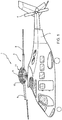
Figure 1 is a side view of a helicopter comprising a rotor according to the present invention; -
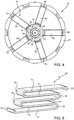
Figure 2 shows a perspective view, on a highly enlarged scale, of a damping device housed in the rotor inFigure 1 ; -
Figure 3 shows an axial section of the rotor inFigure 2 , with parts removed for clarity; -
Figure 4 is a top view of the damping device inFigures 2 and3 ; and -
Figure 5 shows a perspective view, on a highly enlarged scale, of a detail of the damping device inFigures 2 to 4 . Referring toFigure 1 , reference numeral 1 indicates a hover-capable aircraft, in particular a helicopter basically comprising afuselage 2, amain rotor 3 positioned on the top of thefuselage 2 and rotating about an axis A, and atail rotor 4 located at one end of thefuselage 2 and rotating about its own axis, transversal to axis A. - In greater detail, the
rotor 3 comprises (Figure 2 ) ahollow hub 5, with axis A, carrying a plurality of cantilever-mountedblades 9, which extend radially to axis A. - The
rotor 3 also comprises amast 6, rotatable about axis A, angularly integral with thehub 5, and coupled, in a manner not shown, with a drive member, for example a turbine, carried by the helicopter 1. In particular, themast 6 is hollow. - More specifically (
Figure 3 ), themast 6 is partly housed inside thehub 5 and is angularly integral with thehub 5 by means of a splined profile and a pair of wedges radially interposed between themast 6 and thehub 5. In particular, the splined profile is axially interposed between the aforesaid wedges. - The
main rotor 3 also comprises aflow conveyor 10 designed to guide the airflow generated by the rotation of therotor 3 according to a predetermined path shaped so as to limit the vibrations generated by separation of the aforesaid flow from the tips of theblades 9 located on the opposite end to thehub 5. - In greater detail, the
flow conveyor 10 is annular, extends around axis A and is located on the opposite side of thehub 5 with respect to thefuselage 2. - The
flow conveyor 10 has a "hat-like" shape and is delimited by a pair ofsurfaces surface 11 axially delimits theflow conveyor 10 on the opposite side to thehub 5, whilesurface 12 axially delimits theflow conveyor 10 on the side closest to thehub 5. -
Surface 11 is continuous and extends, proceeding in a radial direction starting from axis A, at an axially decreasing distance from thehub 5. -
Surface 12 has a first circularperipheral edge 13 and a second peripheral edge (not shown inFigure 3 ), opposite toedge 13 and arranged radially outermost toperipheral edge 13. Furthermore, the second peripheral edge ofsurface 12 axially faces a peripheral edge ofsurface 11. -
Surfaces - More specifically,
surface 12, when proceeding fromedge 13 towards the second edge, first moves away from thehub 5 and then moves closer to thehub 5. -
Surfaces tubular body 14, symmetrical with respect to axis A and having a lateral surface 8 extending betweensurfaces - The
rotor 3 further comprises a vibration-damping device 15. In particular, thedevice 15 is of the passive type and enables containing transmission to themast 6 of both flexural vibrations in a plane orthogonal to axis A and axial vibrations along axis A, as shall become clear hereinafter in this description. - The
device 15 basically comprises: - a
mass 17 operatively connected to thehub 5 and themast 6 so as to counter the transmission of vibrations generated by the rotation of theblades 9; and - an elastically
deformable rod 16. - The
rod 16 is supported by themast 6 and connected to themass 17, extending at least partly inside themast 6, and stretching parallel to axis A. - More specifically, the flexural stiffness of the
rod 16 in a plane orthogonal to axis A and the size of themass 17 are such that themass 17 vibrates, in use, with a predetermined frequency value, which is associated with the characteristic pulsation of the vibrations generated by rotation of therotor 3 in the reference system integral with thefuselage 2. This value corresponds to a pulse rate of N*Ω, where Ω is the rotation speed of the mast and N represents the number of blades of therotor 3. - In other words, the
rod 16 and themass 17 form a first flexural tuned mass damper, tuned to the frequency of the vibrations generated by therotor 3 and exerting a force on themast 6 such as to counter the transmission of the aforementioned vibrations to themast 6 and, therefore, to the helicopter 1. - It is important to stress that the
rod 16 is configured so as to have high axial stiffness, such that it can be considered as not causing any axial movement of themass 17. - The
rotor 3 also comprises a cup-shaped body 20, with axis A, and angularly integral with themast 6 and therod 16 so as to connect themast 6 and therod 16 to each other. - More specifically, the cup-shaped
body 20 has a tubular form, extending symmetrically about axis A and is radially external to therod 16. - The cup-shaped
body 20 comprises amain portion 22 encircled by themast 6 and stretching parallel to axis A, and anannular head surface 21 lying on plane orthogonal to axis A. - The
main portion 22 defines, on the end opposite to thehead surface 21, aseat 23 engaged by anaxial end 18 of therod 16. - The
rod 16 passes through thehead surface 21, which is axially fastened, by means of a plurality of screws, onto a threadedring nut 29 coupled to themast 6. - The
head surface 21 defines an axial end of the cup-shapedbody 20 facing towards theflow conveyor 10, while theseat 23 is located at an axial end of the cup-shapedbody 20 arranged at the opposite end to thehead surface 21. - A threaded tie rod orthogonal to axis A also passes through the
seat 23 andend 18. - Preferably, the cup-shaped
body 20 is made of light alloy. - The
rod 16 comprises a threadedend 19, opposite to end 18, and on which a nut 25 is screwed. - Finally, the
rod 16 comprises an intermediate section between theends end 18 towardsend 19, and passing through thehead surface 21. -
End 18 of therod 16 is housed inside themast 6. - Moreover, the
rod 16 is completely housed inside the cylinder defined by the prolongation of themast 6 towards theflow conveyor 10. - The
mass 17 is housed inside theflow conveyor 10. In particular, themass 17 is housed inside abay 24 radially delimited by surface 8, axially open towards thehub 5, and axially closed on the opposite side to thehub 5 by the portion ofsurface 11 bounded by surface 8. - Advantageously, the
device 15 comprises a plurality of springs 30 (Figures 2 to 5 ) operatively connected to themass 17 and having a desired stiffness along axis A, so as to contain the transmission of axial vibrations to themast 6. - In other words, the
masses 17 and thesprings 30 form a second tuned mass damper that oscillates along axis A, reducing the axial vibrations of themast 6. - Preferably, the tuning frequency of the second mass damper, formed by the
mass 17 and thesprings 30, is equal to that of the first mass damper, formed by therod 16 and themass 17, and corresponds to a pulse rate of N*Ω. - More specifically, the
springs 30 are interposed between therod 16 and themass 17. - With particular reference to
Figure 5 , eachspring 30 is shaped in a serpentine. - In turn, each
spring 30 comprises: - a plurality of
sections 31 with a mainly radial extension; and - a plurality of
sections 32 with a mainly axial extension, which are interposed between two mutuallyconsecutive sections 31. - In the case shown,
sections 31 are flat andsections 32 are curved so as to join two mutuallyconsecutive sections 31. - In addition, the radial space occupied by
sections 31 is greater than the axial space occupied bysections 32. - Furthermore, each
spring 30 is constrained to themass 17 and therod 16 at its radially free ends 33 ofrespective sections 31 defining opposite axial ends of thespring 30. - The shaping and method of constraining the
springs 30 are such that they can be considered elastically deformable along axis A and having substantially infinite stiffness in the plane orthogonal to axis A, so that thesprings 30 effectively do not cause any vibration of the mass 17 in the plane orthogonal to axis A. - Referring to
Figures 2 and4 , themass 17 is shaped like a hollow cylinder, internally housingaxial end 19 of therod 16 and thesprings 30. - More specifically, the mass 17 houses a first and a
second set springs 30. - Each set 34 and 35 is formed by a plurality of
springs 30, five in the case shown, angularly equi-spaced around axis A. - In particular, the number of
springs 30 of each set 34 and 35 corresponds to the number ofblades 9 of therotor 3. - The
sets springs 30 ofset 34 are arranged in correspondence to therespective springs 30 ofset 35. - The
rod 16 also comprises ahub 40 located atend 19 and to which thesprings 30 are connected. - The
hub 40 connects therod 16 and themass 17 via thesprings 30 in an elastically deformable manner in the direction parallel to axis A. - With particular reference to
Figure 3 , thehub 40 comprises: - a pair of
elements 41 axially opposite to each other and to which the radially inner ends of thesprings 30 of thesets - an
element 42, which is axially interposed betweenelements 41. - In particular, the
mass 17 is made of tungsten.
In the case shown, thehub 40 is pentagonal. - The
mass 17 comprises amain body 26 defining the seat 25 and a plurality of plates 27 (not visible inFigure 2 ) connected in a releasable manner to themain body 26 to enable adjusting the axial vibration frequency of the mass 17 parallel to axis A, and therefore the tuning frequency of thedevice 15 to the N*Ω pulse rate. - The
plates 27 are formed by rings coaxial to axis A, stacked on top of each other and lying on respective planes orthogonal to axis A. - Similarly, the
rod 16 comprises a plurality of plates 45 (not visible inFigure 2 ), connected in a releasable manner to thehub 40 and close to end 19, in order to selectively alter the flexural vibration frequency of the mass 17 in a plane orthogonal to axis A and therefore the tuning frequency of thedevice 15. - In use, the
mast 6 drives thehub 5, theblades 9 and thedevice 15 in rotation about axis A. - The rotation of the
hub 5 and theblades 9 generates aerodynamic loads on theblades 9 and consequent vibrations, which are transmitted to themast 6. - Furthermore, rotation of the
device 15 causes: - flexural oscillation of the mass 17 in the plane orthogonal to axis A, by virtue of the fact that the
rod 16 has flexural elastic pliability, while being substantially rigid in the axial direction; and - axial oscillation of the mass 17 parallel to axis A, by virtue of the fact that the
springs 30 have a desired axial stiffness, while being substantially rigid in the plane orthogonal to axis A. - In other words, the
device 15 behaves substantially like an assembly comprising: - the first tuned mass damper formed by the
rod 16 and themass 17, and able of contain the transmission of flexural vibrations in the plane orthogonal to axis A to themast 6; and - the second tuned mass damper formed by the
springs 30 and themass 17, and able of contain the transmission of axial vibrations to themast 6. - Due to the design configuration of the
rod 16, themass 17 and thesprings 30, the flexural and axial vibration frequencies of themass 17 are such as to be tuned to the fundamental frequency of the vibrations induced by the rotation of therotor 3, namely N*Ω. - Therefore, thanks to the flexural and elastic oscillations of the
mass 17, thedevice 15 counters the transmission of the aforementioned axial and flexural vibrations to themast 6 and, from the latter, to thefuselage 2. - The
device 15 can be easily inserted inside apre-existing rotor 3, comprisinghub 5,mast 6 andblades 9, in order to upgrade therotor 3. - To this end, it is sufficient to fix the cup-shaped
body 20 to themast 6, fix therod 16 to the cup-shapedbody 20 and, lastly, fix themass 17 and thesprings 30 to therod 16. - Finally, the tuning frequency of the
device 15 can be finely adjusted, once thedevice 15 has been installed aboard the helicopter 1, inside therotor 3. - In particular,
plates 27 are first added to themass 17 to tune thedevice 15 to the desired axial vibration frequency of themast 6 that it is wished to contain, equal to N*Ω.
Then,plates 45 are added to thehub 40 so as to tune thedevice 15 to the desired flexural vibration frequency of themast 6 that it is wished to contain, equal to N*Ω. - It is important to stress that
plates 45 adjust the flexural vibration frequency of the system formed by therod 16 and themass 17, but do not substantially alter the axial vibration frequency of the system formed by thesprings 30 and themass 17. - From examination of the
rotor 3 and the method according to the present invention, the advantages that can be achieved therewith are evident. - In particular, the
device 15 comprises thesprings 30, which have a desired stiffness along axis A and are connected to themass 17. - In this way, the
mass 17 can elastically oscillate parallel to axis A, thereby containing the transmission of axial vibrations parallel to axis A to themast 6. - Moreover, the
mass 17 is also free to oscillate in the plane orthogonal to axis A and elastically connected to therod 16 having a desired value of axial stiffness. - Thus, the
device 15 uses thesame mass 17 as a "moveable element" to contain the transmission of both flexural vibrations and axial vibrations to themast 6. - In other words, the
same mass 17 is both part of the first tuned mass damper together with therod 16 and part of the second tuned mass damper together with thesprings 30. - Furthermore, the
device 15 uses thesame rod 16 to connect both the flexural tuned mass damper, formed by themass 17 and therod 16, and the axial tuned mass damper, formed by themass 17 and thesprings 30, to themast 6. - It follows that the
device 15 is particularly compact and takes up little space, making integration in therotor 3 possible without unduly altering the design of latter. - The applicant has also noted that thanks to their serpentine configuration, the
springs 30 have a constant stiffness and therefore a substantially linear elastic behaviour. - In addition, as the
device 15 is housed inside thebay 24, it is not subjected to aerodynamic forces that might prevent thedevice 15 tuning to the aforementioned frequency value characteristic of the vibrations generated by rotation of therotor 3. - Finally, the
device 15 is easily incorporated in therotor 3, as it is housed in thebay 24 and is therefore not intrusive with respect to the other components of therotor 3. - The method of upgrading according to the invention is particularly advantageous, as it does not require modifying a
pre-existing rotor 3 to create new housings for thedevice 15. In fact, to this end, it is sufficient to fix the cup-shapedbody 20 to themast 6, fix therod 16 to the cup-shapedbody 20, and fix thesprings 30 to therod 16 and themass 17 to thesprings 30. - Finally, the tuning frequency of the
device 15 can be easily adjusted once thedevice 15 has been installed in therotor 3, so as to take into account the effective value of the rotation speed Ω of themast 6. - To this end, it is sufficient to first add some
plates 27 to themass 17 to tune thedevice 15 to the desired axial vibration frequency of themast 6, and then add someplates 45 to thehub 40 to tune thedevice 15 to desired flexural vibration frequency of themast 6 that it is wished to contain. - Finally, it is obvious that modifications and variants can be made regarding the
rotor 3 and the method described and illustrated herein without departing from the scope of protection defined by the claims. - In particular, instead of the
springs 30, therotor 3 could comprise one or more flat spring (s) fixed to therod 16 and elastically deformable parallel to axis A. - The helicopter 1 could also be a convertiplane.
Claims (15)
- A rotor (3) for a hover-capable aircraft (1), comprising:- a hub (5) rotatable about a first axis (A) and, in turn, comprising a plurality of blades (9);- a mast (6) connectable to a drive member of said aircraft (1) and operatively connected to said hub (5) to drive the hub (5) in rotation about said axis (A); anddamping means (15) to dampen the transmission of vibrations to said mast (6), which comprise a mass (17) designed to oscillate, in use, in a plane transversal to said axis (A) so as to contain, in use, the flexural vibrations of said mast (6) generated by rotation of the blades (9);
characterized in that said damping means (15) further comprise elastic means (30) possessing a desired stiffness along said axis (A) and operatively connected to said mass (17) to contain, in use, the vibration of said mast (6) along said axis (A). - The rotor according to claim 1, characterized in that said damping means (15) further comprise a first elastic element (16) supported by said mast (6) and designed to flexurally oscillate in a plane transversal to said axis (A);
said first elastic element extending along said axis (A);
said elastic means (30) also being interposed between said mass (17) and said first elastic element (16). - The rotor according to claim 1 or 2, characterized in that said elastic means (30) comprise at least a second elastic element (30) with a serpentine-like shape, having a plurality of first sections (31) extending mainly radially with respect to said axis (A) alternating with a plurality of second sections (32) extending mainly parallel to said axis (A).
- The rotor according to claim 3, characterized in that the radial extension of each said first section (31) is greater than the axial extension of each said second section (32).
- The rotor according to either of claims 3 or 4, characterized in that said elastic means (30) comprise a first plurality (34) of said second elastic elements (30) angularly equi-spaced with respect to said axis (A).
- The rotor according to claim 5, characterized in that said elastic means (30) comprise a second plurality (35) of said second elastic elements (30), which are angularly equi-spaced with respect to said axis (A);
each said second elastic element (30) of said first plurality (34) being axially superimposed on a respective said second elastic element (30) of said second plurality (35). - The rotor according to any of claims 2 to 6, characterized in that said second elastic element (30) comprises a pair of second axial end sections (33) at its free ends, opposite to each other and with one fixed to said mass (17) and the other fixed to said first elastic element (16).
- The rotor according to any of claims 5 to 7, characterized in that it comprises a further hub (40) angularly integral with said first elastic element (16), fitted on an axial end of said elastic element (16) and on which said second elastic elements (30) are fixed.
- The rotor according to any of the preceding claims, characterized in that said mass (17) is hollow and in that said elastic means (30) are housed inside said mass (17).
- The rotor according to any of claims 2 to 9, characterized in that said mass (17) and said elastic means (30) form a first tuned mass damper having a first natural frequency, and in that said mass (17) and said first elastic element (16) form a second tuned mass damper having a second natural frequency equal to said first natural frequency.
- A hover-capable aircraft (1), characterized in that it comprises a rotor (3) according to any of the preceding claims.
- A method for the containment of vibrations transmitted to a mast (6) of a rotor (3) of an aircraft (1);
said rotor (3) comprising:- a hub (5) rotatable about an axis (A) and, in turn, comprising a plurality of blades (9);- said mast (6), which is connectable to a drive member of said aircraft (1) and operatively connected to said hub (5) to drive the hub (5) in rotation about said axis (A);said method comprising the step of:i) connecting a first mass (17) to said mast (6) in a manner free to oscillate in a plane transversal to said axis (A) so as to contain the flexural vibrations of said mast (6);characterized in that it comprises the steps of:ii) connecting elastic means (30) having a desired stiffness along said axis (A) to said mass (17), so as to contain the vibration of said mast (6) along said axis (A). - The method according to claim 12, characterized in that it comprises the steps of:iii) connecting a first elastic element (16) designed to oscillate in a plane transversal to said axis (A) and supported by said mast (6) to said mass (17);iv) connecting said first mass (17) to said first elastic element (16).
- The method according to claim 13, characterized in that it comprises the steps of:v) selectively adding further second masses (27) to said first mass (17) to tune the vibration frequency of said first mass (17) parallel to said axis (A) to a desired value; andvi) selectively adding further third masses (45) to said first elastic element (16) to tune the vibration frequency of said first mass (17) transversely to said axis (A) to said desired value.
- The method according to claim 14, characterized in that said step v) is performed before said step vi).
Priority Applications (6)
| Application Number | Priority Date | Filing Date | Title |
|---|---|---|---|
| EP17199478.3A EP3476728B1 (en) | 2017-10-31 | 2017-10-31 | Rotor for a hover-capable aircraft and method for containment of vibrations transmitted to the mast of a rotor of a hover-capable aircraft |
| PCT/IB2018/058499 WO2019087070A1 (en) | 2017-10-31 | 2018-10-30 | Rotor for a hover-capable aircraft and method for containment of vibrations transmitted to the mast of a rotor of a hover-capable aircraft |
| CN201880069718.2A CN111278731B (en) | 2017-10-31 | 2018-10-30 | Rotor for a hoverable aircraft and method of dampening vibrations transmitted to the main shaft of a rotor for a hoverable aircraft |
| US16/754,270 US11498667B2 (en) | 2017-10-31 | 2018-10-30 | Rotor for a hover-capable aircraft and method for containment of vibrations transmitted to the mast of a rotor of a hover-capable aircraft |
| RU2020114179A RU2764332C9 (en) | 2017-10-31 | 2018-10-30 | Main rotor for aircraft capable of hovering in air and method for containing vibrations transmitted to main rotor shaft of aircraft capable of hovering in air |
| KR1020207014067A KR102618489B1 (en) | 2017-10-31 | 2018-10-30 | Rotor for a hoverable aircraft and method for suppressing vibration transmitted to the mast of the rotor of a hoverable aircraft |
Applications Claiming Priority (1)
| Application Number | Priority Date | Filing Date | Title |
|---|---|---|---|
| EP17199478.3A EP3476728B1 (en) | 2017-10-31 | 2017-10-31 | Rotor for a hover-capable aircraft and method for containment of vibrations transmitted to the mast of a rotor of a hover-capable aircraft |
Publications (2)
| Publication Number | Publication Date |
|---|---|
| EP3476728A1 true EP3476728A1 (en) | 2019-05-01 |
| EP3476728B1 EP3476728B1 (en) | 2019-12-25 |
Family
ID=60781449
Family Applications (1)
| Application Number | Title | Priority Date | Filing Date |
|---|---|---|---|
| EP17199478.3A Active EP3476728B1 (en) | 2017-10-31 | 2017-10-31 | Rotor for a hover-capable aircraft and method for containment of vibrations transmitted to the mast of a rotor of a hover-capable aircraft |
Country Status (5)
| Country | Link |
|---|---|
| US (1) | US11498667B2 (en) |
| EP (1) | EP3476728B1 (en) |
| KR (1) | KR102618489B1 (en) |
| CN (1) | CN111278731B (en) |
| WO (1) | WO2019087070A1 (en) |
Families Citing this family (1)
| Publication number | Priority date | Publication date | Assignee | Title |
|---|---|---|---|---|
| EP3599162B1 (en) * | 2018-07-27 | 2020-11-11 | LEONARDO S.p.A. | Helicopter kit |
Citations (6)
| Publication number | Priority date | Publication date | Assignee | Title |
|---|---|---|---|---|
| US4596513A (en) * | 1985-01-10 | 1986-06-24 | United Technologies Corporation | Helicopter air-spring vibration absorber |
| US5647726A (en) * | 1996-02-15 | 1997-07-15 | Bell Helicopter Textron Inc. | Rotor system vibration absorber |
| US20100296930A1 (en) * | 2009-05-20 | 2010-11-25 | Eurocopter | Concentrated-mass device for reducing vibration generated by a rotorcraft lift rotor, and a rotor hub fitted with such a device |
| US20100296931A1 (en) * | 2009-05-20 | 2010-11-25 | Eurocopter | Distributed-mass device for reducing vibration generated by a rotorcraft lift rotor, and a rotor hub fitted with such a device |
| US20110268573A1 (en) * | 2010-04-30 | 2011-11-03 | Eurocopter | Device for reducing the vibration generated by a rotorcraft lift rotor, and a rotor hub provided with such a device |
| WO2017145073A1 (en) * | 2016-02-22 | 2017-08-31 | Leonardo S.P.A. | Vibration damping device and damping method for a rotor of an aircraft capable of hovering |
Family Cites Families (5)
| Publication number | Priority date | Publication date | Assignee | Title |
|---|---|---|---|---|
| FR2416838A1 (en) * | 1978-02-10 | 1979-09-07 | Aerospatiale | DEVICE TO MITIGATE THE VIBRATIONS OF A GIRAVION ROTOR |
| DE3428820C2 (en) * | 1984-08-04 | 1986-11-06 | Messerschmitt-Bölkow-Blohm GmbH, 8012 Ottobrunn | Vibration isolator |
| DE07861293T1 (en) * | 2007-04-24 | 2011-01-27 | Bell Helicopter Textron, Inc., Fort Worth | ROTOR HUB VIBRATION |
| ITTO20070442A1 (en) | 2007-06-20 | 2008-12-21 | Santino Pancotti | ROTOR FOR A HELICOPTER INCLUDING A VIBRATION DAMPING DEVICE AND ITS REQUALIFICATION METHOD |
| EP2857313B1 (en) * | 2013-10-03 | 2015-12-23 | AGUSTAWESTLAND S.p.A. | Hover aircraft rotor comprising a vibration damping device |
-
2017
- 2017-10-31 EP EP17199478.3A patent/EP3476728B1/en active Active
-
2018
- 2018-10-30 KR KR1020207014067A patent/KR102618489B1/en active Active
- 2018-10-30 US US16/754,270 patent/US11498667B2/en active Active
- 2018-10-30 WO PCT/IB2018/058499 patent/WO2019087070A1/en not_active Ceased
- 2018-10-30 CN CN201880069718.2A patent/CN111278731B/en active Active
Patent Citations (6)
| Publication number | Priority date | Publication date | Assignee | Title |
|---|---|---|---|---|
| US4596513A (en) * | 1985-01-10 | 1986-06-24 | United Technologies Corporation | Helicopter air-spring vibration absorber |
| US5647726A (en) * | 1996-02-15 | 1997-07-15 | Bell Helicopter Textron Inc. | Rotor system vibration absorber |
| US20100296930A1 (en) * | 2009-05-20 | 2010-11-25 | Eurocopter | Concentrated-mass device for reducing vibration generated by a rotorcraft lift rotor, and a rotor hub fitted with such a device |
| US20100296931A1 (en) * | 2009-05-20 | 2010-11-25 | Eurocopter | Distributed-mass device for reducing vibration generated by a rotorcraft lift rotor, and a rotor hub fitted with such a device |
| US20110268573A1 (en) * | 2010-04-30 | 2011-11-03 | Eurocopter | Device for reducing the vibration generated by a rotorcraft lift rotor, and a rotor hub provided with such a device |
| WO2017145073A1 (en) * | 2016-02-22 | 2017-08-31 | Leonardo S.P.A. | Vibration damping device and damping method for a rotor of an aircraft capable of hovering |
Also Published As
| Publication number | Publication date |
|---|---|
| US11498667B2 (en) | 2022-11-15 |
| CN111278731A (en) | 2020-06-12 |
| KR20200100042A (en) | 2020-08-25 |
| US20200298968A1 (en) | 2020-09-24 |
| RU2020114179A3 (en) | 2021-12-14 |
| KR102618489B1 (en) | 2023-12-27 |
| RU2764332C2 (en) | 2022-01-17 |
| CN111278731B (en) | 2023-05-02 |
| RU2020114179A (en) | 2021-10-20 |
| WO2019087070A1 (en) | 2019-05-09 |
| EP3476728B1 (en) | 2019-12-25 |
Similar Documents
| Publication | Publication Date | Title |
|---|---|---|
| US8695917B2 (en) | Vibration damper mechanism, and a flying machine including a carrier structure and a rotor provided with such a mechanism | |
| KR102206795B1 (en) | Hover aircraft rotor comprising a vibration damping device | |
| US8899928B2 (en) | Device for reducing the vibration generated by a rotorcraft lift rotor, and a rotor hub provided with such a device | |
| AU2002332609B2 (en) | Compact vibration cancellation device | |
| ES2231944T3 (en) | VIBRATION ABSORPTION SYSTEMS. | |
| US8469667B2 (en) | Distributed-mass device for reducing vibration generated by a rotorcraft lift rotor, and a rotor hub fitted with such a device | |
| EP2160325B1 (en) | Helicopter rotor comprising a vibration damper | |
| CN100408910C (en) | Variable Stiffness Supports | |
| GB2030949A (en) | Vibration isolation in helicopters | |
| EP3476728B1 (en) | Rotor for a hover-capable aircraft and method for containment of vibrations transmitted to the mast of a rotor of a hover-capable aircraft | |
| US4239456A (en) | Rotor blade out-of-plane centrifugal pendulums | |
| US20210095738A1 (en) | Multiple frequency vibration attenuation device | |
| RU2764332C9 (en) | Main rotor for aircraft capable of hovering in air and method for containing vibrations transmitted to main rotor shaft of aircraft capable of hovering in air | |
| EP2466072B1 (en) | Axial air movement fans | |
| CN114096461B (en) | Rotor for an aircraft capable of hovering | |
| US11203417B2 (en) | Rotorcraft fitted with an antivibration system, and a method of adjusting such an antivibration system | |
| JP2021531194A (en) | Helicopter kit | |
| JPH0253279B2 (en) | ||
| US20220144416A1 (en) | Liquid inertia vibration elimination system with compound period strut |
Legal Events
| Date | Code | Title | Description |
|---|---|---|---|
| PUAI | Public reference made under article 153(3) epc to a published international application that has entered the european phase |
Free format text: ORIGINAL CODE: 0009012 |
|
| STAA | Information on the status of an ep patent application or granted ep patent |
Free format text: STATUS: REQUEST FOR EXAMINATION WAS MADE |
|
| 17P | Request for examination filed |
Effective date: 20180222 |
|
| AK | Designated contracting states |
Kind code of ref document: A1 Designated state(s): AL AT BE BG CH CY CZ DE DK EE ES FI FR GB GR HR HU IE IS IT LI LT LU LV MC MK MT NL NO PL PT RO RS SE SI SK SM TR |
|
| AX | Request for extension of the european patent |
Extension state: BA ME |
|
| GRAP | Despatch of communication of intention to grant a patent |
Free format text: ORIGINAL CODE: EPIDOSNIGR1 |
|
| STAA | Information on the status of an ep patent application or granted ep patent |
Free format text: STATUS: GRANT OF PATENT IS INTENDED |
|
| INTG | Intention to grant announced |
Effective date: 20190712 |
|
| GRAS | Grant fee paid |
Free format text: ORIGINAL CODE: EPIDOSNIGR3 |
|
| GRAA | (expected) grant |
Free format text: ORIGINAL CODE: 0009210 |
|
| STAA | Information on the status of an ep patent application or granted ep patent |
Free format text: STATUS: THE PATENT HAS BEEN GRANTED |
|
| AK | Designated contracting states |
Kind code of ref document: B1 Designated state(s): AL AT BE BG CH CY CZ DE DK EE ES FI FR GB GR HR HU IE IS IT LI LT LU LV MC MK MT NL NO PL PT RO RS SE SI SK SM TR |
|
| REG | Reference to a national code |
Ref country code: GB Ref legal event code: FG4D |
|
| REG | Reference to a national code |
Ref country code: CH Ref legal event code: EP |
|
| REG | Reference to a national code |
Ref country code: DE Ref legal event code: R096 Ref document number: 602017010052 Country of ref document: DE |
|
| REG | Reference to a national code |
Ref country code: AT Ref legal event code: REF Ref document number: 1216849 Country of ref document: AT Kind code of ref document: T Effective date: 20200115 |
|
| REG | Reference to a national code |
Ref country code: IE Ref legal event code: FG4D |
|
| REG | Reference to a national code |
Ref country code: NL Ref legal event code: MP Effective date: 20191225 |
|
| PG25 | Lapsed in a contracting state [announced via postgrant information from national office to epo] |
Ref country code: GR Free format text: LAPSE BECAUSE OF FAILURE TO SUBMIT A TRANSLATION OF THE DESCRIPTION OR TO PAY THE FEE WITHIN THE PRESCRIBED TIME-LIMIT Effective date: 20200326 Ref country code: NO Free format text: LAPSE BECAUSE OF FAILURE TO SUBMIT A TRANSLATION OF THE DESCRIPTION OR TO PAY THE FEE WITHIN THE PRESCRIBED TIME-LIMIT Effective date: 20200325 Ref country code: LT Free format text: LAPSE BECAUSE OF FAILURE TO SUBMIT A TRANSLATION OF THE DESCRIPTION OR TO PAY THE FEE WITHIN THE PRESCRIBED TIME-LIMIT Effective date: 20191225 Ref country code: SE Free format text: LAPSE BECAUSE OF FAILURE TO SUBMIT A TRANSLATION OF THE DESCRIPTION OR TO PAY THE FEE WITHIN THE PRESCRIBED TIME-LIMIT Effective date: 20191225 Ref country code: LV Free format text: LAPSE BECAUSE OF FAILURE TO SUBMIT A TRANSLATION OF THE DESCRIPTION OR TO PAY THE FEE WITHIN THE PRESCRIBED TIME-LIMIT Effective date: 20191225 Ref country code: FI Free format text: LAPSE BECAUSE OF FAILURE TO SUBMIT A TRANSLATION OF THE DESCRIPTION OR TO PAY THE FEE WITHIN THE PRESCRIBED TIME-LIMIT Effective date: 20191225 Ref country code: BG Free format text: LAPSE BECAUSE OF FAILURE TO SUBMIT A TRANSLATION OF THE DESCRIPTION OR TO PAY THE FEE WITHIN THE PRESCRIBED TIME-LIMIT Effective date: 20200325 |
|
| REG | Reference to a national code |
Ref country code: LT Ref legal event code: MG4D |
|
| PG25 | Lapsed in a contracting state [announced via postgrant information from national office to epo] |
Ref country code: RS Free format text: LAPSE BECAUSE OF FAILURE TO SUBMIT A TRANSLATION OF THE DESCRIPTION OR TO PAY THE FEE WITHIN THE PRESCRIBED TIME-LIMIT Effective date: 20191225 Ref country code: HR Free format text: LAPSE BECAUSE OF FAILURE TO SUBMIT A TRANSLATION OF THE DESCRIPTION OR TO PAY THE FEE WITHIN THE PRESCRIBED TIME-LIMIT Effective date: 20191225 |
|
| PG25 | Lapsed in a contracting state [announced via postgrant information from national office to epo] |
Ref country code: AL Free format text: LAPSE BECAUSE OF FAILURE TO SUBMIT A TRANSLATION OF THE DESCRIPTION OR TO PAY THE FEE WITHIN THE PRESCRIBED TIME-LIMIT Effective date: 20191225 |
|
| PG25 | Lapsed in a contracting state [announced via postgrant information from national office to epo] |
Ref country code: EE Free format text: LAPSE BECAUSE OF FAILURE TO SUBMIT A TRANSLATION OF THE DESCRIPTION OR TO PAY THE FEE WITHIN THE PRESCRIBED TIME-LIMIT Effective date: 20191225 Ref country code: CZ Free format text: LAPSE BECAUSE OF FAILURE TO SUBMIT A TRANSLATION OF THE DESCRIPTION OR TO PAY THE FEE WITHIN THE PRESCRIBED TIME-LIMIT Effective date: 20191225 Ref country code: PT Free format text: LAPSE BECAUSE OF FAILURE TO SUBMIT A TRANSLATION OF THE DESCRIPTION OR TO PAY THE FEE WITHIN THE PRESCRIBED TIME-LIMIT Effective date: 20200520 Ref country code: RO Free format text: LAPSE BECAUSE OF FAILURE TO SUBMIT A TRANSLATION OF THE DESCRIPTION OR TO PAY THE FEE WITHIN THE PRESCRIBED TIME-LIMIT Effective date: 20191225 Ref country code: NL Free format text: LAPSE BECAUSE OF FAILURE TO SUBMIT A TRANSLATION OF THE DESCRIPTION OR TO PAY THE FEE WITHIN THE PRESCRIBED TIME-LIMIT Effective date: 20191225 |
|
| PG25 | Lapsed in a contracting state [announced via postgrant information from national office to epo] |
Ref country code: IS Free format text: LAPSE BECAUSE OF FAILURE TO SUBMIT A TRANSLATION OF THE DESCRIPTION OR TO PAY THE FEE WITHIN THE PRESCRIBED TIME-LIMIT Effective date: 20200425 Ref country code: SK Free format text: LAPSE BECAUSE OF FAILURE TO SUBMIT A TRANSLATION OF THE DESCRIPTION OR TO PAY THE FEE WITHIN THE PRESCRIBED TIME-LIMIT Effective date: 20191225 Ref country code: SM Free format text: LAPSE BECAUSE OF FAILURE TO SUBMIT A TRANSLATION OF THE DESCRIPTION OR TO PAY THE FEE WITHIN THE PRESCRIBED TIME-LIMIT Effective date: 20191225 |
|
| REG | Reference to a national code |
Ref country code: DE Ref legal event code: R097 Ref document number: 602017010052 Country of ref document: DE |
|
| PG25 | Lapsed in a contracting state [announced via postgrant information from national office to epo] |
Ref country code: DK Free format text: LAPSE BECAUSE OF FAILURE TO SUBMIT A TRANSLATION OF THE DESCRIPTION OR TO PAY THE FEE WITHIN THE PRESCRIBED TIME-LIMIT Effective date: 20191225 Ref country code: ES Free format text: LAPSE BECAUSE OF FAILURE TO SUBMIT A TRANSLATION OF THE DESCRIPTION OR TO PAY THE FEE WITHIN THE PRESCRIBED TIME-LIMIT Effective date: 20191225 |
|
| PLBE | No opposition filed within time limit |
Free format text: ORIGINAL CODE: 0009261 |
|
| STAA | Information on the status of an ep patent application or granted ep patent |
Free format text: STATUS: NO OPPOSITION FILED WITHIN TIME LIMIT |
|
| REG | Reference to a national code |
Ref country code: AT Ref legal event code: MK05 Ref document number: 1216849 Country of ref document: AT Kind code of ref document: T Effective date: 20191225 |
|
| 26N | No opposition filed |
Effective date: 20200928 |
|
| PG25 | Lapsed in a contracting state [announced via postgrant information from national office to epo] |
Ref country code: AT Free format text: LAPSE BECAUSE OF FAILURE TO SUBMIT A TRANSLATION OF THE DESCRIPTION OR TO PAY THE FEE WITHIN THE PRESCRIBED TIME-LIMIT Effective date: 20191225 |
|
| PG25 | Lapsed in a contracting state [announced via postgrant information from national office to epo] |
Ref country code: SI Free format text: LAPSE BECAUSE OF FAILURE TO SUBMIT A TRANSLATION OF THE DESCRIPTION OR TO PAY THE FEE WITHIN THE PRESCRIBED TIME-LIMIT Effective date: 20191225 Ref country code: PL Free format text: LAPSE BECAUSE OF FAILURE TO SUBMIT A TRANSLATION OF THE DESCRIPTION OR TO PAY THE FEE WITHIN THE PRESCRIBED TIME-LIMIT Effective date: 20191225 |
|
| REG | Reference to a national code |
Ref country code: CH Ref legal event code: PL |
|
| PG25 | Lapsed in a contracting state [announced via postgrant information from national office to epo] |
Ref country code: LU Free format text: LAPSE BECAUSE OF NON-PAYMENT OF DUE FEES Effective date: 20201031 Ref country code: MC Free format text: LAPSE BECAUSE OF FAILURE TO SUBMIT A TRANSLATION OF THE DESCRIPTION OR TO PAY THE FEE WITHIN THE PRESCRIBED TIME-LIMIT Effective date: 20191225 |
|
| REG | Reference to a national code |
Ref country code: BE Ref legal event code: MM Effective date: 20201031 |
|
| PG25 | Lapsed in a contracting state [announced via postgrant information from national office to epo] |
Ref country code: BE Free format text: LAPSE BECAUSE OF NON-PAYMENT OF DUE FEES Effective date: 20201031 Ref country code: LI Free format text: LAPSE BECAUSE OF NON-PAYMENT OF DUE FEES Effective date: 20201031 Ref country code: CH Free format text: LAPSE BECAUSE OF NON-PAYMENT OF DUE FEES Effective date: 20201031 |
|
| PG25 | Lapsed in a contracting state [announced via postgrant information from national office to epo] |
Ref country code: IE Free format text: LAPSE BECAUSE OF NON-PAYMENT OF DUE FEES Effective date: 20201031 |
|
| PG25 | Lapsed in a contracting state [announced via postgrant information from national office to epo] |
Ref country code: TR Free format text: LAPSE BECAUSE OF FAILURE TO SUBMIT A TRANSLATION OF THE DESCRIPTION OR TO PAY THE FEE WITHIN THE PRESCRIBED TIME-LIMIT Effective date: 20191225 Ref country code: MT Free format text: LAPSE BECAUSE OF FAILURE TO SUBMIT A TRANSLATION OF THE DESCRIPTION OR TO PAY THE FEE WITHIN THE PRESCRIBED TIME-LIMIT Effective date: 20191225 Ref country code: CY Free format text: LAPSE BECAUSE OF FAILURE TO SUBMIT A TRANSLATION OF THE DESCRIPTION OR TO PAY THE FEE WITHIN THE PRESCRIBED TIME-LIMIT Effective date: 20191225 |
|
| PG25 | Lapsed in a contracting state [announced via postgrant information from national office to epo] |
Ref country code: MK Free format text: LAPSE BECAUSE OF FAILURE TO SUBMIT A TRANSLATION OF THE DESCRIPTION OR TO PAY THE FEE WITHIN THE PRESCRIBED TIME-LIMIT Effective date: 20191225 |
|
| P01 | Opt-out of the competence of the unified patent court (upc) registered |
Effective date: 20231005 |
|
| PGFP | Annual fee paid to national office [announced via postgrant information from national office to epo] |
Ref country code: DE Payment date: 20251028 Year of fee payment: 9 |
|
| PGFP | Annual fee paid to national office [announced via postgrant information from national office to epo] |
Ref country code: GB Payment date: 20251023 Year of fee payment: 9 |
|
| PGFP | Annual fee paid to national office [announced via postgrant information from national office to epo] |
Ref country code: IT Payment date: 20251003 Year of fee payment: 9 |
|
| PGFP | Annual fee paid to national office [announced via postgrant information from national office to epo] |
Ref country code: FR Payment date: 20251027 Year of fee payment: 9 |