EP3476705A1 - Fender structure for lean vehicle - Google Patents
Fender structure for lean vehicle Download PDFInfo
- Publication number
- EP3476705A1 EP3476705A1 EP18202529.6A EP18202529A EP3476705A1 EP 3476705 A1 EP3476705 A1 EP 3476705A1 EP 18202529 A EP18202529 A EP 18202529A EP 3476705 A1 EP3476705 A1 EP 3476705A1
- Authority
- EP
- European Patent Office
- Prior art keywords
- front wheel
- axis
- body frame
- wall portion
- vehicle
- Prior art date
- Legal status (The legal status is an assumption and is not a legal conclusion. Google has not performed a legal analysis and makes no representation as to the accuracy of the status listed.)
- Granted
Links
Images




Classifications
-
- B—PERFORMING OPERATIONS; TRANSPORTING
- B62—LAND VEHICLES FOR TRAVELLING OTHERWISE THAN ON RAILS
- B62J—CYCLE SADDLES OR SEATS; AUXILIARY DEVICES OR ACCESSORIES SPECIALLY ADAPTED TO CYCLES AND NOT OTHERWISE PROVIDED FOR, e.g. ARTICLE CARRIERS OR CYCLE PROTECTORS
- B62J15/00—Mud-guards for wheels
-
- B—PERFORMING OPERATIONS; TRANSPORTING
- B60—VEHICLES IN GENERAL
- B60G—VEHICLE SUSPENSION ARRANGEMENTS
- B60G5/00—Resilient suspensions for a set of tandem wheels or axles having interrelated movements
- B60G5/02—Resilient suspensions for a set of tandem wheels or axles having interrelated movements mounted on a single pivoted arm, e.g. the arm being rigid
-
- B—PERFORMING OPERATIONS; TRANSPORTING
- B60—VEHICLES IN GENERAL
- B60G—VEHICLE SUSPENSION ARRANGEMENTS
- B60G7/00—Pivoted suspension arms; Accessories thereof
- B60G7/001—Suspension arms, e.g. constructional features
-
- B—PERFORMING OPERATIONS; TRANSPORTING
- B60—VEHICLES IN GENERAL
- B60G—VEHICLE SUSPENSION ARRANGEMENTS
- B60G7/00—Pivoted suspension arms; Accessories thereof
- B60G7/02—Attaching arms to sprung part of vehicle
-
- B—PERFORMING OPERATIONS; TRANSPORTING
- B62—LAND VEHICLES FOR TRAVELLING OTHERWISE THAN ON RAILS
- B62D—MOTOR VEHICLES; TRAILERS
- B62D25/00—Superstructure or monocoque structure sub-units; Parts or details thereof not otherwise provided for
- B62D25/08—Front or rear portions
- B62D25/16—Mud-guards or wings; Wheel cover panels
-
- B—PERFORMING OPERATIONS; TRANSPORTING
- B62—LAND VEHICLES FOR TRAVELLING OTHERWISE THAN ON RAILS
- B62K—CYCLES; CYCLE FRAMES; CYCLE STEERING DEVICES; RIDER-OPERATED TERMINAL CONTROLS SPECIALLY ADAPTED FOR CYCLES; CYCLE AXLE SUSPENSIONS; CYCLE SIDECARS, FORECARS, OR THE LIKE
- B62K5/00—Cycles with handlebars, equipped with three or more main road wheels
- B62K5/02—Tricycles
- B62K5/027—Motorcycles with three wheels
-
- B—PERFORMING OPERATIONS; TRANSPORTING
- B62—LAND VEHICLES FOR TRAVELLING OTHERWISE THAN ON RAILS
- B62K—CYCLES; CYCLE FRAMES; CYCLE STEERING DEVICES; RIDER-OPERATED TERMINAL CONTROLS SPECIALLY ADAPTED FOR CYCLES; CYCLE AXLE SUSPENSIONS; CYCLE SIDECARS, FORECARS, OR THE LIKE
- B62K5/00—Cycles with handlebars, equipped with three or more main road wheels
- B62K5/02—Tricycles
- B62K5/05—Tricycles characterised by a single rear wheel
-
- B—PERFORMING OPERATIONS; TRANSPORTING
- B62—LAND VEHICLES FOR TRAVELLING OTHERWISE THAN ON RAILS
- B62K—CYCLES; CYCLE FRAMES; CYCLE STEERING DEVICES; RIDER-OPERATED TERMINAL CONTROLS SPECIALLY ADAPTED FOR CYCLES; CYCLE AXLE SUSPENSIONS; CYCLE SIDECARS, FORECARS, OR THE LIKE
- B62K5/00—Cycles with handlebars, equipped with three or more main road wheels
- B62K5/08—Cycles with handlebars, equipped with three or more main road wheels with steering devices acting on two or more wheels
-
- B—PERFORMING OPERATIONS; TRANSPORTING
- B62—LAND VEHICLES FOR TRAVELLING OTHERWISE THAN ON RAILS
- B62K—CYCLES; CYCLE FRAMES; CYCLE STEERING DEVICES; RIDER-OPERATED TERMINAL CONTROLS SPECIALLY ADAPTED FOR CYCLES; CYCLE AXLE SUSPENSIONS; CYCLE SIDECARS, FORECARS, OR THE LIKE
- B62K5/00—Cycles with handlebars, equipped with three or more main road wheels
- B62K5/10—Cycles with handlebars, equipped with three or more main road wheels with means for inwardly inclining the vehicle body on bends
-
- B—PERFORMING OPERATIONS; TRANSPORTING
- B60—VEHICLES IN GENERAL
- B60G—VEHICLE SUSPENSION ARRANGEMENTS
- B60G2300/00—Indexing codes relating to the type of vehicle
- B60G2300/12—Cycles; Motorcycles
- B60G2300/122—Trikes
-
- B—PERFORMING OPERATIONS; TRANSPORTING
- B62—LAND VEHICLES FOR TRAVELLING OTHERWISE THAN ON RAILS
- B62D—MOTOR VEHICLES; TRAILERS
- B62D61/00—Motor vehicles or trailers, characterised by the arrangement or number of wheels, not otherwise provided for, e.g. four wheels in diamond pattern
- B62D61/06—Motor vehicles or trailers, characterised by the arrangement or number of wheels, not otherwise provided for, e.g. four wheels in diamond pattern with only three wheels
- B62D61/065—Motor vehicles or trailers, characterised by the arrangement or number of wheels, not otherwise provided for, e.g. four wheels in diamond pattern with only three wheels with single rear wheel
Definitions
- the present invention relates to a leaning vehicle including two front wheels that are aligned side by side in a left-and-right direction.
- WO2015/002169 describes a leaning vehicle that includes a right front wheel and a left front wheel that are aligned side by side in a left-and-right direction and shock absorbing devices provided between the right front wheel and the left front wheel.
- This leaning vehicle includes a parallelogram-type link mechanism and leans to the right of the vehicle when turning right, while leaning to the left of the vehicle when turning left.
- a space is provided directly below a cross member of the link mechanism and between the right front wheel and the left front wheel (hereinafter, referred to as a steering allowable space).
- the inventor of the invention has studied about a leaning vehicle that differs from the leaning vehicle described in WO2015/002169 in that a right shock absorbing device is provided to the right of a right front wheel and a left shock absorbing device is provided to the left of a left shock absorbing device. Then, the inventor has come to notice that the leaning vehicle so studied tends to cause easily a problem in that a rider of the leaning vehicle is splashed with water that the right front wheel and the left front wheel splash up.
- It is an object of the invention is to provide a leaning vehicle in which water splashed up by a left front wheel and a right front wheel is prevented from passing in front of the vehicle so that the water is prevented from being scattered to an upper portion of a front portion of the vehicle while restraining an enlargement in size of the vehicle.
- said object is solved by a vehicle having the features of independent claim 1. Preferred embodiments are laid down in the dependent claims.
- a leaning vehicle having:
- the inventor of the invention has considered that an amount of water that enters the steering allowable space is reduced to reduce water that scatters to the front from the steering allowable space.
- Providing a cover that covers the right front wheel when seen in the right axle axis direction at the left side of the right front wheel and a cover that covers the left front wheel when seen in the left axle axis direction at the right of the left front wheel can cut off water that attempts to enter the steering allowable space from the right front wheel and the left front wheel.
- this approach restricts greatly the design of the leaning vehicle.
- the covers move greatly as the right front wheel and the left front wheel are turned, leading to an enlargement in size of the vehicle in relation to the left-and-right direction.
- the inventor of the invention has observed thoroughly how water splashed by the front wheels scatters or flies.
- Water on the road surface adheres to a ground contact surface of a tire first.
- An inertial force is given to the water that adheres to the ground contact surface of the tire as the tire rotates. It has been found out that due to the effect of the inertial force, the water that adheres to the ground contact surface of the tire leaves from the ground contact surface at a point in time when the tire rotates a quarter of one rotation at an earliest timing, and that almost no water leaves from the ground contact surface at a point in time when the tire rotates a half of one rotation.
- Water that leaves from a ground contact point flies substantially towards a tangential direction of the ground contact surface when seen from the axle axis direction. Namely, water leaving the ground contact surface at a point in time when the tire rotates a quarter of one rotation flies upwards, and water leaving the ground contact surface at a point in time later than the point in time when the tire rotates a quarter of one rotation flies further forwards than the water that flew at the point in time when the tire rotates a quarter of one rotation.
- water that leaves from the ground contact surface also flies to the right or left of the vehicle although a main stream thereof flies in a direction that is contained in an imaginary rotational plane of the front wheels.
- a right guide wall portion and a left guide wall portion are provided in upper rear areas on sides of the front wheels when the front wheels are imaginarily divided into four uniform areas in the up-and-down direction and the front-and-rear direction when seen in the axle axis direction.
- water splashed up by the right front wheel hits the right guide wall portion to adhere to the right guide wall portion.
- the water that adheres to the right guide wall portion then flows directly downwards over the right guide wall portion without entering the steering allowable space.
- water splashed up by the left front wheel hits the left guide wall portion to flow directly downwards over the left guide wall portion without entering the steering allowable space.
- providing the right guide wall portion only at part of the right fender can prevent water from entering the steering allowable space and can also prevent an enlargement in size of the right fender.
- an enlargement in size of the left fender can also be prevented. This can also prevent an enlargement in size of the vehicle.
- At least part of a lower edge of the right guide wall portion may be positioned on the left in the right axle axis direction of a leftmost edge in the right axle axis direction of part of the right front wheel, and at least part of a lower edge of the left guide wall portion may be provided on the right in the left axle axis direction of a rightmost edge in the left axle axis direction of part of the left front wheel.
- the right fender may have in an upper front area of the right front wheel a right gradually changing wall portion that connects to the right guide wall portion and in which a dimension that extends inwards towards the right axle axis gradually increase so as to come close to a dimension that extends inwards of the right guide wall portion
- the left fender may have in an upper front area of the left front wheel a left gradually changing wall portion that connects to the left guide wall portion and in which a dimension that extends inwards towards the left axle axis increases gradually so as to come close to a dimension that extends inwards of the left guide wall portion.
- the left and right gradually changing wall portions contribute to improving rigidities of the left and right guide wall portions so as to suppress a deformation of the left and right guide wall portions, thereby making it possible to allow water to fall down onto the ground in an ensured fashion.
- a right guide groove may be provided on a left surface of the right guide wall portion so as to guide water adhering thereto to flow downwards
- a left guide groove may be provided on a right surface of the left guide wall portion so as to guide water adhering thereto to flow downwards.
- water is allowed to guide downwards along the right guide groove and the left guide groove so as to fall down onto the ground in an ensured fashion.
- the right guide wall portion may extend from the outer edge of the right front wheel further inwards than a shoulder portion of the right front wheel when seen from the left in the right axle axis direction
- the left guide wall portion may extend from the outer edge of the left front wheel further inwards than a shoulder portion of the left front wheel when seen from the right in the left axle axis direction.
- water adhering to the right guide wall portion and the left guide wall portion is allowed to guide downwards so as to fall down onto the ground in a more ensured fashion.
- the leaning vehicle in which water splashed up by the left front wheel and the right front wheel is prevented from passing in front of the vehicle so that the water is prevented from being scattered to the upper portion of the front portion of the vehicle while restraining an enlargement in size of the vehicle.
- an arrow F denotes ahead of a vehicle.
- An arrow B denotes behind of the vehicle.
- An arrow U denotes above the vehicle.
- An arrow D denotes below the vehicle.
- An arrow R denotes on the right of the vehicle.
- An arrow L denotes on the left of the vehicle.
- a vehicle turns with a body frame leaning in a left-and-right direction of the vehicle relative to a vertical direction. Then, in addition to the directions based on the vehicle, directions based on the vehicle body frame are defined.
- an arrow FF denotes a front of the vehicle body frame.
- An arrow FB denotes a behind of the vehicle body frame.
- An arrow FU denotes above the vehicle body frame.
- An arrow FD denotes below the vehicle body frame.
- An arrow FR denotes on the right of the vehicle body frame.
- An arrow FL denotes on the left of the vehicle body frame.
- a "front-and-rear direction of the body frame,” a “left-and-right direction of the body frame” and an “up-and-down direction of the body frame” means a front-and-rear direction, a left-and-right direction and an up-and-down direction based on the body frame as viewed from a rider who rides the vehicle.
- the side of the body frame denotes on the right or the on the left of the body frame.
- an expression reading "something extends in the front-and-rear direction of the vehicle body frame" includes a situation in which something extends in the front-and-rear direction of the vehicle body frame while being inclined in relation to the front-and-rear direction of the vehicle body frame and means that something extends with a gradient which is closer to the front-and-rear direction of the vehicle body frame rather than the left-and-right direction and the up-and-down direction of the vehicle body frame.
- an expression reading "something extends in the left-and-right direction of the vehicle body frame” includes a situation in which something extends in the left-and-right direction of the vehicle body frame while being inclined in relation to the left-and-right direction of the vehicle body frame and means that something extends with a gradient which is closer to the left-and-right direction of the vehicle body frame rather than the front-and-rear direction and the up-and-down direction of the vehicle body frame.
- an expression reading "something extends in the up-and-down direction of the vehicle body frame" includes a situation in which something extends in the up-and-down direction of the vehicle body frame while being inclined in relation to the up-and-down direction of the vehicle body frame and means that something extends with a gradient which is closer to the up-and-down direction of the vehicle body frame rather than the front-and-rear direction and the left-and-right direction of the vehicle body frame.
- an "upright state of the vehicle” or the “vehicle stands upright” means a state in which the vehicle remains not steered and the up-and-down direction of the body frame coincides with a vertical direction, In this state, the direction based on the vehicle coincides with the direction based on the body frame.
- the left-and-right direction of the vehicle does not coincide with the left-and-right direction of the body frame.
- the up-and-down direction of the vehicle does not coincide with the up-and-down direction of the body frame, too.
- the front-and-rear direction of the vehicle coincides with the front-and-rear direction of the body frame.
- rotation or rotating means that a member is displaced at an angle of 360 degrees or more about a center axis thereof.
- turn or turning means that a member is displaced at an angle of less than 360 degrees about a center axis thereof.
- a leaning vehicle 1 is a vehicle that is driven by means of power generated from a power source and that includes a body frame that can lean and two front wheels that are aligned side by side in a left-and-right direction of the body frame.
- Fig. 1 is a left side view of the whole of the leaning vehicle 1 as seen from the left thereof.
- the leaning vehicle 1 includes a vehicle main body portion 2, a pair of left and right front wheels 3, a rear wheel 4, a link mechanism 5 and a steering force transmission mechanism 6.
- the vehicle main body portion 2 includes a body frame 21, a body cover 22, a seat 24 and an engine unit 25.
- the leaning vehicle 1 is standing in an upright state.
- the following description which will be made by reference to Fig. 1 is based on the premise that the leaning vehicle 1 is standing or staying in the upright state.
- the body frame 21 extends in a front-and-rear direction of the leaning vehicle 1.
- the body frame 21 includes a headpipe 211 and a link supporting portion 212.
- the headpipe 211 supports an upstream side steering shaft 60, which will be described later, so as to turn.
- the headpipe 211 extends in an up-and-down direction of the body frame 21.
- the link supporting portion 212 is provided ahead of the headstock 211 in the front-and-rear direction of the leaning vehicle 1.
- the link supporting portion 212 supports the link mechanism 5 so as to turn.
- the body frame 21 supports the engine unit 25 behind the headstock 211 in the front-and-rear direction of the leaning vehicle 1.
- the engine unit 25 supports the rear wheel 4 so as to swing up and down.
- the engine unit 25 includes a power source such as an engine or an electric motor with a battery and a device such as a transmission. The power source generates a force by which the leaning vehicle 1 is driven.
- the body cover 22 includes a front cover 221, a pair of left and right front fenders 223 and a rear fender 224.
- the body cover 22 is a body part that covers at least part of body parts that are mounted on the leaning vehicle 1 such as the pair of left and right front wheels 3, the body frame 21, the link mechanism 5 and the like.
- the front cover 221 is disposed ahead of the seat 24.
- the front cover 221 covers the link mechanism 5 and at least part of the steering force transmission mechanism 6.
- At least portions of the pair of left and right front fenders 223 are individually disposed directly below the front cover 221. At least the portions of the pair of left and right front fenders 223 are disposed directly above the pair of left and right front wheels 3, respectively.
- At least portion of the rear fender 224 is disposed directly above the rear wheel 4.
- At least portions of the pair of left and right front wheels 3 are disposed directly below the front cover 221.
- At least a portion of the rear wheel 4 is disposed below the seat 24. At least a portion of the rear wheel 4 is disposed directly below the rear fender 224.
- Fig. 2 is a front view of the front portion of the leaning vehicle 1 as viewed from the front of the body frame 21.
- the leaning vehicle 1 is standing in the upright state.
- the following description which will be made by reference to Fig. 2 is based on the premise that the leaning vehicle 1 is standing or staying in the upright state.
- Fig. 2 shows the front portion of the leaning vehicle 1 as it were seen through the front cover 221 that is indicated by dashed lines.
- the pair of left and right front wheels 3 include a left front wheel 31 and a right front wheel 32.
- the left front wheel 31 and the right front wheel 32 are provided in the left-and-right direction of the vehicle body frame 21.
- the right front wheel 32 is provided on the right of the left front wheel 31 on the body frame 21.
- the leaning vehicle 1 includes a left shock absorbing device 33, a right shock absorbing device 34, a left bracket 317 and a right bracket 327.
- Fig. 3 is a side view showing the left shock absorbing device 33 and the left front wheel 31. Since the right shock absorbing device 34 has a structure symmetrical with the left shock absorbing device 33 in the left-right symmetrical manner, the reference numbers showing the elements of the right shock absorbing device 34 are also added in Fig 3 .
- the left shock absorbing device 33 is a so-called telescopic shock absorbing device,
- the left shock absorbing device 33 has a left front telescopic element 331, a left rear telescopic element 332 and a left inner connecting element 337.
- the left front telescopic element 331 has a left front outer tube 333 and a left front inner tube 334.
- a lower portion of the left front inner tube 334 is connected to a left inner connecting element 337.
- An upper portion of the left front inner tube 334 is inserted into the left front outer tube 333.
- An upper portion of the left front outer tube 333 is connected to the left bracket 317.
- the left front inner tube 334 is displaced relative to the left front outer tube 333 along a left extension and contraction axis c which extends in the up-and-down direction of the body frame 21.
- the left front telescopic element 331 can extend and contract in the direction of the left extension and contraction axis c as a result of the left front inner tube 334 being displaced relative to the left front outer tube 333 along the left extension and contraction axis c.
- the left rear telescopic element 332 is provided behind the left front telescopic element 331.
- the left rear telescopic element 332 has a left rear outer tube 335 and a left rear inner tube 336.
- the left rear outer tube 335 and the left front outer tube 333 are connected together so as not to move relative to each other.
- a lower portion of the left rear inner tube 336 is connected to a left inner connecting element 337.
- An upper portion of the left rear inner tube 336 is inserted into the left rear outer tube 335.
- An upper portion of the left rear outer tube 335 is connected to the left bracket 317.
- the left rear inner tube 336 is displaced relative to the left rear outer tube 335 along the left extension and contraction axis c which extends in the up-and-down direction of the body frame 21.
- the left rear telescopic element 332 can extend and contract in the direction of the left extension and contraction axis c as a result of the left rear inner tube 336 being displaced relative to the left rear outer tube 335 along the left extension and contraction axis c.
- the left inner connecting element 337 supports a left axle member 311 of the left front wheel 31 rotatably.
- the left inner connecting element 337 connects a lower portion of the left front inner tube 334 and a lower portion of the left rear inner tube 336 together.
- the left shock absorbing device 33 attenuates or absorbs a displacement of the left front wheel 31 relative to the left front outer tube 333 and the left rear outer tube 335 along the left extension and contraction axis c by an extending or contracting action of the left front telescopic element 331 and an extending or contracting action of the left rear telescopic element 332.
- the right shock absorbing device 34 is a so-called telescopic shock absorbing device.
- the right shock absorbing device 34 has a right front telescopic element 341, a right rear telescopic element 342 and a right inner connecting element 347.
- the right front telescopic element 341 has a right front outer tube 343 and a right front inner tube 344.
- a lower portion of the right front inner tube 344 is connected to a right inner connecting element 347.
- An upper portion of the right front inner tube 344 is inserted to a right front outer tube 343.
- An upper portion of the right front outer tube 343 is connected to the right bracket 327.
- the right inner tube 344 displaces along with a right extension and contraction axis d which extends in the up-and-down direction of the vehicle body frame 21.
- the right front telescopic element 341 can extend and contract in the direction of the right extension and contraction axis d as a result of the right front inner tube 344 being displaced relative to the right front outer tube 343 along the right extension and contraction axis d.
- the right rear telescopic element 342 has a right rear outer tube 345 and a right rear inner tube 346.
- the right rear outer tube 345 and the right front outer tube 343 are connected together so as not to move relative to each other.
- a lower portion of the right rear inner tube 346 is connected to a rear inner connecting element 347.
- An upper portion of the right rear inner tube 346 is inserted to the right rear outer tube 345.
- An upper portion of the right rear outer tube 345 is connected to the right bracket 327.
- the right rear inner tube 346 displaces along with the right extension and contraction axis d which extends in the up-and-down direction of the vehicle body frame 21.
- the right rear telescopic element 342 can extend and contract in the direction of the right extension and contraction axis d as a result of the right rear inner tube 346 being displaced relative to the right rear outer tube 345 along the right extension and contraction axis d.
- the right inner connecting element 347 supports a right axle member 321 of the right front wheel 32 rotatably.
- the right inner connecting element 347 connects a lower portion of the right front inner tube 344 and a lower portion of the right rear inner tube 346 together.
- the right shock absorbing device 34 attenuates or absorbs the displacement of the right front wheel 32 relative to the right front outer tube 343 and the right rear outer tube 345 along the right extension and contraction axis d by an extending or contracting action of the right front telescopic element 341 and an extending or contracting action of the right rear telescopic element 342.
- the leaning vehicle 1 includes the steering force transmission mechanism 6.
- the steering force transmission mechanism 6 includes a handlebar 23 (an example of a steering force input portion), the upstream side steering shaft 60 (an example of a rear shaft member), a connecting member 80, and a downstream side steering shaft 68 (an example of a front shaft member).
- the body frame 21 includes the headpipe 211 that supports the upstream side steering shaft 60 so as to turn and the link supporting portion 212 that supports the downstream side steering shaft 68 so as to turn.
- the link supporting portion 212 extends in the direction of a middle steering axis Z which extends in the up-and-down direction of the body frame 21.
- a turning center (a central steering axis) of the handlebar 23 coincides with a turning center (a rear axis) of the upstream side steering shaft.
- a steering force is inputted into the handlebar 23.
- the upstream side steering shaft 60 is connected to the handlebar 23.
- the upper portion of the upstream side steering shaft 60 is positioned behind the lower portion of the upstream side steering shaft 60 in the front-and-rear direction of the vehicle body frame 21.
- the upstream side steering shaft 60 is supported in the headpipe 211 so as to turn therein.
- the connecting member 80 connects the upstream side steering shaft 60 and the downstream side steering shaft 68 together.
- the connecting member 80 is displaced as the upstream side steering shaft 60 turns.
- the connecting member 80 transmits the turning of the upstream side steering shaft 60 to the downstream side steering shaft 68.
- the downstream side steering shaft 68 is supported in the link supporting portion 212 so as to turn therein.
- the downstream side steering shaft 68 is connected to the connecting member 80.
- the downstream side steering shaft 68 is provided ahead of the upstream side steering shaft 60 in the front-and-rear direction of the body frame 21.
- the downstream side steering shaft 68 turns in accordance with the displacement of the connecting member 80.
- the left front wheel 31 and the right front wheel 32 are steered or turned via a tie-rod 67.
- the steering force transmission mechanism 6 transmits a steering force exerted on a handlebar 23 by the rider when operating the handlebar 23 to the left bracket 317 and the right bracket 327. A specific configuration will be described in detail later.
- the link mechanism 5 adopts a four parallel joint link system (also referred to as a parallelogram link).
- the link mechanism 5 is disposed above the left front wheel 31 and the right front wheel 32.
- the link mechanism 5 includes an upper cross member 51, a lower cross member 52, a left side member 53 and a right side member 54.
- the link mechanism 5 is turnably supported on the link supporting portion 212 which extends to the middle steering axis Z. Even though the upstream side steering shaft 60 is turned as a result of the operation of the handlebar 23, the link mechanism 5 is prevented from following the turning of the upstream side steering shaft 60 and hence does not turn.
- the upper cross member 51 includes a plate member 512.
- the plate member 512 is provided ahead of the link supporting portion 212.
- the plate member 512 extends in a left-and-right direction of the body frame 21.
- a middle portion of the upper cross member 51 is connected to the link supporting portion 212 by a connecting portion C.
- the upper cross member 51 can turn relative to the link supporting portion 212 about a middle upper axis Mu that passes through the connecting portion C to extend in the front-and-rear direction of the body frame 21.
- a left end portion of the upper cross member 51 is connected to the left side member 53 by a connecting portion A.
- the upper cross member 51 can turn relative to the left side member 53 about a left upper axis which passes through the connecting portion A to extend in the front-and-rear direction of the body frame 21.
- a right end portion of the upper cross member 51 is connected to the right side member 54 by a connecting portion E.
- the upper cross member 51 can turn relative to the right side member 54 about a right upper axis that passes through the connecting portion E to extend in the front-and-rear direction of the body frame 21.
- Fig. 4 is a plan view of the front portion of the leaning vehicle 1 as viewed from above the body frame 21.
- the leaning vehicle 1 is standing in the upright state.
- the following description which will be made by reference to Fig. 4 is based on the premise that the leaning vehicle 1 is standing or staying in the upright state.
- the lower cross member 52 includes a lower front cross element 522a and a lower rear cross element 522b.
- the lower front cross element 522a is provided ahead of the link supporting portion 212.
- the lower rear cross element 522b is provided behind the link supporting portion 212.
- the lower front cross element 522a and the lower rear cross member 522b extend in the left-and-right direction of the body frame 21.
- the lower front cross element 522a and the lower rear cross member 522b are connected together by a left connecting block 523a and a right connecting block 532b.
- the left connecting block 523a is disposed on the left of the link supporting portion 212.
- the right connecting block 523b is disposed on the right of the link supporting portion 212.
- the lower cross member 52 is disposed below the upper cross member 51.
- the lower cross member 52 extends parallel to the upper cross member 51.
- a middle portion of the lower cross member 52 is connected to the link supporting portion 212 by a connecting portion I.
- the lower cross member 52 can turn about a middle down or lower axis Md that passes through the connecting portion I to extend in the front-and-rear direction of the body frame 21.
- a left end portion of the lower cross member 52 is connected to the left side member 53 by a connecting portion G.
- the lower cross member 52 can turn about a left lower axis which passes through the connecting portion G to extend in the front-and-rear direction of the body frame 21.
- a right end portion of the lower cross member 52 is connected to the right side member 54 by a connecting portion H.
- the lower cross member 52 can turn about a right lower axis which passes through the connecting portion H to extend in the front-and-rear direction of the body frame 21.
- a length of the upper cross member 51 from the connecting portion E to the connecting portion A is substantially equal to a length of the lower cross member from the connecting portion H to the connecting portion G.
- the middle upper axis Mu, the right upper axis, the left upper axis, the middle lower axis Md, the right lower axis and the left lower axis extend parallel to one another.
- the middle upper axis Mu, the right upper axis, the left upper axis, the middle lower axis Md, the right lower axis and the left lower axis are disposed above the left front wheel 31 and the right front wheel 32.
- the left side member 53 is disposed on the left of the link supporting portion 212.
- the left side member 53 is disposed above the left front wheel 31.
- the left side member 53 extends parallel to the middle steering axis Z of the link supporting portion 212.
- An upper portion of the left side member 53 is disposed behind a lower portion thereof.
- a lower portion of the left side member 53 is connected to the left bracket 317.
- the left bracket 317 can turn about a left steering axis X relative to the left side member 53.
- the left steering axis X extends parallel to the middle steering axis Z of the link supporting portion 212.
- the right side member 54 is disposed on the right of the link supporting portion 212.
- the right side member 54 is disposed above the right front wheel 32.
- the right side member 54 extends parallel to the middle steering axis Z of the link supporting portion 212.
- An upper portion of the right side member 54 is disposed behind a lower portion thereof.
- a lower portion of the right side member 54 is connected to the right bracket 327.
- the right bracket 327 can turn about a right steering axis Y relative to the right side member 54.
- the right steering axis Y extends parallel to the middle steering axis Z of the link supporting portion 212,
- the upper cross member 51, the lower cross member 52, the left side member 53 and the right side member 54 are supported by the link supporting portion 212 so that the upper cross member 51 and the lower cross member 52 are held in postures which are parallel to each other and so that the left side member 53 and the right side member 54 are held in postures which are parallel to each other.
- the steering force transmission mechanism 6 includes a middle transmission plate 61, a left transmission plate 62, a right transmission plate 63, a middle joint 64, a left joint 65, a right joint 66, and the tie-rod 67.
- the middle transmission plate 61 is connected to a lower portion of the downstream side steering shaft 68.
- the middle transmission plate 61 cannot turn relative to the downstream side steering shaft 68.
- the middle transmission plate 61 can turn about the middle steering axis Z relative to the link supporting portion 212.
- the left transmission plate 62 is disposed on the left of the middle transmission plate 61.
- the left transmission plate 62 is connected to the left bracket 317.
- the left transmission plate 62 cannot turn relative to the left bracket 317.
- the left transmission plate 62 can turn about the left steering axis X relative to the left side member 53.
- the right transmission plate 63 is disposed on the right of the middle transmission plate 61.
- the right transmission plate 63 is connected to the right bracket 327.
- the right transmission plate 63 cannot turn relative to the right bracket 327.
- the right transmission plate 63 can turn about the right steering axis Y relative to the right side member 54.
- the middle joint 64 is connected to a front portion of the middle transmission plate 61 via a shaft portion that extends in the up-and-down direction of the body frame 21.
- the middle transmission plate 61 and the middle joint 64 are allowed to turn relative to each other about this shaft portion.
- the left joint 65 is disposed directly on the left of the middle joint 64.
- the left joint 65 is connected to a front portion of the left transmission plate 62 via a shaft that extends in the up-and-down direction of the body frame 21.
- the left transmission plate 62 and the left joint 65 are allowed to turn relative to each other about this shaft portion.
- the right joint 66 is disposed directly on the right of middle joint 64.
- the right joint 66 is connected to a front portion of the right transmission plate 63 via a shaft that extends in the up-and-down direction of the body frame 21.
- the right transmission plate 63 and the right joint 66 are allowed to turn relative to each other about this shaft portion.
- a shaft portion that extends in the front-and-rear direction of the body frame 21 is provided at a front portion of the middle joint 64.
- a shaft portion that extends in the front-and-rear direction of the body frame 21 is provided at a front portion of the left joint 65.
- a shaft portion that extends in the front-and-rear direction of the body frame 21 is provided at a front portion of the right joint 66.
- the tie-rod 67 extends in the left-and-right direction of the body frame 21.
- the tie-rod 67 is connected to the middle joint 64, the left joint 65 and the right joint 66 via those shaft portions.
- the tie rod 67 and the intermediate joint 64 can turn relatively about the shaft portion which is provided at the front portion of the intermediate joint 64.
- the tie-rod 67 and the left joint 65 can turn relative to each other about the shaft portion that is provided at the front portion of the left joint 65.
- the tie rod 67 and the right joint 66 can turn relative to each other about the shaft portion that is provided at the front portion of the right joint 66.
- FIG. 5 is a plan view, as seen from above the body frame 21, of the front portion of the leaning vehicle 1 with the left front wheel 31 and the right front wheel 32 steered or turned to the left.
- the upstream side steering shaft 60 turns.
- the turn of the upstream side steering shaft 60 is transmitted to the downstream side steering shaft 68 via the connecting member 80.
- the downstream side steering shaft 68 turns relative to the link supporting portion 212 about a front steering axis b.
- the middle transmission plate 61 turns relative to the link supporting portion 212 in a direction indicated by an arrow T about the front steering axis b.
- the middle joint 64 of the tie-rod 67 turns relative to the middle transmission plate 61 in a direction indicated by an arrow S. This moves the tie-rod 67 left rear with its posture kept unchanged.
- the left joint 65 and the right joint 66 of the tie-rod 67 turn in the direction indicated by the arrow S relative to the left transmission plate 62 and the right transmission plate 63, respectively.
- the left bracket 317 which cannot turn relative to the left transmission plate 62, turns in the direction indicated by the arrow T about the left steering axis X relative to the left side member 53.
- the left shock absorbing device 33 When the left bracket 317 turns in the direction indicated by the arrow T, the left shock absorbing device 33, which is connected to the left bracket 317 via the left front outer tube 333 and the left rear outer tube 335, turns in the direction indicated by the arrow T about the left steering axis X relative to the left side member 53.
- the left shock absorbing device 33 turns in the direction indicated by the arrow T
- the left front wheel 31, which is supported on the left shock absorbing device 33 turns in the direction indicated by the arrow T about the left steering axis X relative to the left side member 53.
- the right shock absorbing device 34 When the right bracket 327 turns in the direction indicated by the arrow T, the right shock absorbing device 34, which is connected to the right bracket 327 via the right front outer tube 343 and the right rear outer tube 345, turns in the direction indicated by the arrow T about the right steering axis Y relative to the right side member 54.
- the right shock absorbing device 34 turns in the direction indicated by the arrow T
- the right front wheel 32 which is supported on the right shock absorbing device 34, turns in the direction indicated by the arrow T about the right steering axis Y relative to the right side member 54.
- the steering force transmission mechanism 6 transmits the steering force accordingly to the left front wheel 31 and the right front wheel 32.
- the left front wheel 31 and the right front wheel 32 turn about the left steering axis X and the right steering axis Y, respectively, in the direction corresponding to the direction in which the handlebar 23 is operated by the rider.
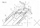
- FIG. 6 is a front view, as seen from the front of the body frame 21, of the front portion of the leaning vehicle 1 with the body frame 21 caused to lean to the left of the leaning vehicle 1.
- Fig. 6 shows a state in which the front portion of the leaning vehicle 1 is seen as through the front cover 221 that is indicated by dashed lines.
- the link mechanism 5 looks like having a rectangular shape.
- the link mechanism 5 looks like having a parallelogram shape.
- the link mechanism 5 deforms as the body frame 21 leans in the left-and-right direction of the leaning vehicle 1.
- the operation of the link mechanism 5 means that the upper cross member 51, the lower cross member 52, the left side member 53 and the right side member 54 that make up the link mechanism 5 turn relatively about turning axes which pass through the corresponding connecting portions A, C. E, G, H, I, whereby the shape of the link mechanism 5 changes.
- the link supporting portion 212 leans to the left relative to the perpendicular direction.
- the upper cross member 51 turns counterclockwise as seen from the front of the leaning vehicle 1 about the middle upper axis Mu that passes through the connecting portion C relative to the link supporting portion 212.
- the lower cross member 52 turns counterclockwise as seen from the front of the leaning vehicle 1 about the middle lower axis Md that passes through the connecting portion I relative to the link supporting portion 212. This causes the upper cross member 51 to move to the left relative to the lower cross member 52.
- the upper cross member 51 moves to the left, the upper cross member 51 turns counterclockwise as seen from the front of the leaning vehicle 1 about the left upper axis that passes through the connecting portion A and the right upper axis that passes through the connecting portion E relative to the left side member 53 and the right side member 54, respectively.
- the lower cross member 52 turns counterclockwise as seen from the front of the leaning vehicle 1 about the left lower axis that passes through the connecting portion G and the right lower axis that passes through the connecting portion H relative to the left side member 53 and the right side member 54, respectively. This causes the left side member 53 and the right side member 54 to lean to the left relative to the perpendicular direction with their postures kept parallel to the link supporting portion 212.
- the lower cross member 52 moves to the left relative to the tie- rod 67.
- the shaft portions that are provided at the respective front portions of the middle joint 64, the left joint 65 and the right joint 66 turn relative to the-tie rod 67. This allows the tie-rod 67 to hold a parallel posture to the upper cross member 51 and the lower cross member 52.
- the left bracket 317 which is connected to the left side member 53, leans to the left.
- the left shock absorbing device 33 which is connected to the left bracket 317, leans to the left.
- the left front wheel 31, which is supported on the left shock absorbing device 33 leans to the left with its posture kept parallel to the link supporting portion 212.
- the right bracket 327 which is connected to the right side member 54, leans to the left.
- the right shock absorbing device 34 which is connected to the right bracket 327, leans to the left.
- the right front wheel 32 which is supported on the right shock absorbing device 34, leans to the left with its posture kept parallel to the link supporting portion 212.
- the leaning operations of the left front wheel 31 and the right front wheel 32 are described based on the perpendicular direction.
- the up-and-down direction of the body frame 21 does not coincide with the perpendicular up-and-down direction.
- the link mechanism 5 when the link mechanism 5 is activated to operate, the relative positions of the left front wheel 31 and the right front wheel 32 to the body frame 21 change.
- the link mechanism 5 changes the relative positions of the left front wheel 31 and the right front wheel 32 to the body frame 21 in the up-and-down direction of the body frame 21 to thereby cause the body frame 21 to lean relative to the perpendicular direction.
- Fig. 7 is a front view of the front portion of the leaning vehicle 1 with the leaning vehicle 1 caused to lean and steered.
- Fig. 7 shows a state in which the leaning vehicle 1 is steered to the left while being caused to lean to the left.
- the steering operation turns the left front wheel 31 and the right front wheel 32 to the left, and the leaning operation causes the left front wheel 31 and the right front wheel 32 to lean to the left together with the body frame 21.
- the link mechanism 5 exhibits the parallelogram shape, and the tie-rod 67 moves towards the left and rear of the body frame 21 from its position that the tie-rod 67 takes when the body frame 21 stays in the upright state.
- the leaning vehicle 1 of this embodiment has:
- the link mechanism 5 has:
- a lower end of the lower cross member 52 is positioned above an upper end of the right front wheel 32 and an upper end of the left front wheel 31.
- the right front wheel 32 can turn about the right steering axis Y.
- the left front wheel 31 can turn about the left steering axis X.
- the right front wheel 32 and the left front wheel 31 are displaced in the up-and-down direction of the body frame 21 as the link mechanism 5 operates.
- the right front wheel 32 can turn about the right steering axis Y even when the right front wheel 32 is located in an uppermost position in the up-and-down direction of the body frame 21.
- the right front wheel 32 can turn about the right steering axis Y even when the right front wheel 32 is located in a lowermost position in the up-and-down direction of the body frame 21.
- the left front wheel 31 can turn about the left steering axis X even when the left front wheel 31 is located in an uppermost position in the up-and-down direction of the body frame 21.
- the left front wheel 31 can turn about the left steering axis X even when the left front wheel 31 is located in a lowermost position in the up-and-down direction of the body frame 21.
- the right front wheel 32 and the left front wheel 31 are provided so as to be spaced apart from each other with a steering allowable space SS defined therebetween in relation to the left-and-right direction of the leaning vehicle 1.
- the steering allowable space SS is a space that is defined directly below the lower cross member 52 of the link mechanism 5 and between the right front wheel 32 and the left front wheel 31.
- this steering allowable space SS is a space that is designed so that as few parts as possible are provided therein. This enables the right front wheel 32 and the left front wheel 31 to be displaced freely without interfering with other members.
- the steering allowable space SS is enlarged to avoid the interference of the right front wheel 32 and the left front wheel 31 with the member provided.
- the steering allowable space SS is a space where to dispose almost no member.
- the right shock absorbing device 34 is provided at a side of the right front wheel 32 that lies opposite to a side thereof that faces the steering allowable space SS in relation to the left-and-right direction of the body frame 21.
- the right shock absorbing device 34 is provided on the right of the right front wheel 32 in relation to the left-and-right direction of the body frame 21.
- the lower portion of the right shock absorbing device 34 supports a right portion of the right axle member 321.
- the right front wheel 32 is supported at a left portion of the right axle member 321.
- the left shock absorbing device 33 is provided at a side of the left front wheel 31 that lies opposite to a side thereof that faces the steering allowable space SS in relation to the left-and-right direction of the body frame 21.
- the left shock absorbing device 33 is provided on the left of the left front wheel 31 in relation to the left-and-right direction of the body frame 21.
- the lower portion of the left shock absorbing device 33 supports a left portion of the left axle member 311.
- the left front wheel 31 is supported at a right portion of the left axle member 311.
- the right fender 90R is provided at a lower portion of the right shock absorbing device 34.
- the right fender 90R is displaced together with the right front wheel 32 as the right shock absorbing device 34 operates.
- the right fender 90R is fixed to a member that is displaced together with the right front inner tube 344, the right inner connecting element 347, or the right rear inner tube 346 of the right shock absorbing device 34 when those of the right shock absorbing device 34 or the right shock absorbing device 34 operates.
- the right fender 90R may be fixed directly to the right shock absorbing device 34 or may be fixed thereto via a stay.
- the left fender 90L is provided at a lower portion of the left shock absorbing device 33.
- the left fender 90L is displaced together with the left front wheel 31 as the left shock absorbing device 33 operates.
- the left fender 90L is fixed to a member that is displaced together with the left front inner tube 334, the left inner connecting element 337, or the left rear inner tube 336 of the left shock absorbing device 33 when those of the left shock absorbing device 33 or the left shock absorbing device 33 operates.
- the left fender 90 may be fixed directly to the left shock absorbing device 33 or may be fixed thereto via a stay.
- Fig. 8 is a drawing showing the left front wheel 31 and the left fender 90L.
- Fig. 8 is a side view of the left front wheel 31 and the left fender 90L when seen from the right in a left axle axis WL direction.
- Fig, 9 is a sectional view taken along a line IX-IX and seen in a direction indicated by arrows shown in Fig. 8 .
- an outer edge 91L of the left fender 90L is positioned further radially outwards than an outer edge 315 of the left front wheel 31.
- the left fender 90L has integrally a left-right wall portion 92L (an example of a left guide wall portion), a left-upper wall portion 97L and a left-left wall portion 98L.
- the left-upper wall portion 97L is positioned directly above the left front wheel 31.
- the left-upper wall portion 97L extends along the left-and-right direction and a tire surface of the left front wheel 31.
- the left-right wall portion 92L is positioned on the right of the left front wheel 31.
- the left-right wall portion 92L extends in the up-and-down direction and the front-and-rear direction.
- An upper portion of the left-right wall portion 92L connects to a right portion of the left-upper wall portion 97L.
- the left-left wall portion 98L is positioned on the left of the left front wheel 31.
- the left-left wall portion 98L extends in the up-and-down direction and the front-and-rear direction.
- An upper portion of the left-left wall portion 98L connects to a left portion of the left-upper wall portion 97L.
- the left-upper wall portion 97L, the left-right wall portion 92L and the left-left wall portion 98L are formed through an integral molding of a resin.
- the left-upper wall portion 97L, the left-right wall portion 92L and the left-left wall portion 98L may be configured so as to connect together smoothly.
- an outer surface of the left-upper wall portion 97L makes up an outer edge 91 L of the left fender 90L when seen from the right in the left axle axis WL direction.
- a straight line Lv that extends in the perpendicular direction while intersecting the left axle axis WL and a straight line Lh that extends in the horizontal direction while intersecting the left axle axis WL will be defined.
- the left front wheel 31 is divided imaginarily into four uniform areas, which are an upper front area UF, an upper rear area UR, a lower front area DF and a lower rear area DR, by the straight line Lv and the straight line Lh.
- the upper front area UF is an area that lies above the straight line Lh and ahead of the straight line Lv.
- the upper rear area UR is an area that lies above the straight line Lh and behind the straight line Lv.
- the lower front area DF is an area that lies below the straight line Lh and ahead of the straight line Lv.
- the lower rear area DR is an area that lies below the straight line Lh and behind the straight line Lv.
- the left-right wall portion 92L of the left fender 90L extends at least from the outer edge 91L inwards towards the left axle axis WL in the upper rear area UR on the right of the left front wheel 31.
- the right fender 90R has a laterally symmetrical configuration with the left fender 90L, a detailed description thereof will be omitted. However, the right fender 90R has the following configuration.
- an outer edge 91R of the right fender 90R is positioned further radially outwards than an outer edge 325 of the right front wheel 32.
- the right fender 90R has a right-left wall portion 92R (an example of a right guide wall portion).
- a straight line Lv that extends in the perpendicular direction while intersecting the right axle axis WR and a straight line Lh that extends in the horizontal direction while intersecting the right axle axis WR will be defined.
- the right front wheel 32 is divided imaginarily into four uniform areas, which are an upper front area UF, an upper rear area UR, a lower front area DF and a lower rear area DR, by the straight line Lv and the straight line Lh.
- the right-left wall portion 92R of the right fender 90R extends from an outer edge 91R inwards towards the right axle axis WR in the upper rear area UR of the right front wheel 32 on the left of the right front wheel 32.
- the right front wheel 32 and the left front wheel 31 are provided so as to be spaced apart from each other in the left-and-right direction with the steering allowable space SS defined therebetween.
- the inventor of the invention has considered that an amount of water that enters the steering allowable space SS is reduced to reduce water that scatters to the front from the steering allowable space SS.
- Providing a cover that covers the right front wheel 32 when seen in the right axle axis WR direction at the right side of the right front wheel 32 and a cover that covers the left front wheel 31 when seen in the left axle axis WL direction at the right of the left front wheel 31 can cut off water that attempts to enter the steering allowable space SS from the right front wheel 32 and the left front wheel 31.
- this approach restricts greatly the design of the leaning vehicle 1.
- the covers move greatly as the right front wheel 32 and the left front wheel 31 are turned, and this requires an enlargement in size of the steering allowable space SS, resulting in an enlargement in size of the leaning vehicle 1 in the left-and-right direction.
- the inventor of the invention has observed thoroughly how water splashed by the front wheels 3 scatters or flies.
- Water on the road surface adheres to a ground contact surface of a tire first.
- An inertial force is given to the water that adheres to the ground contact surface of the tire as the tire rotates. It has been found out that due to the effect of the inertial force, the water that adheres to the ground contact surface of the tire leaves from the ground contact surface at a point in time when the tire rotates a quarter of one rotation at an earliest timing, and that almost no water leaves from the ground contact surface at a point in time when the tire rotates a half of one rotation.
- Water that leaves from a ground contact point flies substantially towards a tangential direction of the ground contact surface when seen from the axle axis direction. Namely, water leaving the ground contact surface at a point in time when the tire rotates a quarter of one rotation flies upwards, and water leaving the ground contact surface at a point in time later than the point in time when the tire rotates a quarter of one rotation flies further forwards than the water that flew at the point in time when the tire rotates a quarter of one rotation.
- water that leaves from the ground contact surface also flies to the right or left of the leaning vehicle 1 although a main stream thereof flies in a direction that is contained in an imaginary rotational plane of the front wheels 3.
- the inventor of the invention has arrived at an idea that the right-left wall portion 92R and the left-right wall portion 92L are provided in the upper rear areas UR that result when dividing imaginarily the front wheels 3 in the up-and-down and front-and-rear directions into the four uniform areas when seen in the axle axis directions.
- water splashed up by the right front wheel 32 hits the right-left wall portion 92R to adhere to the right-left wall portion 92R.
- the water that adheres to the right-left wall portion 92R then flows directly downwards over the right-left wall portion 92R without entering the steering allowable space SS.
- water splashed up by the left front wheel 31 flows over the left-right wall portion 92L to fall directly downwards without entering the steering allowable space SS.
- water splashed up by the left front wheel 31 hits the left-right wall portion 92L to adhere to the left-right wall portion 92L
- the water adhering to the left-right wall portion 92L flows over the left-right wall portion 92L to fall downwards without entering the steering allowable space SS.
- water splashed up by the left front wheel 31 flows over the left-right wall portion 92L to fall directly downwards without entering the steering allowable space SS.
- the amount of water that enters the steering allowable space SS can be reduced or suppressed.
- This makes it difficult for water to be formed into minute particles of water in the steering allowable space SS, whereby water in the steering allowable space SS is prevented from passing in front of the leaning vehicle 1 to adhere to the upper portion of the front portion of the leaning vehicle 1.
- This obviates the necessity of providing a large cover at the front portion and the upper portion of the leaning vehicle 1, whereby an enlargement in size of the leaning vehicle 1 is suppressed.
- a space between a right front wheel and a left front wheel tends to be wide, when compared with the vehicle described above that includes the parallelogram type link mechanism. Due to this, even though water enters the steering allowable space SS, a risk of water hitting each other near a center of the steering allowable space is small. Alternatively, even though water hits each other in the relevant space, water so hits when the velocity thereof is reduced to a slower level, and therefore, water is not formed into minute particles of water. Thus, the water falls down onto the ground from the vicinity of the center of the steering allowable space SS. This makes it difficult for the problem described above to occur.
- DWB double wishbone
- the link mechanism is positioned on the left of the right front wheel and the right of the left front wheel in many cases. Namely, an opportunity of water splashed up by the right front wheel and the left front wheel being formed into minute particles of water is small. In this way, it is difficult for the problem discussed about above to be caused in the vehicle including the double wishbone (DWB) type link mechanism.
- DWB double wishbone
- DWB double wishbone
- At least part of a lower edge 93L of the left-right wall portion 92L of the left fender 90L is positioned on the right of a rightmost edge in the left axle axis WL direction of part of the left front wheel 31 in relation to the left axle axis WL direction.
- At least part of a lower edge 93R of the left-right wall portion 92R of the right fender 90R is positioned on the left of a leftmost edge in the right axle axis WR direction of part of the right front wheel 32 in relation to the right axle axis WR direction.
- the left fender 90L has in the upper front area UF of the left front wheel 31 a left gradually changing wall portion 94L that connects to the left-right wall portion 92L and in which a dimension extending inwards in the left axle axis WL direction gradually increases so as to approach a dimension extending inwards of the left-right wall portion 92L.
- the right fender 90R has in the upper front area UF of the right front wheel 32 a right gradually changing wall portion 94R that connects to the right-left wall portion 92R and in which a dimension extending inwards in the right axle axis WR direction gradually increases so as to approach a dimension extending inwards of the right-left wall portion 92R.
- the left gradually changing wall portion 94L contributes to improving the rigidity of the left-right wall portion 92L, thereby making it possible to suppress the deformation of the left-right wall portion 92L.
- the right gradually changing wall portion 94R contributes to improving the rigidity of the right-left wall portion 92R, thereby making it possible to suppress the deformation of the right-left wall portion 92R. This makes it easy to allow water to fall down onto the ground.
- a left guide groove 96L is provided on a right surface 92La of the left-right wall portion 92L of the left fender 90L so as to guide water adhering thereto to flow downwards.
- a plurality of left guide grooves 96L are formed along the perpendicular direction.
- a right guide groove 96R is provided on a left surface 92Ra of the right-left wall portion 92R of the right fender 90R so as to guide water adhering thereto to flow downwards.
- a plurality of right guide grooves 96R are formed along the perpendicular direction.
- Water adhering to the right surface 92La of the left-right wall portion 92L has an inertial force that forces it to move upwards and forwards as a result of being splashed up by the left front wheel 31.
- water adhering to the right surface 92La of the left-right wall portion 92L is exposed to running air, whereby a force forcing it to move rearwards is also added thereto. In this way, forces of various directions and magnitudes act on water adhering to the right surface 92La of the left-right wall portion 92L depending on running conditions of the leaning vehicle 1.
- water can be guided downwards at all times by the left guide grooves 96L and the right guide grooves 96R irrespective of the running state of the vehicle. This enables water to fall down onto the ground in every situation.
- the left-right wall portion 92L of the left fender 90L extends from the outer edge 315 of the left front wheel 31 further inwards than the shoulder portion 316 of the left front wheel 31 when seen from the right in the left axle axis WL direction.
- the right-left wall portion 92R of the right fender 90R extends from the outer edge 325 of the right front wheel 32 further inwards than the shoulder portion 326 of the right front wheel 32 when seen from the left in the right axle axis WR direction.
- the left-right wall portion 92L is long enough, it is easy for water falling downwards to fall down onto the ground without causing it to adhere to the left front wheel 31.
- the right-left wall portion 92R is long enough, it is easy for water falling downwards to fall down onto the ground without causing it to adhere to the right front wheel 32.
- the left guide wall portion when seen from the right in the left axle axis direction, does not extend further inwards than the shoulder portion of the left front wheel in any area of the upper front arear UF, the lower front area DF, and the lower rear area DR.
- the right guide wall portion when seen from the right in the right axle axis direction, does not extend further inwards than the shoulder portion of the right front wheel in any area of the upper front arear UF, the lower front area DF, and the lower rear area DR.
- providing the right-left wall portion 92R only on part of the right fender 90R can prevent water from entering the steering allowable space SS, thereby making it possible to suppress an enlargement in size of the right fender 90R.
- the leaning vehicle 1 includes one rear wheel 4.
- the number of rear wheels may be plural.
- the center of the rear wheel 4 in relation to the left-and-right direction of the body frame 21 coincides with the center of the distance defined between the left front wheel 31 and the right front wheel 32 in relation to the left-and-right direction of the body frame 21.
- the center of the rear wheel 4 in relation to the left-and-right direction of the body frame 21 may not coincide with the center of the distance defined between the left front wheel 31 and the right front wheel 32 in relation to the left-and-right direction of the body frame 21.
- the link mechanism 5 includes the upper cross member 51 and the lower cross member 52.
- the link mechanism 5 may include a cross member other than the upper cross member 51 and the lower cross member 52.
- the "upper cross member' and the "lower cross member” are merely so called based on their relative positional relationship in the up-and-down direction.
- the upper cross member is not intended to imply an uppermost cross member in the link mechanism 5.
- the upper cross member means a cross member that lies above a cross member that lies therebelow.
- the lower cross member is not intended to imply a lowermost cross member in the link mechanism 5.
- the lower cross member means a cross member that lies below another cross member that lies thereabove.
- At least one of the upper cross member 51 and the lower cross member 52 may be made up of two members of a right cross member and a left cross member. In this way, the upper cross member 51 and the lower cross member 52 may be made up of a plurality of cross members as long as they maintain the link function.
Landscapes
- Engineering & Computer Science (AREA)
- Mechanical Engineering (AREA)
- Chemical & Material Sciences (AREA)
- Combustion & Propulsion (AREA)
- Transportation (AREA)
- Automatic Cycles, And Cycles In General (AREA)
- Body Structure For Vehicles (AREA)
Abstract
Description
- The present invention relates to a leaning vehicle including two front wheels that are aligned side by side in a left-and-right direction.
- International Patent Publication
WO2015/002169 describes a leaning vehicle that includes a right front wheel and a left front wheel that are aligned side by side in a left-and-right direction and shock absorbing devices provided between the right front wheel and the left front wheel. This leaning vehicle includes a parallelogram-type link mechanism and leans to the right of the vehicle when turning right, while leaning to the left of the vehicle when turning left. - Incidentally, in a leaning vehicle like the one described above that has a right front wheel and a left front wheel as well as a parallelogram link mechanism, to suppress an interference between the right front wheel and the left front wheel, a space is provided directly below a cross member of the link mechanism and between the right front wheel and the left front wheel (hereinafter, referred to as a steering allowable space).
- When this leaning vehicle runs on a wet road surface, water on the road surface is splashed up by the right front wheel and the left front wheel. Part of the water that the right front wheel and the left front wheel splash up enters the steering allowable space. The inventor of the invention has studied thoroughly this phenomenon.
- As described in
WO2015/002169 , in the case where the shock absorbing devices are provided between the right front wheel and the left front wheel, water splashed up towards the left by the right front wheel adheres to a right shock absorbing device or a stay that extends therefrom to fall downwards. In addition, water splashed up to the right by the left front wheel adheres to a left shock absorbing device or a stay that extends therefrom to fall downwards. Due to this, it does not become a problem that a rider is splashed with water that the right front wheel and the left front wheel splash up. - The inventor of the invention has studied about a leaning vehicle that differs from the leaning vehicle described in
WO2015/002169 in that a right shock absorbing device is provided to the right of a right front wheel and a left shock absorbing device is provided to the left of a left shock absorbing device. Then, the inventor has come to notice that the leaning vehicle so studied tends to cause easily a problem in that a rider of the leaning vehicle is splashed with water that the right front wheel and the left front wheel splash up. - Initially, the inventor assumed that water that entered the steering allowable space would fall by virtue of its own weight to flow from below the steering allowable space to the ground. However, it has been found out that as a result of water being kept splashed up towards the steering allowable space from the right front wheel and the left front wheel at all times, although water falls down, at least part of water that stays within the steering allowable space passes in front of the vehicle to be scattered to the upper portion of the front portion of the vehicle including the headlamp, the front fairing and the like. Additionally, as a result of water scattered to the left from the right front wheel striking water scattered to the right from the left front wheel within the steering allowable space, the scattered water is formed into minute particles within the steering allowable space. It has also been found out that the water that takes the form of minute particles passes in front of the leaning vehicle to be scattered to the upper portion of the front portion of the vehicle.
- Then, it is considered that a cover is provided over and at the front of the steering allowable space to suppress the scattering of water to the upper portion of the front portion of the vehicle. However, in the case where this approach is adopted, the design of the vehicle is limited, and an enlargement in size of the vehicle may be called for.
- , It is an object of the invention is to provide a leaning vehicle in which water splashed up by a left front wheel and a right front wheel is prevented from passing in front of the vehicle so that the water is prevented from being scattered to an upper portion of a front portion of the vehicle while restraining an enlargement in size of the vehicle. According to the present invention, said object is solved by a vehicle having the features of
independent claim 1. Preferred embodiments are laid down in the dependent claims. - According to the invention, there is provided a leaning vehicle having:
- a body frame configured to lean to the right of the vehicle when the vehicle turns to the right and lean to the left of the vehicle when the vehicle turns to the left;
- a right front wheel configured to be displaced relative to the body frame as the body frame leans and turn about a right axle member that extends in a right axle axis direction;
- a left front wheel configured to be displaced relative to the body frame as the body frame leans and turn about a left axle member that extends in a left axle axis direction;
- a link mechanism configured to change relative positions of the right front wheel and the left front wheel in an up-and-down direction of the body frame as the body frame leans;
- a right shock absorbing device supporting a right portion of the right axle member at a lower portion thereof and configured to absorb a displacement of the lower portion relative to an upper portion in the direction of a right extension and contraction axis that extends in the up-and-down direction of the body frame; and
- a left shock absorbing device supporting a left portion of the left axle member at a lower portion thereof and configured to absorb a displacement of the lower portion relative to an upper portion in the direction of a left extension and contraction axis that extends in the up-and-down direction of the body frame;
- wherein the link mechanism has:
- a right side member supporting an upper portion of the right shock absorbing device so as to turn about a right steering axis that extends in the up-and-down direction of the body frame;
- a left side member supporting an upper portion of the left shock absorbing device so as to turn about a left steering axis that is parallel to the right steering axis;
- an upper cross member supporting an upper portion of the right side member at a right end portion thereof so as to turn about a right upper axis that extends in a front-and-rear direction of the body frame, supporting an upper portion of the left side member at a left end portion thereof so as to turn about a left upper axis that is parallel to the right upper axis and supported on the body frame at a middle portion thereof so as to turn about a middle upper axis that is parallel to the right upper axis and the left upper axis; and
- a lower cross member supporting a lower portion of the right side member at a right end portion thereof so as to turn about a right lower axis that is parallel to the right upper axis, supporting a lower portion of the left side member at a left end portion thereof so as to turn about a left lower axis that is parallel to the left upper axis and supported on the body frame at a middle portion thereof so as to turn about a middle lower axis that is parallel to the middle upper axis,
- wherein with the vehicle staying in an upright state, a lower end of the lower cross member is positioned above an upper end of the right front wheel and an upper end of the left front wheel in relation to the up-and-down direction of the body frame,
- wherein the right front wheel and the left front wheel are provided so as to be spaced apart from each other in a left-and-right direction of the vehicle with a steering allowable space defined therebetween in such a way that the right front wheel can turn about the right steering axis and the left front wheel can turn about the left steering axis.
- wherein the right shock absorbing device is provided at a side of the right front wheel that lies opposite to a side facing the steering allowable space in relation to a left-and-right direction of the body frame,
- wherein the left shock absorbing device is provided at a side of the left front wheel that lies opposite to a side facing the steering allowable space in relation to the left-and-right direction of the body frame,
- wherein a right fender is provided at a lower portion of the right shock absorbing device so as to be displaced together with the right front wheel as the right shock absorbing device operates,
- wherein an outer edge of the right fender is positioned radially outwards of an outer edge of the right front wheel when the right fender and the right front wheel are seen from the left in the right axle axis direction,
- wherein when the right front wheel is imaginarily divided into four uniform area as seen from the left in the right axle axis direction by a straight line that extends in a perpendicular direction while intersecting the right axle axis and a straight line that extends in a horizontal direction while intersecting the right axle axis, the right fender has in an upper rear area of the right front wheel a right guide wall portion that extends inwards towards the right axle axis from the outer edge on a left side of the right front wheel,
- wherein a left fender is provided at a lower portion of the left shock absorbing device so as to be displaced together with the left front wheel as the left shock absorbing device operates, wherein an outer edge of the left fender is positioned radially outwards of an outer edge of the left front wheel when the left fender and the left front wheel are seen from the right in the left axle axis direction, and
- wherein when the left front wheel is imaginarily divided into four uniform area as seen from the right in the left axle axis direction by a straight line that extends in a perpendicular direction while intersecting the left axle axis and a straight line that extends in a horizontal direction while intersecting the left axle axis, the left fender has in an upper rear area of the left front wheel a left guide wall portion that extends inwards towards the left axle axis from the outer edge on a right side of the left front wheel.
- The inventor of the invention has considered that an amount of water that enters the steering allowable space is reduced to reduce water that scatters to the front from the steering allowable space.
Providing a cover that covers the right front wheel when seen in the right axle axis direction at the left side of the right front wheel and a cover that covers the left front wheel when seen in the left axle axis direction at the right of the left front wheel can cut off water that attempts to enter the steering allowable space from the right front wheel and the left front wheel. However, this approach restricts greatly the design of the leaning vehicle. Additionally, the covers move greatly as the right front wheel and the left front wheel are turned, leading to an enlargement in size of the vehicle in relation to the left-and-right direction. - Then, the inventor of the invention has observed thoroughly how water splashed by the front wheels scatters or flies. Water on the road surface adheres to a ground contact surface of a tire first. An inertial force is given to the water that adheres to the ground contact surface of the tire as the tire rotates. It has been found out that due to the effect of the inertial force, the water that adheres to the ground contact surface of the tire leaves from the ground contact surface at a point in time when the tire rotates a quarter of one rotation at an earliest timing, and that almost no water leaves from the ground contact surface at a point in time when the tire rotates a half of one rotation.
- Water that leaves from a ground contact point flies substantially towards a tangential direction of the ground contact surface when seen from the axle axis direction. Namely, water leaving the ground contact surface at a point in time when the tire rotates a quarter of one rotation flies upwards, and water leaving the ground contact surface at a point in time later than the point in time when the tire rotates a quarter of one rotation flies further forwards than the water that flew at the point in time when the tire rotates a quarter of one rotation. When looking at the front wheels from their traveling direction, water that leaves from the ground contact surface also flies to the right or left of the vehicle although a main stream thereof flies in a direction that is contained in an imaginary rotational plane of the front wheels.
- Then, water that scatters to the left from the right front wheel and water that scatters to the right from the left front wheel are brought into collision with each other to scatter further in the steering allowable space, whereby the scattering water is formed into minute particles, and it takes some time before the minute particles of water fall on the ground. In addition, it is a normal practice to provide a fender to suppress a scattering of the main stream of water that flies in the direction contained in the imaginary rotational plane of the front wheels. Water received by the fender flows on an inner surface of the fender to fall downwards from an edge portion of the fender. When the water falling downwards hits the rotating front wheels, the water is formed into minute particles of water to stay afloat in the steering allowable space.
- Then, the inventor of the invention has arrived at an idea that a right guide wall portion and a left guide wall portion are provided in upper rear areas on sides of the front wheels when the front wheels are imaginarily divided into four uniform areas in the up-and-down direction and the front-and-rear direction when seen in the axle axis direction.
- According to the vehicle of the invention, water splashed up by the right front wheel hits the right guide wall portion to adhere to the right guide wall portion. The water that adheres to the right guide wall portion then flows directly downwards over the right guide wall portion without entering the steering allowable space. Similarly, water splashed up by the left front wheel hits the left guide wall portion to flow directly downwards over the left guide wall portion without entering the steering allowable space.
- An amount of water that enters the steering allowable space can be reduced in the way described above, and therefore, water is made difficult to be formed into minute particles of water in the steering allowable space. Thus, water is prevented from passing in front of the vehicle from the steering allowable space to adhere to the upper portion of the front portion of the vehicle. This configuration obviates the necessity of providing a large cover at the front portion and the upper portion of the vehicle, whereby an enlargement in size of the vehicle is prevented.
- In addition, providing the right guide wall portion only at part of the right fender can prevent water from entering the steering allowable space and can also prevent an enlargement in size of the right fender. Similarly, an enlargement in size of the left fender can also be prevented. This can also prevent an enlargement in size of the vehicle.
- In the leaning vehicle according to the invention, at least part of a lower edge of the right guide wall portion may be positioned on the left in the right axle axis direction of a leftmost edge in the right axle axis direction of part of the right front wheel, and at least part of a lower edge of the left guide wall portion may be provided on the right in the left axle axis direction of a rightmost edge in the left axle axis direction of part of the left front wheel.
- According to the vehicle of the invention, even though water that adheres to the guide wall portions fall downwards from the lower edges of the left and right guide wall portions, the water never splashes the front wheels, whereby the water is allowed to fall directly on the ground in an ensured fashion.
- In the leaning vehicle according to the invention, the right fender may have in an upper front area of the right front wheel a right gradually changing wall portion that connects to the right guide wall portion and in which a dimension that extends inwards towards the right axle axis gradually increase so as to come close to a dimension that extends inwards of the right guide wall portion, and the left fender may have in an upper front area of the left front wheel a left gradually changing wall portion that connects to the left guide wall portion and in which a dimension that extends inwards towards the left axle axis increases gradually so as to come close to a dimension that extends inwards of the left guide wall portion.
- According to the leaning vehicle of the invention, the left and right gradually changing wall portions contribute to improving rigidities of the left and right guide wall portions so as to suppress a deformation of the left and right guide wall portions, thereby making it possible to allow water to fall down onto the ground in an ensured fashion.
- In the leaning vehicle according to the invention, a right guide groove may be provided on a left surface of the right guide wall portion so as to guide water adhering thereto to flow downwards, and a left guide groove may be provided on a right surface of the left guide wall portion so as to guide water adhering thereto to flow downwards.
- According to the leaning vehicle of the invention, water is allowed to guide downwards along the right guide groove and the left guide groove so as to fall down onto the ground in an ensured fashion.
- In the leaning vehicle according to the invention, the right guide wall portion may extend from the outer edge of the right front wheel further inwards than a shoulder portion of the right front wheel when seen from the left in the right axle axis direction, and the left guide wall portion may extend from the outer edge of the left front wheel further inwards than a shoulder portion of the left front wheel when seen from the right in the left axle axis direction.
- According to the leaning vehicle of the invention, water adhering to the right guide wall portion and the left guide wall portion is allowed to guide downwards so as to fall down onto the ground in a more ensured fashion.
- According to the invention, it is possible to provide the leaning vehicle in which water splashed up by the left front wheel and the right front wheel is prevented from passing in front of the vehicle so that the water is prevented from being scattered to the upper portion of the front portion of the vehicle while restraining an enlargement in size of the vehicle.
-
Fig. 1 is a side view showing the whole of a leaning vehicle according to an embodiment of the invention as seen from a left side thereof. -
Fig. 2 is a front view showing a front portion of the leaning vehicle shown inFig. 1 . -
Fig. 3 is a side view showing a left shock absorbing device and a left front wheel. -
Fig. 4 is a plan view showing the front portion of the leaning vehicle shown inFig. 1 . -
Fig. 5 is a plan view showing the front portion of the leaning vehicle shown inFig. 1 when the vehicle is steered. -
Fig. 6 is a front view showing the front portion of the leaning vehicle shown inFig. 1 when the vehicle is caused to lean. -
Fig. 7 is a front view showing the front portion of the leaning vehicle shown inFig. 1 when the vehicle is steered while being caused to lean. -
Fig. 8 is a side view of the left front wheel and a left fender when seen from the right in a left axle axis direction. -
Fig. 9 is a sectional view taken along a line IX-IX and seen in a direction indicated by arrows shown inFig. 8 . - Referring to accompanying drawings, a preferred embodiment will be described in detail below.
- In the accompanying drawings, an arrow F denotes ahead of a vehicle. An arrow B denotes behind of the vehicle. An arrow U denotes above the vehicle. An arrow D denotes below the vehicle. An arrow R denotes on the right of the vehicle. An arrow L denotes on the left of the vehicle.
- A vehicle turns with a body frame leaning in a left-and-right direction of the vehicle relative to a vertical direction. Then, in addition to the directions based on the vehicle, directions based on the vehicle body frame are defined. In the accompanying drawings, an arrow FF denotes a front of the vehicle body frame. An arrow FB denotes a behind of the vehicle body frame. An arrow FU denotes above the vehicle body frame. An arrow FD denotes below the vehicle body frame. An arrow FR denotes on the right of the vehicle body frame. An arrow FL denotes on the left of the vehicle body frame.
- In this description, a "front-and-rear direction of the body frame," a "left-and-right direction of the body frame" and an "up-and-down direction of the body frame" means a front-and-rear direction, a left-and-right direction and an up-and-down direction based on the body frame as viewed from a rider who rides the vehicle. "The side of the body frame" denotes on the right or the on the left of the body frame.
- When referred to in this description, an expression reading "something extends in the front-and-rear direction of the vehicle body frame" includes a situation in which something extends in the front-and-rear direction of the vehicle body frame while being inclined in relation to the front-and-rear direction of the vehicle body frame and means that something extends with a gradient which is closer to the front-and-rear direction of the vehicle body frame rather than the left-and-right direction and the up-and-down direction of the vehicle body frame.
- In this description, an expression reading "something extends in the left-and-right direction of the vehicle body frame" includes a situation in which something extends in the left-and-right direction of the vehicle body frame while being inclined in relation to the left-and-right direction of the vehicle body frame and means that something extends with a gradient which is closer to the left-and-right direction of the vehicle body frame rather than the front-and-rear direction and the up-and-down direction of the vehicle body frame.
- In this description, an expression reading "something extends in the up-and-down direction of the vehicle body frame" includes a situation in which something extends in the up-and-down direction of the vehicle body frame while being inclined in relation to the up-and-down direction of the vehicle body frame and means that something extends with a gradient which is closer to the up-and-down direction of the vehicle body frame rather than the front-and-rear direction and the left-and-right direction of the vehicle body frame.
- In this description, an "upright state of the vehicle" or the "vehicle stands upright" means a state in which the vehicle remains not steered and the up-and-down direction of the body frame coincides with a vertical direction, In this state, the direction based on the vehicle coincides with the direction based on the body frame. When the vehicle is turning with the body frame caused to lean to the left or right from the vertical direction, the left-and-right direction of the vehicle does not coincide with the left-and-right direction of the body frame. The up-and-down direction of the vehicle does not coincide with the up-and-down direction of the body frame, too. However, the front-and-rear direction of the vehicle coincides with the front-and-rear direction of the body frame.
- In this description, "rotation or rotating" means that a member is displaced at an angle of 360 degrees or more about a center axis thereof. In this description, "turn or turning" means that a member is displaced at an angle of less than 360 degrees about a center axis thereof.
- Referring to
Figs. 1 to 7 , a leaningvehicle 1 according to an embodiment of the invention will be described. A leaningvehicle 1 is a vehicle that is driven by means of power generated from a power source and that includes a body frame that can lean and two front wheels that are aligned side by side in a left-and-right direction of the body frame. -
Fig. 1 is a left side view of the whole of the leaningvehicle 1 as seen from the left thereof. The leaningvehicle 1 includes a vehiclemain body portion 2, a pair of left and rightfront wheels 3, arear wheel 4, alink mechanism 5 and a steeringforce transmission mechanism 6. - The vehicle
main body portion 2 includes abody frame 21, abody cover 22, aseat 24 and anengine unit 25. InFig. 1 , the leaningvehicle 1 is standing in an upright state. The following description which will be made by reference toFig. 1 is based on the premise that the leaningvehicle 1 is standing or staying in the upright state. - The
body frame 21 extends in a front-and-rear direction of the leaningvehicle 1. Thebody frame 21 includes aheadpipe 211 and alink supporting portion 212. - The
headpipe 211 supports an upstreamside steering shaft 60, which will be described later, so as to turn. Theheadpipe 211 extends in an up-and-down direction of thebody frame 21. - The
link supporting portion 212 is provided ahead of theheadstock 211 in the front-and-rear direction of the leaningvehicle 1. Thelink supporting portion 212 supports thelink mechanism 5 so as to turn. - The
body frame 21 supports theengine unit 25 behind theheadstock 211 in the front-and-rear direction of the leaningvehicle 1. Theengine unit 25 supports therear wheel 4 so as to swing up and down. Theengine unit 25 includes a power source such as an engine or an electric motor with a battery and a device such as a transmission. The power source generates a force by which the leaningvehicle 1 is driven. - The body cover 22 includes a
front cover 221, a pair of left and rightfront fenders 223 and arear fender 224. The body cover 22 is a body part that covers at least part of body parts that are mounted on the leaningvehicle 1 such as the pair of left and rightfront wheels 3, thebody frame 21, thelink mechanism 5 and the like. - The
front cover 221 is disposed ahead of theseat 24. Thefront cover 221 covers thelink mechanism 5 and at least part of the steeringforce transmission mechanism 6. - At least portions of the pair of left and right
front fenders 223 are individually disposed directly below thefront cover 221. At least the portions of the pair of left and rightfront fenders 223 are disposed directly above the pair of left and rightfront wheels 3, respectively. - At least portion of the
rear fender 224 is disposed directly above therear wheel 4. - At least portions of the pair of left and right
front wheels 3 are disposed directly below thefront cover 221. - At least a portion of the
rear wheel 4 is disposed below theseat 24. At least a portion of therear wheel 4 is disposed directly below therear fender 224. -
Fig. 2 is a front view of the front portion of the leaningvehicle 1 as viewed from the front of thebody frame 21. InFig. 2 , the leaningvehicle 1 is standing in the upright state. The following description which will be made by reference toFig. 2 is based on the premise that the leaningvehicle 1 is standing or staying in the upright state.Fig. 2 shows the front portion of the leaningvehicle 1 as it were seen through thefront cover 221 that is indicated by dashed lines. - The pair of left and right
front wheels 3 include aleft front wheel 31 and a rightfront wheel 32. Theleft front wheel 31 and theright front wheel 32 are provided in the left-and-right direction of thevehicle body frame 21. Theright front wheel 32 is provided on the right of theleft front wheel 31 on thebody frame 21. - The leaning
vehicle 1 includes a leftshock absorbing device 33, a rightshock absorbing device 34, aleft bracket 317 and aright bracket 327. -
Fig. 3 is a side view showing the leftshock absorbing device 33 and theleft front wheel 31. Since the rightshock absorbing device 34 has a structure symmetrical with the leftshock absorbing device 33 in the left-right symmetrical manner, the reference numbers showing the elements of the rightshock absorbing device 34 are also added inFig 3 . - As shown in
Fig. 3 , the leftshock absorbing device 33 is a so-called telescopic shock absorbing device, The leftshock absorbing device 33 has a left fronttelescopic element 331, a left reartelescopic element 332 and a left inner connectingelement 337. - The left front
telescopic element 331 has a left frontouter tube 333 and a left frontinner tube 334. A lower portion of the left frontinner tube 334 is connected to a left inner connectingelement 337. An upper portion of the left frontinner tube 334 is inserted into the left frontouter tube 333. An upper portion of the left frontouter tube 333 is connected to theleft bracket 317. The left frontinner tube 334 is displaced relative to the left frontouter tube 333 along a left extension and contraction axis c which extends in the up-and-down direction of thebody frame 21. The left fronttelescopic element 331 can extend and contract in the direction of the left extension and contraction axis c as a result of the left frontinner tube 334 being displaced relative to the left frontouter tube 333 along the left extension and contraction axis c. - At least a portion of the left rear
telescopic element 332 is provided behind the left fronttelescopic element 331. The left reartelescopic element 332 has a left rearouter tube 335 and a left rearinner tube 336. The left rearouter tube 335 and the left frontouter tube 333 are connected together so as not to move relative to each other. - A lower portion of the left rear
inner tube 336 is connected to a left inner connectingelement 337. An upper portion of the left rearinner tube 336 is inserted into the left rearouter tube 335. An upper portion of the left rearouter tube 335 is connected to theleft bracket 317. - The left rear
inner tube 336 is displaced relative to the left rearouter tube 335 along the left extension and contraction axis c which extends in the up-and-down direction of thebody frame 21. The left reartelescopic element 332 can extend and contract in the direction of the left extension and contraction axis c as a result of the left rearinner tube 336 being displaced relative to the left rearouter tube 335 along the left extension and contraction axis c. - The left inner connecting
element 337 supports aleft axle member 311 of theleft front wheel 31 rotatably. The left inner connectingelement 337 connects a lower portion of the left frontinner tube 334 and a lower portion of the left rearinner tube 336 together. - The left
shock absorbing device 33 attenuates or absorbs a displacement of theleft front wheel 31 relative to the left frontouter tube 333 and the left rearouter tube 335 along the left extension and contraction axis c by an extending or contracting action of the left fronttelescopic element 331 and an extending or contracting action of the left reartelescopic element 332. - As shown in
Fig. 3 , the rightshock absorbing device 34 is a so-called telescopic shock absorbing device. The rightshock absorbing device 34 has a right fronttelescopic element 341, a right reartelescopic element 342 and a right inner connectingelement 347. - The right front
telescopic element 341 has a right frontouter tube 343 and a right frontinner tube 344. A lower portion of the right frontinner tube 344 is connected to a right inner connectingelement 347. An upper portion of the right frontinner tube 344 is inserted to a right frontouter tube 343. An upper portion of the right frontouter tube 343 is connected to theright bracket 327. With respect to the right frontouter tube 343, the rightinner tube 344 displaces along with a right extension and contraction axis d which extends in the up-and-down direction of thevehicle body frame 21. The right fronttelescopic element 341 can extend and contract in the direction of the right extension and contraction axis d as a result of the right frontinner tube 344 being displaced relative to the right frontouter tube 343 along the right extension and contraction axis d. - At least a portion of the right rear
telescopic element 342 is provided behind the right fronttelescopic element 341. The right reartelescopic element 342 has a right rearouter tube 345 and a right rearinner tube 346. The right rearouter tube 345 and the right frontouter tube 343 are connected together so as not to move relative to each other. - A lower portion of the right rear
inner tube 346 is connected to a rear inner connectingelement 347. An upper portion of the right rearinner tube 346 is inserted to the right rearouter tube 345. An upper portion of the right rearouter tube 345 is connected to theright bracket 327. - With respect to the right rear
outer tube 345, the right rearinner tube 346 displaces along with the right extension and contraction axis d which extends in the up-and-down direction of thevehicle body frame 21. The right reartelescopic element 342 can extend and contract in the direction of the right extension and contraction axis d as a result of the right rearinner tube 346 being displaced relative to the right rearouter tube 345 along the right extension and contraction axis d. - The right inner connecting
element 347 supports aright axle member 321 of theright front wheel 32 rotatably. The right inner connectingelement 347 connects a lower portion of the right frontinner tube 344 and a lower portion of the right rearinner tube 346 together. - The right
shock absorbing device 34 attenuates or absorbs the displacement of theright front wheel 32 relative to the right frontouter tube 343 and the right rearouter tube 345 along the right extension and contraction axis d by an extending or contracting action of the right fronttelescopic element 341 and an extending or contracting action of the right reartelescopic element 342. - As shown in
Fig. 4 , the leaningvehicle 1 includes the steeringforce transmission mechanism 6. The steeringforce transmission mechanism 6 includes a handlebar 23 (an example of a steering force input portion), the upstream side steering shaft 60 (an example of a rear shaft member), a connectingmember 80, and a downstream side steering shaft 68 (an example of a front shaft member). - The
body frame 21 includes theheadpipe 211 that supports the upstreamside steering shaft 60 so as to turn and thelink supporting portion 212 that supports the downstreamside steering shaft 68 so as to turn. As shown inFig. 2 , thelink supporting portion 212 extends in the direction of a middle steering axis Z which extends in the up-and-down direction of thebody frame 21. In this embodiment, a turning center (a central steering axis) of thehandlebar 23 coincides with a turning center (a rear axis) of the upstream side steering shaft. - A steering force is inputted into the
handlebar 23. The upstreamside steering shaft 60 is connected to thehandlebar 23. The upper portion of the upstreamside steering shaft 60 is positioned behind the lower portion of the upstreamside steering shaft 60 in the front-and-rear direction of thevehicle body frame 21. The upstreamside steering shaft 60 is supported in theheadpipe 211 so as to turn therein. - The connecting
member 80 connects the upstreamside steering shaft 60 and the downstreamside steering shaft 68 together. The connectingmember 80 is displaced as the upstreamside steering shaft 60 turns. The connectingmember 80 transmits the turning of the upstreamside steering shaft 60 to the downstreamside steering shaft 68. - The downstream
side steering shaft 68 is supported in thelink supporting portion 212 so as to turn therein. The downstreamside steering shaft 68 is connected to the connectingmember 80. The downstreamside steering shaft 68 is provided ahead of the upstreamside steering shaft 60 in the front-and-rear direction of thebody frame 21. The downstreamside steering shaft 68 turns in accordance with the displacement of the connectingmember 80. As a result of the downstreamside steering shaft 68 turning, theleft front wheel 31 and theright front wheel 32 are steered or turned via a tie-rod 67. - The steering
force transmission mechanism 6 transmits a steering force exerted on ahandlebar 23 by the rider when operating thehandlebar 23 to theleft bracket 317 and theright bracket 327. A specific configuration will be described in detail later. - In the leaning
vehicle 1 according to this embodiment, thelink mechanism 5 adopts a four parallel joint link system (also referred to as a parallelogram link). - As shown in
Fig. 2 , thelink mechanism 5 is disposed above theleft front wheel 31 and theright front wheel 32. Thelink mechanism 5 includes anupper cross member 51, alower cross member 52, aleft side member 53 and aright side member 54. Thelink mechanism 5 is turnably supported on thelink supporting portion 212 which extends to the middle steering axis Z. Even though the upstreamside steering shaft 60 is turned as a result of the operation of thehandlebar 23, thelink mechanism 5 is prevented from following the turning of the upstreamside steering shaft 60 and hence does not turn. - The
upper cross member 51 includes aplate member 512. Theplate member 512 is provided ahead of thelink supporting portion 212. Theplate member 512 extends in a left-and-right direction of thebody frame 21. - A middle portion of the
upper cross member 51 is connected to thelink supporting portion 212 by a connecting portion C. Theupper cross member 51 can turn relative to thelink supporting portion 212 about a middle upper axis Mu that passes through the connecting portion C to extend in the front-and-rear direction of thebody frame 21. - A left end portion of the
upper cross member 51 is connected to theleft side member 53 by a connecting portion A. Theupper cross member 51 can turn relative to theleft side member 53 about a left upper axis which passes through the connecting portion A to extend in the front-and-rear direction of thebody frame 21. - A right end portion of the
upper cross member 51 is connected to theright side member 54 by a connecting portion E. Theupper cross member 51 can turn relative to theright side member 54 about a right upper axis that passes through the connecting portion E to extend in the front-and-rear direction of thebody frame 21. -
Fig. 4 is a plan view of the front portion of the leaningvehicle 1 as viewed from above thebody frame 21. InFig. 4 , the leaningvehicle 1 is standing in the upright state. The following description which will be made by reference toFig. 4 is based on the premise that the leaningvehicle 1 is standing or staying in the upright state. - As shown in
Fig. 4 , thelower cross member 52 includes a lower front cross element 522a and a lowerrear cross element 522b. The lower front cross element 522a is provided ahead of thelink supporting portion 212. The lowerrear cross element 522b is provided behind thelink supporting portion 212. The lower front cross element 522a and the lowerrear cross member 522b extend in the left-and-right direction of thebody frame 21. The lower front cross element 522a and the lowerrear cross member 522b are connected together by a left connectingblock 523a and a right connecting block 532b. Theleft connecting block 523a is disposed on the left of thelink supporting portion 212. Theright connecting block 523b is disposed on the right of thelink supporting portion 212. - Returning to
Fig. 2 , thelower cross member 52 is disposed below theupper cross member 51. Thelower cross member 52 extends parallel to theupper cross member 51. A middle portion of thelower cross member 52 is connected to thelink supporting portion 212 by a connecting portion I. Thelower cross member 52 can turn about a middle down or lower axis Md that passes through the connecting portion I to extend in the front-and-rear direction of thebody frame 21. - A left end portion of the
lower cross member 52 is connected to theleft side member 53 by a connecting portion G. Thelower cross member 52 can turn about a left lower axis which passes through the connecting portion G to extend in the front-and-rear direction of thebody frame 21. - A right end portion of the
lower cross member 52 is connected to theright side member 54 by a connecting portion H. Thelower cross member 52 can turn about a right lower axis which passes through the connecting portion H to extend in the front-and-rear direction of thebody frame 21. A length of theupper cross member 51 from the connecting portion E to the connecting portion A is substantially equal to a length of the lower cross member from the connecting portion H to the connecting portion G. - The middle upper axis Mu, the right upper axis, the left upper axis, the middle lower axis Md, the right lower axis and the left lower axis extend parallel to one another. The middle upper axis Mu, the right upper axis, the left upper axis, the middle lower axis Md, the right lower axis and the left lower axis are disposed above the
left front wheel 31 and theright front wheel 32. - As shown in
Figs. 2 and4 , theleft side member 53 is disposed on the left of thelink supporting portion 212. Theleft side member 53 is disposed above theleft front wheel 31. Theleft side member 53 extends parallel to the middle steering axis Z of thelink supporting portion 212. An upper portion of theleft side member 53 is disposed behind a lower portion thereof. - A lower portion of the
left side member 53 is connected to theleft bracket 317. Theleft bracket 317 can turn about a left steering axis X relative to theleft side member 53. The left steering axis X extends parallel to the middle steering axis Z of thelink supporting portion 212. - As shown in
Figs. 2 and4 , theright side member 54 is disposed on the right of thelink supporting portion 212. Theright side member 54 is disposed above theright front wheel 32. Theright side member 54 extends parallel to the middle steering axis Z of thelink supporting portion 212. An upper portion of theright side member 54 is disposed behind a lower portion thereof. - A lower portion of the
right side member 54 is connected to theright bracket 327. Theright bracket 327 can turn about a right steering axis Y relative to theright side member 54. The right steering axis Y extends parallel to the middle steering axis Z of thelink supporting portion 212, - Thus, as has been described above, the
upper cross member 51, thelower cross member 52, theleft side member 53 and theright side member 54 are supported by thelink supporting portion 212 so that theupper cross member 51 and thelower cross member 52 are held in postures which are parallel to each other and so that theleft side member 53 and theright side member 54 are held in postures which are parallel to each other. - As shown in
Figs. 2 and4 , the steeringforce transmission mechanism 6 includes amiddle transmission plate 61, aleft transmission plate 62, aright transmission plate 63, a middle joint 64, a left joint 65, a right joint 66, and the tie-rod 67. - The
middle transmission plate 61 is connected to a lower portion of the downstreamside steering shaft 68. Themiddle transmission plate 61 cannot turn relative to the downstreamside steering shaft 68. Themiddle transmission plate 61 can turn about the middle steering axis Z relative to thelink supporting portion 212. - The
left transmission plate 62 is disposed on the left of themiddle transmission plate 61. Theleft transmission plate 62 is connected to theleft bracket 317. Theleft transmission plate 62 cannot turn relative to theleft bracket 317. Theleft transmission plate 62 can turn about the left steering axis X relative to theleft side member 53. - The
right transmission plate 63 is disposed on the right of themiddle transmission plate 61. Theright transmission plate 63 is connected to theright bracket 327. Theright transmission plate 63 cannot turn relative to theright bracket 327. Theright transmission plate 63 can turn about the right steering axis Y relative to theright side member 54. - As shown in
Fig. 4 , the middle joint 64 is connected to a front portion of themiddle transmission plate 61 via a shaft portion that extends in the up-and-down direction of thebody frame 21. Themiddle transmission plate 61 and the middle joint 64 are allowed to turn relative to each other about this shaft portion. - The left joint 65 is disposed directly on the left of the middle joint 64. The left joint 65 is connected to a front portion of the
left transmission plate 62 via a shaft that extends in the up-and-down direction of thebody frame 21. Theleft transmission plate 62 and the left joint 65 are allowed to turn relative to each other about this shaft portion. - The right joint 66 is disposed directly on the right of middle joint 64. The right joint 66 is connected to a front portion of the
right transmission plate 63 via a shaft that extends in the up-and-down direction of thebody frame 21. Theright transmission plate 63 and the right joint 66 are allowed to turn relative to each other about this shaft portion. - A shaft portion that extends in the front-and-rear direction of the
body frame 21 is provided at a front portion of the middle joint 64. A shaft portion that extends in the front-and-rear direction of thebody frame 21 is provided at a front portion of the left joint 65. A shaft portion that extends in the front-and-rear direction of thebody frame 21 is provided at a front portion of the right joint 66. - The tie-
rod 67 extends in the left-and-right direction of thebody frame 21. The tie-rod 67 is connected to the middle joint 64, the left joint 65 and the right joint 66 via those shaft portions. Thetie rod 67 and the intermediate joint 64 can turn relatively about the shaft portion which is provided at the front portion of the intermediate joint 64. The tie-rod 67 and the left joint 65 can turn relative to each other about the shaft portion that is provided at the front portion of the left joint 65. Thetie rod 67 and the right joint 66 can turn relative to each other about the shaft portion that is provided at the front portion of the right joint 66. - Next, referring to
Figs. 4 and5 , a steering operation of the leaningvehicle 1 will be described.Fig. 5 is a plan view, as seen from above thebody frame 21, of the front portion of the leaningvehicle 1 with theleft front wheel 31 and theright front wheel 32 steered or turned to the left. - When the rider operates the
handlebar 23, the upstreamside steering shaft 60 turns. The turn of the upstreamside steering shaft 60 is transmitted to the downstreamside steering shaft 68 via the connectingmember 80. The downstreamside steering shaft 68 turns relative to thelink supporting portion 212 about a front steering axis b. In the case of theleft front wheel 31 and theright front wheel 32 being turned to the left as shown inFig. 5 , as thehandlebar 23 is operated, themiddle transmission plate 61 turns relative to thelink supporting portion 212 in a direction indicated by an arrow T about the front steering axis b. - In association with the turning of the
middle transmission plate 61 in the direction indicated by the arrow T, the middle joint 64 of the tie-rod 67 turns relative to themiddle transmission plate 61 in a direction indicated by an arrow S. This moves the tie-rod 67 left rear with its posture kept unchanged. - As the tie-
rod 67 moves left rear, the left joint 65 and the right joint 66 of the tie-rod 67 turn in the direction indicated by the arrow S relative to theleft transmission plate 62 and theright transmission plate 63, respectively. This causes theleft transmission plate 62 and theright transmission plate 63 to turn in the direction indicated by the arrow T with thetie rod 67 maintaining its posture unchanged. - When the
left transmission plate 62 turns in the direction indicated by the arrow T, theleft bracket 317, which cannot turn relative to theleft transmission plate 62, turns in the direction indicated by the arrow T about the left steering axis X relative to theleft side member 53. - When the
right transmission plate 63 turns in the direction indicated by the arrow T, theright bracket 327, which cannot turn relative to theright transmission plate 63, turns in the direction indicated by the arrow T about the right steering axis Y relative to theright side member 54. - When the
left bracket 317 turns in the direction indicated by the arrow T, the leftshock absorbing device 33, which is connected to theleft bracket 317 via the left frontouter tube 333 and the left rearouter tube 335, turns in the direction indicated by the arrow T about the left steering axis X relative to theleft side member 53. When the leftshock absorbing device 33 turns in the direction indicated by the arrow T, theleft front wheel 31, which is supported on the leftshock absorbing device 33, turns in the direction indicated by the arrow T about the left steering axis X relative to theleft side member 53. - When the
right bracket 327 turns in the direction indicated by the arrow T, the rightshock absorbing device 34, which is connected to theright bracket 327 via the right frontouter tube 343 and the right rearouter tube 345, turns in the direction indicated by the arrow T about the right steering axis Y relative to theright side member 54. When the rightshock absorbing device 34 turns in the direction indicated by the arrow T, theright front wheel 32, which is supported on the rightshock absorbing device 34, turns in the direction indicated by the arrow T about the right steering axis Y relative to theright side member 54. - When the rider operates the
handlebar 23 so as to turn theleft front wheel 31 and theright front wheel 32 to the right, the elements described above turn in the direction indicated by the arrow S. Since the elements move the other way around in relation to the left-and-right direction, the detailed description thereof will be omitted here. - Thus, as has been described heretofore, as the rider operates the
handlebar 23, the steeringforce transmission mechanism 6 transmits the steering force accordingly to theleft front wheel 31 and theright front wheel 32. Theleft front wheel 31 and theright front wheel 32 turn about the left steering axis X and the right steering axis Y, respectively, in the direction corresponding to the direction in which thehandlebar 23 is operated by the rider. - Next, referring to
Figs. 2 and6 , a leaning operation of the leaningvehicle 1 will be described.Fig. 6 is a front view, as seen from the front of thebody frame 21, of the front portion of the leaningvehicle 1 with thebody frame 21 caused to lean to the left of the leaningvehicle 1.Fig. 6 shows a state in which the front portion of the leaningvehicle 1 is seen as through thefront cover 221 that is indicated by dashed lines. - As shown in
Fig. 2 , with the leaningvehicle 1 standing in the upright state, when looking at the leaningvehicle 1 from the front of thebody frame 21, thelink mechanism 5 looks like having a rectangular shape. As shown inFig. 6 , with the leaningvehicle 1 leaning to the left, when looking at the leaningvehicle 1 from the front of thebody frame 21, thelink mechanism 5 looks like having a parallelogram shape. - The
link mechanism 5 deforms as thebody frame 21 leans in the left-and-right direction of the leaningvehicle 1. The operation of thelink mechanism 5 means that theupper cross member 51, thelower cross member 52, theleft side member 53 and theright side member 54 that make up thelink mechanism 5 turn relatively about turning axes which pass through the corresponding connecting portions A, C. E, G, H, I, whereby the shape of thelink mechanism 5 changes. - For example, as shown in
Fig. 6 , when the rider causes the leaningvehicle 1 to lean to the left, thelink supporting portion 212 leans to the left relative to the perpendicular direction. When thelink supporting portion 212 leans, theupper cross member 51 turns counterclockwise as seen from the front of the leaningvehicle 1 about the middle upper axis Mu that passes through the connecting portion C relative to thelink supporting portion 212. Similarly, thelower cross member 52 turns counterclockwise as seen from the front of the leaningvehicle 1 about the middle lower axis Md that passes through the connecting portion I relative to thelink supporting portion 212. This causes theupper cross member 51 to move to the left relative to thelower cross member 52. - As the
upper cross member 51 moves to the left, theupper cross member 51 turns counterclockwise as seen from the front of the leaningvehicle 1 about the left upper axis that passes through the connecting portion A and the right upper axis that passes through the connecting portion E relative to theleft side member 53 and theright side member 54, respectively. Similarly, thelower cross member 52 turns counterclockwise as seen from the front of the leaningvehicle 1 about the left lower axis that passes through the connecting portion G and the right lower axis that passes through the connecting portion H relative to theleft side member 53 and theright side member 54, respectively. This causes theleft side member 53 and theright side member 54 to lean to the left relative to the perpendicular direction with their postures kept parallel to thelink supporting portion 212. - As this occurs, the
lower cross member 52 moves to the left relative to the tie-rod 67. As thelower cross member 52 moves to the left, the shaft portions that are provided at the respective front portions of the middle joint 64, the left joint 65 and the right joint 66 turn relative to the-tie rod 67. This allows the tie-rod 67 to hold a parallel posture to theupper cross member 51 and thelower cross member 52. - As the
left side member 53 leans to the left, theleft bracket 317, which is connected to theleft side member 53, leans to the left. As theleft bracket 317 leans to the left, the leftshock absorbing device 33, which is connected to theleft bracket 317, leans to the left. As the leftshock absorbing device 33 leans to the left, theleft front wheel 31, which is supported on the leftshock absorbing device 33, leans to the left with its posture kept parallel to thelink supporting portion 212. - As the
right side member 54 leans to the left, theright bracket 327, which is connected to theright side member 54, leans to the left. As theright bracket 327 leans to the left, the rightshock absorbing device 34, which is connected to theright bracket 327, leans to the left. As the rightshock absorbing device 34 leans to the left, theright front wheel 32, which is supported on the rightshock absorbing device 34, leans to the left with its posture kept parallel to thelink supporting portion 212. - The leaning operations of the
left front wheel 31 and theright front wheel 32 are described based on the perpendicular direction. However, when the leaningvehicle 1 leans (when thelink mechanism 5 is activated to operate), the up-and-down direction of thebody frame 21 does not coincide with the perpendicular up-and-down direction. In a case where the leaning operations are described based on the up-and-down direction of thebody frame 21, when thelink mechanism 5 is activated to operate, the relative positions of theleft front wheel 31 and theright front wheel 32 to thebody frame 21 change. In other words, thelink mechanism 5 changes the relative positions of theleft front wheel 31 and theright front wheel 32 to thebody frame 21 in the up-and-down direction of thebody frame 21 to thereby cause thebody frame 21 to lean relative to the perpendicular direction. - When the rider causes the leaning
vehicle 1 to lean to the right, the elements lean to the right. Since the elements move the other way around in relation to the left-and-right direction, the detailed description thereof will be omitted here. -
Fig. 7 is a front view of the front portion of the leaningvehicle 1 with the leaningvehicle 1 caused to lean and steered.Fig. 7 shows a state in which the leaningvehicle 1 is steered to the left while being caused to lean to the left. The steering operation turns theleft front wheel 31 and theright front wheel 32 to the left, and the leaning operation causes theleft front wheel 31 and theright front wheel 32 to lean to the left together with thebody frame 21. Namely, in this state, thelink mechanism 5 exhibits the parallelogram shape, and the tie-rod 67 moves towards the left and rear of thebody frame 21 from its position that the tie-rod 67 takes when thebody frame 21 stays in the upright state. - Thus, as has been described heretofore, the leaning
vehicle 1 of this embodiment has: - the
body frame 21 that can lean to the right of the leaningvehicle 1 when the leaningvehicle 1 turns right and can lean to the left of the leaningvehicle 1 when the leaningvehicle 1 turns left; - the
right front wheel 32 that can turn about the right steering axis that extends in the up-and-down direction of the body frame 21:- the
left front wheel 31 that is provided on the left of theright front wheel 32 in the left-and-right direction of thebody frame 21 and that can turn about the left steering axis that is parallel to the right steering axis; - the right
shock absorbing device 34 that supports theright front wheel 32 at the lower portion thereof and that absorbs the displacement of theright front wheel 32 towards the upper portion thereof in the up-and-down direction of thebody frame 21; - the left
shock absorbing device 33 that supports theleft front wheel 31 at the lower portion thereof and that absorbs the displacement of theleft front wheel 31 towards the upper portion thereof in the up-and-down direction of thebody frame 21; and - the
link mechanism 5 that supports theright front wheel 32 and theleft front wheel 31 so as to be displaced relative to each other in the up-and-down direction of thebody frame 21.
- the
- The
link mechanism 5 has: - the
right side member 54 that supports the upper portion of the rightshock absorbing device 34 so as to turn about the right steering axis; - the
left side member 53 that supports the upper portion of the leftshock absorbing device 33 so as to turn about the left steering axis; - the
upper cross member 51 that supports the upper portion of theright side member 54 at the right end portion thereof so as to turn about the right upper axis that extends in the front-and-rear direction of thebody frame 21 and supports the upper portion of theleft side member 53 at the left end portion thereof so as to turn about the left upper axis that is parallel to the right upper axis and that is supported on thebody frame 21 at the middle portion thereof so as to turn about the middle upper axis Mu that is parallel to the right upper axis and the left upper axis; and - the
lower cross member 52 that supports the lower portion of theright side member 54 at the right end portion thereof so as to turn about the right lower axis that is parallel to the right upper axis and supports the lower portion of theleft side member 53 so as to turn about the left lower axis that is parallel to the left upper axis and that is supported on thebody frame 21 at the middle portion thereof so as to turn about the middle lower axis Md that is parallel to the middle upper axis Mu. - Next, the construction of the circumference of the
front wheels 3 of the leaningvehicle 1 will be described in detail by reference toFig. 2 . - With the leaning
vehicle 1 staying in the upright state, a lower end of thelower cross member 52 is positioned above an upper end of theright front wheel 32 and an upper end of theleft front wheel 31. - The
right front wheel 32 can turn about the right steering axis Y. Theleft front wheel 31 can turn about the left steering axis X. Theright front wheel 32 and theleft front wheel 31 are displaced in the up-and-down direction of thebody frame 21 as thelink mechanism 5 operates. Theright front wheel 32 can turn about the right steering axis Y even when theright front wheel 32 is located in an uppermost position in the up-and-down direction of thebody frame 21. Theright front wheel 32 can turn about the right steering axis Y even when theright front wheel 32 is located in a lowermost position in the up-and-down direction of thebody frame 21. Theleft front wheel 31 can turn about the left steering axis X even when theleft front wheel 31 is located in an uppermost position in the up-and-down direction of thebody frame 21. Theleft front wheel 31 can turn about the left steering axis X even when theleft front wheel 31 is located in a lowermost position in the up-and-down direction of thebody frame 21. - To enable the
right front wheel 32 and theleft front wheel 31 to be displaced in the ways described above, theright front wheel 32 and theleft front wheel 31 are provided so as to be spaced apart from each other with a steering allowable space SS defined therebetween in relation to the left-and-right direction of the leaningvehicle 1. The steering allowable space SS is a space that is defined directly below thelower cross member 52 of thelink mechanism 5 and between theright front wheel 32 and theleft front wheel 31. As shown inFigs. 1 and2 , this steering allowable space SS is a space that is designed so that as few parts as possible are provided therein. This enables theright front wheel 32 and theleft front wheel 31 to be displaced freely without interfering with other members. In the event that a member is disposed within this steering allowable space SS, the steering allowable space SS is enlarged to avoid the interference of theright front wheel 32 and theleft front wheel 31 with the member provided. Thus, the steering allowable space SS is a space where to dispose almost no member. - The right
shock absorbing device 34 is provided at a side of theright front wheel 32 that lies opposite to a side thereof that faces the steering allowable space SS in relation to the left-and-right direction of thebody frame 21. The rightshock absorbing device 34 is provided on the right of theright front wheel 32 in relation to the left-and-right direction of thebody frame 21. The lower portion of the rightshock absorbing device 34 supports a right portion of theright axle member 321. Theright front wheel 32 is supported at a left portion of theright axle member 321. - The left
shock absorbing device 33 is provided at a side of theleft front wheel 31 that lies opposite to a side thereof that faces the steering allowable space SS in relation to the left-and-right direction of thebody frame 21. The leftshock absorbing device 33 is provided on the left of theleft front wheel 31 in relation to the left-and-right direction of thebody frame 21. The lower portion of the leftshock absorbing device 33 supports a left portion of theleft axle member 311. Theleft front wheel 31 is supported at a right portion of theleft axle member 311. - The
right fender 90R is provided at a lower portion of the rightshock absorbing device 34. Theright fender 90R is displaced together with theright front wheel 32 as the rightshock absorbing device 34 operates. Theright fender 90R is fixed to a member that is displaced together with the right frontinner tube 344, the right inner connectingelement 347, or the right rearinner tube 346 of the rightshock absorbing device 34 when those of the rightshock absorbing device 34 or the rightshock absorbing device 34 operates. Theright fender 90R may be fixed directly to the rightshock absorbing device 34 or may be fixed thereto via a stay. - The
left fender 90L is provided at a lower portion of the leftshock absorbing device 33. Theleft fender 90L is displaced together with theleft front wheel 31 as the leftshock absorbing device 33 operates. Theleft fender 90L is fixed to a member that is displaced together with the left frontinner tube 334, the left inner connectingelement 337, or the left rearinner tube 336 of the leftshock absorbing device 33 when those of the leftshock absorbing device 33 or the leftshock absorbing device 33 operates. The left fender 90 may be fixed directly to the leftshock absorbing device 33 or may be fixed thereto via a stay. - Next, using
Figs. 8 and9 , theleft fender 90L will be described. -
Fig. 8 is a drawing showing theleft front wheel 31 and theleft fender 90L.Fig. 8 is a side view of theleft front wheel 31 and theleft fender 90L when seen from the right in a left axle axis WL direction.Fig, 9 is a sectional view taken along a line IX-IX and seen in a direction indicated by arrows shown inFig. 8 . - As shown in
Fig. 8 , when looking at theleft fender 90L from the right in the left axle axis WL direction, anouter edge 91L of theleft fender 90L is positioned further radially outwards than anouter edge 315 of theleft front wheel 31. - As shown in
Fig. 9 , theleft fender 90L has integrally a left-right wall portion 92L (an example of a left guide wall portion), a left-upper wall portion 97L and a left-leftwall portion 98L. - The left-
upper wall portion 97L is positioned directly above theleft front wheel 31. The left-upper wall portion 97L extends along the left-and-right direction and a tire surface of theleft front wheel 31. - The left-
right wall portion 92L is positioned on the right of theleft front wheel 31. The left-right wall portion 92L extends in the up-and-down direction and the front-and-rear direction. An upper portion of the left-right wall portion 92L connects to a right portion of the left-upper wall portion 97L. - The left-left
wall portion 98L is positioned on the left of theleft front wheel 31. The left-leftwall portion 98L extends in the up-and-down direction and the front-and-rear direction. An upper portion of the left-leftwall portion 98L connects to a left portion of the left-upper wall portion 97L. - The left-
upper wall portion 97L, the left-right wall portion 92L and the left-leftwall portion 98L are formed through an integral molding of a resin. The left-upper wall portion 97L, the left-right wall portion 92L and the left-leftwall portion 98L may be configured so as to connect together smoothly. - In this embodiment, an outer surface of the left-
upper wall portion 97L makes up anouter edge 91 L of theleft fender 90L when seen from the right in the left axle axis WL direction. - As shown in
Fig. 8 , when seen from the right in the left axle axis WL direction, a straight line Lv that extends in the perpendicular direction while intersecting the left axle axis WL and a straight line Lh that extends in the horizontal direction while intersecting the left axle axis WL will be defined. Theleft front wheel 31 is divided imaginarily into four uniform areas, which are an upper front area UF, an upper rear area UR, a lower front area DF and a lower rear area DR, by the straight line Lv and the straight line Lh. The upper front area UF is an area that lies above the straight line Lh and ahead of the straight line Lv. The upper rear area UR is an area that lies above the straight line Lh and behind the straight line Lv. The lower front area DF is an area that lies below the straight line Lh and ahead of the straight line Lv. The lower rear area DR is an area that lies below the straight line Lh and behind the straight line Lv. - When the
left front wheel 31 is divided in the way described above, the left-right wall portion 92L of theleft fender 90L extends at least from theouter edge 91L inwards towards the left axle axis WL in the upper rear area UR on the right of theleft front wheel 31. - Since the
right fender 90R has a laterally symmetrical configuration with theleft fender 90L, a detailed description thereof will be omitted. However, theright fender 90R has the following configuration. - When looking at the
right fender 90R from the left in a right axle axis WL direction, anouter edge 91R of theright fender 90R is positioned further radially outwards than anouter edge 325 of theright front wheel 32. - The
right fender 90R has a right-leftwall portion 92R (an example of a right guide wall portion). When seen from the left in the right axle axis WR direction, a straight line Lv that extends in the perpendicular direction while intersecting the right axle axis WR and a straight line Lh that extends in the horizontal direction while intersecting the right axle axis WR will be defined. Theright front wheel 32 is divided imaginarily into four uniform areas, which are an upper front area UF, an upper rear area UR, a lower front area DF and a lower rear area DR, by the straight line Lv and the straight line Lh. In this division, the right-leftwall portion 92R of theright fender 90R extends from anouter edge 91R inwards towards the right axle axis WR in the upper rear area UR of theright front wheel 32 on the left of theright front wheel 32. - In the leaning
vehicle 1 configured as described above, theright front wheel 32 and theleft front wheel 31 are provided so as to be spaced apart from each other in the left-and-right direction with the steering allowable space SS defined therebetween. In the leaningvehicle 1 having the steering allowable space SS described above, the inventor of the invention has considered that an amount of water that enters the steering allowable space SS is reduced to reduce water that scatters to the front from the steering allowable space SS. - Providing a cover that covers the
right front wheel 32 when seen in the right axle axis WR direction at the right side of theright front wheel 32 and a cover that covers theleft front wheel 31 when seen in the left axle axis WL direction at the right of theleft front wheel 31 can cut off water that attempts to enter the steering allowable space SS from theright front wheel 32 and theleft front wheel 31. However, this approach restricts greatly the design of the leaningvehicle 1. Additionally, the covers move greatly as theright front wheel 32 and theleft front wheel 31 are turned, and this requires an enlargement in size of the steering allowable space SS, resulting in an enlargement in size of the leaningvehicle 1 in the left-and-right direction. - Then, the inventor of the invention has observed thoroughly how water splashed by the
front wheels 3 scatters or flies. Water on the road surface adheres to a ground contact surface of a tire first. An inertial force is given to the water that adheres to the ground contact surface of the tire as the tire rotates. It has been found out that due to the effect of the inertial force, the water that adheres to the ground contact surface of the tire leaves from the ground contact surface at a point in time when the tire rotates a quarter of one rotation at an earliest timing, and that almost no water leaves from the ground contact surface at a point in time when the tire rotates a half of one rotation. - Water that leaves from a ground contact point flies substantially towards a tangential direction of the ground contact surface when seen from the axle axis direction. Namely, water leaving the ground contact surface at a point in time when the tire rotates a quarter of one rotation flies upwards, and water leaving the ground contact surface at a point in time later than the point in time when the tire rotates a quarter of one rotation flies further forwards than the water that flew at the point in time when the tire rotates a quarter of one rotation. When looking at the
front wheels 3 from their traveling direction, water that leaves from the ground contact surface also flies to the right or left of the leaningvehicle 1 although a main stream thereof flies in a direction that is contained in an imaginary rotational plane of thefront wheels 3. Then, water that scatters to the left from theright front wheel 32 and water that scatters to the right from theleft front wheel 31 collide with each other in the steering allowable space SS, whereby the scattering water is formed into minute particles of water, and it takes some time before the resulting minute particles of water fall down onto the ground. - Being different from this embodiment, In a two-wheeled vehicle, it is a known practice to provide a fender to suppress the scattering of water mainly in a direction that is contained in the imaginary rotational plane of a front wheel. When applying the fender of the two-wheeled vehicle to the leaning
vehicle 1 of this embodiment, water that is received by the fender flows over an inner surface of the fender to fall downwards from an outer edge portion thereof. When the water falling downwards hits the rotatingfront wheels 3, the water is formed into minute particles of water to stay afloat in the steering allowable space SS. - Then, the inventor of the invention has arrived at an idea that the right-left
wall portion 92R and the left-right wall portion 92L are provided in the upper rear areas UR that result when dividing imaginarily thefront wheels 3 in the up-and-down and front-and-rear directions into the four uniform areas when seen in the axle axis directions. - According to the leaning
vehicle 1 of the invention, water splashed up by theright front wheel 32 hits the right-leftwall portion 92R to adhere to the right-leftwall portion 92R. The water that adheres to the right-leftwall portion 92R then flows directly downwards over the right-leftwall portion 92R without entering the steering allowable space SS. Similarly, water splashed up by theleft front wheel 31 flows over the left-right wall portion 92L to fall directly downwards without entering the steering allowable space SS. - Similarly, water splashed up by the
left front wheel 31 hits the left-right wall portion 92L to adhere to the left-right wall portion 92L The water adhering to the left-right wall portion 92L flows over the left-right wall portion 92L to fall downwards without entering the steering allowable space SS. Similarly, water splashed up by theleft front wheel 31 flows over the left-right wall portion 92L to fall directly downwards without entering the steering allowable space SS. - In this way, the amount of water that enters the steering allowable space SS can be reduced or suppressed. This makes it difficult for water to be formed into minute particles of water in the steering allowable space SS, whereby water in the steering allowable space SS is prevented from passing in front of the leaning
vehicle 1 to adhere to the upper portion of the front portion of the leaningvehicle 1. This obviates the necessity of providing a large cover at the front portion and the upper portion of the leaningvehicle 1, whereby an enlargement in size of the leaningvehicle 1 is suppressed. - In a vehicle including a double wishbone (DWB) type link mechanism, a space between a right front wheel and a left front wheel tends to be wide, when compared with the vehicle described above that includes the parallelogram type link mechanism. Due to this, even though water enters the steering allowable space SS, a risk of water hitting each other near a center of the steering allowable space is small. Alternatively, even though water hits each other in the relevant space, water so hits when the velocity thereof is reduced to a slower level, and therefore, water is not formed into minute particles of water. Thus, the water falls down onto the ground from the vicinity of the center of the steering allowable space SS. This makes it difficult for the problem described above to occur.
- Further, in the vehicle including the double-wishbone (DWB) type link mechanism, the link mechanism is positioned on the left of the right front wheel and the right of the left front wheel in many cases. Namely, an opportunity of water splashed up by the right front wheel and the left front wheel being formed into minute particles of water is small. In this way, it is difficult for the problem discussed about above to be caused in the vehicle including the double wishbone (DWB) type link mechanism.
- In a vehicle like the vehicle including the double wishbone (DWB) type link mechanism in which shock absorbing devices are provided between a right front wheel and a left front wheel, water splashed up by the right front wheel and the left front wheel adhere to the shock absorbing devices, and it becomes difficult for the water to be scattered to an upper portion of a front portion of the vehicle by scattering around the front of the vehicle.
- In the leaning
vehicle 1 of this embodiment, as shown inFig. 9 , at least part of alower edge 93L of the left-right wall portion 92L of theleft fender 90L is positioned on the right of a rightmost edge in the left axle axis WL direction of part of theleft front wheel 31 in relation to the left axle axis WL direction. - At least part of a
lower edge 93R of the left-right wall portion 92R of theright fender 90R is positioned on the left of a leftmost edge in the right axle axis WR direction of part of theright front wheel 32 in relation to the right axle axis WR direction. - According to the leaning
vehicle 1 of this embodiment, even though water adhering to the left-right wall portion 92L falls downwards from thelower edge 93L of the left-right wall portion 92L, the water never splashes thefront wheel 3 again. Similarly, even though water adhering to the right-leftwall portion 92R falls downwards from thelower edge 93R of the right-leftwall portion 92R, the water never splashes thefront wheel 3 again. This makes it easy to allow water to fall down onto the ground. - In the leaning
vehicle 1 of this embodiment, as shown inFig. 8 , theleft fender 90L has in the upper front area UF of the left front wheel 31 a left gradually changingwall portion 94L that connects to the left-right wall portion 92L and in which a dimension extending inwards in the left axle axis WL direction gradually increases so as to approach a dimension extending inwards of the left-right wall portion 92L. - The
right fender 90R has in the upper front area UF of the right front wheel 32 a right gradually changingwall portion 94R that connects to the right-leftwall portion 92R and in which a dimension extending inwards in the right axle axis WR direction gradually increases so as to approach a dimension extending inwards of the right-leftwall portion 92R. - According to the leaning
vehicle 1 of this embodiment, the left gradually changingwall portion 94L contributes to improving the rigidity of the left-right wall portion 92L, thereby making it possible to suppress the deformation of the left-right wall portion 92L. Similarly, the right gradually changingwall portion 94R contributes to improving the rigidity of the right-leftwall portion 92R, thereby making it possible to suppress the deformation of the right-leftwall portion 92R. This makes it easy to allow water to fall down onto the ground. - In the leaning
vehicle 1 of this embodiment, as shown inFigs. 8 and9 , aleft guide groove 96L is provided on a right surface 92La of the left-right wall portion 92L of theleft fender 90L so as to guide water adhering thereto to flow downwards. A plurality ofleft guide grooves 96L are formed along the perpendicular direction. - A
right guide groove 96R is provided on a left surface 92Ra of the right-leftwall portion 92R of theright fender 90R so as to guide water adhering thereto to flow downwards. A plurality ofright guide grooves 96R are formed along the perpendicular direction. - Water adhering to the right surface 92La of the left-
right wall portion 92L has an inertial force that forces it to move upwards and forwards as a result of being splashed up by theleft front wheel 31. In addition, water adhering to the right surface 92La of the left-right wall portion 92L is exposed to running air, whereby a force forcing it to move rearwards is also added thereto. In this way, forces of various directions and magnitudes act on water adhering to the right surface 92La of the left-right wall portion 92L depending on running conditions of the leaningvehicle 1. - According to the leaning
vehicle 1 of this embodiment, however, water can be guided downwards at all times by theleft guide grooves 96L and theright guide grooves 96R irrespective of the running state of the vehicle. This enables water to fall down onto the ground in every situation. - In the leaning
vehicle 1 of this embodiment, as shown inFig. 8 , the left-right wall portion 92L of theleft fender 90L extends from theouter edge 315 of theleft front wheel 31 further inwards than theshoulder portion 316 of theleft front wheel 31 when seen from the right in the left axle axis WL direction. - The right-left
wall portion 92R of theright fender 90R extends from theouter edge 325 of theright front wheel 32 further inwards than theshoulder portion 326 of theright front wheel 32 when seen from the left in the right axle axis WR direction. - According to the leaning
vehicle 1 of this embodiment, since the left-right wall portion 92L is long enough, it is easy for water falling downwards to fall down onto the ground without causing it to adhere to theleft front wheel 31. Similarly, since the right-leftwall portion 92R is long enough, it is easy for water falling downwards to fall down onto the ground without causing it to adhere to theright front wheel 32. - In this embodiment, as shown in
Fig. 8 , when seen from the right in the left axle axis direction, the left guide wall portion does not extend further inwards than the shoulder portion of the left front wheel in any area of the upper front arear UF, the lower front area DF, and the lower rear area DR. Similarly, when seen from the right in the right axle axis direction, the right guide wall portion does not extend further inwards than the shoulder portion of the right front wheel in any area of the upper front arear UF, the lower front area DF, and the lower rear area DR. - In this way, providing the right-left
wall portion 92R only on part of theright fender 90R can prevent water from entering the steering allowable space SS, thereby making it possible to suppress an enlargement in size of theright fender 90R. Similarly, it is possible to suppress an enlargement in size of theleft fender 90L. Thus, it is possible to suppress an enlargement in size of the leaningvehicle 1. - In the embodiment that has been described heretofore, the leaning
vehicle 1 includes onerear wheel 4. However, the number of rear wheels may be plural. - In the embodiment described above, the center of the
rear wheel 4 in relation to the left-and-right direction of thebody frame 21 coincides with the center of the distance defined between theleft front wheel 31 and theright front wheel 32 in relation to the left-and-right direction of thebody frame 21. Although the configuration described above is preferable, the center of therear wheel 4 in relation to the left-and-right direction of thebody frame 21 may not coincide with the center of the distance defined between theleft front wheel 31 and theright front wheel 32 in relation to the left-and-right direction of thebody frame 21. - In the embodiment described above, the
link mechanism 5 includes theupper cross member 51 and thelower cross member 52. However, thelink mechanism 5 may include a cross member other than theupper cross member 51 and thelower cross member 52. The "upper cross member' and the "lower cross member" are merely so called based on their relative positional relationship in the up-and-down direction. The upper cross member is not intended to imply an uppermost cross member in thelink mechanism 5. The upper cross member means a cross member that lies above a cross member that lies therebelow. The lower cross member is not intended to imply a lowermost cross member in thelink mechanism 5. The lower cross member means a cross member that lies below another cross member that lies thereabove. At least one of theupper cross member 51 and thelower cross member 52 may be made up of two members of a right cross member and a left cross member. In this way, theupper cross member 51 and thelower cross member 52 may be made up of a plurality of cross members as long as they maintain the link function. - When the word of "parallel" is used in this description, it means that "parallel" also includes two straight lines which do not intersect each other as members while they are inclined within an angular range of ± 40 degrees. When "along" is used in relation to a direction or a member in this specification, it means that a case is also included where the direction or the member is inclined within an angular range of ± 40 degrees. When the expression reading "something extends in a certain direction" is used in this specification, it means that a case is also included where something extends in the certain direction while being inclined within an angular range of ± 40 degrees with respect to the certain direction.
- The terms and expressions that are used herein are used to describe the embodiment of the invention and hence should not be construed as limiting the scope of the invention. It should be understood that any equivalents to the characteristic matters which are shown and described herein should not be excluded and that various modifications within the scope of claims to be made later are permitted. The invention can be embodied in many different forms.
- This disclosure should be understood to provide the embodiment according to the principle of the invention. The embodiment of the invention is described herein based on the understanding that the invention is not intended to be limited to the preferred embodiment so described and/or illustrated herein. The invention is not limited to the embodiment that has been described heretofore. The invention also includes every embodiment that includes equivalent elements, modifications, deletions, combinations, improvements and/or alternations that those skilled in the art to which the invention pertains can recognize based on the disclosure herein. The limitative matters of claims should be construed widely based on terms used in the claims and hence should not be limited by the embodiments described in this specification or the prosecution of this patent application.
-
- 1
- LEANING VEHICLE
- 5
- Link mechanism
- 21
- Body frame
- 31
- Left front wheel
- 32
- Right front wheel
- 33
- Left shock absorbing device
- 34
- Right shock absorbing device
- 51
- Upper cross member
- 52
- Lower cross member
- 53
- Left side member
- 54
- Right side member
- 90L
- Left fender
- 90R
- Right fender
- 91L
- Outer edge of left fender
- 91R
- Outer edge of right fender
- 92L
- Left-right wall portion (Left guide wall portion)
- 92R
- Right-left wall portion (Right guide wall portion)
- 92La
- Right surface of left-right wall portion
- 92Ra
- Left surface of right-left wall portion
- 93L
- Lower edge of left-right wall portion
- 93R
- Lower edge of right-left wall portion
- 94L
- Left gradually changing wall portion
- 94R
- Right gradually changing wall portion
- 96L
- Left guide groove
- 96R
- Right guide groove
- 97L
- Left-upper wall portion
- 97R
- Right-upper wall portion
- 98L
- Left-left wall portion
- 98R
- Right-right wall portion
- 311
- Left axle member
- 321
- Right axle member
- 315
- Outer edge of left front wheel
- 325
- Outer edge of right front wheel
- 316
- Shoulder portion of left front wheel
- 326
- Shoulder portion of right front wheel
- c
- Left extension and contraction axis
- d
- Right extension and contraction axis
- Lv
- Straight line extending in perpendicular direction
- Lh
- Straight line extending in horizontal direction
- Mu
- Middle upper axis
- SS
- Steering allowable space
- UF
- Upper front area
- UR
- Upper rear area
- DF
- Lower front area
- DR
- Lower rear area
- WL
- Left axle axis
- WR
- Right axle axis
- X
- Left steering axis
- Y
- Right steering axis
Claims (5)
- A leaning vehicle (1) comprising:a body frame (21) configured to lean to the right of the vehicle (1) when the vehicle (1) turns to the right and lean to the left of the vehicle (1) when the vehicle (1) turns to the left;a right front wheel (32) configured to be displaced relative to the body frame (21) as the body frame (21) leans and turn about a right axle member (321) that extends in a right axle axis direction;a left front wheel (31) configured to be displaced relative to the body frame (21) as the body frame (21) leans and turn about a left axle member (311) that extends in a left axle axis direction;a link mechanism (5) configured to change relative positions of the right front wheel (32) and the left front wheel (31) in an up-and-down direction of the body frame (21) as the body frame (21) leans;a right shock absorbing device (34) supporting a right portion of the right axle member (321) at a lower portion thereof and configured to absorb a displacement of the lower portion relative to an upper portion in the direction of a right extension and contraction axis (d) that extends in the up-and-down direction of the body frame (21); anda left shock absorbing device (33) supporting a left portion of the left axle member (311) at a lower portion thereof and configured to absorb a displacement of the lower portion relative to an upper portion in the direction of a left extension and contraction axis (c) that extends in the up-and-down direction of the body frame (21);wherein the link mechanism (5) comprises:a right side member (54) supporting an upper portion of the right shock absorbing device (34) so as to turn about a right steering axis (Y) that extends in the up-and-down direction of the body frame (21);a left side member (53) supporting an upper portion of the left shock absorbing device (33) so as to turn about a left steering axis (X) that is parallel to the right steering axis (Y);an upper cross member (51) supporting an upper portion of the right side member (54) at a right end portion thereof so as to turn about a right upper axis that extends in a front-and-rear direction of the body frame (21), supporting an upper portion of the left side member (53) at a left end portion thereof so as to turn about a left upper axis that is parallel to the right upper axis and supported on the body frame (21) at a middle portion thereof so as to turn about a middle upper axis (Mu) that is parallel to the right upper axis and the left upper axis; anda lower cross member (52) supporting a lower portion of the right side member (54) at a right end portion thereof so as to turn about a right lower axis that is parallel to the right upper axis, supporting a lower portion of the left side member (53) at a left end portion thereof so as to turn about a left lower axis that is parallel to the left upper axis and supported on the body frame (21) at a middle portion thereof so as to turn about a middle lower axis (Md) that is parallel to the middle upper axis (Mu),wherein with the vehicle (1) staying in an upright state, a lower end of the lower cross member (52) is positioned above an upper end of the right front wheel (32) and an upper end of the left front wheel (31) in relation to the up-and-down direction of the body frame (21),wherein the right front wheel (32) and the left front wheel (31) are provided so as to be spaced apart from each other in a left-and-right direction of the vehicle (1) with a steering allowable space (SS) defined therebetween in such a way that the right front wheel (32) can turn about the right steering axis (Y) and the left front wheel (31) can turn about the left steering axis (X),wherein the right shock absorbing device (34) is provided at a side of the right front wheel (32) that lies opposite to a side facing the steering allowable space (SS) in relation to a left-and-right direction of the body frame (21),wherein the left shock absorbing device (33) is provided at a side of the left front wheel (31) that lies opposite to a side facing the steering allowable space (SS) in relation to the left-and-right direction of the body frame (21),
wherein a right fender (90R) is provided at a lower portion of the right shock absorbing device (34) so as to be displaced together with the right front wheel (32) as the right shock absorbing device (34) operates,wherein an outer edge of the right fender (91 R) is positioned radially outwards of an outer edge of the right front wheel (325) when the right fender (90R) and the right front wheel (32) are seen from the left in the right axle axis (WR) direction,wherein when the right front wheel (32) is imaginarily divided into four uniform area as seen from the left in the right axle axis (WR) direction by a straight line (Lv) that extends in a perpendicular direction while intersecting the right axle axis (WR) and a straight line (Lh) that extends in a horizontal direction while intersecting the right axle axis (WR), the right fender (90R) has in an upper rear area (UR) of the right front wheel (32) a right guide wall portion (92R) that extends inwards towards the right axle axis (WR) from the outer edge on a left side of the right front wheel (32),wherein a left fender (90L) is provided at a lower portion of the left shock absorbing device (33) so as to be displaced together with the left front wheel (31) as the left shock absorbing device (33) operates.wherein an outer edge of the left fender (91L) is positioned radially outwards of an outer edge of the left front wheel (315) when the left fender (90L) and the left front wheel (31) are seen from the right in the left axle axis (WL) direction, andwherein when the left front wheel (31) is imaginarily divided into four uniform area as seen from the right in the left axle axis (WL) direction by a straight line (Lv) that extends in a perpendicular direction while intersecting the left axle axis (WL) and a straight line (Lh) that extends in a horizontal direction while intersecting the left axle axis (WL), the left fender (90L) has in an upper rear area (UR) of the left front wheel (31) a left guide wall portion (92L) that extends inwards towards the left axle axis (WL) from the outer edge on a right side of the left front wheel (31). - A leaning vehicle (1) according to Claim 1,
wherein at least part of a lower edge (93R) of the right guide wall portion (92R) is positioned on the left in the right axle axis (WR) direction of a leftmost edge in the right axle axis (WR) direction of part of the right front wheel (32), and
wherein at least part of a lower edge (93L) of the left guide wall portion (92L) is provided on the right in the left axle axis (WL) direction of a rightmost edge in the left axle axis (WL) direction of part of the left front wheel (31). - A leaning vehicle (1) according to Claim 1 or 2,
wherein the right fender (90R) has in an upper front area (UF) of the right front wheel (32) a right gradually changing wall portion (94R) that connects to the right guide wall portion (92R) and in which a dimension that extends inwards towards the right axle axis (WR) gradually increase so as to come close to a dimension that extends inwards of the right guide wall portion (92R), and
wherein the left fender (90L) has in an upper front area (UF) of the left front wheel (31) a left gradually changing wall portion (94L) that connects to the left guide wall portion (92L) and in which a dimension that extends inwards towards the left axle axis (WL) increases gradually so as to come close to a dimension that extends inwards of the left guide wall portion (92L). - A leaning vehicle (1) according to any one of Claims 1 to 3,
wherein a right guide groove (96R) is provided on a left surface (92Ra) of the right guide wall portion (92R) so as to guide water adhering thereto to flow downwards, and
wherein a left guide groove (96L) is provided on a right surface (92La) of the left guide wall portion (92L) so as to guide water adhering thereto to flow downwards. - A leaning vehicle (1) according to any one of Claims 1 to 4,
wherein the right guide wall portion (92R) extends from the outer edge of the right front wheel (32) further inwards than a shoulder portion of the right front wheel (326) when seen from the left in the right axle axis (WR) direction, and
wherein the left guide wall portion (92L) extends from the outer edge of the left front wheel (31) further inwards than a shoulder portion of the left front wheel (316) when seen from the right in the left axle axis (WL) direction.
Applications Claiming Priority (1)
| Application Number | Priority Date | Filing Date | Title |
|---|---|---|---|
| JP2017206641A JP2019077368A (en) | 2017-10-25 | 2017-10-25 | Lean vehicle |
Publications (2)
| Publication Number | Publication Date |
|---|---|
| EP3476705A1 true EP3476705A1 (en) | 2019-05-01 |
| EP3476705B1 EP3476705B1 (en) | 2020-04-29 |
Family
ID=63998560
Family Applications (1)
| Application Number | Title | Priority Date | Filing Date |
|---|---|---|---|
| EP18202529.6A Active EP3476705B1 (en) | 2017-10-25 | 2018-10-25 | Fender structure for lean vehicle |
Country Status (5)
| Country | Link |
|---|---|
| US (1) | US10759485B2 (en) |
| EP (1) | EP3476705B1 (en) |
| JP (1) | JP2019077368A (en) |
| CA (1) | CA3022048C (en) |
| ES (1) | ES2802823T3 (en) |
Cited By (1)
| Publication number | Priority date | Publication date | Assignee | Title |
|---|---|---|---|---|
| IT202200002204A1 (en) * | 2022-02-08 | 2023-08-08 | Piaggio & C Spa | A MOTOR VEHICLE WITH A TILTING SEAT WITH A LIGHTWEIGHT ARTICULATED ROLLING QUADRISH |
Families Citing this family (6)
| Publication number | Priority date | Publication date | Assignee | Title |
|---|---|---|---|---|
| TWI638743B (en) * | 2016-05-30 | 2018-10-21 | 山葉發動機股份有限公司 | Vehicle |
| JP2018144698A (en) * | 2017-03-07 | 2018-09-20 | ヤマハ発動機株式会社 | vehicle |
| JP2018144697A (en) * | 2017-03-07 | 2018-09-20 | ヤマハ発動機株式会社 | vehicle |
| JP7463097B2 (en) * | 2019-12-26 | 2024-04-08 | カワサキモータース株式会社 | Lean Vehicle |
| JP7373989B2 (en) * | 2019-12-26 | 2023-11-06 | カワサキモータース株式会社 | lean vehicle |
| JP7718192B2 (en) * | 2021-09-09 | 2025-08-05 | スズキ株式会社 | Front fender |
Citations (5)
| Publication number | Priority date | Publication date | Assignee | Title |
|---|---|---|---|---|
| CN201325522Y (en) * | 2008-08-22 | 2009-10-14 | 李勇 | Mudguard |
| USD656435S1 (en) * | 2010-10-18 | 2012-03-27 | Piaggio & C. S.P.A. | Motor scooter |
| WO2015002169A1 (en) | 2013-07-01 | 2015-01-08 | ヤマハ発動機株式会社 | Vehicle |
| EP2921388A1 (en) * | 2012-12-18 | 2015-09-23 | Yamaha Hatsudoki Kabushiki Kaisha | Vehicle |
| EP3162680A2 (en) * | 2015-09-30 | 2017-05-03 | Yamaha Hatsudoki Kabushiki Kaisha | Vehicle |
Family Cites Families (14)
| Publication number | Priority date | Publication date | Assignee | Title |
|---|---|---|---|---|
| US3341222A (en) * | 1965-09-10 | 1967-09-12 | Frederick D Roberts | Vehicle wheel spray collector |
| DE4035854C2 (en) * | 1990-11-10 | 1996-10-02 | Daimler Benz Ag | Device for catching and draining the water sprayed up by a vehicle wheel |
| JPH05238427A (en) * | 1991-08-19 | 1993-09-17 | Bridgestone Corp | Splash preventing device for vehicle |
| US20030160472A1 (en) * | 2002-02-26 | 2003-08-28 | Siemens Canada Limited | Integrated splash shield and air intake system |
| WO2004056645A1 (en) * | 2002-12-20 | 2004-07-08 | Pedersen Roald H | Vehicle with a titltable chassis |
| ITMI20031108A1 (en) * | 2003-06-03 | 2004-12-04 | Piaggio & C Spa | THREE-WHEEL ROLLING VEHICLE WITH TWO STEERING FRONT WHEELS |
| ITMI20040171A1 (en) * | 2004-02-04 | 2004-05-04 | Piaggio & C Spa | ANTI-ROLL DEVICE FOR VEHICLES |
| ITMI20062084A1 (en) * | 2006-10-30 | 2008-04-30 | Piaggio & C Spa | THREE-WHEEL ROLLER VEHICLE WITH TWO STEERING WHEELS AND A REAR WHEEL |
| JP5204637B2 (en) * | 2008-12-16 | 2013-06-05 | ヤマハ発動機株式会社 | Saddle riding vehicle |
| JP5961020B2 (en) * | 2012-03-21 | 2016-08-02 | Kyb株式会社 | Suspension device |
| US9452803B2 (en) | 2012-12-18 | 2016-09-27 | Yamaha Hatsudoki Kabushiki Kaisha | Vehicle |
| BR112015014672B1 (en) | 2012-12-19 | 2021-07-06 | Yamaha Hatsudoki Kabushiki Kaisha | vehicle that is powered by energy from an energy source |
| EP2921389A4 (en) | 2012-12-19 | 2015-11-11 | Yamaha Motor Co Ltd | Vehicle |
| JPWO2015002168A1 (en) | 2013-07-01 | 2017-02-23 | ヤマハ発動機株式会社 | vehicle |
-
2017
- 2017-10-25 JP JP2017206641A patent/JP2019077368A/en active Pending
-
2018
- 2018-10-24 US US16/169,305 patent/US10759485B2/en active Active
- 2018-10-25 ES ES18202529T patent/ES2802823T3/en active Active
- 2018-10-25 CA CA3022048A patent/CA3022048C/en active Active
- 2018-10-25 EP EP18202529.6A patent/EP3476705B1/en active Active
Patent Citations (5)
| Publication number | Priority date | Publication date | Assignee | Title |
|---|---|---|---|---|
| CN201325522Y (en) * | 2008-08-22 | 2009-10-14 | 李勇 | Mudguard |
| USD656435S1 (en) * | 2010-10-18 | 2012-03-27 | Piaggio & C. S.P.A. | Motor scooter |
| EP2921388A1 (en) * | 2012-12-18 | 2015-09-23 | Yamaha Hatsudoki Kabushiki Kaisha | Vehicle |
| WO2015002169A1 (en) | 2013-07-01 | 2015-01-08 | ヤマハ発動機株式会社 | Vehicle |
| EP3162680A2 (en) * | 2015-09-30 | 2017-05-03 | Yamaha Hatsudoki Kabushiki Kaisha | Vehicle |
Cited By (2)
| Publication number | Priority date | Publication date | Assignee | Title |
|---|---|---|---|---|
| IT202200002204A1 (en) * | 2022-02-08 | 2023-08-08 | Piaggio & C Spa | A MOTOR VEHICLE WITH A TILTING SEAT WITH A LIGHTWEIGHT ARTICULATED ROLLING QUADRISH |
| WO2023152627A1 (en) * | 2022-02-08 | 2023-08-17 | Piaggio & C. S.P.A. | A tilting saddle motor vehicle with lightened rolling four-bar linkage |
Also Published As
| Publication number | Publication date |
|---|---|
| JP2019077368A (en) | 2019-05-23 |
| EP3476705B1 (en) | 2020-04-29 |
| US20190118598A1 (en) | 2019-04-25 |
| CA3022048C (en) | 2020-10-27 |
| US10759485B2 (en) | 2020-09-01 |
| ES2802823T3 (en) | 2021-01-21 |
| CA3022048A1 (en) | 2019-04-25 |
Similar Documents
| Publication | Publication Date | Title |
|---|---|---|
| EP3476705B1 (en) | Fender structure for lean vehicle | |
| EP3546328B1 (en) | Saddle riding vehicle | |
| ES2697685T3 (en) | Vehicle | |
| EP3002197B1 (en) | Vehicle | |
| EP3162680B1 (en) | Vehicle | |
| US10131394B2 (en) | Vehicle | |
| EP3153389B1 (en) | Vehicle | |
| EP3162682B1 (en) | Vehicle | |
| EP3162684B1 (en) | Vehicle | |
| EP3372481B1 (en) | Vehicle | |
| EP3476709A1 (en) | Vehicle | |
| US20170088220A1 (en) | Vehicle | |
| EP2974950B1 (en) | Saddle type vehicle | |
| EP3257732B1 (en) | Vehicle | |
| EP3683128A1 (en) | Tilting mechanism of vehicle having two front wheels | |
| CA3022051C (en) | Vehicle | |
| OA17607A (en) | Vehicle. |
Legal Events
| Date | Code | Title | Description |
|---|---|---|---|
| PUAI | Public reference made under article 153(3) epc to a published international application that has entered the european phase |
Free format text: ORIGINAL CODE: 0009012 |
|
| STAA | Information on the status of an ep patent application or granted ep patent |
Free format text: STATUS: THE APPLICATION HAS BEEN PUBLISHED |
|
| AK | Designated contracting states |
Kind code of ref document: A1 Designated state(s): AL AT BE BG CH CY CZ DE DK EE ES FI FR GB GR HR HU IE IS IT LI LT LU LV MC MK MT NL NO PL PT RO RS SE SI SK SM TR |
|
| AX | Request for extension of the european patent |
Extension state: BA ME |
|
| STAA | Information on the status of an ep patent application or granted ep patent |
Free format text: STATUS: REQUEST FOR EXAMINATION WAS MADE |
|
| 17P | Request for examination filed |
Effective date: 20191025 |
|
| RBV | Designated contracting states (corrected) |
Designated state(s): AL AT BE BG CH CY CZ DE DK EE ES FI FR GB GR HR HU IE IS IT LI LT LU LV MC MK MT NL NO PL PT RO RS SE SI SK SM TR |
|
| GRAJ | Information related to disapproval of communication of intention to grant by the applicant or resumption of examination proceedings by the epo deleted |
Free format text: ORIGINAL CODE: EPIDOSDIGR1 |
|
| GRAP | Despatch of communication of intention to grant a patent |
Free format text: ORIGINAL CODE: EPIDOSNIGR1 |
|
| GRAP | Despatch of communication of intention to grant a patent |
Free format text: ORIGINAL CODE: EPIDOSNIGR1 |
|
| STAA | Information on the status of an ep patent application or granted ep patent |
Free format text: STATUS: GRANT OF PATENT IS INTENDED |
|
| INTG | Intention to grant announced |
Effective date: 20200114 |
|
| GRAS | Grant fee paid |
Free format text: ORIGINAL CODE: EPIDOSNIGR3 |
|
| GRAA | (expected) grant |
Free format text: ORIGINAL CODE: 0009210 |
|
| STAA | Information on the status of an ep patent application or granted ep patent |
Free format text: STATUS: THE PATENT HAS BEEN GRANTED |
|
| AK | Designated contracting states |
Kind code of ref document: B1 Designated state(s): AL AT BE BG CH CY CZ DE DK EE ES FI FR GB GR HR HU IE IS IT LI LT LU LV MC MK MT NL NO PL PT RO RS SE SI SK SM TR |
|
| REG | Reference to a national code |
Ref country code: GB Ref legal event code: FG4D |
|
| REG | Reference to a national code |
Ref country code: CH Ref legal event code: EP |
|
| REG | Reference to a national code |
Ref country code: DE Ref legal event code: R096 Ref document number: 602018004195 Country of ref document: DE |
|
| REG | Reference to a national code |
Ref country code: AT Ref legal event code: REF Ref document number: 1262905 Country of ref document: AT Kind code of ref document: T Effective date: 20200515 |
|
| REG | Reference to a national code |
Ref country code: IE Ref legal event code: FG4D |
|
| REG | Reference to a national code |
Ref country code: NL Ref legal event code: MP Effective date: 20200429 |
|
| REG | Reference to a national code |
Ref country code: LT Ref legal event code: MG4D |
|
| PG25 | Lapsed in a contracting state [announced via postgrant information from national office to epo] |
Ref country code: SE Free format text: LAPSE BECAUSE OF FAILURE TO SUBMIT A TRANSLATION OF THE DESCRIPTION OR TO PAY THE FEE WITHIN THE PRESCRIBED TIME-LIMIT Effective date: 20200429 Ref country code: GR Free format text: LAPSE BECAUSE OF FAILURE TO SUBMIT A TRANSLATION OF THE DESCRIPTION OR TO PAY THE FEE WITHIN THE PRESCRIBED TIME-LIMIT Effective date: 20200730 Ref country code: NO Free format text: LAPSE BECAUSE OF FAILURE TO SUBMIT A TRANSLATION OF THE DESCRIPTION OR TO PAY THE FEE WITHIN THE PRESCRIBED TIME-LIMIT Effective date: 20200729 Ref country code: FI Free format text: LAPSE BECAUSE OF FAILURE TO SUBMIT A TRANSLATION OF THE DESCRIPTION OR TO PAY THE FEE WITHIN THE PRESCRIBED TIME-LIMIT Effective date: 20200429 Ref country code: IS Free format text: LAPSE BECAUSE OF FAILURE TO SUBMIT A TRANSLATION OF THE DESCRIPTION OR TO PAY THE FEE WITHIN THE PRESCRIBED TIME-LIMIT Effective date: 20200829 Ref country code: LT Free format text: LAPSE BECAUSE OF FAILURE TO SUBMIT A TRANSLATION OF THE DESCRIPTION OR TO PAY THE FEE WITHIN THE PRESCRIBED TIME-LIMIT Effective date: 20200429 Ref country code: PT Free format text: LAPSE BECAUSE OF FAILURE TO SUBMIT A TRANSLATION OF THE DESCRIPTION OR TO PAY THE FEE WITHIN THE PRESCRIBED TIME-LIMIT Effective date: 20200831 |
|
| REG | Reference to a national code |
Ref country code: AT Ref legal event code: MK05 Ref document number: 1262905 Country of ref document: AT Kind code of ref document: T Effective date: 20200429 |
|
| PG25 | Lapsed in a contracting state [announced via postgrant information from national office to epo] |
Ref country code: BG Free format text: LAPSE BECAUSE OF FAILURE TO SUBMIT A TRANSLATION OF THE DESCRIPTION OR TO PAY THE FEE WITHIN THE PRESCRIBED TIME-LIMIT Effective date: 20200729 Ref country code: RS Free format text: LAPSE BECAUSE OF FAILURE TO SUBMIT A TRANSLATION OF THE DESCRIPTION OR TO PAY THE FEE WITHIN THE PRESCRIBED TIME-LIMIT Effective date: 20200429 Ref country code: LV Free format text: LAPSE BECAUSE OF FAILURE TO SUBMIT A TRANSLATION OF THE DESCRIPTION OR TO PAY THE FEE WITHIN THE PRESCRIBED TIME-LIMIT Effective date: 20200429 Ref country code: HR Free format text: LAPSE BECAUSE OF FAILURE TO SUBMIT A TRANSLATION OF THE DESCRIPTION OR TO PAY THE FEE WITHIN THE PRESCRIBED TIME-LIMIT Effective date: 20200429 |
|
| PG25 | Lapsed in a contracting state [announced via postgrant information from national office to epo] |
Ref country code: AL Free format text: LAPSE BECAUSE OF FAILURE TO SUBMIT A TRANSLATION OF THE DESCRIPTION OR TO PAY THE FEE WITHIN THE PRESCRIBED TIME-LIMIT Effective date: 20200429 Ref country code: NL Free format text: LAPSE BECAUSE OF FAILURE TO SUBMIT A TRANSLATION OF THE DESCRIPTION OR TO PAY THE FEE WITHIN THE PRESCRIBED TIME-LIMIT Effective date: 20200429 |
|
| REG | Reference to a national code |
Ref country code: ES Ref legal event code: FG2A Ref document number: 2802823 Country of ref document: ES Kind code of ref document: T3 Effective date: 20210121 |
|
| PG25 | Lapsed in a contracting state [announced via postgrant information from national office to epo] |
Ref country code: RO Free format text: LAPSE BECAUSE OF FAILURE TO SUBMIT A TRANSLATION OF THE DESCRIPTION OR TO PAY THE FEE WITHIN THE PRESCRIBED TIME-LIMIT Effective date: 20200429 Ref country code: CZ Free format text: LAPSE BECAUSE OF FAILURE TO SUBMIT A TRANSLATION OF THE DESCRIPTION OR TO PAY THE FEE WITHIN THE PRESCRIBED TIME-LIMIT Effective date: 20200429 Ref country code: DK Free format text: LAPSE BECAUSE OF FAILURE TO SUBMIT A TRANSLATION OF THE DESCRIPTION OR TO PAY THE FEE WITHIN THE PRESCRIBED TIME-LIMIT Effective date: 20200429 Ref country code: SM Free format text: LAPSE BECAUSE OF FAILURE TO SUBMIT A TRANSLATION OF THE DESCRIPTION OR TO PAY THE FEE WITHIN THE PRESCRIBED TIME-LIMIT Effective date: 20200429 Ref country code: AT Free format text: LAPSE BECAUSE OF FAILURE TO SUBMIT A TRANSLATION OF THE DESCRIPTION OR TO PAY THE FEE WITHIN THE PRESCRIBED TIME-LIMIT Effective date: 20200429 Ref country code: EE Free format text: LAPSE BECAUSE OF FAILURE TO SUBMIT A TRANSLATION OF THE DESCRIPTION OR TO PAY THE FEE WITHIN THE PRESCRIBED TIME-LIMIT Effective date: 20200429 |
|
| REG | Reference to a national code |
Ref country code: DE Ref legal event code: R097 Ref document number: 602018004195 Country of ref document: DE |
|
| PG25 | Lapsed in a contracting state [announced via postgrant information from national office to epo] |
Ref country code: PL Free format text: LAPSE BECAUSE OF FAILURE TO SUBMIT A TRANSLATION OF THE DESCRIPTION OR TO PAY THE FEE WITHIN THE PRESCRIBED TIME-LIMIT Effective date: 20200429 Ref country code: SK Free format text: LAPSE BECAUSE OF FAILURE TO SUBMIT A TRANSLATION OF THE DESCRIPTION OR TO PAY THE FEE WITHIN THE PRESCRIBED TIME-LIMIT Effective date: 20200429 |
|
| PLBE | No opposition filed within time limit |
Free format text: ORIGINAL CODE: 0009261 |
|
| STAA | Information on the status of an ep patent application or granted ep patent |
Free format text: STATUS: NO OPPOSITION FILED WITHIN TIME LIMIT |
|
| 26N | No opposition filed |
Effective date: 20210201 |
|
| PG25 | Lapsed in a contracting state [announced via postgrant information from national office to epo] |
Ref country code: SI Free format text: LAPSE BECAUSE OF FAILURE TO SUBMIT A TRANSLATION OF THE DESCRIPTION OR TO PAY THE FEE WITHIN THE PRESCRIBED TIME-LIMIT Effective date: 20200429 |
|
| PG25 | Lapsed in a contracting state [announced via postgrant information from national office to epo] |
Ref country code: MC Free format text: LAPSE BECAUSE OF FAILURE TO SUBMIT A TRANSLATION OF THE DESCRIPTION OR TO PAY THE FEE WITHIN THE PRESCRIBED TIME-LIMIT Effective date: 20200429 Ref country code: LU Free format text: LAPSE BECAUSE OF NON-PAYMENT OF DUE FEES Effective date: 20201025 |
|
| REG | Reference to a national code |
Ref country code: BE Ref legal event code: MM Effective date: 20201031 |
|
| PG25 | Lapsed in a contracting state [announced via postgrant information from national office to epo] |
Ref country code: BE Free format text: LAPSE BECAUSE OF NON-PAYMENT OF DUE FEES Effective date: 20201031 |
|
| PG25 | Lapsed in a contracting state [announced via postgrant information from national office to epo] |
Ref country code: IE Free format text: LAPSE BECAUSE OF NON-PAYMENT OF DUE FEES Effective date: 20201025 |
|
| PG25 | Lapsed in a contracting state [announced via postgrant information from national office to epo] |
Ref country code: TR Free format text: LAPSE BECAUSE OF FAILURE TO SUBMIT A TRANSLATION OF THE DESCRIPTION OR TO PAY THE FEE WITHIN THE PRESCRIBED TIME-LIMIT Effective date: 20200429 Ref country code: MT Free format text: LAPSE BECAUSE OF FAILURE TO SUBMIT A TRANSLATION OF THE DESCRIPTION OR TO PAY THE FEE WITHIN THE PRESCRIBED TIME-LIMIT Effective date: 20200429 Ref country code: CY Free format text: LAPSE BECAUSE OF FAILURE TO SUBMIT A TRANSLATION OF THE DESCRIPTION OR TO PAY THE FEE WITHIN THE PRESCRIBED TIME-LIMIT Effective date: 20200429 |
|
| REG | Reference to a national code |
Ref country code: CH Ref legal event code: PL |
|
| PG25 | Lapsed in a contracting state [announced via postgrant information from national office to epo] |
Ref country code: MK Free format text: LAPSE BECAUSE OF FAILURE TO SUBMIT A TRANSLATION OF THE DESCRIPTION OR TO PAY THE FEE WITHIN THE PRESCRIBED TIME-LIMIT Effective date: 20200429 |
|
| PG25 | Lapsed in a contracting state [announced via postgrant information from national office to epo] |
Ref country code: LI Free format text: LAPSE BECAUSE OF NON-PAYMENT OF DUE FEES Effective date: 20211031 Ref country code: CH Free format text: LAPSE BECAUSE OF NON-PAYMENT OF DUE FEES Effective date: 20211031 |
|
| P01 | Opt-out of the competence of the unified patent court (upc) registered |
Effective date: 20230527 |
|
| PGFP | Annual fee paid to national office [announced via postgrant information from national office to epo] |
Ref country code: DE Payment date: 20251021 Year of fee payment: 8 |
|
| PGFP | Annual fee paid to national office [announced via postgrant information from national office to epo] |
Ref country code: GB Payment date: 20251022 Year of fee payment: 8 |
|
| PGFP | Annual fee paid to national office [announced via postgrant information from national office to epo] |
Ref country code: IT Payment date: 20251024 Year of fee payment: 8 |
|
| PGFP | Annual fee paid to national office [announced via postgrant information from national office to epo] |
Ref country code: FR Payment date: 20251030 Year of fee payment: 8 |
|
| PGFP | Annual fee paid to national office [announced via postgrant information from national office to epo] |
Ref country code: ES Payment date: 20251216 Year of fee payment: 8 |