EP3476649A1 - Section insulator for an overhead contact line - Google Patents
Section insulator for an overhead contact line Download PDFInfo
- Publication number
- EP3476649A1 EP3476649A1 EP17306497.3A EP17306497A EP3476649A1 EP 3476649 A1 EP3476649 A1 EP 3476649A1 EP 17306497 A EP17306497 A EP 17306497A EP 3476649 A1 EP3476649 A1 EP 3476649A1
- Authority
- EP
- European Patent Office
- Prior art keywords
- section insulator
- insulating element
- overhead
- line
- contact
- Prior art date
- Legal status (The legal status is an assumption and is not a legal conclusion. Google has not performed a legal analysis and makes no representation as to the accuracy of the status listed.)
- Granted
Links
Images


Classifications
-
- B—PERFORMING OPERATIONS; TRANSPORTING
- B60—VEHICLES IN GENERAL
- B60M—POWER SUPPLY LINES, AND DEVICES ALONG RAILS, FOR ELECTRICALLY- PROPELLED VEHICLES
- B60M1/00—Power supply lines for contact with collector on vehicle
- B60M1/12—Trolley lines; Accessories therefor
- B60M1/18—Section insulators; Section switches
-
- B—PERFORMING OPERATIONS; TRANSPORTING
- B60—VEHICLES IN GENERAL
- B60M—POWER SUPPLY LINES, AND DEVICES ALONG RAILS, FOR ELECTRICALLY- PROPELLED VEHICLES
- B60M1/00—Power supply lines for contact with collector on vehicle
- B60M1/12—Trolley lines; Accessories therefor
- B60M1/20—Arrangements for supporting or suspending trolley wires, e.g. from buildings
- B60M1/24—Clamps; Splicers; Anchor tips
-
- B—PERFORMING OPERATIONS; TRANSPORTING
- B60—VEHICLES IN GENERAL
- B60M—POWER SUPPLY LINES, AND DEVICES ALONG RAILS, FOR ELECTRICALLY- PROPELLED VEHICLES
- B60M1/00—Power supply lines for contact with collector on vehicle
- B60M1/30—Power rails
- B60M1/307—Supports
-
- H—ELECTRICITY
- H01—ELECTRIC ELEMENTS
- H01B—CABLES; CONDUCTORS; INSULATORS; SELECTION OF MATERIALS FOR THEIR CONDUCTIVE, INSULATING OR DIELECTRIC PROPERTIES
- H01B17/00—Insulators or insulating bodies characterised by their form
- H01B17/02—Suspension insulators; Strain insulators
Definitions
- the present invention relates to the field of supply of vehicles at electric traction.
- the present invention relates to a section insulator for an overhead contact line intended for supplying electric traction vehicles.
- the section insulators are devices designed for sub-dividing an overhead contact line into individually electrical isolated sections accessible by pantographs.
- section insulators The purpose of section insulators is therefore to insulate two adjacent areas of an overhead contact line having a same voltage.
- Section insulators are known in the art, such as for example from document EP 0064442 or document FR 2537513 , however, these insulators are heavy, with a complex structural design, difficult to install and expensive.
- the section insulator of the present invention comprises a single insulating element linked with stainless steel plates to respective clamps (one clamp on each side of insulator); the clamp is connected on one side to contact wires of an overhead contact line, and on the other side to the stainless steel plates 4, so that the tensile force due to the contact wires applies along the axis of the insulating element.
- Supporting arms are directly connected to the stainless steel plates for supporting the section insulator to the overhead contact line.
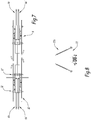
- Figure 1 shows a top view of a section insulator 1 according to the present invention while figure 2 shows a lateral view of the section insulator of figure 1 .
- the section insulator 1 comprises an insulating element 2, preferably of rectangular shape, and two connecting plates 4 (one on each end of the insulating element 2) for connecting the insulating element 2 to respective contact wires 6a, 6b of an overhead contact line through respective main clamps 16.
- Two respective short slideways 8 and long slideways 10 are arranged to be connected with the connecting plates 4 through spacers 12 for realizing a tract of overlap which ensures electrical continuity to the passage of the pantograph, thus avoiding trigger.
- the overhead contact line comprises, as known in the art, two adjacent insulated sections connected each other through the section insulator 1.
- the section insulator 1 further comprises, as above cited, two spacers 12 placed perpendicularly to a longitudinal axis X of the section insulator 1, said longitudinal axis X extending parallel to the contact wires 6a, 6b.
- the spacers 12 are fixed at one end to the respective slideway 8 and 10 and at the other end to the respective connecting plate 4 of the section insulator 1.
- Two pins 14 placed next to the respective spacer 12 and fixed to the connecting plate 4 are arranged to connect the respective main clamp 16 to the respective connecting plate 4 not rigidly, so that the main clamp 16 can absorb the vibrations of the contact wire 6a, 6b.
- each side of the section insulator 1 there are therefore the main clamp 16 and an auxiliary clamp 18, respectively arranged for being connected on one side to a respective contact wire 6a, 6b and on the other side to the connecting plate 4, so that the tensile force due to the contact wires 6a, 6b applies along the longitudinal axis X of the insulating element 2.
- a distance element 20 is placed next to the pins 14 and is a spacer between two plates that form each connecting plates 4.
- Two support arms 22 are respectively connected to the connecting plates 4 and are arranged for supporting, in a manner known per se, the section insulator 1 to the overhead contact line, through supporting members 22a.
- the section insulator 1 comprises the slideways 8 and 10 which are provided with horns 24 on one end.
- the four slideways 8, 10 with horns 24 create an overlap region 24' that guarantees that a pantograph moving on the contact wires 6a, 6b is always under tension, thus preventing electrical arcs which may damage the pantograph itself.
- the sidewall horns 24 extinguish any accidental discharge that may occur between the two isolated sections of the overhead contact, by bringing the electric discharge on the tips, so as to avoid that the discharge develops down the insulating element 2.
- Figure 3 shows a top view of a section insulator for two contact wires, wherein two respective couples of contact wires 6a, 6a' and 6b, 6b', are present on each side of the electric insulator 1.
- Figure 4 shows a transversal section of the section insulator of figures 1 and 3 wherein the support arms 22 are depicted.
- Figure 5 shows a top view of a section insulator 1' according to an alternative embodiment of the present invention
- figure 6 shows a lateral view of the section insulator of figure 5
- figure 7 shows a top view of an alternative embodiment of the section insulator of figure 5 including two couples of contact wires 6a, 6a' and 6b, 6b'.
- Figure 8 shows a transversal section of the section insulator 1' wherein the support arms 22 are depicted.
- the section insulator 1 of figures 1 to 4 is made of a rectangular insulating element 2 made of a fiberglass covered with silicone rubber.
- the rectangular shape allows a good mechanical resistance in all directions, and the short and long sideways 8, 10 are made of copper, which permits a good conductivity.
- the support structure of all the above components is made of stainless steel, so that the section insulator 1,1' has low maintenance costs due to the corrosion-resistant materials employed, and the simple geometric design permits to obtain a low weight and an easy installation.
- the overall good rigidity of assembly allows obtaining an high speed of travel for the pantograph.
- the section insulator 1' of figures 5 to 8 is made of a circular insulating element 2 made of fiberglass covered with PTFE (Polytetrafluoroethylene) and compressed at the ends with two terminals made of stainless steel.
- PTFE Polytetrafluoroethylene
- the section insulator 1, 1' is of a modular type and it allows easy replacement of damage parts and easy adaptation for two contact wires by keeping a suitable and high breaking load.
- there is only one insulating element 2 in the embodiment of figures 5 to 8 , there is only one insulating element 2 in case of only one contact wire 6a, 6b, and two insulating elements in case of two contacts wires for each side 6a, 6a' and 6b, 6b'.
- the section insulator 1, 1' of the present invention has the following advantages:
Landscapes
- Engineering & Computer Science (AREA)
- Mechanical Engineering (AREA)
- Current-Collector Devices For Electrically Propelled Vehicles (AREA)
Abstract
- an insulating element (2) placed between two contact wires (6a, 6b) of two adjacent sections of an overhead line;
- two clamps (16, 18) respectively connected on one side to a respective contact wire (6a, 6b) and on the other side to a connecting plate (4) arranged for being in turn connected to the insulating element (2), so that the tensile force due to the contact wires (6a, 6b) applies along the axis of the insulating bar;
- supporting means (22) directly connected to the insulating element (2) through the connecting plates (4) and arranged for supporting the section insulator (1, 1') to the overhead line.
Description
- The present invention relates to the field of supply of vehicles at electric traction.
- More specifically, the present invention relates to a section insulator for an overhead contact line intended for supplying electric traction vehicles.
- The section insulators are devices designed for sub-dividing an overhead contact line into individually electrical isolated sections accessible by pantographs.
- The purpose of section insulators is therefore to insulate two adjacent areas of an overhead contact line having a same voltage.
- Section insulators are known in the art, such as for example from document
EP 0064442 or documentFR 2537513 - There is therefore the need to have an innovative section insulator which is light, with a simple geometric design and cheap, thus overcoming the limitations of the prior art solutions.
- These and other objects are achieved by a section insulator for an overhead contact line having the characteristics defined in
claim 1. - Preferred embodiments of the invention are the subject matter of the dependent claims, whose content is to be understood as forming an integral part of the present description.
- Further characteristics and advantages of the present invention will become apparent from the following description, provided merely by way of non-limiting example, with reference to the enclosed drawings, in which:
-
Figure 1 shows a top view of a section insulator for one contact wire according to the present invention; -
Figure 2 shows a lateral view of the section insulator offigure 1 ; -
Figure 3 shows a top view of the section insulator for two contact wires; -
Figure 4 shows a transversal section of the section insulator offigures 1 and3 ; -
Figure 5 shows a top view of an alternative embodiment of the section insulator for one contact wire according to the present invention; -
Figure 6 shows a lateral view of the section insulator offigures 5 and7 -
Figure 7 shows a top view of an alternative embodiment of the section insulator for two contact wires; and -
Figure 8 shows a transversal section of the section insulator offigures 5 and7 . - Briefly, the section insulator of the present invention comprises a single insulating element linked with stainless steel plates to respective clamps (one clamp on each side of insulator); the clamp is connected on one side to contact wires of an overhead contact line, and on the other side to the stainless steel plates 4, so that the tensile force due to the contact wires applies along the axis of the insulating element. Supporting arms are directly connected to the stainless steel plates for supporting the section insulator to the overhead contact line.
-
Figure 1 shows a top view of asection insulator 1 according to the present invention whilefigure 2 shows a lateral view of the section insulator offigure 1 . - The
section insulator 1 comprises aninsulating element 2, preferably of rectangular shape, and two connecting plates 4 (one on each end of the insulating element 2) for connecting theinsulating element 2 torespective contact wires main clamps 16. Two respectiveshort slideways 8 andlong slideways 10 are arranged to be connected with the connecting plates 4 throughspacers 12 for realizing a tract of overlap which ensures electrical continuity to the passage of the pantograph, thus avoiding trigger. - The overhead contact line comprises, as known in the art, two adjacent insulated sections connected each other through the
section insulator 1. - The
section insulator 1 further comprises, as above cited, twospacers 12 placed perpendicularly to a longitudinal axis X of thesection insulator 1, said longitudinal axis X extending parallel to thecontact wires - The
spacers 12 are fixed at one end to therespective slideway section insulator 1. - Two
pins 14 placed next to therespective spacer 12 and fixed to the connecting plate 4 are arranged to connect the respectivemain clamp 16 to the respective connecting plate 4 not rigidly, so that themain clamp 16 can absorb the vibrations of thecontact wire - On each side of the
section insulator 1 there are therefore themain clamp 16 and anauxiliary clamp 18, respectively arranged for being connected on one side to arespective contact wire contact wires insulating element 2. - A
distance element 20 is placed next to thepins 14 and is a spacer between two plates that form each connecting plates 4. - Two support arms 22 (see
figure 4 ) are respectively connected to the connecting plates 4 and are arranged for supporting, in a manner known per se, thesection insulator 1 to the overhead contact line, through supportingmembers 22a. - As above indicated the
section insulator 1 comprises theslideways horns 24 on one end. The fourslideways horns 24 create an overlap region 24' that guarantees that a pantograph moving on thecontact wires - In the overlap region there is electrical continuity for the pantograph which moves from on section to the next adjacent one.
- The
sidewall horns 24 extinguish any accidental discharge that may occur between the two isolated sections of the overhead contact, by bringing the electric discharge on the tips, so as to avoid that the discharge develops down theinsulating element 2. -
Figure 3 shows a top view of a section insulator for two contact wires, wherein two respective couples ofcontact wires electric insulator 1. -
Figure 4 shows a transversal section of the section insulator offigures 1 and3 wherein thesupport arms 22 are depicted. -
Figure 5 shows a top view of a section insulator 1' according to an alternative embodiment of the present invention,figure 6 shows a lateral view of the section insulator offigure 5 andfigure 7 shows a top view of an alternative embodiment of the section insulator offigure 5 including two couples ofcontact wires - Elements similar to those of
figure 1 - figure 3 are indicated with the same reference numerals and infigures 5 to 7 only oneclamp 16 on each side of thesection insulator 1 is shown. In this alternative embodiment, there is a different way to connect thecontact wires insulating element 2. -
Figure 8 shows a transversal section of the section insulator 1' wherein thesupport arms 22 are depicted. - The
section insulator 1 offigures 1 to 4 is made of a rectangularinsulating element 2 made of a fiberglass covered with silicone rubber. - Thanks to fiberglass material it is possible reach a very high breaking load, and the silicone covering permits a long life even in the worst environmental conditions.
- The rectangular shape allows a good mechanical resistance in all directions, and the short and long sideways 8, 10 are made of copper, which permits a good conductivity.
- The support structure of all the above components is made of stainless steel, so that the
section insulator 1,1' has low maintenance costs due to the corrosion-resistant materials employed, and the simple geometric design permits to obtain a low weight and an easy installation. - The overall good rigidity of assembly allows obtaining an high speed of travel for the pantograph.
- The section insulator 1' of
figures 5 to 8 is made of a circularinsulating element 2 made of fiberglass covered with PTFE (Polytetrafluoroethylene) and compressed at the ends with two terminals made of stainless steel. - The
section insulator 1, 1' is of a modular type and it allows easy replacement of damage parts and easy adaptation for two contact wires by keeping a suitable and high breaking load. In the embodiment offigures 1 to 4 , there is only oneinsulating element 2, in the embodiment offigures 5 to 8 , there is only oneinsulating element 2 in case of only onecontact wire side section insulator 1, 1' of the present invention has the following advantages: - it allows an easier mounting procedure because the central body can be fixed on the overhead line without the slideways and after that, the slideways can be mounted and adjusted exactly;
- the rectangular shape of the
insulating element 2 allows a better mechanical resistance in the vertical direction; - there is the possibility to use a double round insulator in case of hard tensile force (section insulator 1')
- the direct connection of the
support arms 22 to theinsulating element 2, through the connecting plates 4, permits to support thesection insulator 1, 1' to the catenary system of the overhead line with different prior art techniques. - Clearly, the principle of the invention remaining the same, the embodiments and the details of production can be varied considerably from what has been described and illustrated purely by way of non-limiting example, without departing from the scope of protection of the present invention as defined by the attached claims.
Claims (6)
- Section insulator (1, 1') for an overhead contact line arranged for being placed between two isolated sections of said overhead contact line, said section insulator (1, 1') comprising :- an insulating element (2) placed between two contact wires (6a, 6b) of two adjacent sections of an overhead line;- two clamps (16, 18) respectively connected on one side to a respective contact wire (6a, 6b) and on the other side to a connecting plate (4) arranged for being in turn connected to the insulating element (2), so that the tensile force due to the contact wires (6a, 6b) applies along the axis of the insulating bar;- supporting means (22) directly connected to the insulating element (2) through the connecting plates (4) and arranged for supporting the section insulator (1, 1') to the overhead line.
- The section insulator (1, 1') according to claim 1, wherein the supporting means (22) further comprise supporting members (22a) for connection to the overhead line.
- The section insulator (1) according to claim 1 or 2, wherein the insulating element (2) is made of fiberglass covered with silicone rubber.
- The section insulator (1') according to claim 1 or 2, wherein the insulating element (2) is made of fiberglass covered with PTFE.
- The section insulator (1, 1') according to any of the preceding claims, further comprising two respective short slideways (8) and two long slideways (10) arranged to realize a tract of overlap which ensures electrical continuity to the passage of a pantograph on said overhead contact line.
- The section insulator (1, 1') of any of the preceding claims, further comprising horns (24) on one end of the respective short slideways (8) and long slideways (10), said horns (24) being arranged to extinguish accidental discharges occurring between the two isolated sections of the overhead contact line, so as to avoid that the discharge develops down the insulating element (2).
Priority Applications (5)
| Application Number | Priority Date | Filing Date | Title |
|---|---|---|---|
| EP17306497.3A EP3476649B1 (en) | 2017-10-31 | 2017-10-31 | Section insulator for an overhead contact line |
| DK17306497.3T DK3476649T3 (en) | 2017-10-31 | 2017-10-31 | SECTION INSULATOR FOR A TRAVEL LINE |
| ES17306497T ES2807956T3 (en) | 2017-10-31 | 2017-10-31 | Section insulator for an overhead contact line |
| US16/173,741 US11021080B2 (en) | 2017-10-31 | 2018-10-29 | Section insulator for an overhead contact line |
| CA3022727A CA3022727A1 (en) | 2017-10-31 | 2018-10-30 | Section insulator for an overhead contact line |
Applications Claiming Priority (1)
| Application Number | Priority Date | Filing Date | Title |
|---|---|---|---|
| EP17306497.3A EP3476649B1 (en) | 2017-10-31 | 2017-10-31 | Section insulator for an overhead contact line |
Publications (2)
| Publication Number | Publication Date |
|---|---|
| EP3476649A1 true EP3476649A1 (en) | 2019-05-01 |
| EP3476649B1 EP3476649B1 (en) | 2020-05-06 |
Family
ID=60327242
Family Applications (1)
| Application Number | Title | Priority Date | Filing Date |
|---|---|---|---|
| EP17306497.3A Active EP3476649B1 (en) | 2017-10-31 | 2017-10-31 | Section insulator for an overhead contact line |
Country Status (5)
| Country | Link |
|---|---|
| US (1) | US11021080B2 (en) |
| EP (1) | EP3476649B1 (en) |
| CA (1) | CA3022727A1 (en) |
| DK (1) | DK3476649T3 (en) |
| ES (1) | ES2807956T3 (en) |
Families Citing this family (6)
| Publication number | Priority date | Publication date | Assignee | Title |
|---|---|---|---|---|
| PT3441257T (en) * | 2017-08-09 | 2020-06-18 | Kummler Matter Ag | Stretch separation device and use of same |
| DK3476649T3 (en) * | 2017-10-31 | 2020-07-20 | Alstom Transp Tech | SECTION INSULATOR FOR A TRAVEL LINE |
| RU2743240C1 (en) * | 2019-11-29 | 2021-02-16 | Сергей Михайлович Асташин | Transitional sectional isolator of electrified railway contact network |
| CN111497688A (en) * | 2020-04-26 | 2020-08-07 | 广州地铁设计研究院股份有限公司 | A segmented insulator and high-speed overhead rigid catenary |
| CN111439168A (en) * | 2020-05-09 | 2020-07-24 | 中铁十二局集团电气化工程有限公司 | Installation and construction method of flexible contact net sectional insulator |
| CN121084256B (en) * | 2025-11-03 | 2026-03-20 | 阳谷江北电缆有限公司 | A connector for a segmented insulator and an overhead contact line. |
Citations (3)
| Publication number | Priority date | Publication date | Assignee | Title |
|---|---|---|---|---|
| GB1315839A (en) * | 1970-11-04 | 1973-05-02 | British Insulated Callenders | Section insulator for use in overhead conductors of electric traction systems |
| EP0064442A1 (en) | 1981-04-27 | 1982-11-10 | JACQUES GALLAND S.A., Société dite: | Section insulator for an electric traction overhead railway line, and process and apparatus for its application |
| FR2537513A1 (en) | 1982-12-08 | 1984-06-15 | Delachaux C | Section insulator for overhead electricity lines intended for supplying electric traction vehicles |
Family Cites Families (8)
| Publication number | Priority date | Publication date | Assignee | Title |
|---|---|---|---|---|
| US1773192A (en) * | 1928-10-15 | 1930-08-19 | Ohio Brass Co | Section insulator |
| US4250982A (en) * | 1979-08-27 | 1981-02-17 | Harvey Hubbell, Incorporated | Section insulator for catenary systems |
| US4424889A (en) * | 1981-03-12 | 1984-01-10 | Hoeckele Max | Phase break-section insulator devices of high tensile strength |
| US6206156B1 (en) * | 1997-07-18 | 2001-03-27 | Furrer & Frey Ag | Section insulator for conductor rails |
| ES2246743B2 (en) * | 2005-10-06 | 2007-08-16 | Metro De Madrid, S.A. | SECTION INSULATOR FOR RIGID CATENARY. |
| DE102010051379B4 (en) * | 2010-11-16 | 2013-02-07 | Furrer + Frey Ag | Section insulator |
| EP2805847B1 (en) * | 2013-05-22 | 2015-07-08 | Furrer + Frey AG | Device with two rigid conductor rails and a section isolator |
| DK3476649T3 (en) * | 2017-10-31 | 2020-07-20 | Alstom Transp Tech | SECTION INSULATOR FOR A TRAVEL LINE |
-
2017
- 2017-10-31 DK DK17306497.3T patent/DK3476649T3/en active
- 2017-10-31 ES ES17306497T patent/ES2807956T3/en active Active
- 2017-10-31 EP EP17306497.3A patent/EP3476649B1/en active Active
-
2018
- 2018-10-29 US US16/173,741 patent/US11021080B2/en active Active
- 2018-10-30 CA CA3022727A patent/CA3022727A1/en active Pending
Patent Citations (3)
| Publication number | Priority date | Publication date | Assignee | Title |
|---|---|---|---|---|
| GB1315839A (en) * | 1970-11-04 | 1973-05-02 | British Insulated Callenders | Section insulator for use in overhead conductors of electric traction systems |
| EP0064442A1 (en) | 1981-04-27 | 1982-11-10 | JACQUES GALLAND S.A., Société dite: | Section insulator for an electric traction overhead railway line, and process and apparatus for its application |
| FR2537513A1 (en) | 1982-12-08 | 1984-06-15 | Delachaux C | Section insulator for overhead electricity lines intended for supplying electric traction vehicles |
Non-Patent Citations (1)
| Title |
|---|
| GANSHORN R-D ET AL: "LIGHT-WEIGHT SECTION INSULATOR FOR OVERHEAD CONTACT LINES//LEICHTBAU-STRECKENTRENNER FUER OBERLEITUNGEN//ISOLATEUR DE SECTION LEGER POUR CATENAIRE", EB- ELEKTRISCHE BAHNEN, DIV-DEUTSCHER INDUSTRIEVERLAG, vol. 103, no. 7, 1 July 2005 (2005-07-01), pages 338 - 345, XP001232744, ISSN: 0013-5437 * |
Also Published As
| Publication number | Publication date |
|---|---|
| EP3476649B1 (en) | 2020-05-06 |
| US11021080B2 (en) | 2021-06-01 |
| DK3476649T3 (en) | 2020-07-20 |
| ES2807956T3 (en) | 2021-02-24 |
| US20190126776A1 (en) | 2019-05-02 |
| CA3022727A1 (en) | 2019-04-30 |
Similar Documents
| Publication | Publication Date | Title |
|---|---|---|
| US11021080B2 (en) | Section insulator for an overhead contact line | |
| AU2014270597B2 (en) | Device with two rigid busbars and a section insulator | |
| US9225075B2 (en) | High voltage device system of railcar and railcar | |
| KR20120027387A (en) | Cantilever for supporting live cables of railway, trolley and subway lines | |
| KR101746285B1 (en) | support clamp for conductor rail | |
| KR102036123B1 (en) | An antenna holder of mobile communication base station for high-speed railroad electric pole | |
| KR20140110324A (en) | support clamp and rigid bar support system including the same | |
| CN204488531U (en) | Exchange 25kV rigid section insulator | |
| US8618414B2 (en) | Holding device for an overhead line and overhead line configuration | |
| KR20170043437A (en) | Expansion joint | |
| US4250982A (en) | Section insulator for catenary systems | |
| KR101900512B1 (en) | rigid bar support system | |
| US4187934A (en) | Section insulator for catenary systems | |
| KR101415134B1 (en) | Section insulator for dc same phase | |
| CN203293937U (en) | Direct-current 3kV overall self-cleaning type rigidity section insulator | |
| KR20120004286U (en) | a clamp with earthing and electric supply warning | |
| US4029182A (en) | Overhead electric traction systems | |
| CN203293936U (en) | Direct-current 3kV overall self-cleaning type single line flexible section insulator | |
| CN205724785U (en) | Insulating support and electrical-wire support structure | |
| GB2521602A (en) | Overhead electrification line cantilever assembly | |
| EP3699022B1 (en) | Dampening support for a rigid catenary element of a rigid catenary system of a railway line | |
| CN201234090Y (en) | Horizontal double split conductive wire hanging hook | |
| RU2008115790A (en) | HIGH VOLTAGE ELECTRIC TRANSMISSION LINE AND HIGH VOLTAGE INSULATOR FOR THIS LINE | |
| KR20170039432A (en) | rigid bar | |
| RU2842741C1 (en) | High-voltage rod polymer insulators protection device against damage by partial surface discharges during contaminated surface moistening |
Legal Events
| Date | Code | Title | Description |
|---|---|---|---|
| PUAI | Public reference made under article 153(3) epc to a published international application that has entered the european phase |
Free format text: ORIGINAL CODE: 0009012 |
|
| STAA | Information on the status of an ep patent application or granted ep patent |
Free format text: STATUS: THE APPLICATION HAS BEEN PUBLISHED |
|
| AK | Designated contracting states |
Kind code of ref document: A1 Designated state(s): AL AT BE BG CH CY CZ DE DK EE ES FI FR GB GR HR HU IE IS IT LI LT LU LV MC MK MT NL NO PL PT RO RS SE SI SK SM TR |
|
| AX | Request for extension of the european patent |
Extension state: BA ME |
|
| STAA | Information on the status of an ep patent application or granted ep patent |
Free format text: STATUS: REQUEST FOR EXAMINATION WAS MADE |
|
| 17P | Request for examination filed |
Effective date: 20190424 |
|
| RBV | Designated contracting states (corrected) |
Designated state(s): AL AT BE BG CH CY CZ DE DK EE ES FI FR GB GR HR HU IE IS IT LI LT LU LV MC MK MT NL NO PL PT RO RS SE SI SK SM TR |
|
| GRAP | Despatch of communication of intention to grant a patent |
Free format text: ORIGINAL CODE: EPIDOSNIGR1 |
|
| STAA | Information on the status of an ep patent application or granted ep patent |
Free format text: STATUS: GRANT OF PATENT IS INTENDED |
|
| INTG | Intention to grant announced |
Effective date: 20200107 |
|
| GRAS | Grant fee paid |
Free format text: ORIGINAL CODE: EPIDOSNIGR3 |
|
| GRAA | (expected) grant |
Free format text: ORIGINAL CODE: 0009210 |
|
| STAA | Information on the status of an ep patent application or granted ep patent |
Free format text: STATUS: THE PATENT HAS BEEN GRANTED |
|
| AK | Designated contracting states |
Kind code of ref document: B1 Designated state(s): AL AT BE BG CH CY CZ DE DK EE ES FI FR GB GR HR HU IE IS IT LI LT LU LV MC MK MT NL NO PL PT RO RS SE SI SK SM TR |
|
| REG | Reference to a national code |
Ref country code: GB Ref legal event code: FG4D |
|
| REG | Reference to a national code |
Ref country code: CH Ref legal event code: EP Ref country code: AT Ref legal event code: REF Ref document number: 1266228 Country of ref document: AT Kind code of ref document: T Effective date: 20200515 |
|
| REG | Reference to a national code |
Ref country code: IE Ref legal event code: FG4D |
|
| REG | Reference to a national code |
Ref country code: DE Ref legal event code: R096 Ref document number: 602017016172 Country of ref document: DE |
|
| REG | Reference to a national code |
Ref country code: CH Ref legal event code: NV Representative=s name: NOVAGRAAF INTERNATIONAL SA, CH |
|
| REG | Reference to a national code |
Ref country code: DK Ref legal event code: T3 Effective date: 20200715 |
|
| REG | Reference to a national code |
Ref country code: SE Ref legal event code: TRGR |
|
| REG | Reference to a national code |
Ref country code: NO Ref legal event code: T2 Effective date: 20200506 |
|
| REG | Reference to a national code |
Ref country code: LT Ref legal event code: MG4D |
|
| REG | Reference to a national code |
Ref country code: NL Ref legal event code: MP Effective date: 20200506 |
|
| PG25 | Lapsed in a contracting state [announced via postgrant information from national office to epo] |
Ref country code: IS Free format text: LAPSE BECAUSE OF FAILURE TO SUBMIT A TRANSLATION OF THE DESCRIPTION OR TO PAY THE FEE WITHIN THE PRESCRIBED TIME-LIMIT Effective date: 20200906 Ref country code: GR Free format text: LAPSE BECAUSE OF FAILURE TO SUBMIT A TRANSLATION OF THE DESCRIPTION OR TO PAY THE FEE WITHIN THE PRESCRIBED TIME-LIMIT Effective date: 20200807 Ref country code: LT Free format text: LAPSE BECAUSE OF FAILURE TO SUBMIT A TRANSLATION OF THE DESCRIPTION OR TO PAY THE FEE WITHIN THE PRESCRIBED TIME-LIMIT Effective date: 20200506 Ref country code: FI Free format text: LAPSE BECAUSE OF FAILURE TO SUBMIT A TRANSLATION OF THE DESCRIPTION OR TO PAY THE FEE WITHIN THE PRESCRIBED TIME-LIMIT Effective date: 20200506 Ref country code: PT Free format text: LAPSE BECAUSE OF FAILURE TO SUBMIT A TRANSLATION OF THE DESCRIPTION OR TO PAY THE FEE WITHIN THE PRESCRIBED TIME-LIMIT Effective date: 20200907 |
|
| PG25 | Lapsed in a contracting state [announced via postgrant information from national office to epo] |
Ref country code: LV Free format text: LAPSE BECAUSE OF FAILURE TO SUBMIT A TRANSLATION OF THE DESCRIPTION OR TO PAY THE FEE WITHIN THE PRESCRIBED TIME-LIMIT Effective date: 20200506 Ref country code: HR Free format text: LAPSE BECAUSE OF FAILURE TO SUBMIT A TRANSLATION OF THE DESCRIPTION OR TO PAY THE FEE WITHIN THE PRESCRIBED TIME-LIMIT Effective date: 20200506 Ref country code: RS Free format text: LAPSE BECAUSE OF FAILURE TO SUBMIT A TRANSLATION OF THE DESCRIPTION OR TO PAY THE FEE WITHIN THE PRESCRIBED TIME-LIMIT Effective date: 20200506 Ref country code: BG Free format text: LAPSE BECAUSE OF FAILURE TO SUBMIT A TRANSLATION OF THE DESCRIPTION OR TO PAY THE FEE WITHIN THE PRESCRIBED TIME-LIMIT Effective date: 20200806 |
|
| REG | Reference to a national code |
Ref country code: AT Ref legal event code: MK05 Ref document number: 1266228 Country of ref document: AT Kind code of ref document: T Effective date: 20200506 |
|
| PG25 | Lapsed in a contracting state [announced via postgrant information from national office to epo] |
Ref country code: AL Free format text: LAPSE BECAUSE OF FAILURE TO SUBMIT A TRANSLATION OF THE DESCRIPTION OR TO PAY THE FEE WITHIN THE PRESCRIBED TIME-LIMIT Effective date: 20200506 Ref country code: NL Free format text: LAPSE BECAUSE OF FAILURE TO SUBMIT A TRANSLATION OF THE DESCRIPTION OR TO PAY THE FEE WITHIN THE PRESCRIBED TIME-LIMIT Effective date: 20200506 |
|
| PG25 | Lapsed in a contracting state [announced via postgrant information from national office to epo] |
Ref country code: SM Free format text: LAPSE BECAUSE OF FAILURE TO SUBMIT A TRANSLATION OF THE DESCRIPTION OR TO PAY THE FEE WITHIN THE PRESCRIBED TIME-LIMIT Effective date: 20200506 Ref country code: AT Free format text: LAPSE BECAUSE OF FAILURE TO SUBMIT A TRANSLATION OF THE DESCRIPTION OR TO PAY THE FEE WITHIN THE PRESCRIBED TIME-LIMIT Effective date: 20200506 Ref country code: CZ Free format text: LAPSE BECAUSE OF FAILURE TO SUBMIT A TRANSLATION OF THE DESCRIPTION OR TO PAY THE FEE WITHIN THE PRESCRIBED TIME-LIMIT Effective date: 20200506 Ref country code: RO Free format text: LAPSE BECAUSE OF FAILURE TO SUBMIT A TRANSLATION OF THE DESCRIPTION OR TO PAY THE FEE WITHIN THE PRESCRIBED TIME-LIMIT Effective date: 20200506 Ref country code: EE Free format text: LAPSE BECAUSE OF FAILURE TO SUBMIT A TRANSLATION OF THE DESCRIPTION OR TO PAY THE FEE WITHIN THE PRESCRIBED TIME-LIMIT Effective date: 20200506 |
|
| REG | Reference to a national code |
Ref country code: DE Ref legal event code: R097 Ref document number: 602017016172 Country of ref document: DE |
|
| REG | Reference to a national code |
Ref country code: ES Ref legal event code: FG2A Ref document number: 2807956 Country of ref document: ES Kind code of ref document: T3 Effective date: 20210224 |
|
| PG25 | Lapsed in a contracting state [announced via postgrant information from national office to epo] |
Ref country code: PL Free format text: LAPSE BECAUSE OF FAILURE TO SUBMIT A TRANSLATION OF THE DESCRIPTION OR TO PAY THE FEE WITHIN THE PRESCRIBED TIME-LIMIT Effective date: 20200506 Ref country code: SK Free format text: LAPSE BECAUSE OF FAILURE TO SUBMIT A TRANSLATION OF THE DESCRIPTION OR TO PAY THE FEE WITHIN THE PRESCRIBED TIME-LIMIT Effective date: 20200506 |
|
| PLBE | No opposition filed within time limit |
Free format text: ORIGINAL CODE: 0009261 |
|
| STAA | Information on the status of an ep patent application or granted ep patent |
Free format text: STATUS: NO OPPOSITION FILED WITHIN TIME LIMIT |
|
| 26N | No opposition filed |
Effective date: 20210209 |
|
| PG25 | Lapsed in a contracting state [announced via postgrant information from national office to epo] |
Ref country code: SI Free format text: LAPSE BECAUSE OF FAILURE TO SUBMIT A TRANSLATION OF THE DESCRIPTION OR TO PAY THE FEE WITHIN THE PRESCRIBED TIME-LIMIT Effective date: 20200506 |
|
| PG25 | Lapsed in a contracting state [announced via postgrant information from national office to epo] |
Ref country code: LU Free format text: LAPSE BECAUSE OF NON-PAYMENT OF DUE FEES Effective date: 20201031 Ref country code: MC Free format text: LAPSE BECAUSE OF FAILURE TO SUBMIT A TRANSLATION OF THE DESCRIPTION OR TO PAY THE FEE WITHIN THE PRESCRIBED TIME-LIMIT Effective date: 20200506 |
|
| PG25 | Lapsed in a contracting state [announced via postgrant information from national office to epo] |
Ref country code: IE Free format text: LAPSE BECAUSE OF NON-PAYMENT OF DUE FEES Effective date: 20201031 |
|
| PG25 | Lapsed in a contracting state [announced via postgrant information from national office to epo] |
Ref country code: TR Free format text: LAPSE BECAUSE OF FAILURE TO SUBMIT A TRANSLATION OF THE DESCRIPTION OR TO PAY THE FEE WITHIN THE PRESCRIBED TIME-LIMIT Effective date: 20200506 Ref country code: MT Free format text: LAPSE BECAUSE OF FAILURE TO SUBMIT A TRANSLATION OF THE DESCRIPTION OR TO PAY THE FEE WITHIN THE PRESCRIBED TIME-LIMIT Effective date: 20200506 Ref country code: CY Free format text: LAPSE BECAUSE OF FAILURE TO SUBMIT A TRANSLATION OF THE DESCRIPTION OR TO PAY THE FEE WITHIN THE PRESCRIBED TIME-LIMIT Effective date: 20200506 |
|
| PG25 | Lapsed in a contracting state [announced via postgrant information from national office to epo] |
Ref country code: MK Free format text: LAPSE BECAUSE OF FAILURE TO SUBMIT A TRANSLATION OF THE DESCRIPTION OR TO PAY THE FEE WITHIN THE PRESCRIBED TIME-LIMIT Effective date: 20200506 |
|
| P01 | Opt-out of the competence of the unified patent court (upc) registered |
Effective date: 20230823 |
|
| REG | Reference to a national code |
Ref country code: GB Ref legal event code: 732E Free format text: REGISTERED BETWEEN 20250213 AND 20250219 |
|
| REG | Reference to a national code |
Ref country code: ES Ref legal event code: PC2A Owner name: ALSTOM HOLDINGS Effective date: 20250310 |
|
| REG | Reference to a national code |
Ref country code: BE Ref legal event code: PD Owner name: ALSTOM HOLDINGS; FR Free format text: DETAILS ASSIGNMENT: CHANGE OF OWNER(S), ASSIGNMENT; FORMER OWNER NAME: ALSTOM TRANSPORT TECHNOLOGIES Effective date: 20241025 |
|
| REG | Reference to a national code |
Ref country code: CH Ref legal event code: U11 Free format text: ST27 STATUS EVENT CODE: U-0-0-U10-U11 (AS PROVIDED BY THE NATIONAL OFFICE) Effective date: 20251101 |
|
| PGFP | Annual fee paid to national office [announced via postgrant information from national office to epo] |
Ref country code: DE Payment date: 20251021 Year of fee payment: 9 |
|
| PGFP | Annual fee paid to national office [announced via postgrant information from national office to epo] |
Ref country code: GB Payment date: 20251022 Year of fee payment: 9 |
|
| PGFP | Annual fee paid to national office [announced via postgrant information from national office to epo] |
Ref country code: NO Payment date: 20251024 Year of fee payment: 9 |
|
| PGFP | Annual fee paid to national office [announced via postgrant information from national office to epo] |
Ref country code: DK Payment date: 20251027 Year of fee payment: 9 Ref country code: IT Payment date: 20251024 Year of fee payment: 9 |
|
| PGFP | Annual fee paid to national office [announced via postgrant information from national office to epo] |
Ref country code: FR Payment date: 20251030 Year of fee payment: 9 |
|
| PGFP | Annual fee paid to national office [announced via postgrant information from national office to epo] |
Ref country code: BE Payment date: 20251021 Year of fee payment: 9 |
|
| PGFP | Annual fee paid to national office [announced via postgrant information from national office to epo] |
Ref country code: SE Payment date: 20251021 Year of fee payment: 9 Ref country code: CH Payment date: 20251101 Year of fee payment: 9 |
|
| PGFP | Annual fee paid to national office [announced via postgrant information from national office to epo] |
Ref country code: ES Payment date: 20251216 Year of fee payment: 9 |